
Actuation Behavior of Hydraulically Amplified Self-Healing Electrostatic (HASEL) Actuator via Dimensional Analysis


1
Active Materials and Smart Living (AMSL) Laboratory, Department of Mechanical Engineering, University of Nevada, Las Vegas, NV 89154, USA
2
Advanced Materials and Processing Branch, NASA Langley Research Center, Hampton, VA 23666, USA
*
Author to whom correspondence should be addressed.
Actuators 2023, 12(5), 208; https://doi.org/10.3390/act12050208
Submission received: 25 March 2023
/
Revised: 11 May 2023
/
Accepted: 11 May 2023
/
Published: 18 May 2023
(This article belongs to the Special Issue Actuators in 2022)
Abstract
:Electroactive polymer (EAP) actuators are an example of a novel soft material device that can be used for several applications including artificial muscles and lenses. The field of EAPs can be broken down into a few fields; however, the field that will be discussed in this study is that of Soft Electrohydraulic (SEH or EH) actuators. The device that will specifically be studied is the Hydraulically Amplified Self-Healing Electrostatic (HASEL) actuator. The design of the HASEL actuator is simple. There are two compliant films that house a dielectric liquid, and with the application of a voltage potential, there is an output displacement and force. However, the actuation mechanism is more complex, thus there is a need to understand theoretically and experimentally how the actuator works. This study analytically describes the electrode closure and the experimental testing of the actuators. Then, dimensional analysis techniques are used to determine what factors are contributing to the function of the actuator. For this study, eight dimensionless Π groups were found based on the derived analytical equation. These Π groups were determined based on the input voltage, density, viscosity, and elastic modulus of the materials; these were chosen because of their major contribution to the experimental data. The Π groups that are of particular importance are related to the characteristic length, which is directly related to the displacement of the fluid, the fluid velocity, the fluid pressure, and the dielectric constant. From this study, relationships between the output force, the electrostatic contributions, and other parameters were determined. All in all, this type of analysis can provide guidance on the development of high-performance HASEL actuators.
1. Introduction
Dimensional analysis serves to help determine what parameters are important during the experimentation process [1]. Analytical models and equations provide some context and can provide an overall description of a physical system. However, models do not provide the necessary information to fully test and implement the physics of a system. When considering experimental testing and design, there are often a number of parameters and variables that can be altered or completely neglected. To determine this information experimentally can be difficult and time consuming. Therefore, dimensional analysis can serve as a powerful tool to bridge the gap between mathematical and physics modeling efforts and experimental studies. Dimensional analysis is a great tool for complex physics systems such as fluid dynamics and has just recently been applied to another complex physical system, EAPs [2,3]. The work conducted by Olsen et al. shows that dimensional analysis can be a powerful tool for multiphysics systems [2,3].
Another emerging complex multiphysics system of note, where dimensional analysis can serve as a powerful analysis tool, is the electrohydraulic (EH) actuator. These actuator systems utilize a complex electro-mechanical-hydraulic activation mechanism to cause actuation. There are many different EH devices; however, for this study, the Hydraulically Amplified Self-Healing Electrostatic (HASEL) actuator will be studied. This actuator was originally developed by the Keplinger Group of the Intelligent System/Max Planck Institute; the mechanism uses hydraulic amplification and the electrostatic “zipping” (gradual closure) of the electrodes to cause an output force and displacement [4,5,6,7]. The HASEL actuator is an alternative to solid dielectric elastomer actuators (DEAs). This novel actuator has excellent capabilities to be used as artificial muscles and other robotic manipulators [8,9]. The hydraulic amplification of the HASEL leads to larger outputs while maintaining its lightweight and flexibility [5]. Additionally, the use of a liquid dielectric medium helps prevent dielectric breakdown in the actuator, as seen with solid DEAs. However, more information is needed to appropriately use these devices in a meaningful and effective way. Before further explaining the path of study, it is beneficial to provide the background of the HASEL actuator.
The underlying structure of the HASEL actuator is straightforward, in that it comprises three materials: (i) a liquid dielectric, (ii) a compliant polymer film, and (iii) a flexible electrode. First, the polymer film is formed into a shell of a given geometry, and this can be a circular, rectangular, etc. [4,5,6,7]. Then, a given volume of liquid dielectric material is then injected into the shell. Finally, flexible electrodes are attached to specific locations on the polymer shell (Figure 1). In general, these electrodes are placed strategically such that the actuator will experience hydraulic amplification where needed. The actuation mechanism is based on current actuator technologies, electrostatic actuation of small systems and hydraulic actuation of pistons and other traditional robotic components. These two actuation mechanisms are interesting in that they work sequentially. The electrostatic actuation mechanism is triggered first with the application of an electric field. When an electric field is applied to the compliant electrode, the electrodes gradually collapse toward each other due to the electronic polarization of the dielectric film and the liquid dielectric [8,10,11]. Electronic polarization is caused by the dipole moment induced by the movement of the molecules’ electrons [8,10,11]. The gradual closure of the electrodes draws the films toward each other and forces the liquid dielectric in the inactive chamber(s) of the actuator. The hydraulic mechanism is simpler, in that the movement of the fluid into the inactive chamber causes an output displacement by proxy of the film shell. The majority of the liquid dielectric is pushed into the inactive chamber. Because of the film shell and the applied pressure from the electrostatic mechanism, pressure is created in the inactive section of the actuator and an output force is generated (Figure 2).
The HASEL actuator has a fairly straightforward fabrication method and a fairly simple actuation method, on the surface. However, the actuation mechanism is quite complex when considering physics-based modeling. As mentioned previously, there are three major components to modeling that must be considered: (i) the electrical, (ii) the fluid dynamics, and (iii) the mechanical. These different physics systems must be connected to accurately describe the entire system. Thus, more information is needed to appropriately use these devices in a meaningful and effective way. This study will consider the physics and the experimental data to gain further insight on how these actuators function. First, an analytical model will be introduced that describes the zipping of the electrodes. This zipping mechanism is directly related to the displacement of the fluid; thus, the analytical equation will provide a good basis for describing the actuator output. Other studies have considered the dynamics of the HASEL actuator system; however, various constraints and considerations are not included in those analyses [9,12]. Rothemund et al. considers the dynamics of EH actuators; however, Poiseuille Flow conditions are used as a simplification to define the boundary conditions of the actuator [9]. The model developed by Kellaris et al. neglects the contribution of the liquid dielectric and the mechanical properties of the film [12]. Furthermore, the current literature has not considered using dimensional analysis as a method of relating the experimental output to the analytical models. Equipollent work has considered the introduction of dimensionless quantities into their analysis; however, the formal use of Π groups to relate the various parameters of the system to each other has not been considered [5,9,12]. Lastly, the current research is lacking detail regarding how the materials affect the actuator system as a whole. Some of the research considers different dielectric materials, but no formal in-depth study has focused on these materials individually and their collective behavior in the actuation system [13,14,15,16]. Thus, there is an overall disconnection between the theory and the experimentation, that can be connected via dimensional analysis.
Considering the current state of the literature, this study aims to further the field of EH actuators and the Peano-HASEL actuator by way of a few objectives. The first objective is to introduce an analytical model for the zipping mechanism of the actuator; this model will act as a basis for the dimensional analysis. The second objective is to apply the Buckingham Pi theorem to the analytical equation to effectively compare and relate the experimental results to the analytical equation. The final objective is to consider in situ experimental results and how each variable parameter affects the system. By considering this path of study, the understanding of HASEL actuators and EH actuators will be fostered theoretically and experimentally. By analyzing these actuators using mathematical analysis and experimental work, HASEL actuators can be used in robotic systems more effectively and open the door to further applications not currently explored.
2. The Analytical Equation
2.1. Derivation of the Electrostatics
For this system, the electrostatics act as an applied force along the length of the electrode. The coupling of the electrical to the mechanics will be discussed further in Section 2.4. However, the general derivation begins with the parallel-plate capacitor system with mixed dielectric mediums. The derivation begins with the definition for capacitance:
The definition for the voltage potential across the film material and the liquid dielectric
is substituted into Equation (2), resulting in:
From this point, the electrostatic potential energy is defined using
is defined by inserting Equation (4) into Equation (5). The electrostatic force in the y direction is determined by taking the derivative across the thicknesses of the dielectric mediums:
The full derivation is provided in Appendix A.1.
2.2. Derivation of the Fluid Mechanics
The fluid mechanics of the system is derived based on the assumption that the fluid is acting under a hinged plate (Figure 3) [17]. The plate is oriented at angle θ, and θ is considered only a function of time. The fluid itself is considered to be a Newtonian fluid under laminar flow conditions with a given viscosity. No slip conditions are assumed for the walls of the system. Additionally, for the case of the Peano-HASEL actuator, the geometry is such that the small angle approximation can be used. To begin the derivation, the average velocity of the fluid in the x direction is determined using the conservation of mass:
Next, the force of the fluid under the plate must be considered. The standard momentum equations are used [1]:
Then, Equations (10) and (11) is reduced to
The full derivation is provided in Appendix A.2.
2.3. Derivation of the Solid Mechanics
The solid mechanics section sets up the motion of the film material; however, because the film material is highly compliant, the typical rigid body dynamics does not apply here. In an effort to capture the compliant nature of the electrode and film material, the section is modeled as a beam in bending that undergoes large deformations [18]. The end boundary conditions are designated as fixed-roller (as the model only looks at the activated section) (Figure 4). The material itself is modeled as a linear-elastic orthotropic material with properties oriented in 0° and 90° [19]:
Now, the Lagrange technique for determining the equations of motion is applied here. First, the kinetic energy (T) and the potential energy (V) are defined by
Then, integration of the equations is conducted such that the result is
(the full derivation is provided in Appendix A.3) [18].Using this derivation, the system can be described only in the w direction. Equation (18) is further simplified by virtue of the fact that the system is non-holonomic.
2.4. The Electro-Mechanical-Hydraulic Equation
Now that the three major physics contributors have been laid out, the analytical equation can be assembled. First, the electrostatic force is added to the equation as the applied force in the system. The dynamics of the solid film material directly changes the thickness of the liquid dielectric; therefore, the electrical mechanism must be coupled to the solid mechanics mechanism. This is performed by relating the deflection , to the thickness of the liquid dielectric:
The liquid dielectric is now defined as a function of the maximum thickness, the film thickness, and the slope of the beam as it is deflecting. The resulting applied force is
Next, a solid–fluid mechanism must be determined. Looking at Figure 4 and Equation (10) a connection can be made between angle of the plate as described and the deflection of the beam. In beam theory, the slope of the beam is defined as the angle of the beam deflection. This variable is directly connected to the angle of the rigid plate using
This can then be represented in the fluid dynamics equations by substituting Equation (21) into Equations (12) and (13), resulting in
In terms of the actuation system as a whole, the fluid dynamics acts as a dissipation force as the electrodes are collapsing toward each other [9,20]. As mentioned in Section 2.3, the Lagrange technique for determining the equation of motion is used in this analysis. However, the equation is slightly altered to include the applied force and the dissipation force:
This equation has an x and a y component; however, as mentioned previously, the beam in bending can be represented purely in the y direction. As a means to simplify the complex system, only the y direction will be considered (Figure 5):
3. The Dimensional Analysis
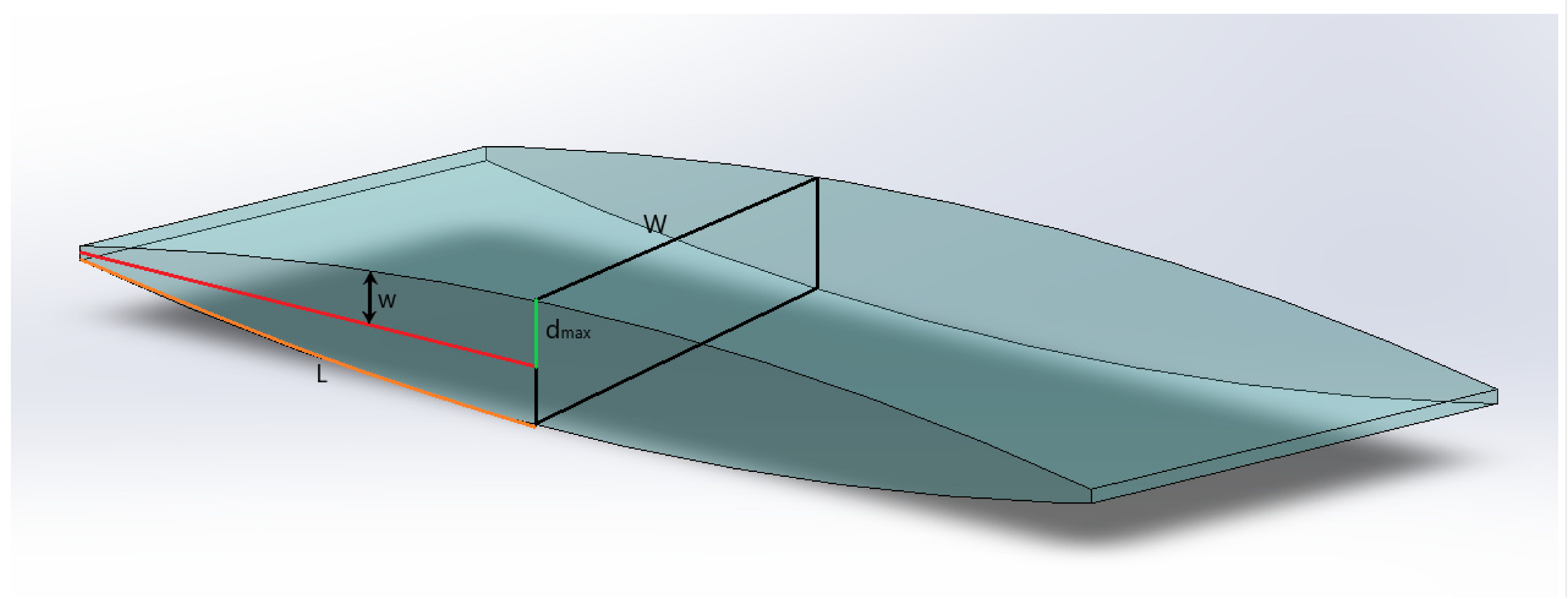
Considering the analytical theory developed in Section 2, the dimensional analysis can now be conducted. Although the proposed equation of motion is quite complex, the Buckingham Pi method of dimensional analysis will be used [1,2,21,22]. To begin the analysis, we consider all the dimensional parameters involved in the equation. Figure 6 serves as an approximation for the actual actuator system; this system is the three-dimensional version of the analytical setup described in Section 2. Based on the analytical equation and Figure 6, it is assumed that the actuator system takes the shape of a rectangular duct. Again, this neglects three-dimensional edge effects. By defining the set as such, a characteristic length can be defined to represent several of the parameters based on the geometry alone. The characteristic length for a rectangular is defined as
The analytical equation is designed to describe the motion of the electrode deflection ; therefore, as the electrodes zip closed, the actuator has a half thickness of (as seen in Figure 6). So, the characteristic length will be defined as
Now that a characteristic length has been defined for the system, the rest of the dimensional parameters can be listed. Table 1 describes all of the dimensional parameters of note in the analytical equation. Additionally, the fundamental dimensions are defined in Table 1 as well. For this actuator system four fundamental dimensions will be used, mass (M), length (L), time (T), and current (i). The dimensional parameters are also separated by declaring their dependence in the actuation system (Table 1). For example, the characteristic length is defined as a dependent variable because the deflection of the electrode is based on all of the other dimensional parameters. Based on this initial setup it can be seen that eight Π groups will be obtained. From this point, four dimensional parameters are chosen to be the repeating parameters in the solution. In general, the repeating parameters should be independent and contain all of the primary dimensions [1,2,21,22]. The repeating parameters should not primarily consist of powers of the fundamental dimensions [1,3,21,22].
The four repeating parameters chosen are, Young’s modulus (Y), the fluid density (ρ), the fluid viscosity (μ), and the applied voltage (V). As an additional selection criterion specific to this study, the repeating parameters must be parameters that can be easily tested or verified via experimentation. The applied voltage was chosen because it is a direct experimental parameter. It can be varied based on how the experiment is conducted. The viscosity was chosen because it is an experimental parameter that was measured in the laboratory experimentally. Similar to the voltage, this value can be varied based on a parametric study of the liquid dielectric material. The elastic modulus was chosen because it is an experimental parameter that was measured in the laboratory experimentally, as well. Similar to the voltage and dynamic viscosity, this value can be varied based on a parametric study of the film materials. The density was chosen as an additional parameter because it is independent in the system, it can be measured experimentally if needed and it can be varied based on a parametric study of the liquid dielectric materials. All in all, the repeating parameters that were chosen can be changed experimentally and each parameter can act as a control point in the test. In terms of the parameter dependence, all of the selected parameters are independent as well. As mentioned previously, the voltage is the input control for the zipping motion. The elastic modulus is a material property that remains constant and is independent from the rest of the system. The dynamic viscosity and the density of the fluid are also constant properties of the material and are independent of the actual zipping mechanism.
As a side note, the dielectric constant has a * next to it. This is due to its status as an independent and dependent variable. Examining the applied force in Equation (20), it can be seen that this term is dependent because it contains a deflection term. This deflection term is closely tied to the dielectric constant terms for the liquid dielectric and the polymer film. If the rest of the terms are taken out and the focus is on the dielectric constant terms and the thicknesses, the following expression is obtained.
From this expression, a new variable called the permittivity () can be obtained. This is the value dimensional parameter listed in Table 1. This parameter has the dimensions of due to the additional length term from the thickness of the film. This expression can further be reduced to the following expression.
This is the value dimensional parameter listed in Table 1. From the expression above the following relationship can be made, , where is a constant that is a function of position and time. Thus, the term is defined as
If acts as a general constant (as a means to observe ), then can act as an independent variable that can be experimentally tested. Now that the final setup is complete, the groups are found (Table 2). The groups were calculated using MATLAB. Each group resulted in a system of equations, and a script was created that solve the system. The full derivation is provided in Appendix A.4. The most important of these newly defined groups is which is called the Washington–Kim (WK) group. This dimensionless group will be discussed further in Section 5.
4. Experimental Testing
4.1. Testing the Material Properties
As mentioned previously, this study looks at the theoretical background of HASEL actuators and the experimental output as well. For the experimental work, an in-depth study was conducted that looked at four different dielectric film materials and four different liquid dielectric materials. A variety of materials are tested as a way to determine which component of the system has a greater effect on the overall actuation system. Additionally, the testing of a variety of materials also allows for comparison and the ability to determine the quality of materials needed to fabricate effective and robust EH actuators. For the experimental study, two film materials, biaxially oriented polypropylene (BOPP) and silicone rubber (Ecoflex 00-30 Platinum Cure) (EF), commonly used in the literature were tested along with two other commercially available film materials, low-density polyethylene (LDPE) and cast polypropylene (CPP) [5,6,7]. The mechanical and electrical properties of the films were tested. The liquid dielectric materials used were mineral oil (MO), olive oil (OO), grapeseed oil (GO), and silicone oil (SO), all of which are commercially available and (excluding SO) safe for human consumption. Mineral oil was chosen as an alternative to the liquid dielectric materials used in literature [5,6,7]. The other oils were chosen based on their biocompatibility, accessibility, and electrical properties.
For the film material mechanical properties, the stress–strain behavior was tested at laboratory temperature (20 °C). The films were tested using the DMA (Pyris Diamond Dynamic Mechanical Analyzer) at 1 Hz with an applied load and the load and strain were measured. The experimental tests captured the properties of the film in the machine direction (MD) and the transverse direction (TD). MD denotes the direction that the material was drawn in during the film fabrication process; TD is the direction perpendicular to the MD. The EF films were fabricated in the laboratory using a casting method, so the MD and the TD are the same. The capacitance of the film material was measured as well using a bench top LCR meter (ET4510 Digital Benchtop LCR Meter and Yamato DX400 Gravity Convection Oven) and dielectric constant was calculated using methods from literature [23]. The viscosity of the fluid was using a bench top viscometer (CGOLDENWALL NDJ-5S Rotary Viscometer). Additional material properties were tested; however, for the purposes of this study, we specifically want to consider the elastic modulus (Y), the dielectric constant (ε), the fluid viscosity (μ), and the fluid density, at laboratory temperature (20 °C). The fluid density was not tested due to the fact that a large amount of data exist for this particular property. All the variables listed are contributors in the analytical equation; therefore, the experimental results can relate back to the theoretical work via dimensional analysis.
4.2. Relevant Results from Testing the Material Properties
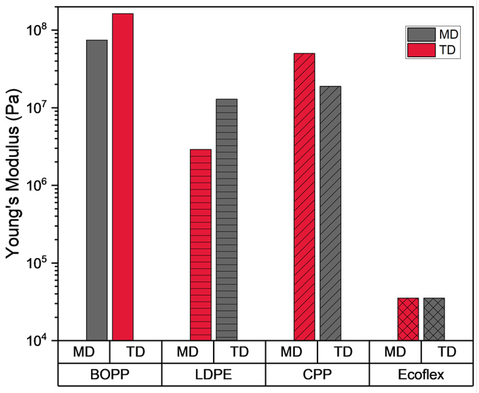
As mentioned in Section 2, for the analytical model, the polymer film material is considered to be a linear-elastic material, thus the elastic modulus is the property used to describe the material. Based on the results, it can be seen that BOPP, followed by CPP have the highest elastic modulus values (Figure 7). The results indicate that these are hard, brittle plastic materials that are fairly tough. The results also show significant differences between the MD and the TD, which tells us that the orientation of the polymer material matters during the fabrication process. In terms of actuator durability, a strong, tough polymer that can maintain a level of compliance is ideal. It is important to note that temperature does have a considerable affect; however, the current iteration of the analytical model does not consider temperature, so this property can be neglected for now.
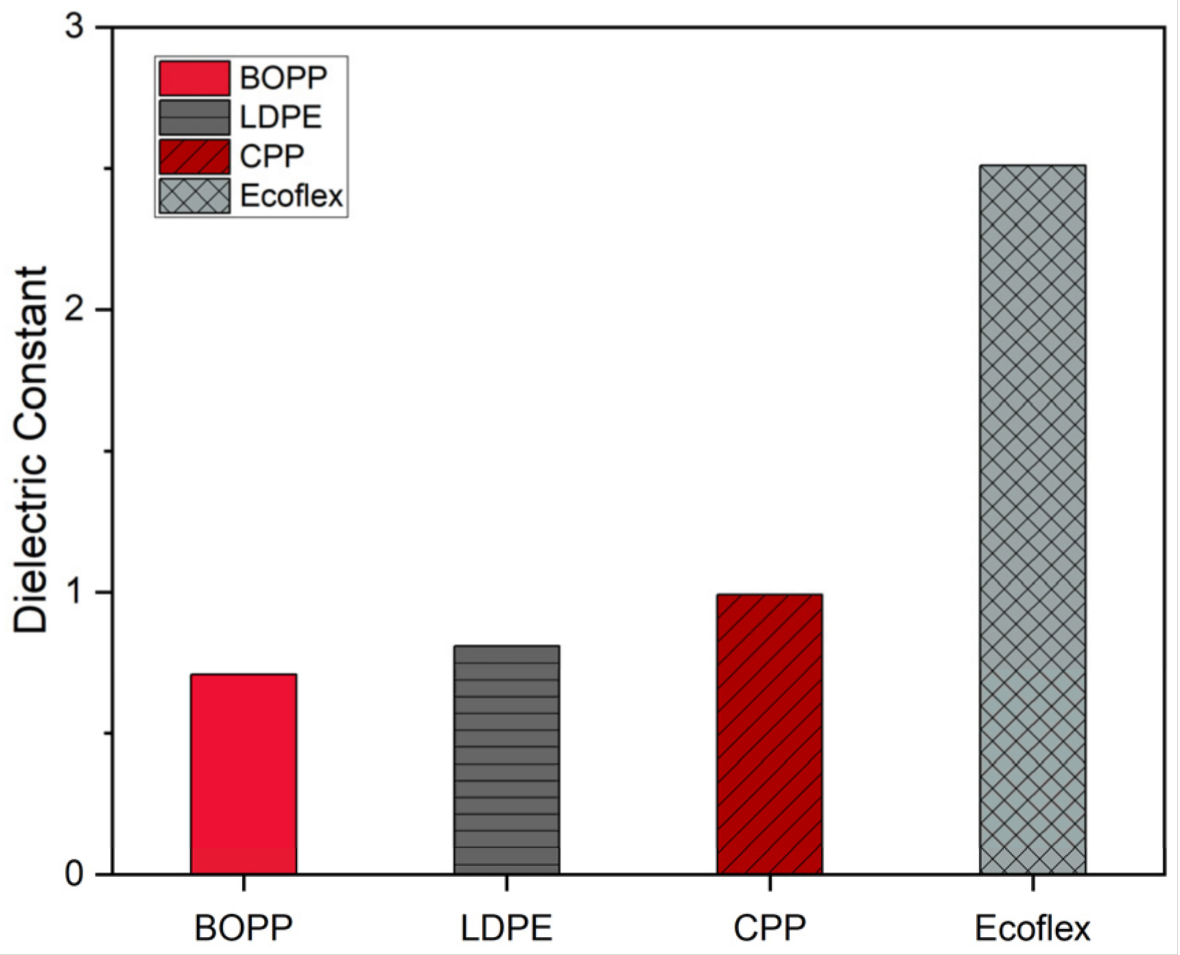
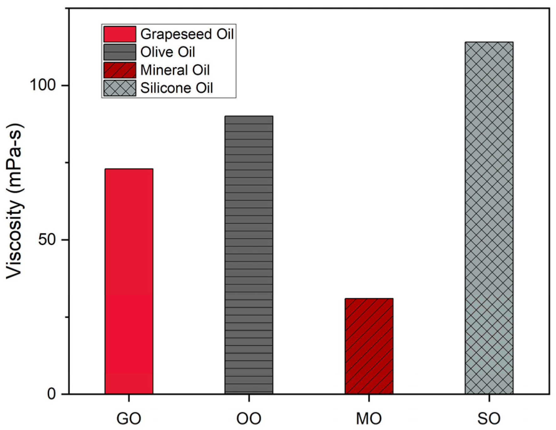
Looking at the dielectric constant tests of the film material, EF has the highest dielectric constant, followed by CPP (Figure 8). However, the dielectric constant values for the non-elastomeric film materials are within ±0.29 of each other. Overall, all the dielectric constant values are low, which means that the dielectric constant of the liquid dielectric material is the main contributing factor to the electrostatic mechanism. This is also supported by the fact that the dielectric constant values of the liquid dielectric materials are higher than the experimental results of the film dielectric constant [24]. Figure 9 shows the experimental data for the viscosity of the liquid dielectric material. It can be seen that silicone oil has the highest viscosity, followed by olive oil. It is also important to note that the viscosities of the plant-based oils are very similar. The differences can be attributed to the differences in fatty acid composition [25,26,27].
4.3. Relevant Results from Testing the Actuator Performance
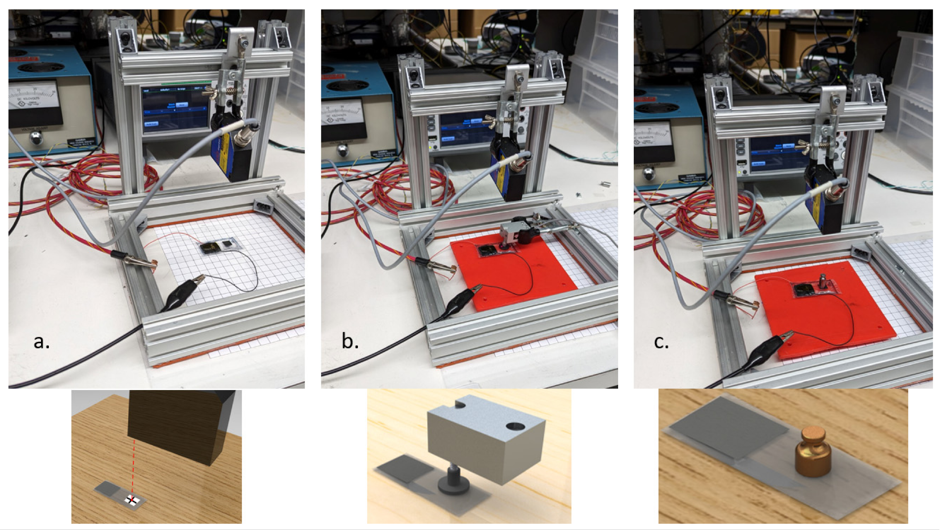
After the material properties were tested, the output displacement was tested using a laser displacement sensor and the vertical displacement (defined as the y direction) and the strain was measured as a function of the applied voltage (Figure 10 and Figure 11). The vertical force was measured using two different methods. The first set of output force data was taken using a load cell (Transducer Techniques GSO-100, Transducer Techniques, Temecula, USA) and measured as the voltage increased (Figure 10 and Figure 12). The voltage potential was applied using the Gamma High Voltage Research ES30 power supply. The second force measurement was a lifting force test; a 5 g mass was placed on the actuator and the displacement of the mass was taken with the maximum applied voltage (9 kV). Figure 13 provides the maximum displacement from lifting 5 g and the response time. Considering the reported results, there is a need to better correlate the theoretical analysis with the experimental data. There is also a need to correlate the experimental material properties to the experimental output performance. There is clearly a relationship between the electrical properties, mechanical properties, and hydraulic properties of the dielectric materials; however, the extent of the contribution is still a question.
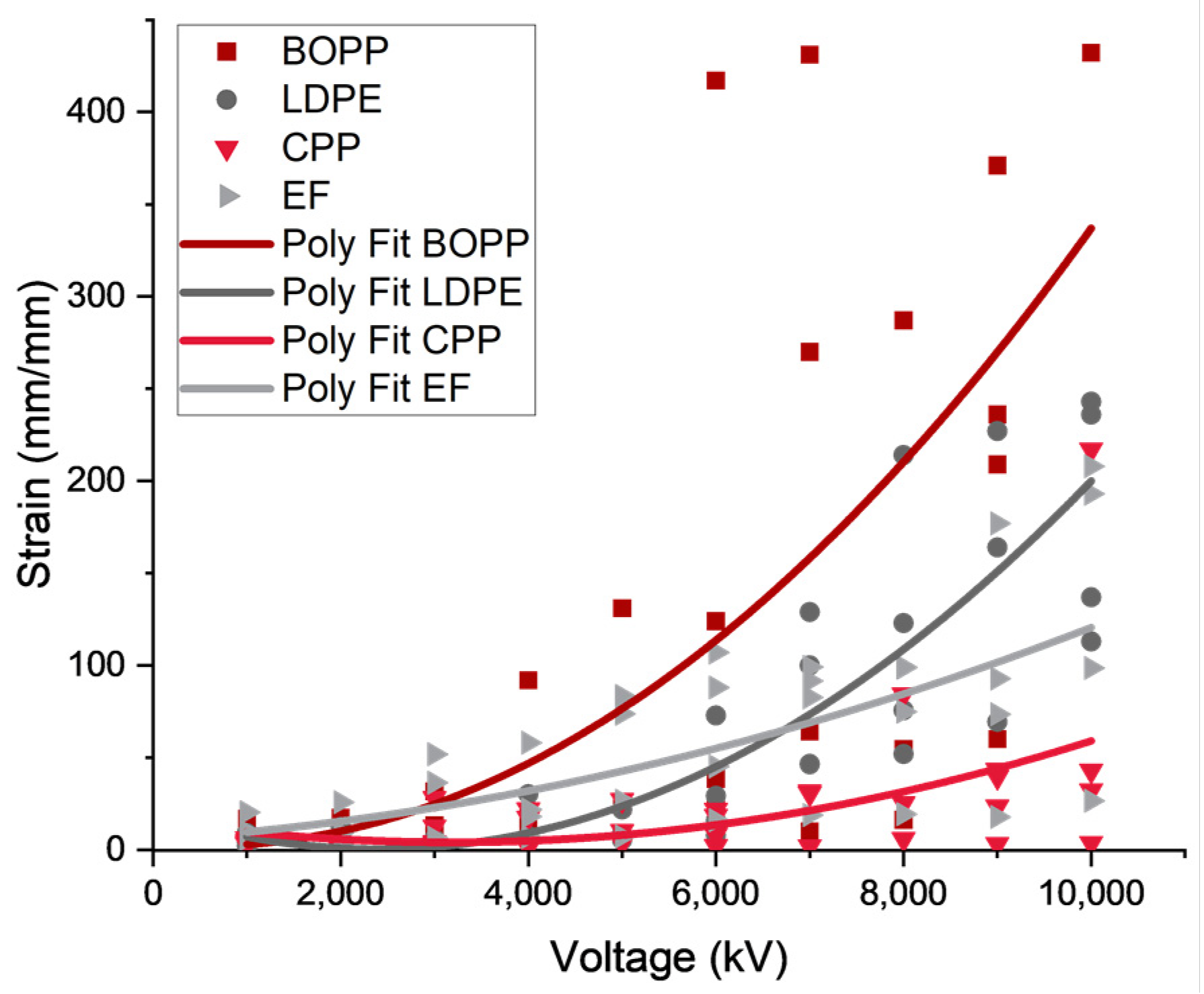
As seen in Figure 11, Figure 12 and Figure 13, it can be seen that the change in the film material causes substantial differences in the output performance. To better illustrate the voltage contribution, a second-order polynomial fit was applied to the data. From the analytical equation (Equation (7)), the applied electrostatic force has a direct relationship to the applied voltage of the system. This direct relationship is . From the data, the hard, brittle plastic BOPP performs the best in the load cell tests for most of the oils, followed by the LDPE. However, for the lifting tests, the BOPP performs poorly, and the LDPE performs well for the majority of the liquid dielectric specimens. Throughout the data, a weak correlation between the changes in the liquid dielectric and the output performance can be seen. This could be due to the fact that the viscosity values are similar between the liquid dielectric materials or that the mechanical deformation of the film dominates the system. Considering these questions, further discussion of dimensional analysis (Section 5) will help determine what may be contributing to the overall actuation mechanism.
5. Discussion
Table 2 provides the eight Π groups that were determined based on the analytical equation derived in Section 2 and the Buckingham Pi theorem of dimensional analysis (Section 3). From these results, there are five groups of immediate interest, these are Π1, Π2, Π3, Π6, and Π8. These five Π groups will be discussed in detail.
5.1. Π1 Group: Mass Flow Rate—Fluid Displacement, Viscous, and Viscoelastic Contributions
As mentioned in Section 2, the characteristic length is dependent on the deflection of the electrode and the width of the electrode. However, the parameter of note is the deflection, this represents the electrode closure and furthermore the displacement of the fluid in the film packet. Based upon the results of the Π group, only the properties of the fluid and the properties of the film material have an effect on the output of the actuators. More specifically, this describes the ratio of the mass flow rate of the fluid to the viscous forces of the fluid. Thus, describing the displacement of the liquid dielectric. Considering the experimental results, it can be seen that the displacement of the fluid is largely affected by the viscoelastic behavior of the film material. However, the variations seen between the fluid materials can be attributed to the density and viscosity of the fluids. In fact, based on this Π group relationship and the experimental data, when the density and the elastic modulus are both higher (i.e., in the case of olive oil and BOPP) the actuator displacement is higher, meaning that more fluid was displaced. The same result can be seen when the elastic modulus of the material is lower, and the density of the liquid dielectric is lower (i.e., in the case of EF and MO). However, this relationship does not account for all the experimental cases, such as the silicone oil samples. The Π group further displays that the viscosity of the fluid material is a major contribution. For example, looking at silicone oil, it has a higher viscosity and density of all the oils, but when it is contact with a low elastic modulus film, the overall displacement increases. This group describes the relationship between the solid and the fluid materials as it relates to the overall movement of the fluid.
5.2. Π2 Group: Fluid Velocity and Film Stiffness
The fluid velocity is a combined term that was determined in Section 2, but nonetheless is important to take note of. The fluid velocity not only describes the movement of the fluid but also the reaction time of the actuators. This is because the interaction of a compliant film material affects the speed of the fluid motion. The film material acts as the wall that the fluid is moving against, and is deforming due to the applied force, the pressure of the fluid, and the viscoelastic behavior of the film itself. The current experimental data cannot inform the direct relationship between these quantities as seen in Section 4. However, finite element modeling insights may be able help draw further conclusions about the relationship between the fluid velocity and the viscoelastic forces from the film material.
5.3. Π3 Group: Output Force—Fluid Pressure and Viscoelastic Contributions
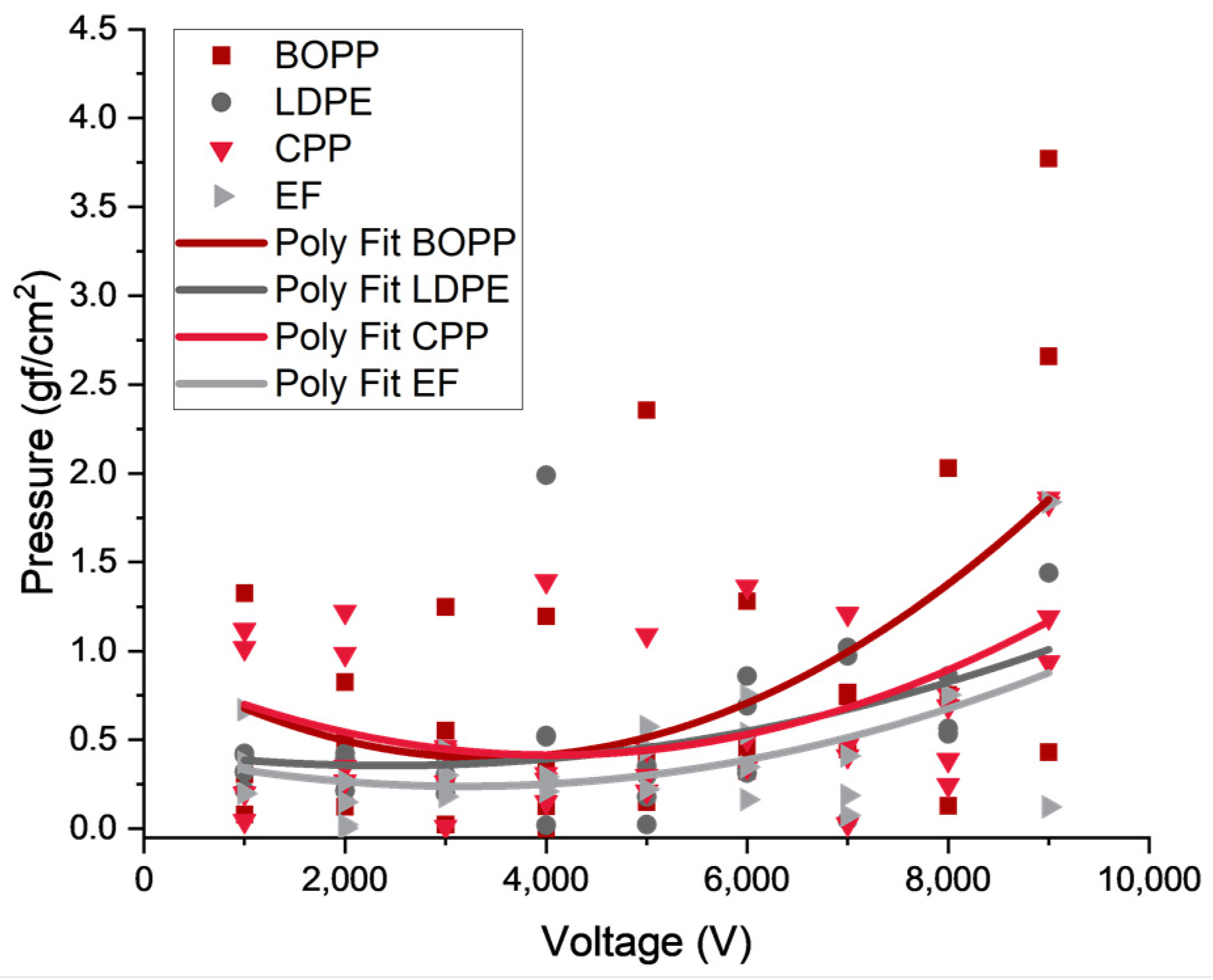
The relationship between the fluid pressure and dielectric materials is interesting because it no longer concerns the fluid properties. It is purely the ratio between the pressure and the stiffness. This Π group describes the output force of the actuator. The film material contributes to the output force due to its stiffness. The liquid dielectric can only deform the film so far; thus, a maximum internal pressure exists due to the stiffness of the film. The output force results from the experimental tests have a correlation between the film material but there is no clear correlation between the output force and the liquid dielectric. This is seen in both versions of the output force test (the load cell test and the lifting force test). This variation in the data is related to the internal pressure contributions. The internal pressure was not measured, so a strong correlation cannot be determined. However, a loose correlation can be made between the output force and the material stiffness. The output force for the load cell tests are higher with a stiffer film material. Thus, the other properties (viscosity and density) of the liquid dielectric do not strongly contribute to the output force.
5.4. Π6 Group [Washington–Kim Group]: The Electro-Mechanical-Hydraulic Relationship
Π6 describes the contribution of all the parameters to the actuation system. This is of particular importance from a theoretical standpoint because this group directly shows the contributions from the electrical, mechanical, and hydraulic relationship, thus this Π group is denoted as the Washington–Kim (WK) group. The analytical equation shows that there is some sort of multiphysics relationship, but the dimensional analysis clarifies the contributions of the independent and dependent parameters. However, the most important feature to note is that this Π group shows the contribution of the electrostatics and the electric field and how that relates to the viscous forces, stiffness, and density.
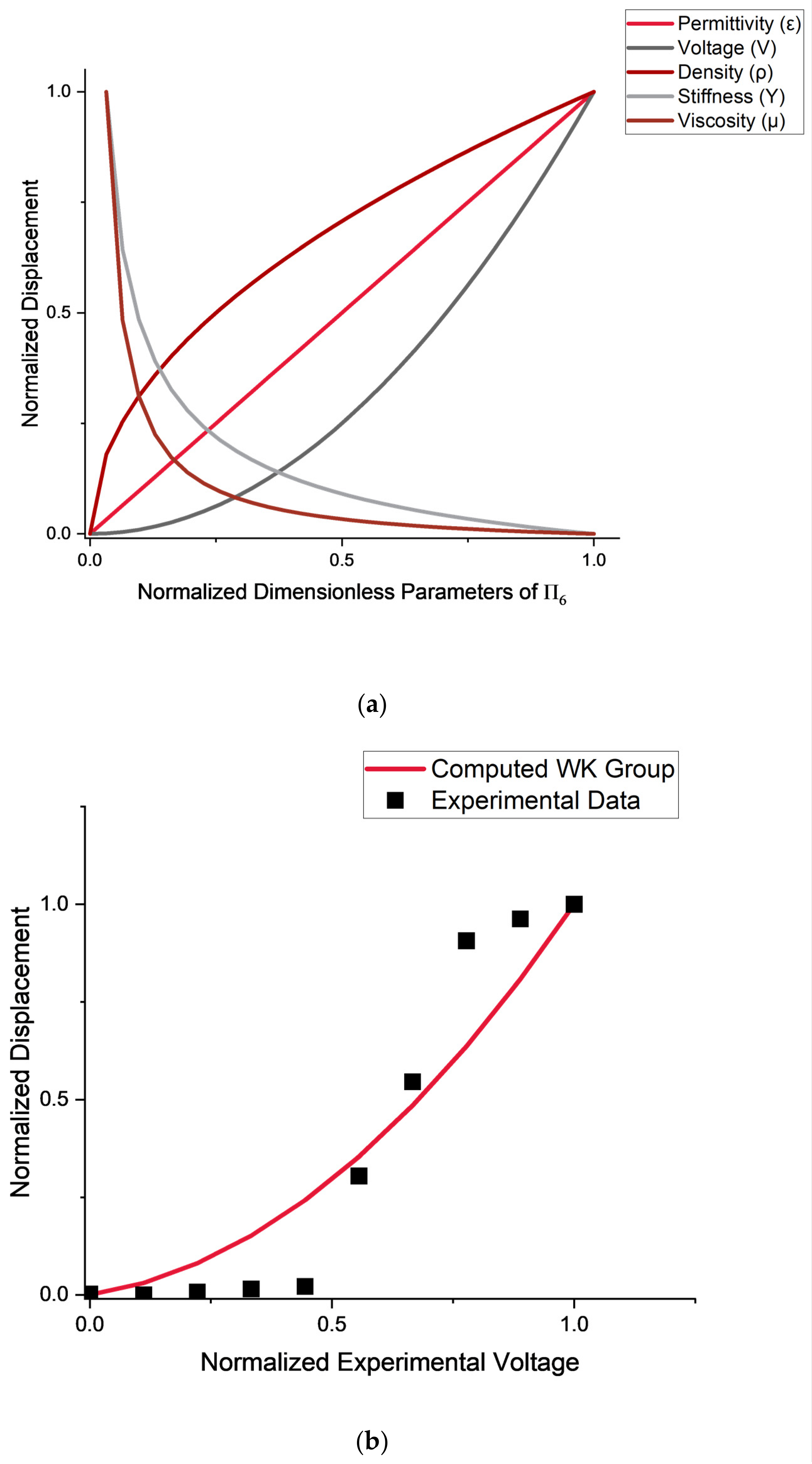
Figure 14a shows the normalized output displacement against the normalized dimensionless parameters of the WK group. From this plot, the contribution of each parameter to the output displacement can be seen. At lower input voltages, the film stiffness and viscoelastic force dominate, resulting in low output (strain and force) from the actuator. However, as the voltage increases the electrostatic force dominates resulting in hydraulic amplification and large outputs. To illustrate this, Figure 14b displays the normalized displacement of the calculated WK and the normalized experimental results. The group was computed using experimental data for LDPE and mineral oil. This relationship is not exactly V2 due to the additional factors such as the viscous forces of the fluid, stiffness of the film, and the three-dimensional edge effects. The contributions of these factors can be seen throughout the data. However, based on the results from the experimental data, the applied voltage is the focus. Future work will quantify the contributions of the other factors. To further illustrate the connection between the electrostatic force and the applied voltage, a statistical significance test was conducted on the correlation coefficient between the experimental data and the WK group (Figure 14b). A correlation coefficient (r2) of 0.6225 was determined [28]. From the statistical significance test, it was determined that there is a strong (p < 0.05) correlation with 62.3% of variance explained (derivation in the Appendix A). Similar to the other Π groups, the stiffness of the film is the next major contribution to the result after the electrostatics. This is also seen in the experimental data.
5.5. Π8 Group: Electrode Geometry Contribution
The final dimensionless group that is important to note is the contribution from electrode geometry. Based on the group alone, it would seem that the sole connection is the mechanical deformation and the movement of the fluid. However, the electrode area is also directly related to the applied force (the electrostatic force), thus this is another electro-mechanical-hydraulic connection. This is not as overtly seen, as with , but the connection can be seen via the analytical equation. The experimental work does not include the electrode geometry as an experimental parameter so a direct correlation cannot be made. However, the dimensionless group gives an indication of what additional parameters can be considered and their effect on the system.
6. Conclusions and Future Work
Through this study, an analytical equation for the zipping of a HASEL actuator was developed. The development of an analytical model increases the understanding of these electrohydraulic actuators. However, due to the complexity of the actuation system, the analytical model in turn is complex and difficult to solve without alternative methods such as finite element analysis. In an effort to understand how each part of the model is affecting the overall system, dimensional analysis techniques were applied to the analytical equation. This study focused on the creation of eight dimensionless groups that indicate the contribution of the various parameters in the analytical equation and connected them to the experimental results. The experimental study focused on testing the material properties of a variety of materials and then relating the material parameters to the output performance and furthermore the analytical equation. All in all, the experimental results showed that a strong, hard, and tough plastic is beneficial for actuator performance and that the fluid parameters can vary. The dimensional analysis was then used to connect these experimental results with the theory. From the analysis, contributions to the output force, the mass flow rate of the fluid, and the applied force were determined amongst others. Based on these dimensionless groups, it was determined that the stiffness of the film is a major contributor overall. In terms of developing electrohydraulic actuators, this is an important parameter to make note of. This result tells us that a shell material of a specific elastic modulus is necessary to have an effective output (displacement and force). Additionally, the viscous force of the fluid is another overall contribution. More specifically the WK group highlighted the contribution of the electrical, mechanical, and hydraulic components of the actuators. Beyond the beneficial relationships determined from the dimensional analysis, the
groups also revealed additional experimental and modeling work that can be conducted to further the understanding of these actuators.
Future work that can aid in the development of EH actuators is experimentally testing the effect of the internal pressure of the fluid. In addition to testing the internal pressure, the effect of the electrode can also be experimentally tested. This includes varying the geometry of the electrode (surface area and thickness) as well as testing various types of electrodes to see how the mechanical performance is altered. In terms of modeling, finite element methods can be applied to this study to determine parameters such as the fluid velocity. However, this study provides a foundation for understanding the essential parameters for EH actuators. By this, actuator performance can be improved for use in robotic systems and demonstrate that EH actuators are a viable solution for practical applications. All in all, dimensional analysis of EH actuators facilitates the development of high-performance HASEL actuators.
Author Contributions
Conceptualization, A.W. and K.J.K.; methodology, A.W.; software, A.W.; validation, A.W., J.S. and K.J.K.; formal analysis, A.W.; investigation, A.W.; resources, A.W.; data curation, A.W.; writing—original draft preparation, A.W.; writing—review and editing, A.W.; visualization, A.W.; supervision, J.S and K.J.K.; project administration, K.J.K..; funding acquisition, K.J.K. All authors have read and agreed to the published version of the manuscript.
Funding
This research was funded by NASA’s Office of STEM Engagement/NASA Fellowship,
grant number 80NSSC20K14720. K.J.K. acknowledges the partial financial support from the US National Science Foundation (NSF),
Partnerships for International Research and Education (PIRE) Program, grant number 1545857.
Any opinions, findings and conclusions or recommendations expressed in this material are those of the author(s) and do not necessarily reflect the views of the NSF.
Data Availability Statement
The data that support the findings of this study are available upon reasonable request from the authors.
Acknowledgments
The authors would like to acknowledge the assistance provided by Zakai Olsen and David James.
Conflicts of Interest
The authors declare no conflict of interest.
Appendix A
Appendix A.1. Electrostatic Force Derivation
In general:
Appendix A.2. Fluid under a Hinged Plate Derivation
First, we consider solving for the average velocity in the x direction. This starts with using the conservation of mass equation.
is the time rate change in mass in the volume, is the mass flow rate in, and is the mass flow rate out.
First, we need to determine the volume under the plate.
The volume is:
The time rate change in mass in the volume:
Conservation of mass:
Now, we want to determine the force of the fluid under the plate. We are only looking at the x and y components.
The shear force components are neglected because the velocity u is only acting in the x direction.
Using integration by parts:
Now, for the y component:
The shear force components are neglected because the velocity u is only acting in the x direction, so the partial derivatives go to zero.
Using integration by parts:
Appendix A.3. Thin Beam in Bending with Large-Deformation Derivation
Integration by parts related to time is conducted.
Next, the potential energy term is determined [18].
From this point, the variation is applied by multiplication, and the integration by parts is conducted to solve.
Once again, the integration by parts is taken again for each integral. The solution for the first integral (highlighted in yellow) is:
The solution of the second integral (highlighted in blue) is:
Thus, providing the final solution:
The whole equation is:
Separating the x and y components:
Appendix A.4. Development of the Π Groups
After the setup of the parameters, the fundamental dimensions, and the repeating parameters is complete, the development of the groups is as follows. The analysis begins with:
where is the non-repeating variable. The steps continue, using the characteristic length as the example:
The exponents can be placed into a system of equations, for further simplification the solution can be using linear algebra techniques.
We now have:
The following script was made in MATLAB to solve the systems of equations easily.
clc;
clear;
% Pi Group Solver
% The repeating parameters matrix
A = [ 1 1 1 1;
2 −1 −1 −3;
−3 −1 −2 0;
−1 0 0 0];
% Inputting the variable for dimensionless group [M; L; T; i]
raw_b = [0;1;0;0];
b = −1 × raw_b;
x = A\b
Appendix A.5. Film Material Thickness
| Film Material | Thickness [mm] |
| BOPP | 0.025 |
| LDPE | 0.050 |
| CPP | 0.100 |
| Ecoflex 00-30 | 0.800 |
Appendix A.6. Correlation Coefficient Calculation and the Statistical Significance Test
To begin, the correlation coefficient between the experimental data and the calculated WK group was determine using the following equation [28]:
where Ye is the estimated/predicted values, is the mean of the sample Y values, and Y is the observed data. This resulted in an r2 value of 0.623. From this point, the t-score was calculated using the following equation [28]:
where r2 is the correlation coefficient and n is the number of sample values. This t-score will be compared to the Student’s t-distribution with n − 2 degrees of freedom at 95% confidence. The calculated t-score is 3.63. At 95% confidence, the t-score from Student’s t-distribution is 2.306. The calculated t-score is greater than the t-score from Student’s t-distribution thus r2 is statistically significant.
Appendix A.7. The Common Nomenclature Used throughout the Text in the Analysis Sections
| Variable | Meaning | Common Units |
| Electric field or electric field through a substance | ||
| Charge | ||
| Vacuum permittivity constant, | ||
| Dielectric constant or relative permittivity | ||
| Surface area of conductive medium or electrode | ||
| Electric field in a vacuum | ||
| Voltage potential | ||
| Capacitance between the electrodes | ||
| Thickness of the film dielectric material | ||
| Thickness of the liquid dielectric material | ||
| The dielectric constant for the film dielectric material | ||
| The dielectric constant for the liquid dielectric material | ||
| The electrostatic potential energy | ||
| The electrostatic force | ||
| The one-dimensional shear stress for a Newtonian fluid with laminar flow | ||
| The fluid velocity in the x direction | ||
| Density of the fluid | ||
| Area of the flow channel | ||
| Angle of the plate | ||
| Time | s | |
| Width of the electrode | ||
| Length of the electrode | ||
| The local thermodynamic pressure | ||
| The maximum thickness of the HASEL actuator above the x-axis | ||
| Mechanical stress | ||
| Young’s modulus | ||
| Strain | ||
| Poisson’s ratio | ||
| Shear modulus | ||
| The beam deflection | ||
| Second moment of inertia | ||
| The mass of the electrode and film | ||
| The first derivative of the beam deflection | ||
| The second derivative of the beam deflection |
References
- McDonald, A.T.; Fox, R.W.; Mitchtell, J.W. Introduction to Fluid Mechanics, 8th ed.; John Wiley and Sons, Inc.: Hoboken, NJ, USA, 2011; Volume 13. [Google Scholar]
- Olsen, Z.J.; Kim, K.J. A hyperelastic porous media framework for ionic polymer-metal composite actuators and sensors: Thermodynamically consistent formulation and nondimensionalization of the field equations. Smart Mater. Struct. 2021, 30, 095024. [Google Scholar] [CrossRef]
- Olsen, Z.J.; Kim, K.J. Characterizing the transduction behavior of ionic polymer-metal composite actuators and sensors via dimensional analysis. Smart Mater. Struct. 2022, 31, 025014. [Google Scholar] [CrossRef]
- Wang, X.; Mitchell, S.K.; Rumley, E.H.; Rothemund, P.; Keplinger, C. High-Strain Peano-HASEL Actuators. Adv. Funct. Mater. 2020, 30, 1908821. [Google Scholar] [CrossRef]
- Rothemund, P.; Kellaris, N.; Mitchell, S.K.; Acome, E.; Keplinger, C. HASEL Artificial Muscles for a New Generation of Lifelike Robots—Recent Progress and Future Opportunities. Adv. Mater. 2021, 33, 2003375. [Google Scholar] [CrossRef] [PubMed]
- Kellaris, N.; Venkata, V.G.; Smith, G.M.; Mitchell, S.K.; Keplinger, C. Peano-HASEL actuators: Muscle-mimetic, electrohydraulic transducers that linearly contract on activation. Sci. Robot. 2018, 3, eaar3276. [Google Scholar] [CrossRef] [PubMed]
- Mitchell, S.K.; Emmett, M.B.; Morrissey, T.G.; King, M.; Keplinger, C.; Benjamin, C.; Radakovitz, M.; Acome, E. Hydraulically amplified self-healing electrostatic actuators with muscle-like performance. Science 2018, 359, 61–65. [Google Scholar] [CrossRef]
- Billah, S.M.R. Dielectric Polymers. In Polymers and Polymeric Composites: A Reference Series; Jafar Mazumder, M., Sheardown, H., Al-Ahmed, A., Eds.; Springer: Cham, Switzerland, 2019. [Google Scholar] [CrossRef]
- Rothemund, P.; Kirkman, S.; Keplinger, C. Dynamics of electrohydraulic soft actuators. Proc. Natl. Acad. Sci. USA 2020, 117, 16207–16213. [Google Scholar] [CrossRef] [PubMed]
- Sundar, V.; Newnham, R.E. Electrostriction and polarization. Ferroelectrics 1992, 135, 431–446. [Google Scholar] [CrossRef]
- Fan, S. Physical properties and basic theory of dielectric. IOP Conf. Ser. Earth Environ. Sci. 2021, 692, 022122. [Google Scholar] [CrossRef]
- Kellaris, N.; Venkata, V.G.; Rothemund, P.; Keplinger, C. An analytical model for the design of Peano-HASEL actuators with drastically improved performance. Extrem. Mech. Lett. 2019, 29, 100449. [Google Scholar] [CrossRef]
- Righi, M.; Fontana, M.; Vertechy, R.; Duranti, M.; Moretti, G. Analysis of Dielectric Fluid Transducers. In Proceedings of the Electroactive Polymer Actuators and Devices (EAPAD) XX, Denver, CO, USA, 5–8 March 2018; SPIE: Denver, CO, USA, 2018; p. 29. [Google Scholar]
- Kanno, R.; Caruso, F.; Takai, K.; Piskarev, Y.; Cacucciolo, V. Biodegradable electrohydraulic soft actuators. Authorea 2022, 1–16. [Google Scholar] [CrossRef]
- Manion, C.A.; Fuge, M.; Bergbrieter, S. Modeling and Evaluation of Additive Manufactured HASEL Actuators. Int. Conf. Intell. Robot. Syst. 2018. [Google Scholar] [CrossRef]
- Anjum, M.N. The HASEL actuator’ s muscle mimicking mechanism for enacting an upper limb smart prosthesis: A review on recent progress and challenges for future implementation. Res. Sq. 2022, 1–17. [Google Scholar] [CrossRef]
- Shapiro, A.H.; Sonin, A.A. Advanced Fluid Mechanics; Self-Published: Cambridge, MA, USA, 2008. [Google Scholar]
- Dowell, E.; McHugh, K. Equations of Motion for an Inextensible Beam Undergoing Large Deflections. J. Appl. Mech. Trans. ASME 2016, 83, 051007. [Google Scholar] [CrossRef]
- Mallick, P.K. Fibre-Reinforced Composites: Materials, Manufacturing and Design; Taylor & Francis Group: Boca Raton, FL, USA, 2008. [Google Scholar]
- Petinrin, O.M.; Adegbola, A.A. Effect of Viscous Dissipation Term on a Fluid between Two Moving Parallel Plates. Ann. Fac. Eng. Hunedoara Int. J. Eng. 2018, 14, 3–6. [Google Scholar]
- Olsen, Z.J. A Hyperelastic Porous Media Framework for Ionic Polymer-Metal Composites and Characterization of Transduction Phenomena via Dimensional Analysis and Nonlinear Regression; University of Nevada-Las Vegas: Las Vegas, NV, USA, 2021. [Google Scholar]
- Buckingham, E. On physically similar systems; Illustrations of the use of dimensional equations. Phys. Rev. 1914, 4, 345–376. [Google Scholar] [CrossRef]
- Jun, S.P.; Kikuchi, K.; Oosato, H.; Nakagawa, H.; Aoyagi, M. Extracting dielectric constant of low-k thin film material for interposer of 3-D multilayer packaging. Proc. Electron. Packag. Technol. Conf. EPTC 2006, 8, 627–634. [Google Scholar] [CrossRef]
- Dielectric Constants of Common Materials. KAB Electro-Acoustics. 2001. Available online: https://www.kabusa.com/Dilectric-Constants.pdf (accessed on 29 February 2019).
- Kiritsakis, A.; Markakis, P. Olive Oil: A Review. Adv. Food Res. 1988, 31, 453–482. [Google Scholar] [CrossRef]
- Garavaglia, J.; Markoski, M.M.; Oliveira, A.; Marcadenti, A. Grape seed oil compounds: Biological and chemical actions for health. Nutr. Metab. Insights 2016, 9, 59–64. [Google Scholar] [CrossRef] [PubMed]
- Yalcin, H.; Toker, O.S.; Dogan, M. Effect of oil type and fatty acid composition on dynamic and steady shear rheology of vegetable Oils. J. Oleo Sci. 2012, 61, 181–187. [Google Scholar] [CrossRef] [PubMed]
- Alder, H.L.; Roessler, E.B. Introduction to Probability and Statistics, 3rd ed.; W.H. Freeman: San Francisco, CA, USA, 1964. [Google Scholar]
Figure 1.
Example of a HASEL actuator created in the lab. The actuator pictured has a carbon tape electrode, a low-density polyethylene shell, and is filled with mineral oil.
Figure 1.
Example of a HASEL actuator created in the lab. The actuator pictured has a carbon tape electrode, a low-density polyethylene shell, and is filled with mineral oil.

Figure 2.
The HASEL actuation mechanism. (Top) The inactive actuator. (Middle) The actuator has been activated and the critical draw-in voltage has been reached, thus the zipping of the electrode has begun. (Bottom) Full draw-in of the electrodes has occurred and a majority of the liquid dielectric has been displaced causing the expansion of the film shell. This creates an output displacement and force.

Figure 3.
Fluid dynamics model setup for fluid under a hinged plate.

Figure 4.
Solid mechanics model setup for a beam in bending undergoing large deflections.

Figure 5.
The connection of the electrostatics, fluid dynamics, and solid mechanics in the analytical equation.
Figure 5.
The connection of the electrostatics, fluid dynamics, and solid mechanics in the analytical equation.

Figure 6.
The 3D render of an approximate Peano-HASEL actuator as described by the analytical equation.
Figure 6.
The 3D render of an approximate Peano-HASEL actuator as described by the analytical equation.

Figure 7.
Young’s modulus values for each material and its orientation material.

Figure 8.
The dielectric constant values of the film materials at laboratory temperature, 20 °C.

Figure 9.
The experimental viscosity data of the liquid dielectric materials at laboratory temperature 20 °C.
Figure 9.
The experimental viscosity data of the liquid dielectric materials at laboratory temperature 20 °C.

Figure 10.
The experimental performance testing setup. (a). The testing setup for measuring the displacement. (b). Testing setup for measuring the force using the load cell. (c). Testing setup for measuring the lifting force.
Figure 10.
The experimental performance testing setup. (a). The testing setup for measuring the displacement. (b). Testing setup for measuring the force using the load cell. (c). Testing setup for measuring the lifting force.

Figure 11.
The compiled strain–voltage data organized by the Film Type. A second order polynomial fit (y = ax2 + bx + c) is applied to the data to illustrate the V2 relationship.
Figure 11.
The compiled strain–voltage data organized by the Film Type. A second order polynomial fit (y = ax2 + bx + c) is applied to the data to illustrate the V2 relationship.

Figure 12.
The compiled pressure–voltage data organized by the Film Type. A second order polynomial fit (y = ax2 + bx + c) is applied to the data to illustrate the V2 relationship.
Figure 12.
The compiled pressure–voltage data organized by the Film Type. A second order polynomial fit (y = ax2 + bx + c) is applied to the data to illustrate the V2 relationship.

Figure 13.
The maximum displacement of the loaded actuators at 9 kV.

Figure 14.
(a). The normalized output displacement against the normalized dimensionless parameters of the WK group (Π6). The figure illustrates how the displacement is affected as each parameter gets larger. (b). The normalized output displacement from the computed WK group (Π6) against the normalized experimental voltage. The WK group (Π6) was computed using experimental data (LDPE and olive oil).


Table 1.
Dimensional Analysis Definitions and Setup.
| Variables | Meaning | Dependence | |
|---|---|---|---|
| Characteristic length | D | ||
| Fluid velocity | D | ||
| Fluid pressure | D | ||
| Second moment of inertia | I | ||
| Area of the electrode | I | ||
| Mass of the electrode and film | I | ||
| Young’s modulus | I | ||
| Acceleration due to gravity | I | ||
| Fluid density | I | ||
| Dynamic viscosity of the fluid | I | ||
| *ε | The permittivity | D/I | |
| CoV | Applied voltage | I |
Table 2.
List of Π Groups.
| Dimensionless Group | Physical Meaning |
|---|---|
| The mass flow rate contribution and the viscous force contribution. Related to the displacement of the fluid. | |
| The fluid velocity contribution as it relates to the density and film stiffness. | |
| The output force contribution. | |
| Film/electrode geometry contribution, thus a solid–fluid interface connection. | |
| The gravity contribution. | |
WK Group | The electrostatic contribution and its relationship to the viscous forces and material stiffness, the electro-mechanical-hydraulic connection. |
| The mass contribution of the film/electrode. | |
| The electrode geometry contribution, this is a direct solid–fluid interface connection and an indirect electro-mechanical connection. |
Disclaimer/Publisher’s Note: The statements, opinions and data contained in all publications are solely those of the individual author(s) and contributor(s) and not of MDPI and/or the editor(s). MDPI and/or the editor(s) disclaim responsibility for any injury to people or property resulting from any ideas, methods, instructions or products referred to in the content. |
© 2023 by the authors. Licensee MDPI, Basel, Switzerland. This article is an open access article distributed under the terms and conditions of the Creative Commons Attribution (CC BY) license (https://creativecommons.org/licenses/by/4.0/).
Share and Cite
MDPI and ACS Style
Washington, A.; Su, J.; Kim, K.J. Actuation Behavior of Hydraulically Amplified Self-Healing Electrostatic (HASEL) Actuator via Dimensional Analysis. Actuators 2023, 12, 208. https://doi.org/10.3390/act12050208
AMA Style
Washington A, Su J, Kim KJ. Actuation Behavior of Hydraulically Amplified Self-Healing Electrostatic (HASEL) Actuator via Dimensional Analysis. Actuators. 2023; 12(5):208. https://doi.org/10.3390/act12050208
Chicago/Turabian StyleWashington, Alexandrea, Ji Su, and Kwang J. Kim. 2023. "Actuation Behavior of Hydraulically Amplified Self-Healing Electrostatic (HASEL) Actuator via Dimensional Analysis" Actuators 12, no. 5: 208. https://doi.org/10.3390/act12050208
Note that from the first issue of 2016, this journal uses article numbers instead of page numbers. See further details here.