
Evaluation of Spiral Pneumatic Rubber Actuator Using Finite Element Analysis for Radial Transportation


Department of Mechanical Engineering, School of Engineering, Tokyo Institute of Technology, 2-12-1 Ookayama, Meguro-ku, Tokyo 152-8552, Japan
*
Author to whom correspondence should be addressed.
Actuators 2023, 12(5), 205; https://doi.org/10.3390/act12050205
Submission received: 19 April 2023
/
Revised: 15 May 2023
/
Accepted: 16 May 2023
/
Published: 17 May 2023
(This article belongs to the Special Issue Recent Advances in Pneumatic Soft Actuators)
Abstract
:Emerging actuators with various soft materials and a traveling wave motion are frequently discussed. Various configurations have been proposed and their resulting performances investigated, but it remains challenging to realize large strokes. This study presents an experimentally validated nonlinear finite element model to predict the deformation produced by a spiral pneumatic rubber actuator to generate a traveling wave motion. The actuator consists of a membrane mounted on a rubber substrate with three air chambers in a spiral configuration. The sequential deformations of the successive chambers interact with each other and produce radial traveling waves on the membrane surface, driving the objects placed on the actuator. Finite element analysis with ANSYS computer software was used to analyze the elastic movement by considering the influence of different initial structural types. The simulation results indicated an optimal structure with specific ratios. A reasonable correlation was obtained during experimental validation; the predicted displacement values were approximately 17% smaller than the experimental values. Finally, the transportation performance of the prototype was tested, and a velocity of 2.28 mm/s in the desired direction was achieved. We expect that our demonstration will expand the range of applications of the spiral pneumatic rubber actuator to include conveying or worm-like robots.
1. Introduction
Pneumatic actuators are extensively used in soft robotics owing to their simple design, structure, and driving principles. Due to their pliant bodies and flexible transformation, soft pneumatic actuators move effectively in complex environments and are predicted to be able to accomplish tasks in difficult terrain and safely interact with humans [1]. Additionally, pneumatic rubber actuators are able to function in both wet and dry environments.
Compliant mechanisms are often inspired by the morphology and functionality of biological agents and are widely used in the design of robots and devices. A traveling wave operation, inspired by natural creatures such as earthworms, snails, and snakes, is an effective movement method. The applications of pneumatic actuators include conveyance devices [2], microrobots [3], peristaltic pumps [4], annelid robots [5], and piezoceramics [6]. The actuators have multiple active regions in a single controllable device; thus, peristaltic motion is manifested by cycling these active regions. This configuration has been extensively used in piezoceramic devices such as conventional ultrasonic motors. Poole et al. [7] presented a crawling actuator using multi-stack dielectric elastomers to generate locomotion based on the sequential actuation of the segments; however, the maximum attainable velocity was 2.1 mm/min, which was commercially insufficient.
It is very challenging for soft actuators to realize fast locomotion. However, soft actuators driven by pneumatic pressure are promising because of their advantages such as a large deformation and a high output-to-weight ratio. To generate a traveling wave using air pressure, multiple chambers are pressurized with a certain phase difference, which results in the desired output motion [8,9]. Suzumori [10] presented a pneumatic rubber actuator comprising a rubber slab with deformable hollow chambers to produce linear motion on its surface. A walking speed of 4.7 mm/s was obtained from the prototype tests. However, the structure had multiple fins on its surface to generate a traveling wave motion; thus, limitations exist for the shape of objects that can be transported. Furthermore, a soft pneumatic mobile robot [11] was developed with flexible flat tubes. The prototype produced self-excited vibration for a traveling wave motion to propel through a narrow space with the designed gap. The actuator had a locomotion speed of 3.2 mm/s and could be adjusted with the supply pressure. However, it was necessary to adopt a 3D structure for the airflow path to connect pressure supply hoses with each chamber, which hindered movement and added to production complexity.
A traveling wave motion can simultaneously provide large strokes and high forces with appropriate materials and perfectly configured actuation systems. The desired motion is achieved by predefining the layout and actuation patterns. The output comes from two processes: the production of traveling waves on the surface and the transfer process at the contact interface. A multi-stack dielectric elastomer actuator can travel between two planar surfaces by cycling active stacks [7]. The parallel stacks are expanded in the planar direction and compressed in the perpendicular direction, thereby repeating locomotion and gripping the friction surface. Qi et al. [8] proposed a soft pneumatic snake robot to move in complex, constrained environments using a traveling wave motion. Connolly et al. [12] developed a soft fluidic actuator with a segmented structure for crawling. In addition, in [13], a fluidic pump consisting of helical electrodes embedded within the walls of a polyurethane tube was designed to generate continuous fluid flow. Ran et al. [14] developed a miniature piezoelectric actuator without a tooth structure on the stator surface to drive actuation. These actuators were controlled by a single device by designing ports to supply independently applied signals. However, the devices tended to be composed of three or more segments, which made it difficult to build input signal paths on planar structures.
Moreover, the use of structural calculation software is now a common practice when modeling and analyzing compliant mechanisms that are highly nonlinear. To adequately predict behavior, many methods have been developed to incorporate the elastic property into kinematic analysis. A popular approach to model continuum mechanisms is finite element analysis (FEA), in which the finite element meshed model is analyzed; thus, the detailed displacement and stress can be calculated for each element. With this significant advantage, any complex structure that can be employed as a meshed model can be generated from a meshing algorithm. Bieze et al. [15] have modeled soft continuum manipulators to obtain forward and inverse kinematic models under quasi-static conditions. Sun et al. [16] integrated the FEA-based mechanics modeling of large displacements, tendon-drive mechanisms, and contact problems. Other methods include the precise constant curvature model (PCCM) and the pseudo rigid body model (PRBM). The PCCM method is suitable for soft mechanisms with snake-like geometries [17] as each bent section can be modeled as an arc with constant curvature. Using the PRBM method, flexible parts with a large deflection can be modeled based on the classic rigid-joint mechanism [18]. To apply PRBM, flexure hinges must be determined manually for model simplification; thus, the detailed stress cannot be obtained.
In the present study, a spiral pneumatic rubber actuator is proposed, which utilizes an Archimedean spiral configuration [19] to develop three airflow paths on a planar surface. The sequential deformations of the successive chambers interact with each other and produce radial traveling waves on the membrane surface, which sort objects by size or align them with the center. The goal is to establish a structural model, estimate the displacement, and optimize the design parameters to generate radial transportation with large strokes. The model is designed using three equidistant active segments with several parameters: membrane thickness, chamber width, chamber depth, and wall thickness. In addition, the effects of the structural parameters on actuation are investigated using 2D and 3D finite element models and then verified experimentally based on observations.
The remainder of this paper is organized as follows: Section 2 presents an overview of the proposed actuator’s design, operating principles, and fabrication. Section 3 explains the theoretical models and methods used for FEA. Section 4 presents the prototype testing to assess its performance characteristics and confirm the theoretical model’s validity. Finally, Section 5 concludes this study.
2. Design and Fabrication
2.1. Structural Design
The spiral actuator, shown in Figure 1, comprises a silicone membrane mounted on an elastic substrate. Internal walls divide the actuator interior into three inflatable air chambers. The Archimedean spiral configuration is introduced to generate an inflatable shape at an equal distance from the surface during actuation. The rectangular cross-section allows the input air pressure to act on the membrane surface and internal free walls of the chambers. In Figure 1b, a and b represent the width and depth of the chamber, respectively, and c and t describe the wall and membrane thicknesses, respectively.
2.2. Actuator Principle
The relatively thin internal walls deform freely owing to the internal pressure difference in the air chambers. In addition, there is a shift in the center position of the pressurized membrane because of the elastic force caused by the bending motion of the walls and the initial pressure; thus, x- and y-axis displacements are generated. A schematic of the actuator used to induce a traveling wave motion is shown in Figure 2. The green arrows indicate the deformation caused by the applied air pressure, and the red arrows indicate the deformations contributing to the transportation of the object.
In Step 1, chamber A is pressurized, causing the membrane to inflate and the walls of the substrate to bend outward. When air pressure is applied to adjacent chamber B in Step 2, the wall between A and B returns to its original position and the elastic force pushes the membrane of chamber A to the left. In Step 3, chamber A, which inhibited the deformation of chamber B, becomes inactive, and the chamber B membrane is pushed to its center. Next, Step 4 proceeds through Steps 5, 6, and 1 using the same process. By repeating these steps, the actuator continues to deform and realize transportation. To achieve this process, periodic pressure signals are applied with a certain operating frequency to pressurize each chamber. Here, the operating frequency is calculated from the time per cycle for chamber A to reactivate; that is, it is the reciprocal of the time from Step 1 to Step 6.
2.3. Fabrication
Figure 3 shows the three main steps in the fabrication process. A high-precision silicone membrane (ELASTOSIL® Film 2030, Wacker Chemie AG, Dalton, GA, USA) was cut into sufficiently large pieces to cover the substrate while keeping the surface clean.
The rubber substrate was made by pouring liquid silicone (KE/CAT–1600, Shin-Etsu Silicone, Akron, OH, USA) into a mold. The mold was produced with specific dimensions using a polyjet 3D printer (Stratasys Objet260 Connex3, Stratasys, Austin, TX, USA). The material used was VeroWhite photosensitive resin. The two-component liquid silicone was mixed in a mass ratio of 1:1 and thoroughly agitated using a mixer (ARV–310P, Thinky, Tokyo, Japan). There were two stages of mixing: 30 s at 2000 rpm and 45 s at 2200 rpm. After de-aeration in a vacuum chamber, the rubber was cured at 18 °C for 24 h to maintain constant flexibility properties.
Plasma treatment equipment (CIONE 4, Femto Science Inc., Somerset, NJ, USA) was used for direct bonding via atmospheric plasma treatment. While maintaining the air flow rate at 10 sccm (standard cubic centimeters per minute), plasma was obtained at a predetermined pressure of 7.6 × 10² Torr (101 kPa) with a radio frequency power of 100 W. The base pressure was maintained at less than 5.0 × 10⁻² Torr (6.67 kPa), and the plasma exposure time was set to 30 s.
The above process resulted in an actuator made entirely of soft material. The three interior chambers were connected by three air hoses and had independent movement.
3. Finite Element Simulations
3.1. FEA Model of Spiral Actuator
The FEA of the designed actuator was performed using ANSYS 2023R1 software. Optimization was used to determine the structural parameters of the spiral actuator that maximized its output deformation. The displacement trajectories were analyzed via static structural analysis using the ANSYS Workbench. The material properties were modeled as hyperelastic, incompressible materials using the YEOH strain energy functions [20]:
where W is the strain energy density; C10, C20, and C30 are the material properties; and I1 is the first invariant of the left Cauchy–Green deformation tensor.
For the silicone membranes, the material constants of C10, C20, and C30 were 0.1811, −0.01598, and 0.00629 mPa, respectively [21]. The rubber substrate was assumed to have a density of 1.27 g/cm3, hardness of 45 (Type A durometer), and tensile strength of 6.5 mPa.
The Archimedean spiral structure has a large longitudinal dimension, which makes it suitable for use in the 2D plane strain model in the present study, as shown in Figure 4. Several structural parameters were defined, as listed in Table 1, to investigate the influence of the initial structural type on actuation. The air chamber width a was kept constant so that other candidate parameters in the optimization model could be expressed in terms of membrane thickness t and length dimensions b and c at several ratios: t/a, b/a, and c/a. The distance between the rubber base and chamber was fixed at 2 mm. The base of the rubber substrate was fixed, and the other surfaces were set to the free boundary condition. The simulations were performed under an input air pressure of 80 kPa.
To evaluate the spiral actuator’s deformation behavior and driving performance, we developed a procedure using two FEA simulations. The first simulation predicted the directional displacement along the y-axis for a pressurized membrane at the center point. The second simulation predicted the x-axis displacement produced by elastic deformation when adjacent segments were simultaneously pressurized. Displacement along the x-axis is important because it contributes to the transpiration performance of the object.
3.2. Effect of Structural Parameters
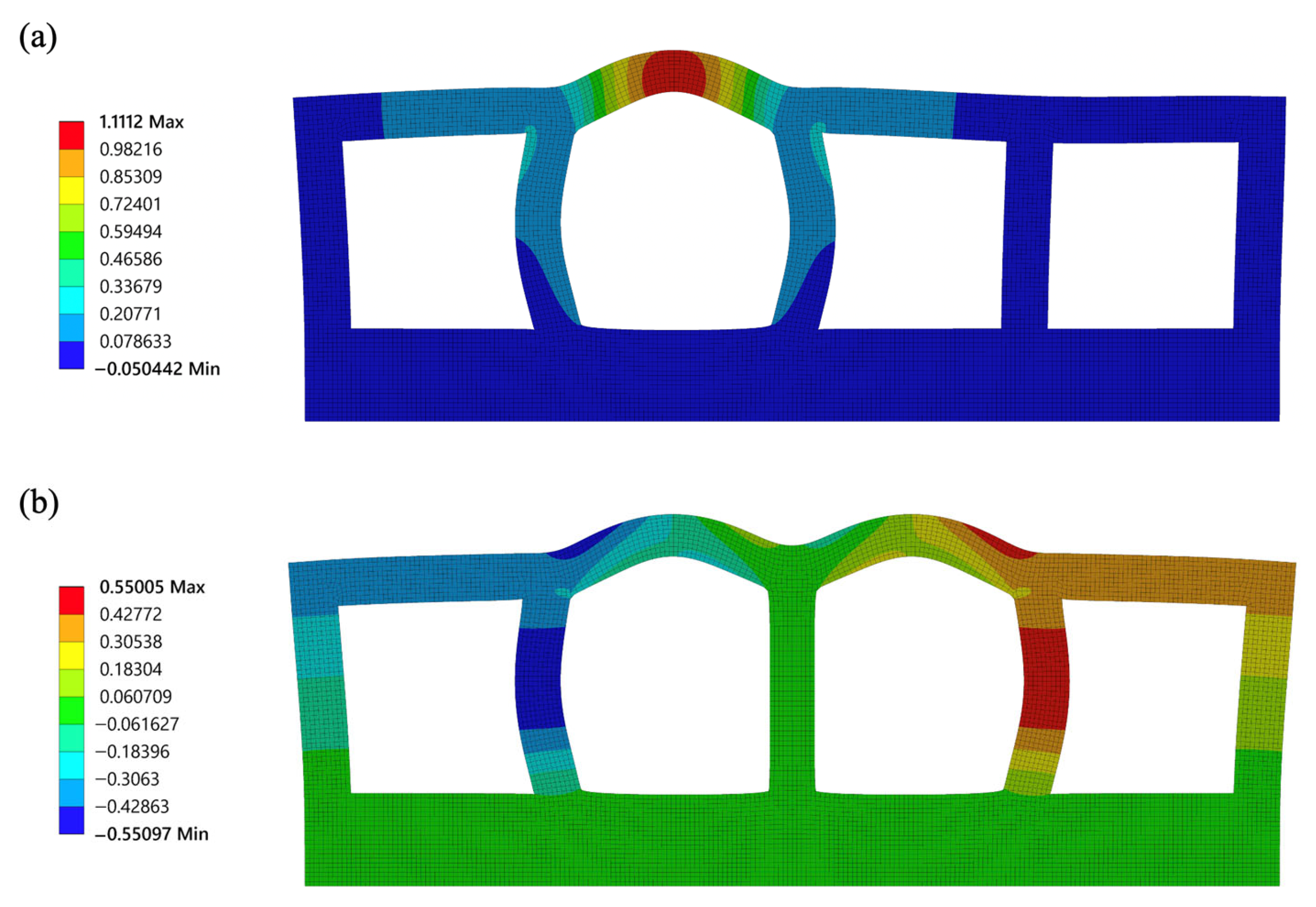
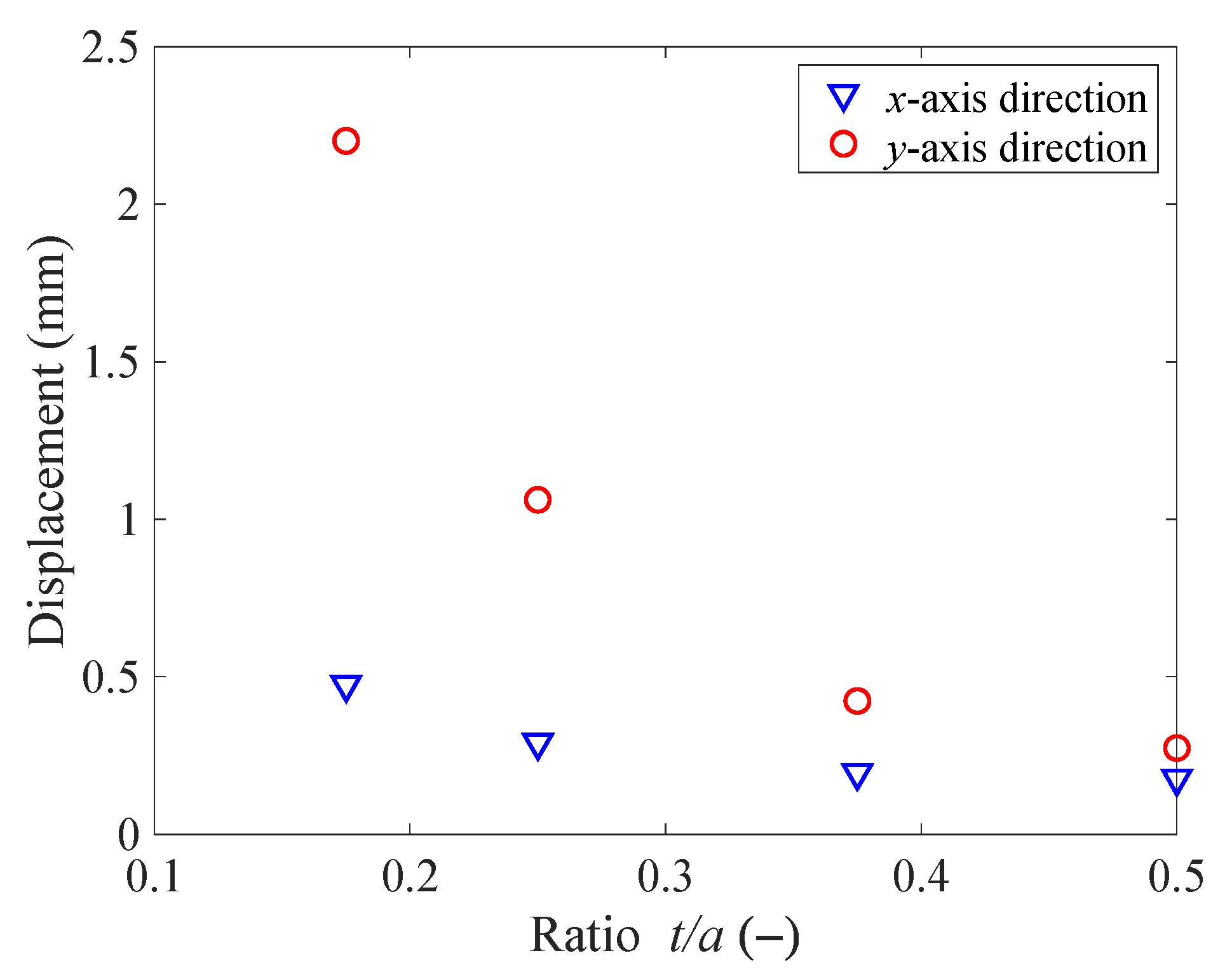
The element was a 0.1 mm four-node rectangular. An example of the FEA simulation results is shown in Figure 5 for t = 1, b = 4, and c = 1. The predicted deformations with respect to the ratio parameter t/a are shown in Figure 6: as t/a increases, the deformation decreases. A smaller membrane thickness reduces the bending stiffness, which improves the actuator swell in a pressurized state. However, when the thickness is considerably reduced, the y-axis displacement exceeds the size of the actuator, but the effect on the x-axis displacement is small.
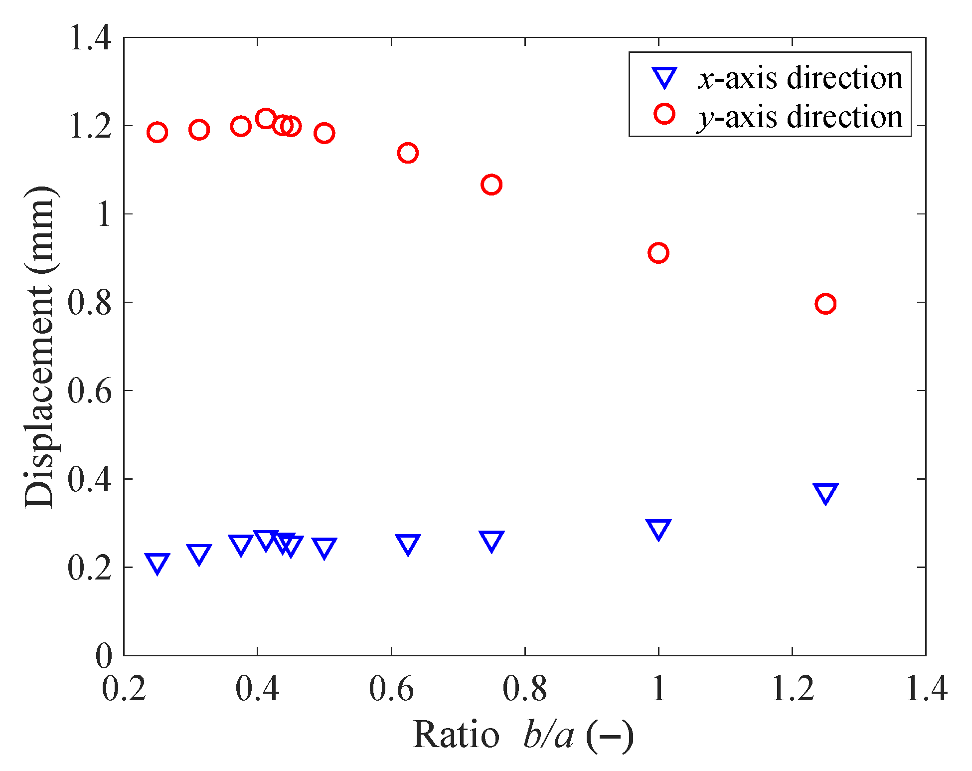
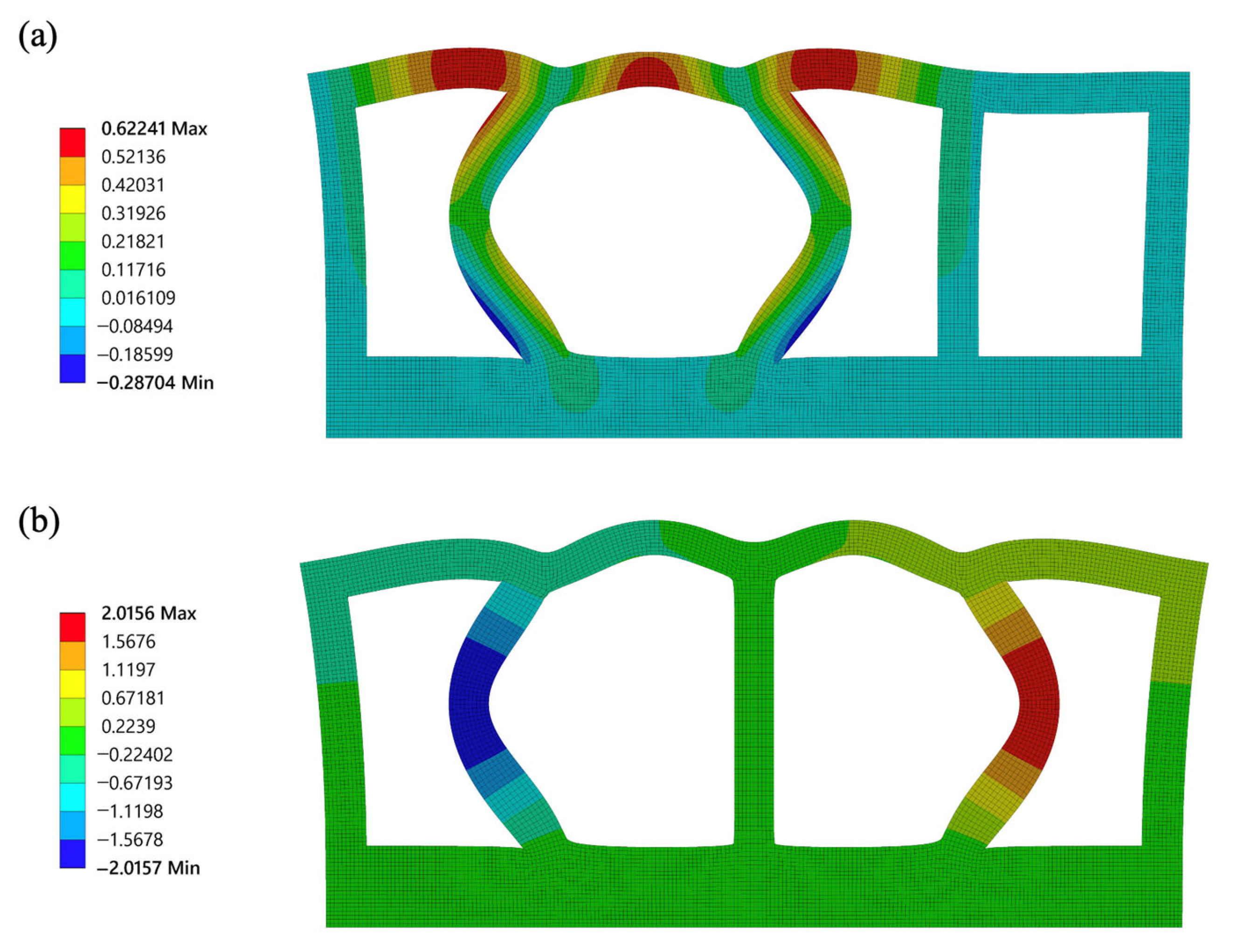
Displacements with respect to the ratio b/a are shown in Figure 7. For b/a ≤ 0.4, an increase in the air chamber depth increases the deformation, producing larger displacements under both operating conditions. When b/a > 0.4, the wall bending increases, which increases the x-axis displacement and lowers the membrane position along the y-axis. This is the optimal condition for activating transportation. However, there is an optimal value for the chamber. When b/a > 1.3, the center position of the membrane in a highly pressurized chamber becomes lower than the center position of the membrane in the other chambers, owing to excessive wall bending, and the actuator fails to transport the object placed on its membrane surface. An example of this type of failure occurring in an FEA simulation is shown in Figure 8.
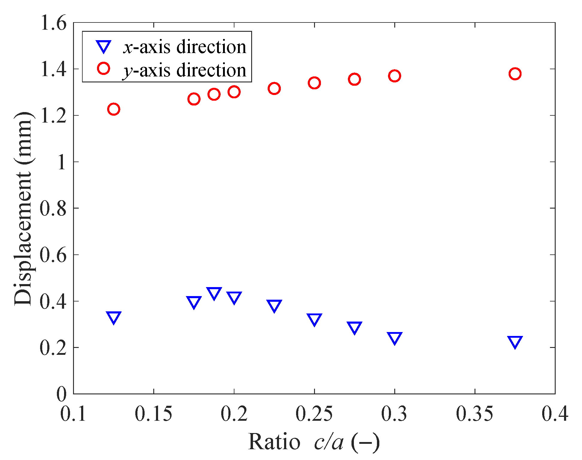
The effect of the ratio c/a on displacement is shown in Figure 9. As c/a increases, the y-axis displacement increases in relatively small increments. However, for the x-axis displacement, the peak value is obtained at approximately c/a = 0.19, which is the optimal condition for object transportation; that is, an optimal structure exists to obtain a large displacement in the x-axis direction for realizing effective transportation.
4. Experiments and Discussions
4.1. Experimental Apparatus and Method
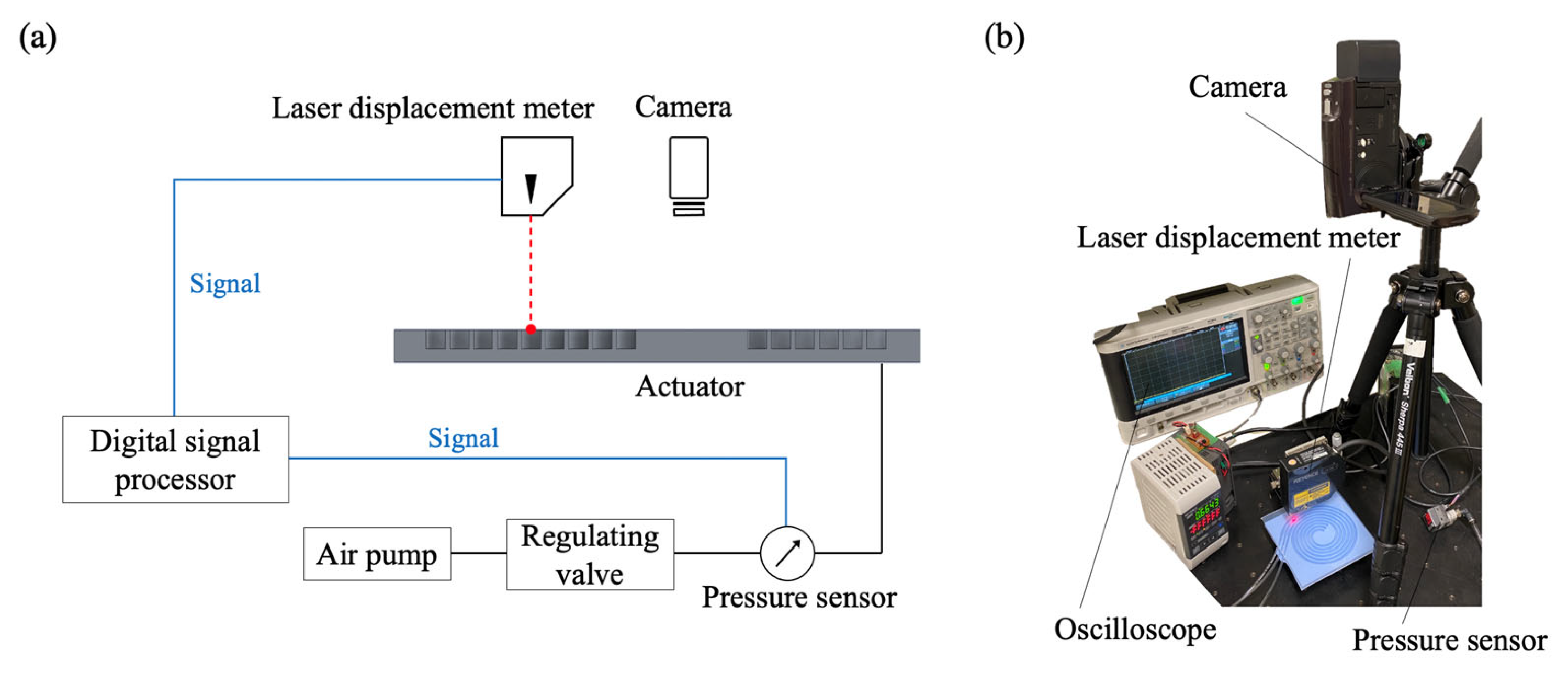
Following the FEA simulations, a prototype actuator was prepared for experimental validation. The experimental setup is illustrated in Figure 10. Air pressure was supplied to expand each chamber and maintain the pressure constant; the pressure was measured using a pressure sensor (AP-C33, Keyence). The operating frequency was changed manually during the experiment and obtained from the pressure signals recorded using an oscilloscope. The laser displacement meter (LK-G32, Keyence) displaced a point on the actuator; the resulting deformation was immediately recorded using a video camera.
4.2. Experimental Validation
Deformation tests were performed using a prototype with a, t, b, and c set at 4, 1, 4, and 1 mm, respectively. The deformations were predicted using 2D and 3D finite element models and compared with the experimental results.
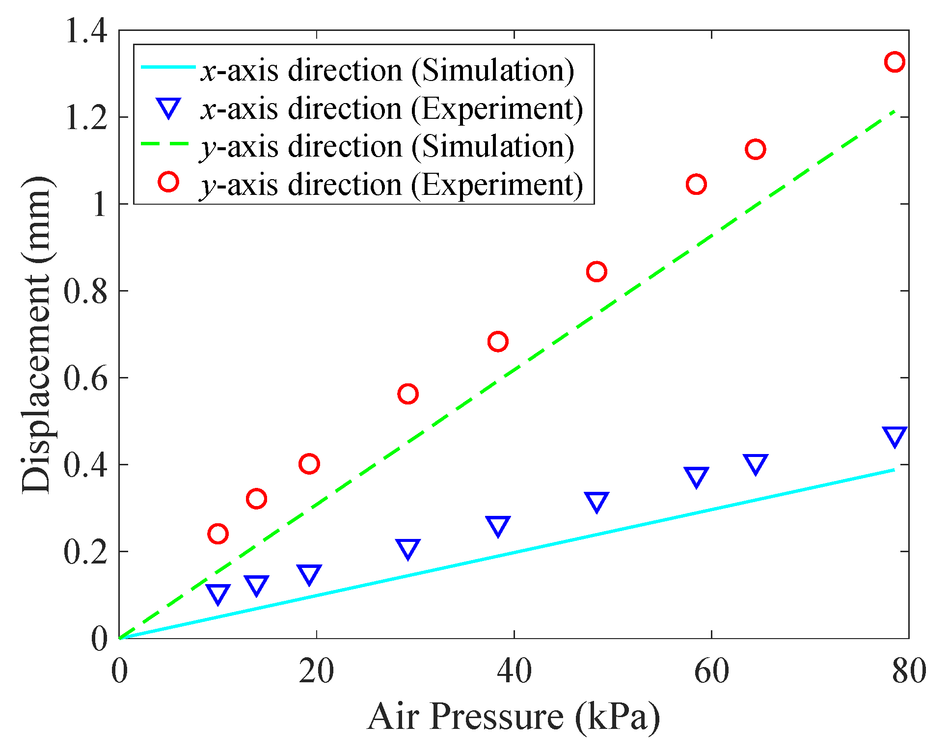
The results are presented in Figure 11 using an operation frequency of 0.32 Hz for the 2D finite element model. The deformations of the actuator increase linearly with the air pressure, and the y-axis displacements are considerably larger than those of the x-axis. The results have a reasonable correlation, indicating the validity of the modeling method. The simulation and experimental results show an x-axis displacement of 0.39 and 0.47 mm, respectively, under an air pressure of 78.5 kPa. The y-axis deformation is 1.21 and 1.32 mm in the simulation and experimental results, respectively. Although the growth tendency is similar, the predicted deformations were smaller probably because of the assumption of uniform wall thickness and errors in the stiffness of the simulated actuator. However, fabrication processes or errors in the material properties can cause changes in wall thickness or stiffness coefficients.
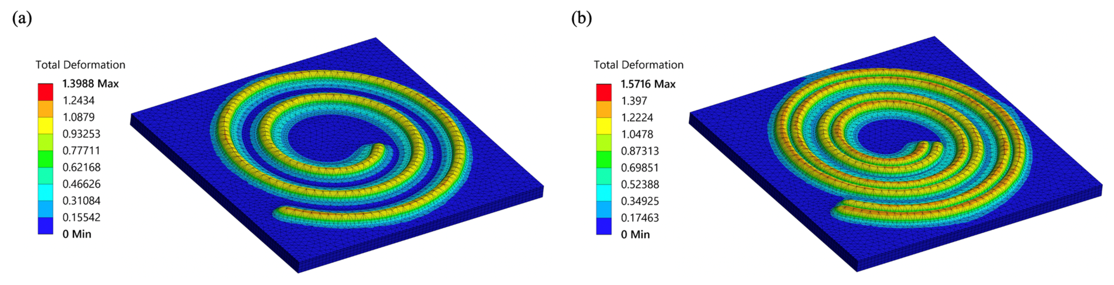
The deformation results obtained from the simulation using the 3D finite element model are shown in Figure 12. Boundary conditions were applied to the meshed model, in which the lower surface of the rubber substrate was fixed, and 80 kPa of pressure was distributed uniformly on all chamber surfaces. When one chamber was pressurized, as shown in Figure 12a, the displacement was concentrated at the center of the membrane. When the two successive chambers were pressurized, as shown in Figure 12b, the deformation was concentrated in and around the center of the membrane. This indicates that the deformations in the two adjacent chambers affect each other and contribute to the transportation of the object, as shown in the 2D model evaluation.
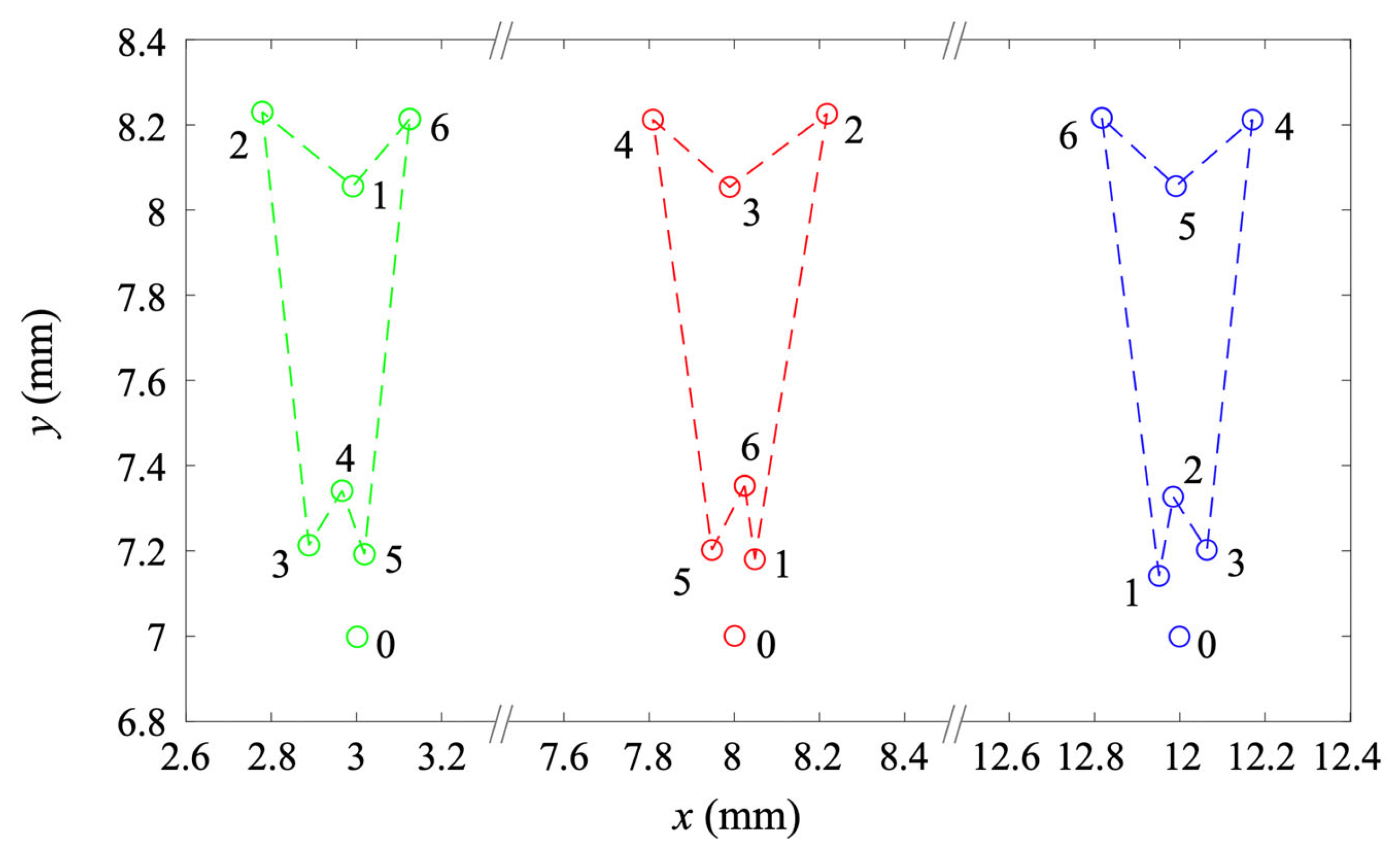
Figure 13 shows the behavior of the top position on each membrane. The tracking results were obtained from 3D FEA with the same boundary condition and air pressure value. Each state number is indicated in response to an applied pressure signal from an inactive state (labeled 0) to an active state (labeled 1–6), corresponding to that in Figure 2. When a sequential stimulus is applied, the top points of the pressurized membrane were pushed in the negative x-direction, thus causing the contacted object to advance backward. This indicates that the movement interfering between successive segments can contribute to the transport. Furthermore, a small displacement along the positive x-direction induced by the wall deformations was observed for inactivated segments. However, these changes were negligible compared to the displacement at pressurized states, and the interaction between the chambers was sufficient.
4.3. Transportation Experiments
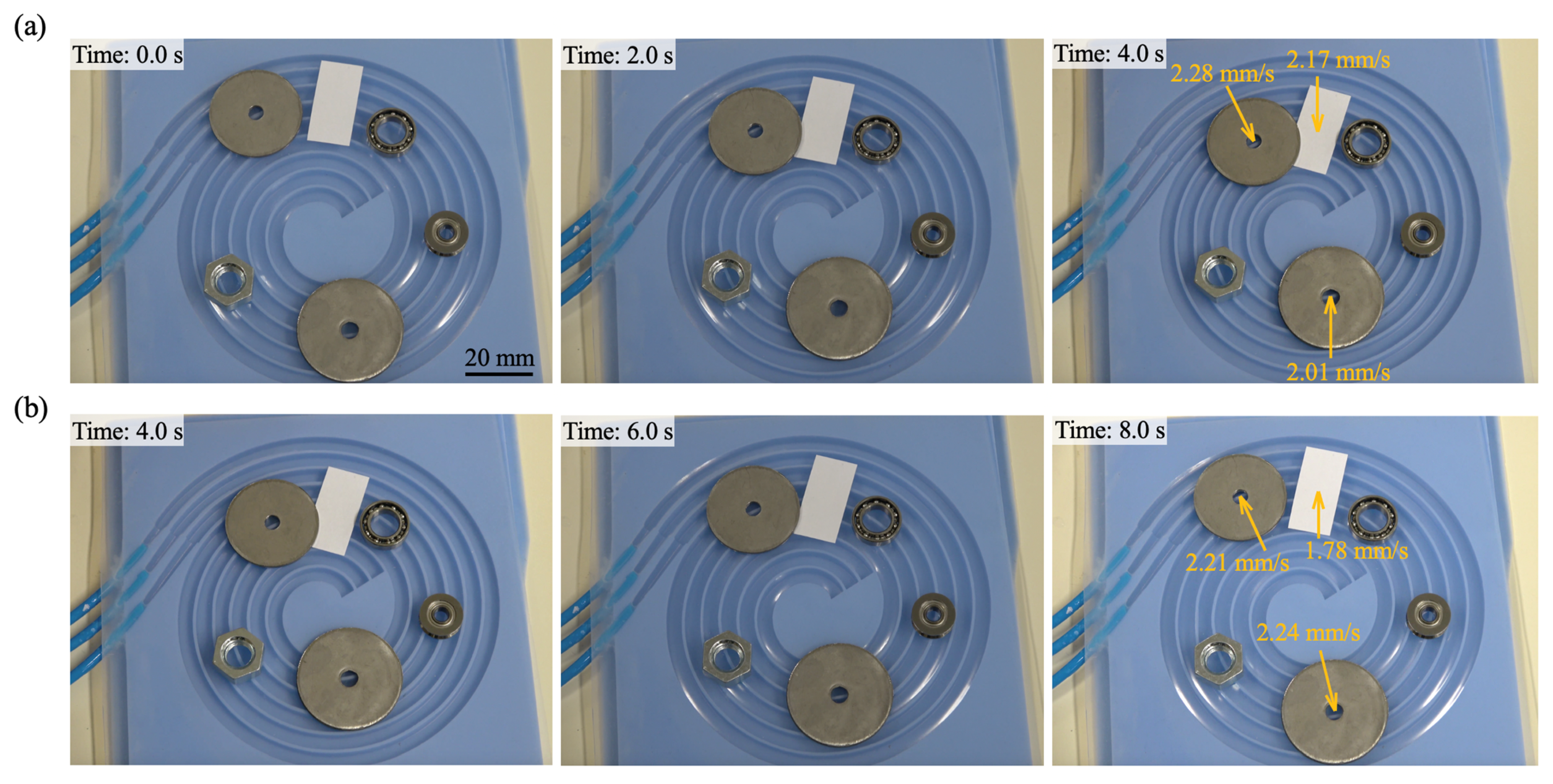
A transportation test of the spiral actuator was performed to evaluate its ability to perform spiral transportation and determine its velocity. The sequential deformation of successive chambers generated traveling waves on the surface, facilitating the transportation of objects. The maximum velocity obtained was 2.28 mm/s at an air pressure of 78.5 kPa at 10 Hz. Figure 14 shows objects on the actuator moving in the desired direction.
However, when comparing the results of the transportation experiments for objects of different sizes and weights, it was indicated that a minimum size exists for conveying. The objects were found to need effective contact with at least two consecutive chambers to be transported according to the actuation principle proposed. In practice, relatively large washers and paper covering two or more chambers were repeatedly transported. The yellow arrows indicate the direction and speed of each successfully transported object. However, for smaller size objects for which size does not span the traveling wave deformation region contributing to the transportation, there was little or no movement. The weight of the objects did not have a significant impact.
5. Conclusions
A spiral pneumatic actuator consisting of a thin film and an elastic substrate with an Archimedean spiral configuration was developed to generate a traveling wave motion for radial transportation. FEA simulations and experimental studies determined the deformation performance with different structural parameters for various predictable structures. The model was designed using three equidistant active segments with several parameters: membrane thickness, chamber width, chamber depth, and wall thickness. A reasonable correlation was obtained between the simulation and experimental results. The maximum deformation of the actuator was obtained considering three structural ratios: t/a, b/a, and c/a. The simulation results predicted the x- and y-axis displacements for each structure and suggested the optimal structure condition to obtain a larger stroke. A spiral configuration was introduced for ease of production, and we proposed a structure that can be applied to a variety of traveling wave actuators to evaluate their displacements. This concept can serve as a platform for other applications, such as conveying devices and crawling robots.
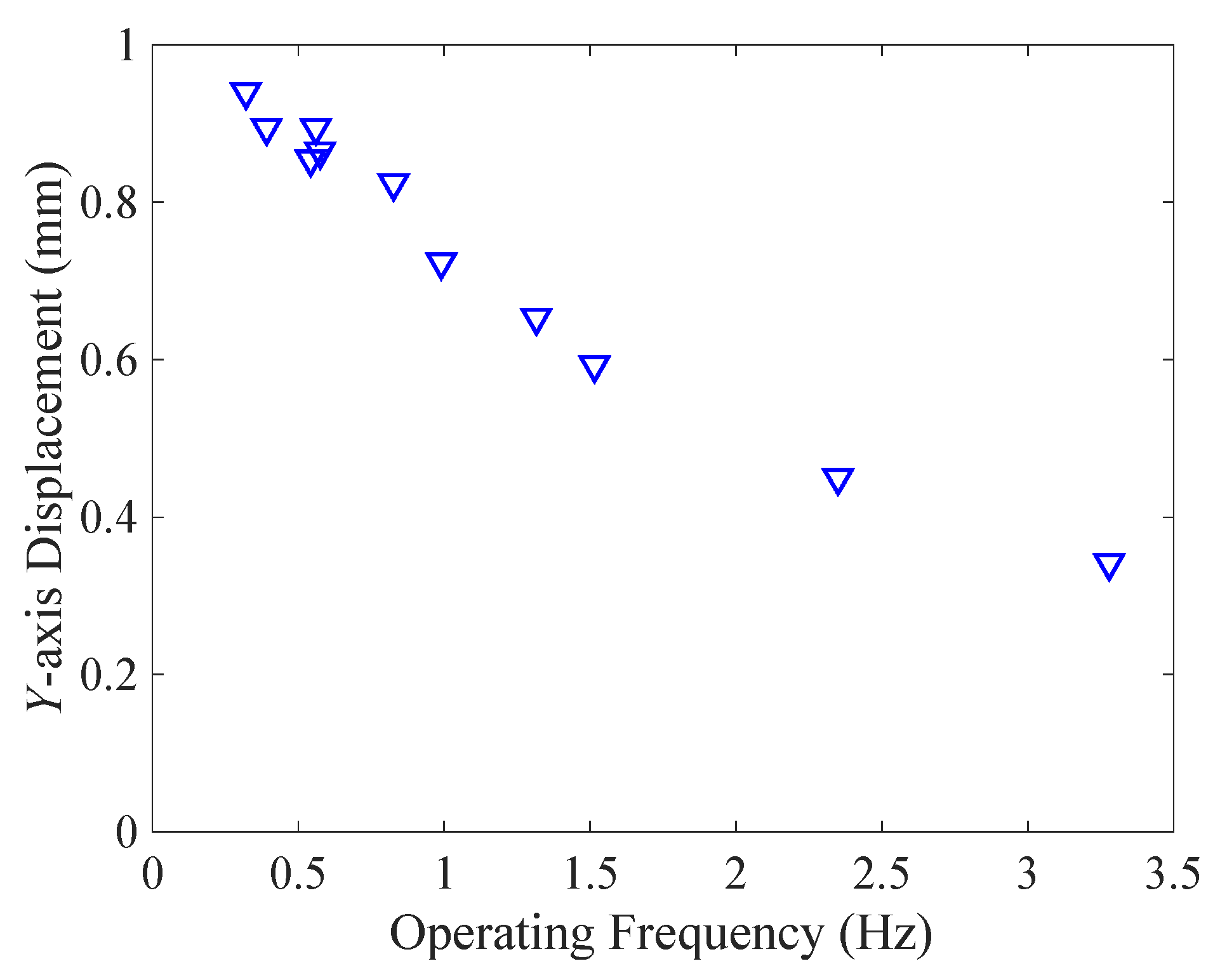
This actuator still has room for improvement in terms of operating frequency, which is currently fixed at 10 Hz. Due to the responsiveness of pneumatics, it is necessary to evaluate the effect of operating frequency on strokes and the resulting transportation speed. Figure 15 shows a comparison of y-axis displacements with respect to the operating frequency. Based on the experimental data, the displacement decreased almost linearly with the operating frequency. Larger transport velocities are expected at lower operating frequencies, but it is important to evaluate the effect of frequency on operation. In addition, when considering the contact with and transportation of objects, the limits on their size should be examined. Future work will focus on the robotic applications of the traveling wave actuator and discuss its usefulness.
Author Contributions
Conceptualization, K.S.; methodology, Y.J., H.N. and K.S.; validation, Y.J.; formal analysis, Y.J.; investigation, Y.J.; resources, Y.J.; writing—original draft preparation, Y.J.; writing—review and editing, H.N. and K.S.; visualization, Y.J.; supervision, K.S.; project administration, K.S.; funding acquisition, K.S. All authors have read and agreed to the published version of the manuscript.
Funding
This research was funded by JSPS KAKENHI, grant number JP18H05470.
Data Availability Statement
The datasets generated during and/or analyzed during the current study are available from the corresponding author upon reasonable request.
Conflicts of Interest
The authors declare no conflict of interest. The funders had no role in the design of the study; in the collection, analyses, or interpretation of data; in the writing of the manuscript; or in the decision to publish the results.
References
- Nurzaman, S.G.; Iida, F.; Margheri, L.; Laschi, C. Soft robotics on the move: Scientific networks, activities, and future challenges. Soft Robot. 2014, 1, 154–158. [Google Scholar] [CrossRef]
- Suzumori, K.; Asaad, S. A Novel Pneumatic Rubber Actuator for Mobile Robot Bases. In Proceedings of the IEEE/RSJ International Conference on Intelligent Robots and Systems (IROS ‘96), Osaka, Japan, 8 November 1996; pp. 1001–1006. [Google Scholar] [CrossRef]
- Jung, K.; Koo, J.C.; Nam, J.; Lee, Y.K.; Choi, H.Y. Artificial annelid robot driven by soft actuators. Bioinspiration Biomim. 2007, 2, S42. [Google Scholar] [CrossRef] [PubMed]
- Lotz, P.; Matysek, M.; Schlaak, H.F. Peristaltic pump made of dielectric elastomer actuators. In Proceedings of the SPIE Smart Structures and Materials + Nondestructive Evaluation and Health Monitoring, San Diego, CA, USA, 6 April 2009; p. 72872D. [Google Scholar] [CrossRef]
- Xu, L.; Chen, H.-Q.; Zou, J.; Dong, W.-T.; Gu, G.-Y.; Zhu, L.-M.; Zhu, X.-Y. Bio-inspired annelid robot: A dielectric elastomer actuated soft robot. Bioinspiration Biomim. 2017, 12, 025003. [Google Scholar] [CrossRef] [PubMed]
- Suleman, A.; Burns, S.; Waechter, D. Design and modeling of an electrostrictive inchworm actuator. Mechatronics 2004, 14, 567–586. [Google Scholar] [CrossRef]
- Poole, A.D.; Booker, J.D.; Wishart, C.L.; McNeill, N.; Mellor, P.H. Performance of a Prototype Traveling-wave Actuator Made from a Dielectric Elastomer. IEEE/ASME Trans. Mechatron. 2012, 17, 525–533. [Google Scholar] [CrossRef]
- Qi, X.; Shi, H.; Pinto, T.; Tan, X. A Novel Pneumatic Soft Snake Robot Using Traveling-wave Locomotion in Constrained Environments. IEEE Robot. Autom. Lett. 2020, 5, 1610–1617. [Google Scholar] [CrossRef]
- Jang, Y.; Nabae, H.; Endo, G.; Suzumori, K. Analysis of the multi-balloon dielectric elastomer actuator for traveling wave motion. Sens. Actuators A Phys. 2022, 333, 113243. [Google Scholar] [CrossRef]
- Suzumori, K. Pneumatic Rubber Actuator Driven by Elastic Traveling Waves. JSME Int. J. C-Mech. Syst. Mach. Elem. Manuf. 1999, 42, 398–403. [Google Scholar] [CrossRef]
- Miyaki, Y.; Tsukagoshi, H. Self-Excited Vibration Valve That Induces Traveling Waves in Pneumatic Soft Mobile Robots. IEEE Robot. Autom. Lett. 2020, 3, 4133–4139. [Google Scholar] [CrossRef]
- Connolly, F.; Polygerinos, P.; Walsh, C.J.; Bertoldi, K. Mechanical Programming of Soft Actuators by Varying Fiber Angle. Soft Robot. 2015, 2, 26–32. [Google Scholar] [CrossRef]
- Smith, M.; Cacucciolo, V.; Shea, H. Fiber pumps for wearable fluidic systems. Science 2023, 379, 1327–1332. [Google Scholar] [CrossRef] [PubMed]
- Ran, L.; Zhou, W.; He, J.; Zhan, L.; Chen, Q.; Yu, H.; Peng, B. A novel three-dimensional contact model of piezoelectric traveling wave ultrasonic micromotor. Smart Mater. Struct. 2020, 29, 075016. [Google Scholar] [CrossRef]
- Bieze, T.M.; Largilliere, F.; Kruszewski, A.; Zhang, Z.; Merzouki, R.; Duriez, C. Finite element methods-based kinematics and closed-loop control of soft, continuum manipulators. Soft Robot. 2018, 5, 348–364. [Google Scholar] [CrossRef] [PubMed]
- Sun, Y.; Zhang, D.; Liu, Y.; Lueth, T.C. FEM-Based Mechanics Modeling of Bio-Inspired Compliant Mechanisms for Medical Applications. IEEE Trans. Med. Robot. Bionics 2020, 2, 364–373. [Google Scholar] [CrossRef]
- Webster, R.J., III; Jones, B.A. Design and kinematic modeling of constant curvature continuum robots: A review. Int. J. Robot. Res. 2010, 29, 1661–1683. [Google Scholar] [CrossRef]
- Huang, S.; Meng, D.; She, Y.; Wang, X.; Liang, B.; Yuan, B. Statics of continuum space manipulators with nonconstant curvature via pseudorigid-body 3R model. IEEE Access 2018, 6, 70854–70865. [Google Scholar] [CrossRef]
- Holland, H.C. The Archimedes Spiral. Nature 1957, 179, 432–433. [Google Scholar] [CrossRef]
- Henke, E.-F.M.; Wilson, K.E.; Anderson, I.A. Entirely soft dielectric elastomer robots. In Proceedings of the SPIE Smart Structures and Materials + Nondestructive Evaluation and Health Monitoring (EAPAD), Portland, OR, USA, 25–29 March 2017; p. 101631N. [Google Scholar] [CrossRef]
- Holzapfel, G.A. Nonlinear Solid Mechanics: A Continuum Approach for Engineering; Wiley: Chichester, UK, 2010; ISBN 978-0-471-82319-3. [Google Scholar]
Figure 1.
Design of the spiral actuator: (a) silicone membrane, elastic substrate, and air hoses; (b) cross-sectional view.
Figure 1.
Design of the spiral actuator: (a) silicone membrane, elastic substrate, and air hoses; (b) cross-sectional view.

Figure 2.
The principle of operation of the actuator used to induce traveling wave motion. The expansion of the membrane and bending motion of the thin walls, which vary with the difference in air pressure in each chamber, allow an object to be transported.
Figure 2.
The principle of operation of the actuator used to induce traveling wave motion. The expansion of the membrane and bending motion of the thin walls, which vary with the difference in air pressure in each chamber, allow an object to be transported.

Figure 3.
Fabrication process: (a) 3D printing of the mold, (b) rubber molding, and (c) direct bonding via atmospheric plasma treatment.
Figure 3.
Fabrication process: (a) 3D printing of the mold, (b) rubber molding, and (c) direct bonding via atmospheric plasma treatment.

Figure 4.
The 2D plane strain model for FEA simulation. All dimensions are in mm.

Figure 5.
Directional deformation obtained from FEA simulations at an air pressure of 80 kPa: (a) y-axis; (b) x-axis.
Figure 5.
Directional deformation obtained from FEA simulations at an air pressure of 80 kPa: (a) y-axis; (b) x-axis.

Figure 6.
Displacement with respect to t/a.

Figure 7.
Displacement with respect to b/a.

Figure 8.
FEA simulation for failure condition with b/a = 1.5. Direction displacement in the (a) y-axis and (b) x-axis.
Figure 8.
FEA simulation for failure condition with b/a = 1.5. Direction displacement in the (a) y-axis and (b) x-axis.

Figure 9.
Displacement with respect to c/a.

Figure 10.
Experimental apparatus: (a) block diagram; (b) physical experimental system.

Figure 11.
Deformation values generated from FEA simulations and experiments.

Figure 12.
Total transformation results obtained from 3D finite element model. Pressurized state of (a) one chamber and (b) two successive chambers.
Figure 12.
Total transformation results obtained from 3D finite element model. Pressurized state of (a) one chamber and (b) two successive chambers.

Figure 13.
Top position behavior on each chamber obtained from 3D finite element model. Each state number is indicated in response to an applied pressure signal from an inactive state (labeled 0) to an active state (labeled 1–6), corresponding to that in Figure 2.
Figure 13.
Top position behavior on each chamber obtained from 3D finite element model. Each state number is indicated in response to an applied pressure signal from an inactive state (labeled 0) to an active state (labeled 1–6), corresponding to that in Figure 2.

Figure 14.
Photographs of the objects transported by the spiral actuator at a pressure of 78.5 kPa and 10 Hz: (a) pressure from inside to outside segments; (b) pressure from outside to inside segments.
Figure 14.
Photographs of the objects transported by the spiral actuator at a pressure of 78.5 kPa and 10 Hz: (a) pressure from inside to outside segments; (b) pressure from outside to inside segments.

Figure 15.
y-axis displacement with respect to operating frequency at a pressure of 52 kPa.


Table 1.
Initial structural parameters for FEA simulation.
| Parameter | Value (mm) |
|---|---|
| Air chamber width, a | 4.0 |
| Membrane thickness, t | 0.5–2.0 |
| Air chamber depth, b | 1.0–5.0 |
| Wall thickness, c | 0.5–2.0 |
Disclaimer/Publisher’s Note: The statements, opinions and data contained in all publications are solely those of the individual author(s) and contributor(s) and not of MDPI and/or the editor(s). MDPI and/or the editor(s) disclaim responsibility for any injury to people or property resulting from any ideas, methods, instructions or products referred to in the content. |
© 2023 by the authors. Licensee MDPI, Basel, Switzerland. This article is an open access article distributed under the terms and conditions of the Creative Commons Attribution (CC BY) license (https://creativecommons.org/licenses/by/4.0/).
Share and Cite
MDPI and ACS Style
Jang, Y.; Nabae, H.; Suzumori, K. Evaluation of Spiral Pneumatic Rubber Actuator Using Finite Element Analysis for Radial Transportation. Actuators 2023, 12, 205. https://doi.org/10.3390/act12050205
AMA Style
Jang Y, Nabae H, Suzumori K. Evaluation of Spiral Pneumatic Rubber Actuator Using Finite Element Analysis for Radial Transportation. Actuators. 2023; 12(5):205. https://doi.org/10.3390/act12050205
Chicago/Turabian StyleJang, Yujin, Hiroyuki Nabae, and Koichi Suzumori. 2023. "Evaluation of Spiral Pneumatic Rubber Actuator Using Finite Element Analysis for Radial Transportation" Actuators 12, no. 5: 205. https://doi.org/10.3390/act12050205
Note that from the first issue of 2016, this journal uses article numbers instead of page numbers. See further details here.