
Analysis of the Antagonistic Arrangement of Pneumatic Muscles Inspired by a Biological Model of the Human Arm

Department of Production Technology and Robotics, Faculty of Mechanical Engineering, Technical University of Kosice, 04200 Kosice, Slovakia
*
Author to whom correspondence should be addressed.
Actuators 2023, 12(5), 204; https://doi.org/10.3390/act12050204
Submission received: 30 March 2023
/
Revised: 11 May 2023
/
Accepted: 15 May 2023
/
Published: 17 May 2023
(This article belongs to the Special Issue Artificial Muscles for Biorobotics: Study, Application and Future Perspectives)
Abstract
:Technical solutions based on biological models are the subject of research by a wide range of experts and mainly concern their mechanical use. When designing a suitable actuator, they use the physical methods of biological representatives, of which a large group consists of actuators generally referred to as artificial muscles, while another group uses compressed air as an energy carrier. In order to perform the measurements described in this article, a test mechanism based on the opposing arrangement of a pair of pneumatic muscles was constructed. Measurements on the test mechanism were made at set constant pressures in the range of 0.4 MPa to 0.6 MPa, while at each pressure, measurements were made for the counterload range from 0 N to 107.87 N. The measured values were recorded using a microcontroller and subsequently processed into graphic outputs. As part of the measurements, a comparative measurement of the same opposite arrangement of a pair of linear double-acting pneumatic actuators with a single-sided piston rod was also performed. The experiment and measurements were carried out in order to determine the suitability of using pneumatic artificial muscles in the selected arrangement for the implementation of a mechanism imitating the human arm. The target parameters of the experiment were the reaction speed of the course of force when filling the muscle under load and the reaction of the mechanism to a change in the set pressure in the pneumatic system. The summary of the comparison of the measured results is the content of the discussion in this article.
1. Introduction
Robotic arms are widespread primarily in industrial production and automated production applications [1,2]. In the form of industrial robots, they are increasingly appearing in the field of military security, in the prevention and elimination of the consequences of disasters or explosions of bait devices [3]. They are also represented in medical rehabilitation [4,5,6], and increasingly in home service tasks and home entertainment applications [7]. In addition to the above-mentioned applications in medical rehabilitation, service robots are a very important area for various research topics in the field of humanoid service robotics when either lower or both lower and upper limbs are constructed by copying biological patterns. This applies not only to a kinematic chain similar to the human body but also to the use of “building blocks” similar to a biological template [8].
Currently, most robotic arms are driven by electric motors, the advantages of which are the speed of response to the control signal, high interpretation accuracy, and linearity [9]. Due to the higher speeds required to create sufficient torque, they are practically unusable without a suitable reducer (with the exception of torque motors).
As an alternative, a pneumatic drive can be used in its specific design, which is inspired by a biological model. In general, these actuators are referred to as pneumatic artificial muscles (PAM). These are actuators based on contraction due to the influence of the supply pressure fluid medium (gas or liquid). Depending on the size of the pressure in the supplied medium, it is possible to achieve linear displacement (or even angular rotation). Linear or angular deformation is caused by the very geometry of the muscle as well as the choice of suitable construction materials.
This article deals with PAM, whose action represents the deformation of an elastic membrane braided with a textile or other suitable mesh, the structure of which ensures its shortening under the action of compressed air. From this point of view, PAM resembles a human muscle. The loose binding of the outer shell, which enables PAM to mimic biological systems with its flexibility, is one example of evidence supporting this claim. An essential argument for this article is the similarity of the relationship between force and contraction in PAM to the relationship between length and tension in the biological muscle system [10].
Another common characteristic of these two types of muscles is adjustable compliance (the inverse of stiffness), which, however, results in a non-linear relationship between force and lift.
While the force of a biological muscle is caused by a series of nerve impulses that are generated in the brain (alpha motor neurons), and when they contact the muscle fiber they send an action command whose frequency and amplitude depend on the setting in the nervous system, in PAM the contraction is a function of the supplied pressure air. However, the degree of control over the behavior of the biological and pneumatic muscles is incomparable (in favor of the biological muscle).
On the other hand, the similarity of PAM with biological muscle is the ability to withstand shocks and to a large extent absorb them, a high ratio of power to volume (1.1 W/cm3) [11], a very good power-to-weight ratio (500 W/kg–2 kW/kg) [12], an interesting value of flexibility, a technically simple design solution for the connection, and safe operation resulting from the properties of the used medium.
As an actuator for the purposes of the tests in this study, a PAM marked MAS by FESTO was used. It is a modification of McKibben’s artificial pneumatic muscle (designed by Joseph L. McKibben in 1961 as a drive to make a suitable prosthesis for his daughter suffering from osteomyelitis [13,14]).
When compared with electric motors or linear pneumatic drives (pneumatic cylinders), PAM has advantages in lower reaction speed, limited stroke size, and higher output force. Compared to biological muscle, PAM provides a compact structure, low weight, higher strength, relatively high efficiency, more favorable dynamic characteristics, flexibility, and simple control of contraction using a suitable pneumatic valve. PAM generates almost no heat or noise does not emit harmful substances into the air during operation. The non-linear characteristic of the contraction depending on the input pressure is often considered an unpleasant feature of the artificial muscle. This fact, in combination with the friction arising between the rubber of the tube and its braiding, causes a hysteresis phenomenon [15,16,17,18].
When designing a PAM as an actuator, one of two control options can be used: single control or dual control. Both control versions can be used for both linear and rotary motion applications. To control the contraction to the real value of the position in time, it is necessary to use a suitable type of servo valve that regulates the flow or pressure depending on time.
It is necessary to realize that the use of PAM in mobile applications creates a significant disadvantage with respect to the method of securing the necessary supply of compressed air (compressors, reservoirs). New, unconventional sources of compressed air [19] promise more frequent use of PAM in mobile robotics as well. Thus, hysteresis remains the main disadvantage of the application of pneumatic muscles in the deployment of service mobile robots requiring precise positioning.
The hysteresis associated with the construction of the PAM is also responsible for the delay of the axial contraction at the beginning of the movement of the free end of the PAM (threshold pressure). At the time of movement initiation, despite the increase in supplied pressure, the axial force (also known as contraction) of the PAM remains zero. This problem has been addressed in various ways and is described in many studies [20,21,22,23,24,25,26,27,28]. Since this problem does not lie in a single parameter, the offered management methods do not solve the problem comprehensively and do not provide sufficiently robust results.
The current generation of industrial PAM is produced as an elastomer tube (latex rubber or silicone rubber) reinforced with synthetic fiber inserts (glass fibers, metal fibers, nylon fibers, and carbon fibers) [29]. The influence of the used material on the nonlinearities of the PAM output parameters is also well described [30,31,32].
Despite the existence of other production companies (previously Bridgestone Corporation in Japan—Rubbertuator Muscle, 1988; Shadow Robot Company—Shadow Air Muscle, 2002; and Merlin Systems Corporation in Great Britain—Humaniform Muscle, 2003) [33], it can be stated that the vast majority of experiments in the research areas described above used PAMs produced by FESTO, which still produces them today in an effort to make them more widely used in applications of automated and robotic workplaces.
The non-linearity of the PAM force course in relation to the filling of the PAM with compressed air (and thus to the contraction) does not necessarily cause problems in the behavior of the mechanism, especially when it comes to controlling the movement of the mechanism, which has a similar construction to a biological model. A pair of PAMs connected in opposition can help to overlap the course of the contraction speed of each of the PAMs into a significantly more favorable course of the action force than it would be in the case of using two linear pneumatic actuators in the same opposition arrangement (as we chose for the experiment).
This arrangement is essentially forced since PAM, such as human muscle, provides only traction force in any mechanism. In such a case, non-linearity helps to prevent a sharp (jump) change in traction force when reversing the movement of the mechanism parts with appropriate control. This feature is successfully used, especially in the design of therapeutic exoskeletons and physiotherapeutic mechanisms in healthcare.
The stated reasons led us to build a mechanism as a means for verifying the considered properties of PAM. The aim of both the experiment and the article is to provide the technical public with the information obtained about the results of measuring the mechanical properties of the mechanism formed by the oppositely connected pair of PAMs. FESTO products were used for its implementation, and a pair of double-acting compact linear pneumatic actuators with a single-sided piston rod were used to compare the obtained results.
2. Materials and Methods
2.1. The Mechanism with PAM as an Analogy of the Human Arm
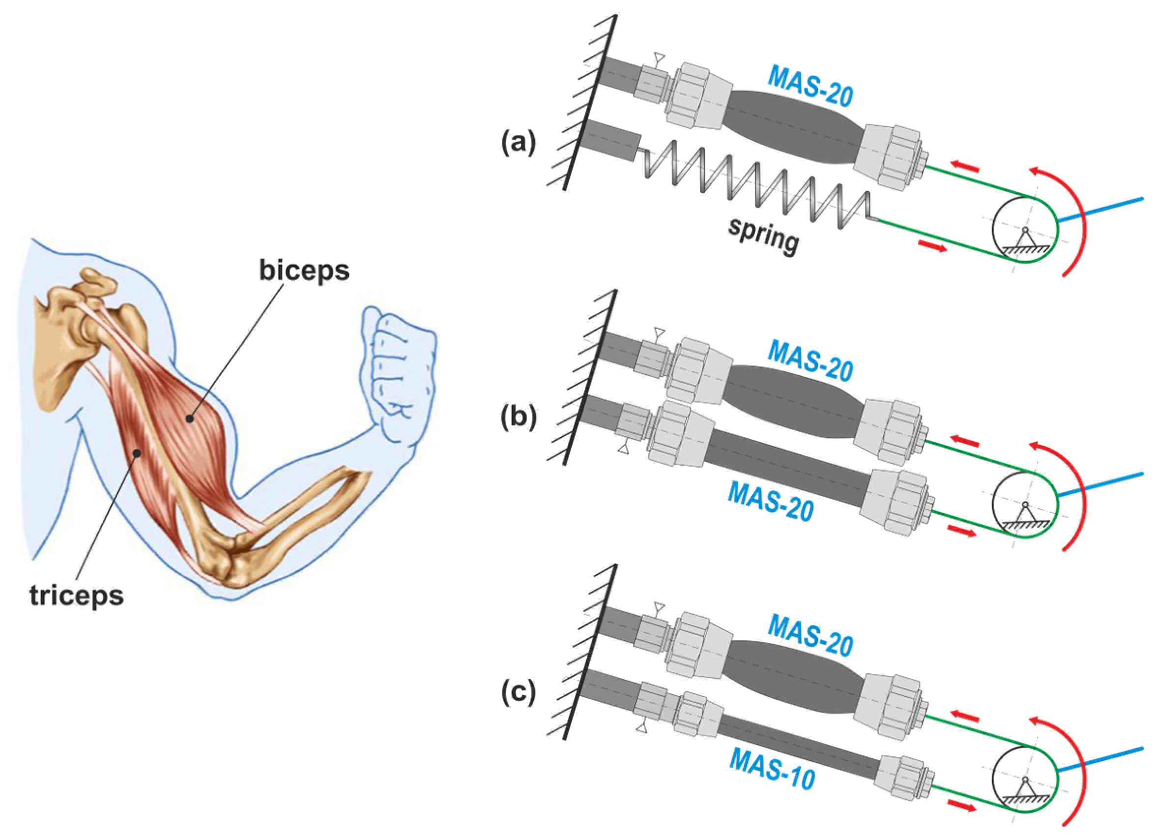
For the purpose of taking the measurements, a mechanism was designed similar to the muscular arrangement of the upper arm of a person. A pair of muscles is used to move the forearm in the elbow joint: the “tractor” biceps and “equalizer” triceps. The bigger of the two is the biceps.
A mechanism that uses muscle actuators-PAM is shown in Figure 1. The arrangement of the mechanism can be realized through one PAM and an equalizing spring (Figure 1a) or through a pair of oppositely arranged PAMs. It is possible to use a pair of identical PAMs (of the same size), Figure 1b, or a pair of PAMs that do not have the same force effects, Figure 1c.
Since the applied PAMs on the shoulder in the joint act in opposition, it is obvious that the force-dominant muscle creates a pulling force, which is counteracted by the force from the attached load, while the other muscle is only “auxiliary” in performing the backward movement.
For the implementation of the experiment, the model according to Figure 1c. This was incorporated into the construction of the measuring stand, which we will describe later.
Experiment preparation-measuring stand
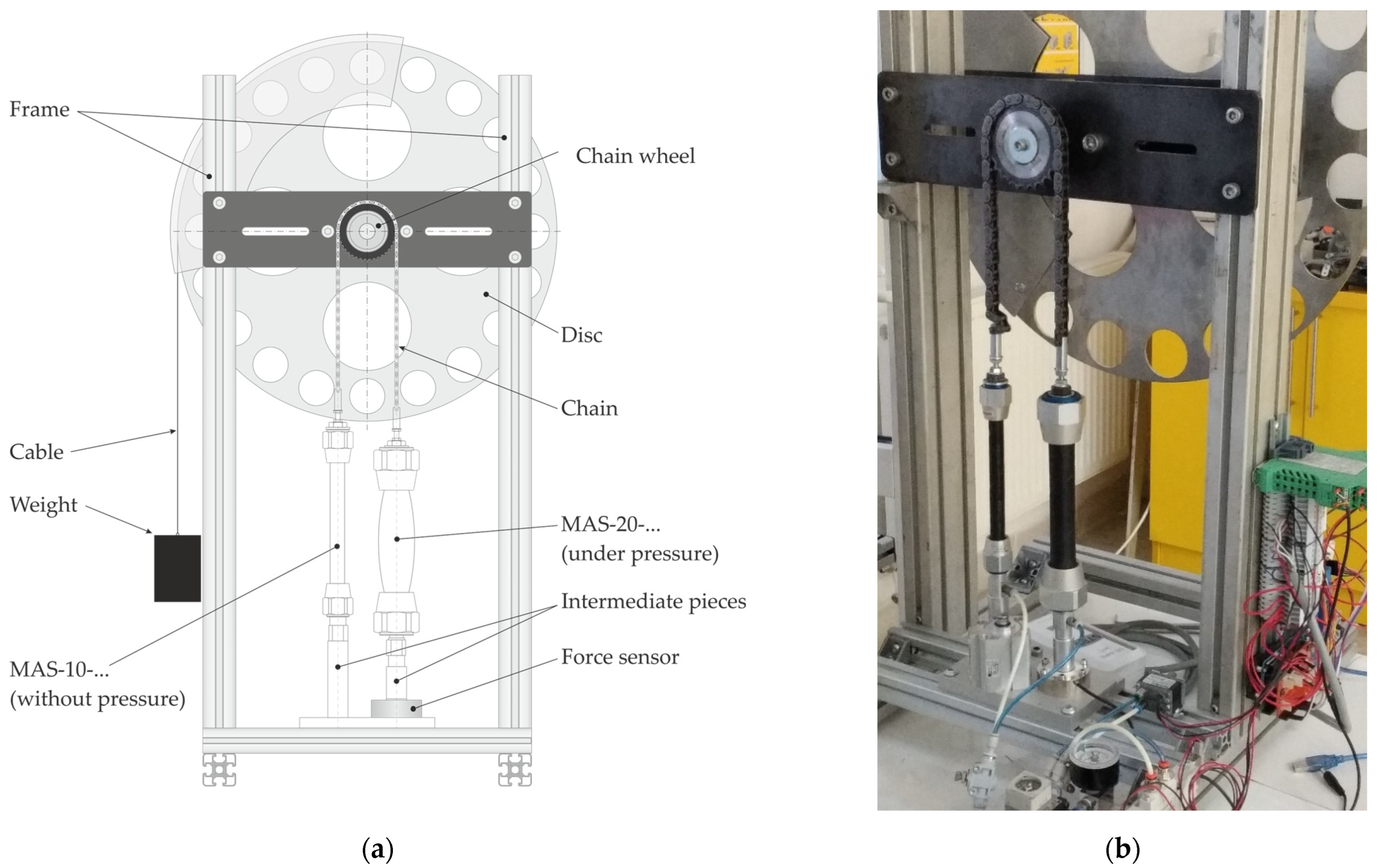
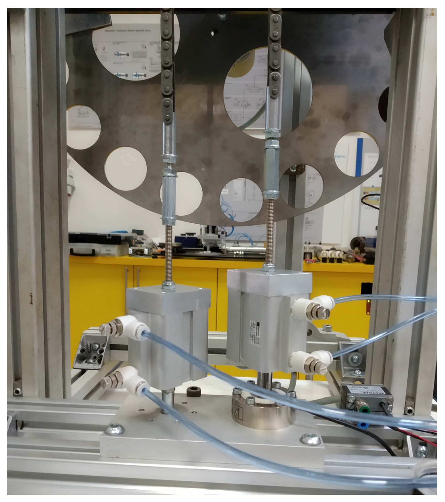
The implementation of the experiment assumed the design and implementation of a suitable measuring stand, as shown in Figure 2.
As the goal of the experiment, we chose to find the existing dependencies between the PAM-generated force, its reaction properties (contraction speed), and the level of its contraction at three levels of set working pressure while gradually increasing the load acting on the system.
When choosing pressures, we had to take into account the fact that the mechanism is made up of a pair of PAMs whose technical parameters stated by the manufacturer are not identical.
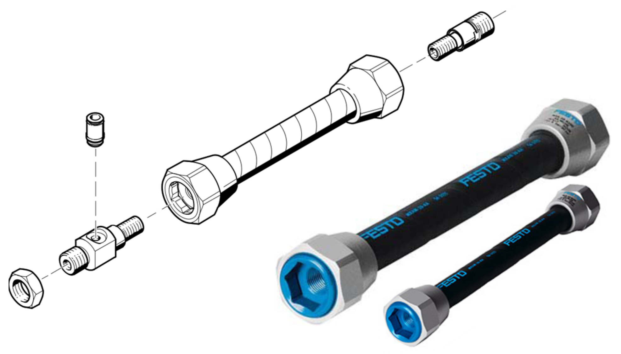
PAMs from the FESTO with the type designations MAS-10-N-120-AA-MCFK and MAS-20-N-120-A-MCGK, shown in Figure 3, were selected as mechanism drives for the purposes of measurements.
The technical parameters of the selected PAM are listed in Table 1.
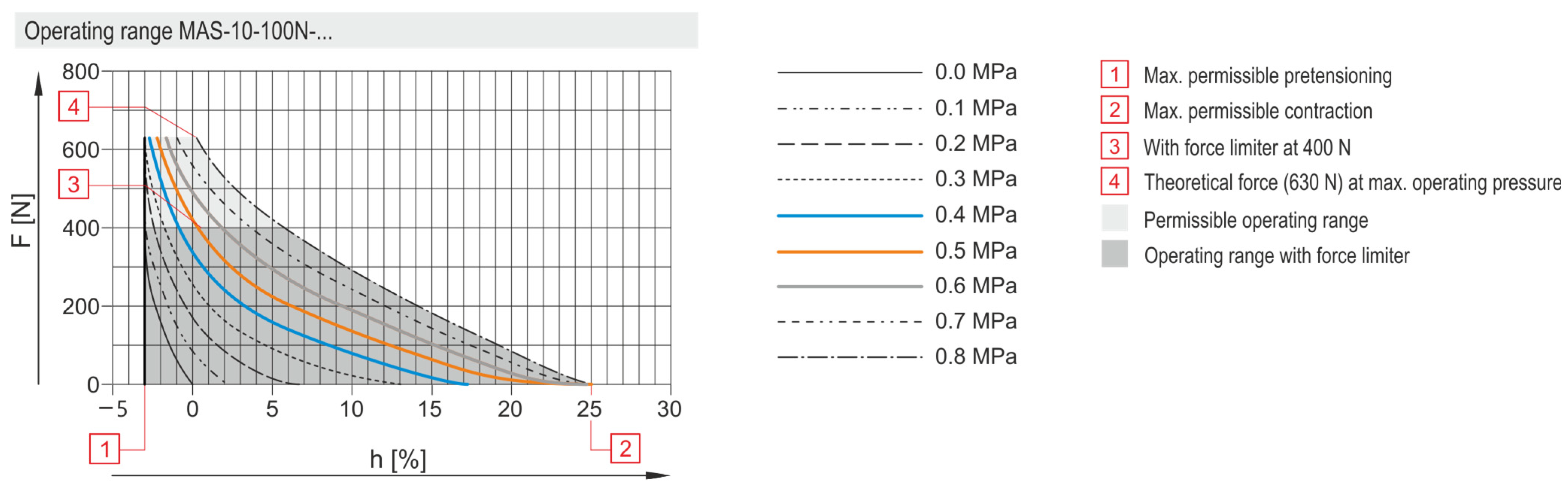
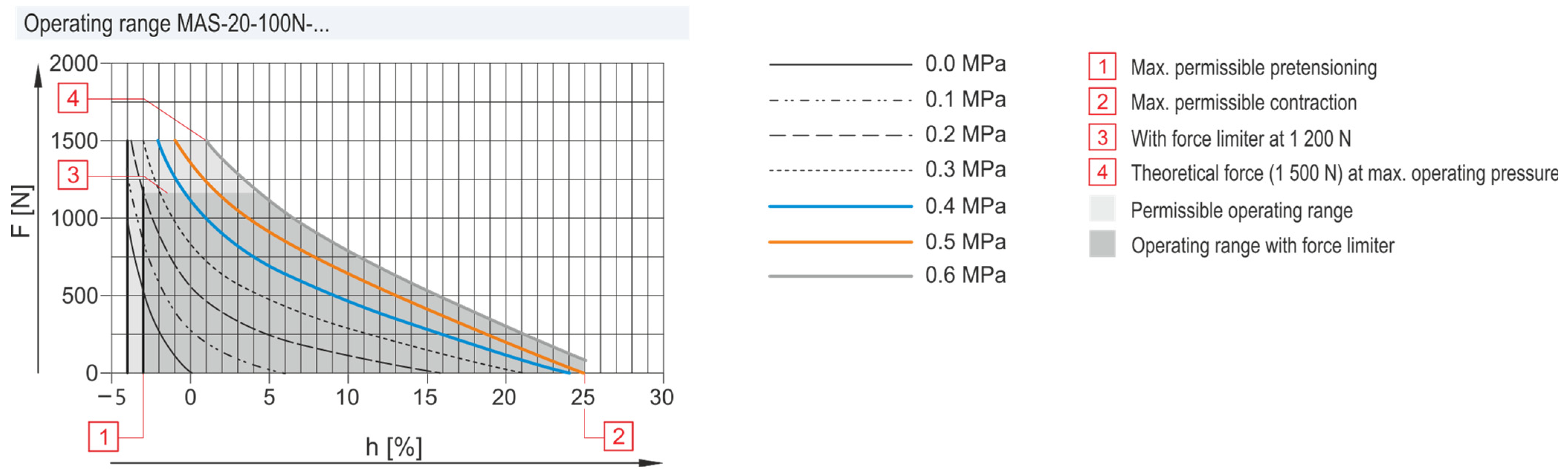
The curves of the dependence of force and contraction on pressure in PAM (as reported by the manufacturer) are shown in Figure 4 and Figure 5.
Due to the limitations of the parameters mentioned above, we chose pressures in the range of 0.4 MPa, 0.5 MPa, and 0.6 MPa. We considered this range of pressures to be sufficient, despite the fact that the PAM with the designation MAS-10-120N-… allows the use of a pressure of up to 0.8 MPa.
When choosing counterweight values for systems in the form of weights, we chose a scale from 1 kg to 11 kg, with increments of 1 kg, so as not to create an excessive stretch value (without pressure) in any of the PAM pairs. As shown by the curves reported by the PAM manufacturer, in both cases of PAM used, the maximum muscle pretension is allowed to be 3%.
In the mechanism, the main (measured) force is generated by the MAS-20-…, while the position adjustment is provided by the MAS-10-… (Figure 2a).
Both used PAMs are in the version with power supply from one side, while for reasons of height adjustment of the measured and balancing muscles, it was necessary to make special attachment modules. The differences in height result from the construction (dimensions of the flanges) of the muscles of different sizes and also from the need to place the load cell in the lower part of the measured muscle.
The forces developed by PAM were measured with a strain gauge (EMSYST EMS70-1 kN, Figure 2a) with the EMSYST ENS170 amplifier and entered through the AD 01 channel (see measurement diagram, below) to the microcontroller.
We measured the shortening of the muscle when filled with the appropriate pressure based on the recalculation of the rotation angle of the disk, which mediated the arm for placing the counterweight. The angle of this rotation was measured by an incremental rotation sensor of the brand HEIDENHAIN ROD 426 with a number of 1250 increments per revolution.
2.2. Description of Mechanism Operation Control
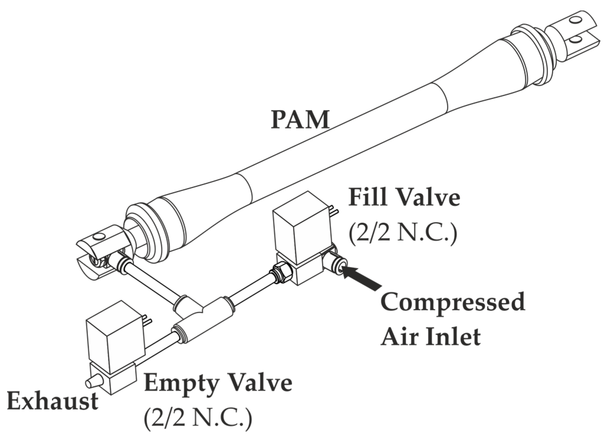
Controlling the activity of the PAM pair was carried out by the so-called “single” method, when the only inlet channel is provided for both filling and venting of each PAM. This method is mostly implemented by connecting a pair of 2/2 electropneumatic valves in a parallel arrangement to the PAM inlet channel. One of the valves ensures filling, the other vents PAM (Figure 6).
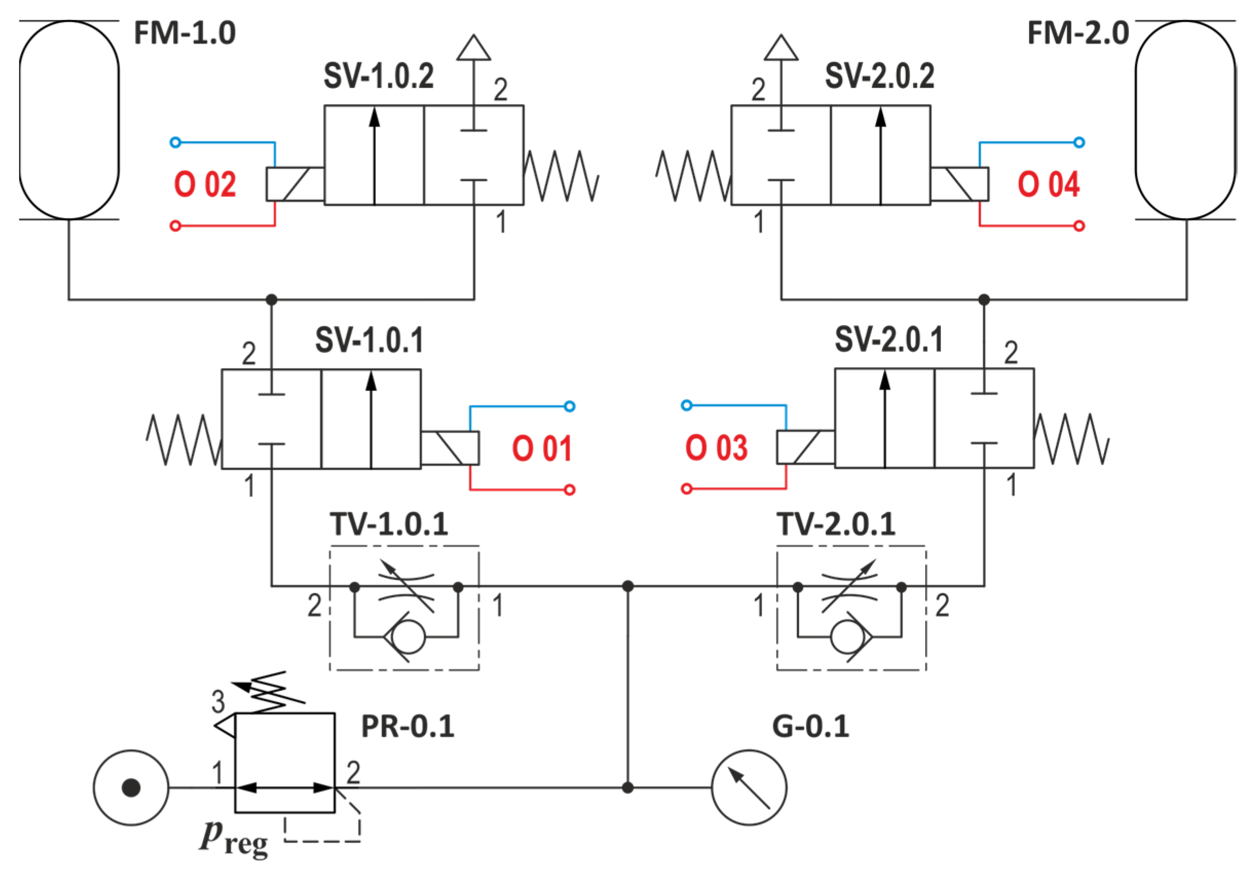
The pneumatic diagram of such a connection for a pair of PAMs is shown in Figure 7.
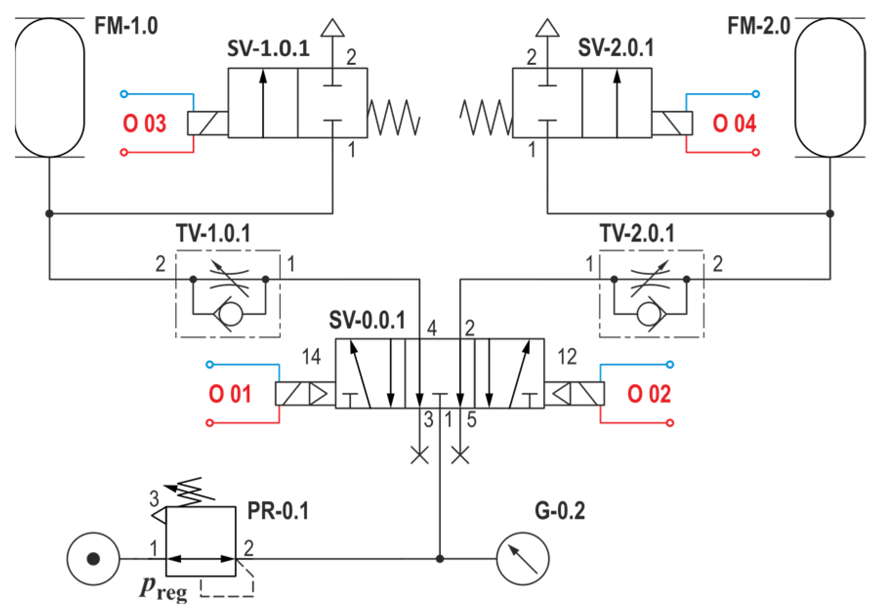
To control the PAM pair in the mechanism for our experiment, we chose a modified PAM connection method using a modified 5/3 electropneumatic valve, Figure 8—SV-0.0.1.
Modification of the 5/3 electropneumatic valve with vented central position consists of blending (closing) the venting channels 3 and 5 of the valve, which gives us the equivalent of a pair of 2/2 valves from Figure 7.
Before the start of the measurement cycle, the mechanism is in a state where FM-1.0 in the direction of channels 1–4 of the SV-0.0.1 valve is filled with compressed air, while FM-2.0 in the direction of channels 1–2 of the SV-2.0.1 valve is simultaneously vented. The contraction of the “weaker” of the PAM pair (MAS-10-…) and the simultaneous release of the “stronger” (MAS-20-…) occur.
At the start of the measurement cycle, filling of FM-2.0 and venting of FM-1.0 occur. During the measurement, the filling and venting of FM-1.0 and FM-2.0 are alternated once again.
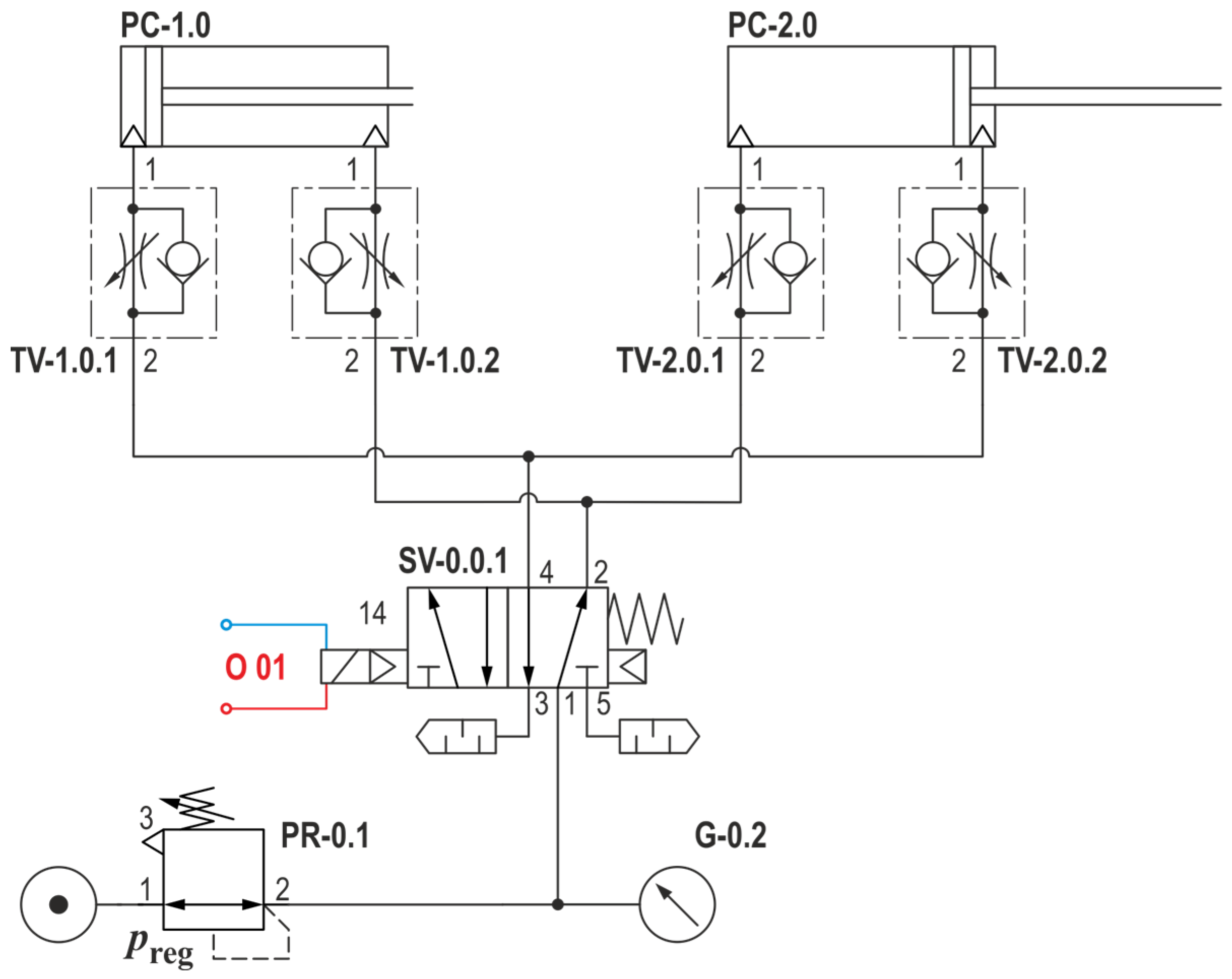
A mono-stable 5/2 electropneumatic valve was used to control double-acting pneumatic drives PC-1.0 and PC-2.0. The pneumatic diagram of such a connection between a pair of linear drives is shown in Figure 9.
The measurement cycle begins with the PC-1.0 drive rod in the “inserted” position and the PC-2 drive rod in the “extended” position. This arrangement replicates the situation before the start of the measurement cycle described in PAM. The chosen arrangement ensures the same distribution of the acting forces. We were forced to approach such an arrangement of the circuit due to the fact that both drives “act forcefully” during the “insertion” of the piston rod.
2.3. Simulation Study
As the PAM stretches due to the increase in pressure, the diameter of the combined sleeve and tube assembly changes in the radial direction, and the muscle shortens in the axial direction. The basic geometric characteristics of the PAM are defined as: l is the length of the tube, r is the radius of the tube, and φ0 is the braid angle, which is the angle between the helical fiber element and the axis of the tube. The axial force F can be described in Equation (1) as being linearly proportional to the relative pressure P [34].
For the individual parameters in the initialization dimensions, we can write from the geometric characteristics:
Reynolds et al. presented a phenomenological model for the dynamic behavior of PAM. In this paper, we used the dynamic PAM model published in [31]. Coefficients corresponding to three elements: nonlinear friction, spring, and contraction. In addition, the coefficient K(P) indicates the spring coefficient, and the coefficient C(P) indicates the damping coefficient and is dependent on whether the PMA is inflated or deflated. The equations describing the dynamics of the PAM system are:
In the given equations F(P) the axial force is provided. The nonlinearity of the PAM for the simulation model based on a simple geometric model of the muscle is given by the static characteristic of the drive, which was measured for the experiment. To obtain the coefficients C(P) and K(P), we implemented in the CAE environment PTC Creo Parametric 7.0 with a connection to PTC Matcad, where the simulation results were processed using built-in tools. On the basis of the performed simulation, the measured data were converted into a 4-order polynomial equation with R2 = 0.98 to 0.99. Equations (10)–(12) are the simulation results for MAS-20 and Equations (13)–(15) are the results for MAS-10.
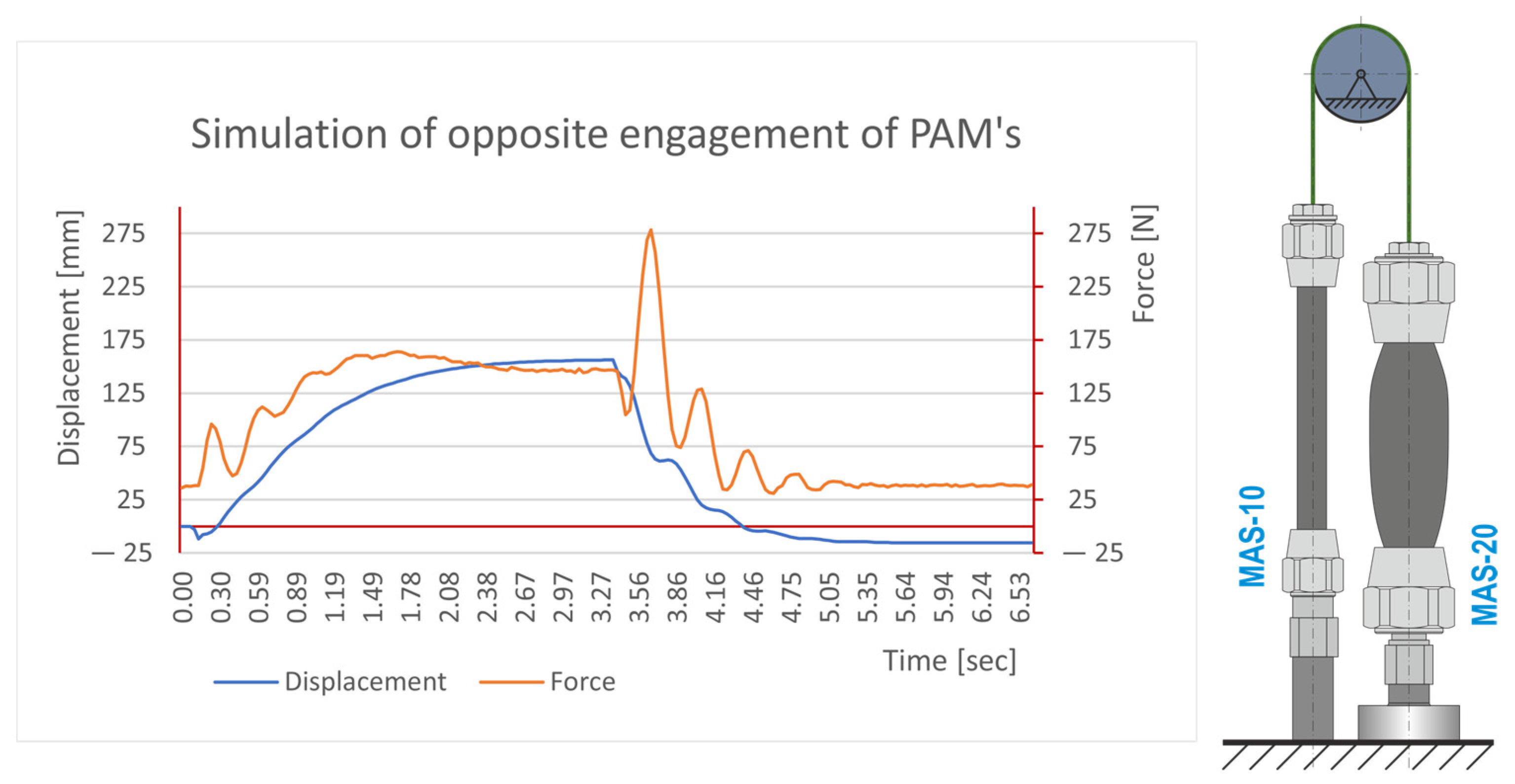
The simulation of one cycle using these parameters is shown in Figure 10.
2.4. Methodology of the Experiment
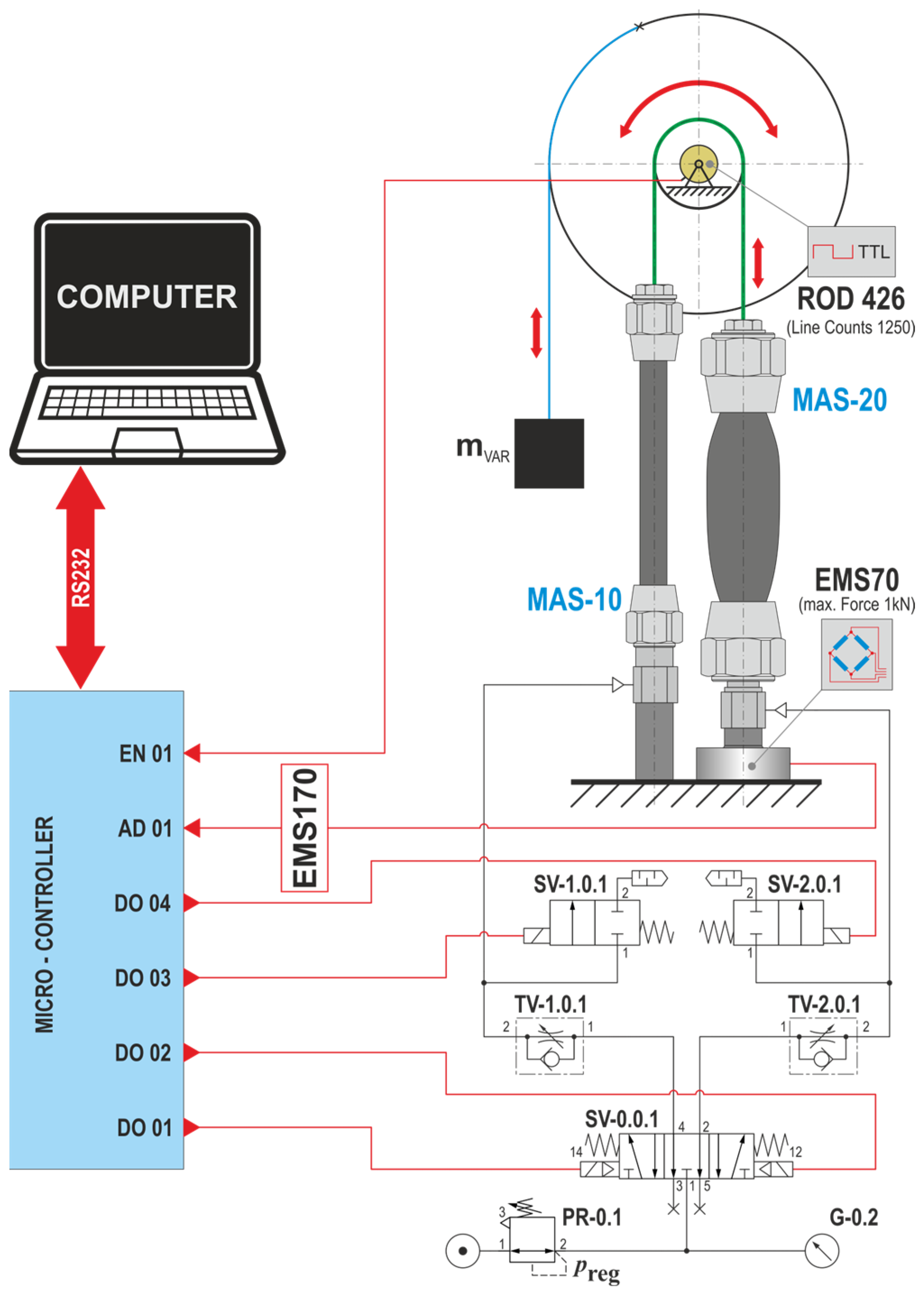
The measurement took place in an automated measuring loop controlled by the controller. The wiring diagram of the measuring chain for the implementation of the experiment is shown in Figure 11.
By initializing the mechanism for the experiment, both PAMs were brought to their basic positions (MAS-10-… pressurized, MAS-20-… without pressure).
The measurement cycle begins with the start of the measurement program, which, by setting the 5/3 valve SV-0.0.1 to position 12, starts the filling of the PAM marked MAS-20-… while at the same time the 2/2 valve marked SV-1.0.1 is activated in order to fill the PAM vents marked MAS-10-…
Subsequently, valve SV-0.0.1 is switched to position 14 with the simultaneous closing of valve SV-1.0.1 and opening of valve SV-2.0.1. This will start venting the PAM marked MAS-20-… and pressurizing the PAM marked MAS-10-…
The total cumulative time of filling and emptying the pair in each measurement cycle takes 6.5 s.
During one measurement cycle, at 30.518 Hz sampling, the change in rotation of the sprocket (or disc) is sensed as output from the connected incremental sensor, and the value of the contraction force is measured by the PAM.
An ATmega328 microcontroller with a clock rate of 16 MHz was used to control the valves. This microcontroller also provided communication with the sensors through external interrupts, which enabled controlled feedback.
The cycle implemented in this way was performed for each set pressure from the selected interval and each counterweight value used 10 times. With the chosen sampling of the rotation and force signals, the controller generated 200 values during one cycle, which were written to the disk of the connected PC via the RS232 interface, where they were processed into graphic outputs using the MS Excel spreadsheet.
The output of the measurement is the course of PAM forces and contractions over time and the reaction times of their contractions, from which it is possible to determine the speeds and accelerations of PAM contractions. By supplementing the graphic outputs of measuring pneumatic cylinders, we obtain a comparison of the characteristics of both systems (PAM vs. Mecman).
To illustrate the measured dependencies, we present selected graphs of the averaged data for the given measurement.
For comparison, a separate measurement was also performed on a modified stand, where REXROTH Mecman type 918 pneumatic linear actuators (bore 32 mm, stroke 15 mm) were used instead of PAM in a kinematically identically arranged system.
A modified measuring stand for comparative measurement on pneumatic cylinders is shown in Figure 12.
2.5. Description of Acting Forces and Displacements
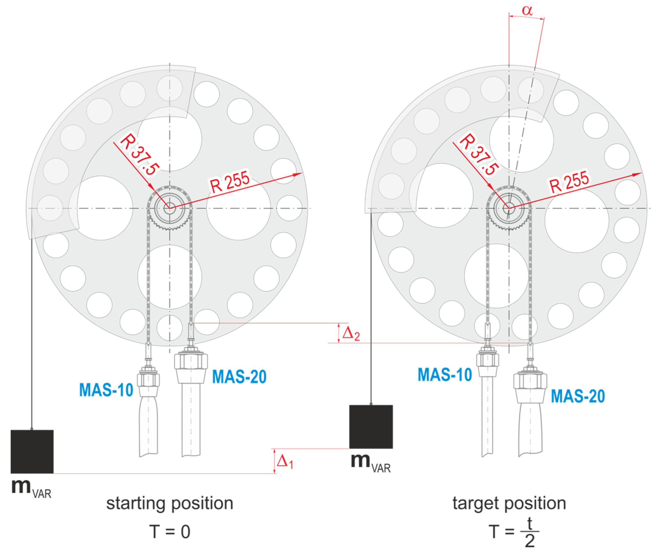
As mentioned above, the measuring mechanism consists of a pair of oppositely connected PAMs (MAS-10-… and MAS-20-…) connected by a chain through a toothed chain wheel with a diameter of 75 mm. The gear wheel is stored in a pair of rolling bearings (bearing houses FL204) on a common axis fixed on a disk with a diameter of 510 mm. The latter is used in the mechanism to simplify the calculations of the arms of the acting forces. There is a belted cable on the disc that carries a load of mVAR (in the range of 1 kg to 11 kg, i.e., 9.81 N to 107.87 N). The force generated by the PAM marked MAS-20-… is measured by a strain gauge.
The force ratios on the mechanism before the start of the measurement cycle and during the cycle are shown in Figure 13.
Displacements caused by contraction PAM shows the displacements ∆2 and ∆1 which represent the displacement of the weight on the arm (Figure 14).
3. Results
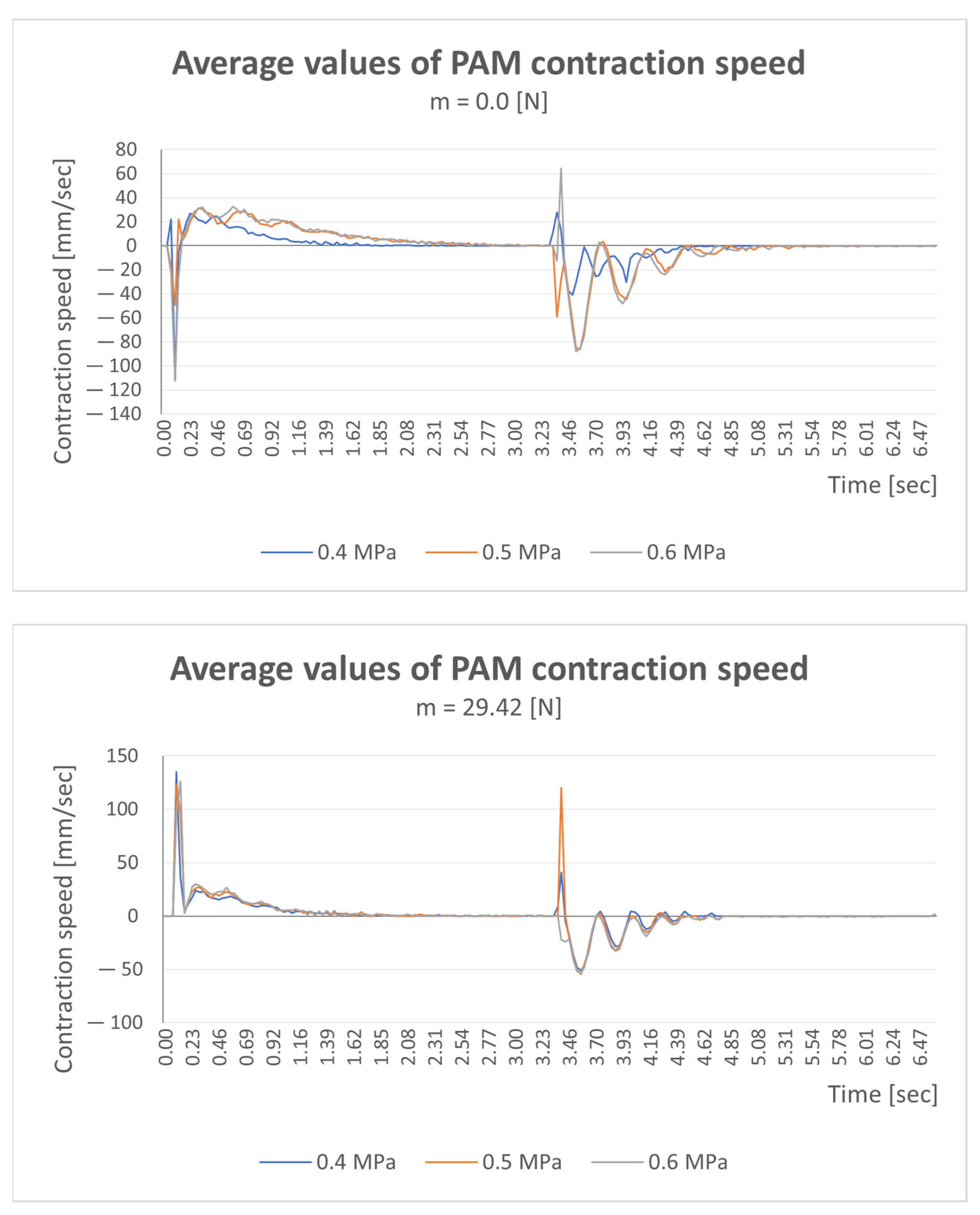
The measured values of individual measurements were processed into graphs. The average values of the measured data are always used for the mentioned dependencies of the measured quantities. Figure 15 shows the dependences necessary for comparison. We only present graphs of the averaged data for the given measurement.
Figure 15 presents graphs of the average PAM contraction speed for selected loads of 0 kg (0 N) and 3 kg (29.42 N). The displayed values were measured at three pressure values (0.4, 0.5, and 0.6 MPa). The obtained speed values reach the maximum value (+62 mm/s) for a load of 0 kg and maximum speed value (+132 mm/s) with a load of 3 kg.
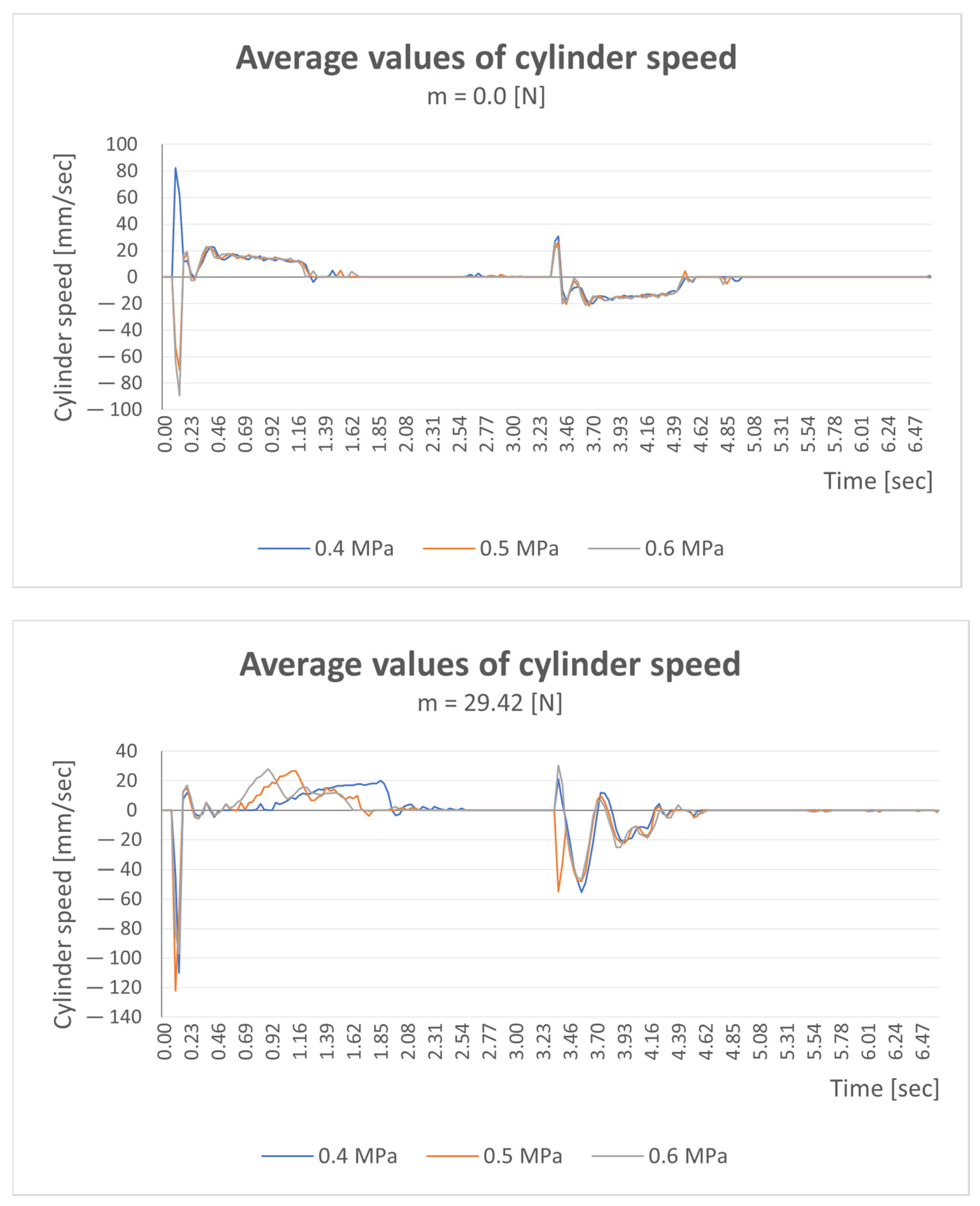
Figure 16 shows the average values of the displacement speeds of pneumatic cylinders without load (m = 0 N) and with a load of 3 kg (m = 29.42 N). The measured roller speed data increased from (80.5 mm/s) to maximum value (122.5 mm/s) under a load of 29.42 N.
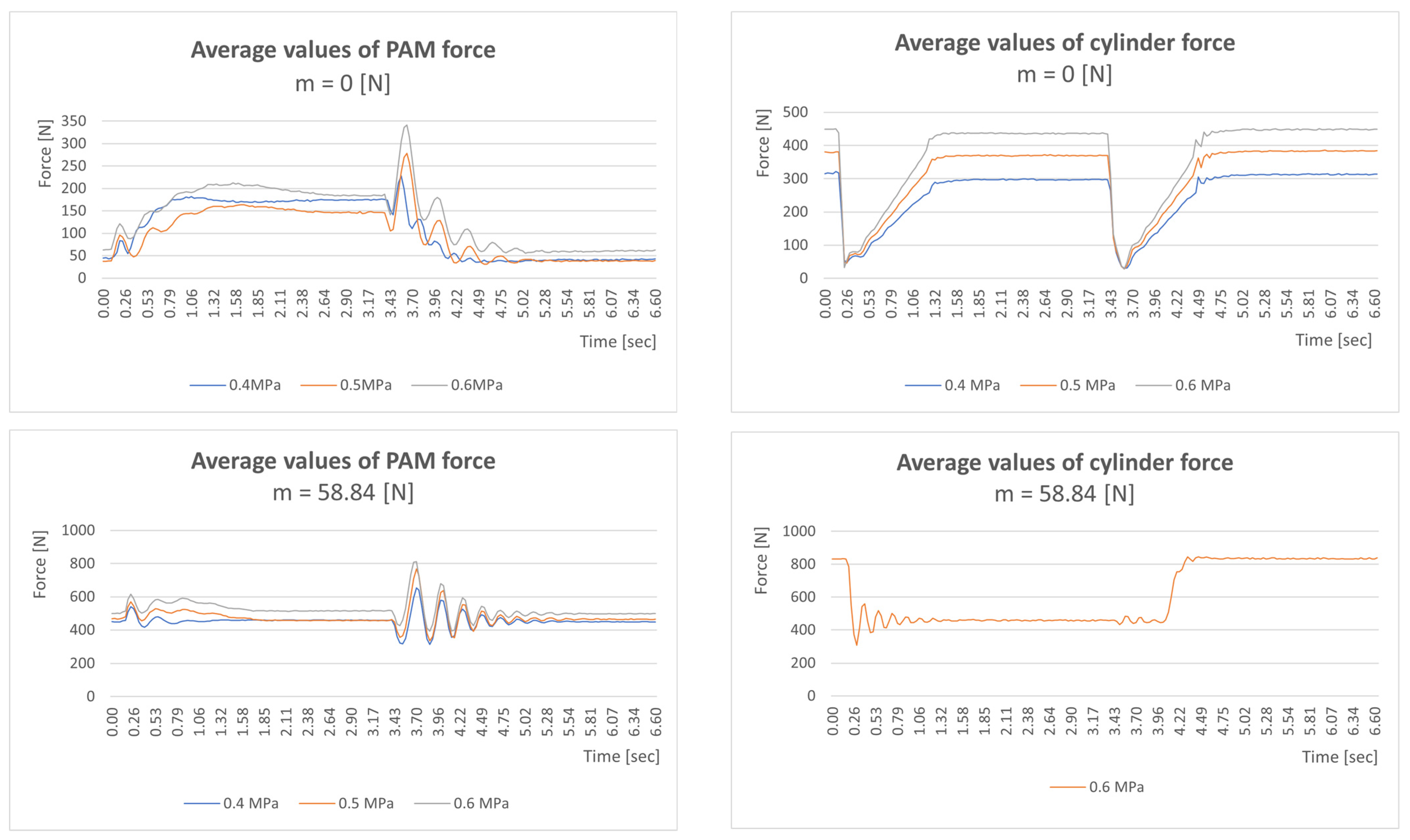
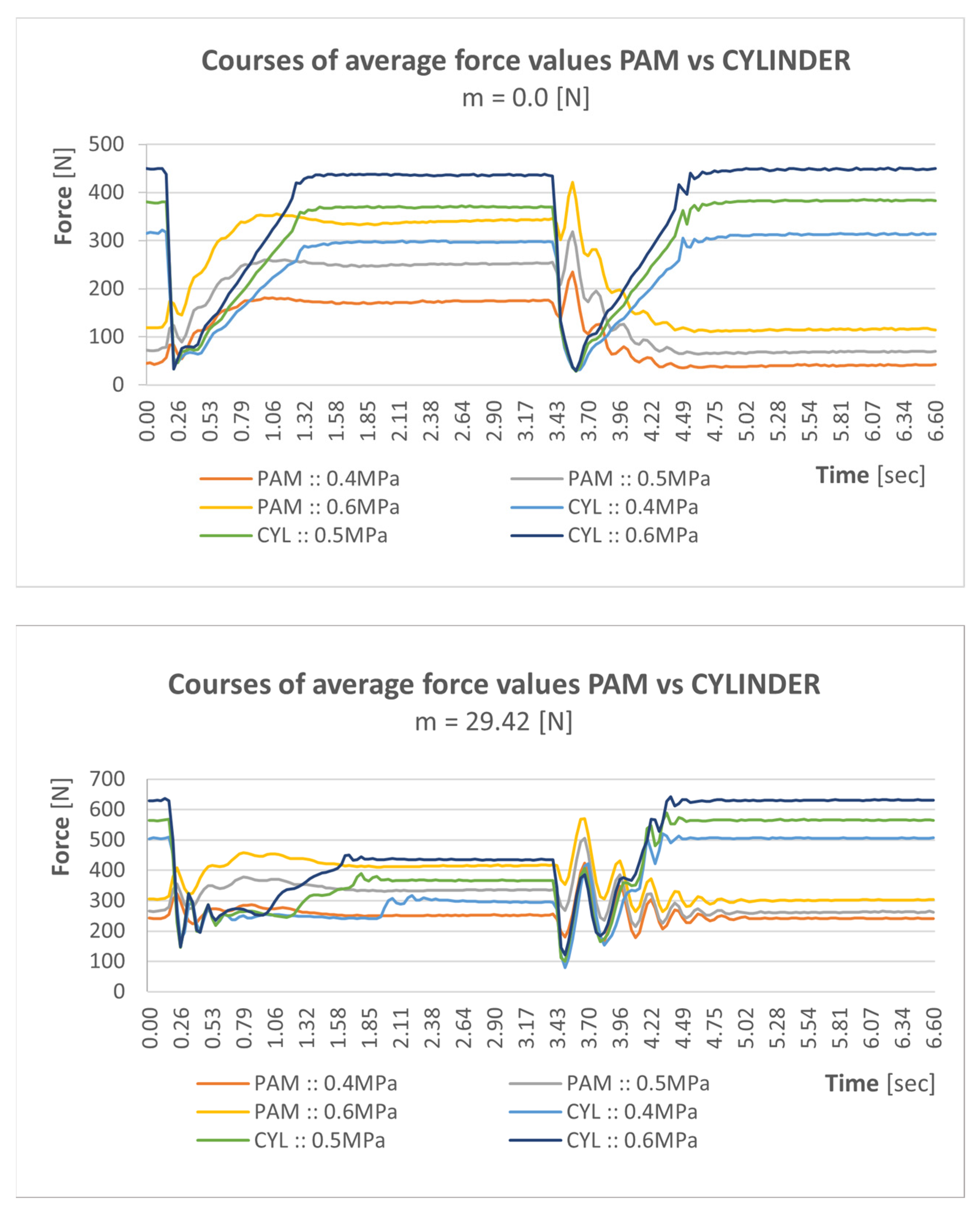
Figure 17 shows the average values of the course of force depending on time without load (m = 0 N) and with a load of 6 kg (m = 58.86 N). On the left side are graphs for PAM drives, and on the right side are REXROTH Mecman type 918 drives.
Measured data of the course of the force step for PAM drives with maximum values ranging from 345 N to 801 N with a load of 58.84 N.
Measured data of the course of the force step for Mecman drives type 918 with maximum values ranging from 452 N to 802 N with a load of 58.84 N.
4. Discussion
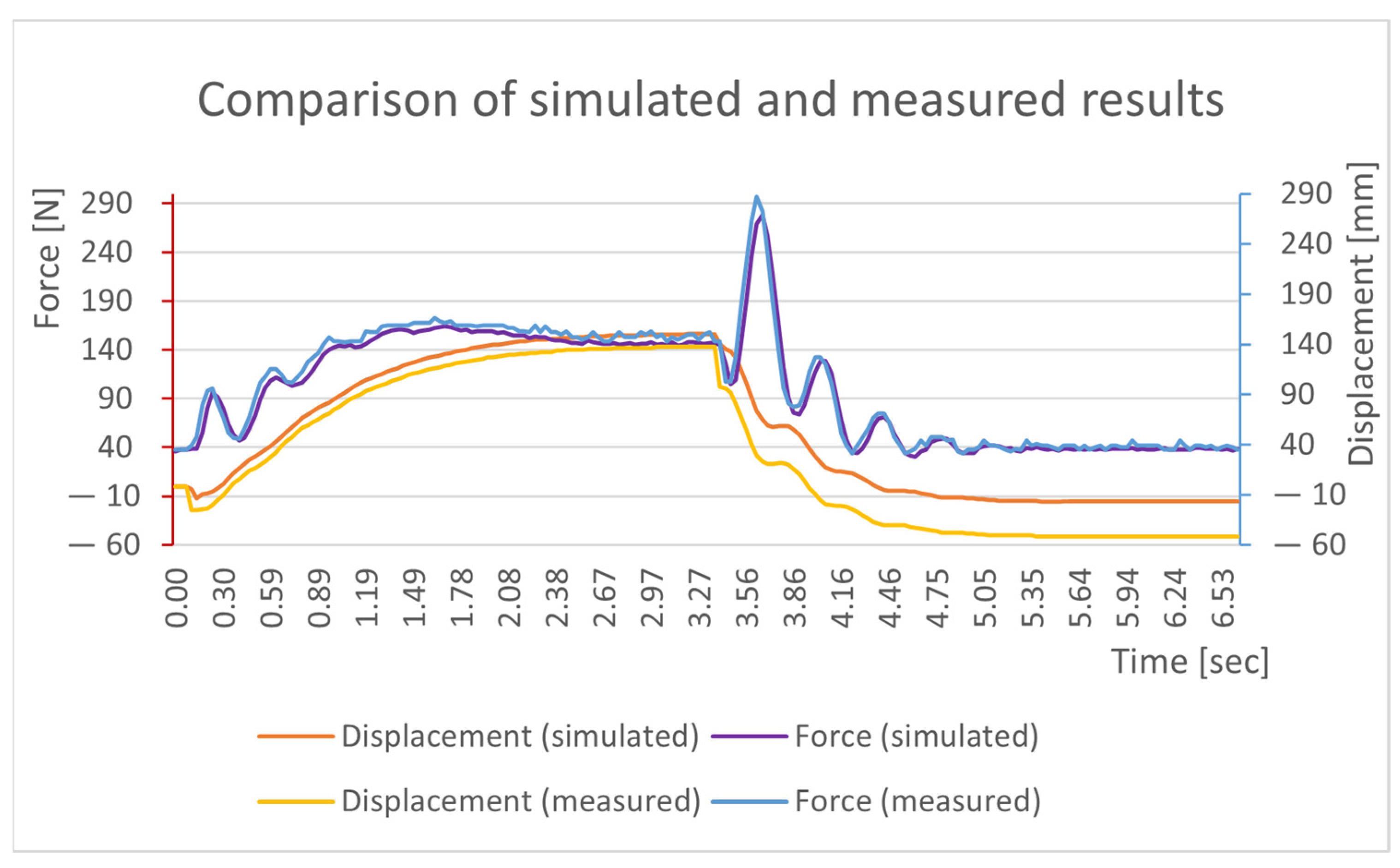
By comparing the simulation model and the measured data, which can be seen in Figure 18, it can be concluded that the obtained damping spring constants correspond to reality. The differences can be attributed to the different hose lengths and the reaction time of the indirectly operated pneumatic valve.
With the obtained constants listed in Equations (10)–(15), we will use them to create a simulation of a humanoid robot, which will allow us to optimize its design and determine the resulting parameters of individual moving joints. The disadvantage of the data obtained in this way is that the stated constants apply only to the tested pneumatic cylinders with the same elements in the pneumatic circuit. In the case of even minor changes (e.g., hose length, change of direct connection to an angle, change of material/diameter of used connecting hoses, etc.), there will be greater differences between simulation and reality.
Evaluation of superimposed graphs (forces, rotation), reaction speed at individual pressures, and comparison with cylinders.
The graphic courses of the measured values of the contraction times of the PAM and the pneumatic linear drive point to the following facts:
- Due to its non-linearity, PAM provides a “softer” course of response to initiation compared to used pneumatic cylinders;
- The PAM shows a larger “swing” in the force time course during reversal;
- The start-up characteristic of the power effect is comparable to pneumatic drives, but during reversal it shows very significant fluctuations (which necessarily causes problems in controlling them to the required value).
It will evaluate the advantages and disadvantages of using PAM in biologically inspired mechanisms.
Based on the measured values and trends, it is possible to state the following findings:
- Compared to linear pneumatic actuators, PAMs show greater power effects with lower requirements for built-up volume;
- On the other hand, their contraction does not reach the possibilities of linear drives (average shortening values comparable to the strokes of pneumatic linear drives are possible only at the cost of using PAM with a very large nominal length);
- Nonlinearity during contraction causes a hysteresis phenomenon, which can cause difficulty in their control;
- The control itself is not complex (from the point of view of technical security), but it requires high robustness of the control elements used.
Other uses in rehabilitation, exoskeletons, etc.
Thanks to their properties, PAMs are predestined for applications in the field of rehabilitation “automata” (technical physiotherapists), as their behavior is copied from a biological pattern and represents properties similar to those that a person controls when performing rehabilitation tasks.
The same is true in the field of exoskeletons, as their behavior is similar to the behavior of the human model from the point of view of the course of forces and contractions, and thus they appear more “natural” compared to similar devices built on other (purely technical) principles.
Overall, however, it is possible to conclude that any devices using compressed air as an energy carrier have a significant handicap in storing a sufficient supply of compressed air, at least for mobile applications.
By directly comparing the PAM with the Mecman drives (Figure 19) it is possible to state that the PAM venting is delayed compared to the Mecman cylinder by approx. 0.2 s.
Furthermore, it is interesting to observe the progress during contraction, where PAM shows higher shock absorption due to its flexible construction. In our system, this represented up to 30% faster oscillation stabilization in favor of PAM.
When relaxing the model, it can be concluded that the oscillation of the PAM system was more pronounced due to the high inertia of the system. The ripple in the time from 4 s to 5 s represents only the damping of the rubber hose with low damping. In contrast, the Mecman pneumatic cylinder hit the end position of the chamber, resulting in rapid damping and high shocks.
From these conclusions, it can be concluded that for applications where smoother damping is needed, it is more appropriate to use PAM drives, and for applications where speed is a requirement, it is more appropriate to use classic pneumatic drives.
5. Conclusions
This contribution dealt with the issue of using pneumatic muscles (PAM) in an oppositional arrangement for the realization of a mechanism similar to the human arm. By applying different diameters and lengths of these artificial muscles, greater variability of the entire system was guaranteed, and we became closer to the human arm model.
The verification was carried out when the inlet pressure changed under three loads. Weights in the range of 1 to 3 kg were used as the main load, and this corresponded to a total load of 0 N to 29.42 N. The chosen values were chosen because of their use in rehabilitation activities, which are aimed at strengthening and regenerating muscles, especially those of the upper or lower limbs of a person. The knowledge obtained during the experiment confirmed that the use of PAM is suitable for physiotherapeutic procedures, as their properties are very similar to those of the muscles in the human body, especially in our proposed arrangement.
The object of investigation is also based on the future installation of PAM as a compensation unit with an anthropomorphic device, the application of which should be intended primarily for rehabilitation facilities. However, the use of this system has a wider scope due to the values achieved. By creating different variant solutions that include pneumatic muscles in our applied experiment, he predestines them for very diverse use in various sectors of healthcare, medicine, military applications, the automotive industry, or in the creation of various mechatronic systems. The sudden change in force and path characteristics of pneumatic drives can be eliminated by using PAM. Many of the advantages of artificial muscles result from the regulation of their own stiffness.
From the point of view of the course of force over time, it can be concluded that the behavior of PAM drives compared to classic pneumatic drives has more suitable characteristics in terms of action on human muscles. The measured value of the PAM drive moves with a larger increase in force only after more than 3 s have passed. In the case of the classic Mecman drive, the performance will increase in a shorter time, approx. 1.1 s. Such a rapid increase is suitable for the automation of various processes in industry, but it is not suitable for acting on the muscles of the human body due to the action of larger shocks.
The continuation of the research will consist of the realization of a rehabilitation aid built on the basis of artificial muscles, which are much more acceptable for performing movement with the upper limbs of a person. Based on the measurement performed, it is necessary to increase the stiffness of the PAM in relaxation with an external shock absorber, which will ensure flexibility and, at the same time, quick stabilization of the position.
Author Contributions
Conceptualization, J.S.; methodology, P.T.; software, M.S.; validation, R.J.; formal analysis, M.S.; data curation, P.M.; writing—review and editing, P.T.; visualization, J.S.; supervision, R.J. All authors have read and agreed to the published version of the manuscript.
Funding
This research was funded by project KEGA: 020TUKE-4/2022 Development and implementation of new approaches in teaching industrial and collaborative robotics.
Data Availability Statement
Not applicable.
Acknowledgments
Thank for project VEGA: 1/0215/23 Research and development of robotic workplaces equipped with industrial and collaborative robots.
Conflicts of Interest
The authors declare no conflict of interest.
References
- Smith, R.; Cucco, E.; Fairbairn, C. Robotic Development for the Nuclear Environment: Challenges and Strategy. Robotics 2020, 9, 94. [Google Scholar] [CrossRef]
- Rojas, R.A.; Wehrle, E.; Vidoni, R. A Multicriteria Motion Planning Approach for Combining Smoothness and Speed in Collaborative Assembly Systems. Appl. Sci. 2020, 10, 5086. [Google Scholar] [CrossRef]
- Atmoko, R.A.; Yang, D.; Adhitya, R.Y. Cloud Robotics Architecture and Challenges on Disaster Mangement. AIP Conf. Proc. 2020, 2278, 020033. [Google Scholar]
- Bai, S.; Christensen, S.; Islam, M.R.U. An upper-body exoskeleton with a novel shoulder mechanism for assistive applications. In Proceedings of the 2017 IEEE International Conference on Advanced Intelligent Mechatronics, Munich, Germany, 3–7 July 2017; pp. 1041–1046. [Google Scholar]
- Castro, M.N.; Rasmussen, J.; Andersen, M.S.; Bai, S. A compact 3-DOF shouder mechanism constructed with scissors linkages for exoskeleton applications. Mech. Mach. Theroy 2019, 132, 264–278. [Google Scholar] [CrossRef]
- Armotion. Available online: https://www.neurorehabdirectory.com/rehab-products/armotion/ (accessed on 3 February 2023).
- Nakaoka, S.; Nakazawa, A.; Kanehiro, F.; Ikeuchi, K. Learning from Observation Paradigm: Leg Task Models for Enabling a Biped Humanoid Robot to Imitate Human Dances. Int. J. Robot. Res. 2007, 26, 829–844. [Google Scholar] [CrossRef]
- Janos, R.; Sukop, M.; Semjon, J.; Tuleja, P.; Marcinko, P.; Kocan, M.; Grytsiv, M.; Vagas, M.; Mikova, L.; Kelemenova, T. Stability and Dynamic Walk Control of Humanoid Robot for Robot Soccer Player. Machines 2022, 10, 463. [Google Scholar] [CrossRef]
- Semjon, J.; Janos, R.; Sukop, M.; Tuleja, P.; Hajduk, M.; Jurus, O.; Marcinko, P.; Virgala, I.; Vagas, M. Verification of the UR5 Robot’s Properties after a Crash Caused by a Fall of a Transferred Load from a Crane. Int. J. Adv. Robot. Syst. 2020, 17, 1729881420904209. [Google Scholar] [CrossRef]
- Pneumatic Artificial Muscles. Available online: https://en.wikipedia.org/wiki/Pneumatic_artificial_muscles (accessed on 3 February 2023).
- Chou, C.-P.; Hannaford, B. Static and dynamic characteristics of McKibben pneumatic artificial muscles. In Proceedings of the 1994 IEEE International Conference on Robotics and Automation, San Diego, CA, USA, 8–13 May 1994; pp. 281–286. [Google Scholar]
- Caldwell, D.G.; Tsagarakis, N.; Medrano-Cerda, G.A. Bio-mimetic actuators: Polymeric Pseudo Muscular Actuators and pneumatic Muscle Actuators for biological emulation. Mechatronics 2000, 10, 499–530. [Google Scholar] [CrossRef]
- Schulte, H. The Characteristics of the McKibben artifical muscle. In The Application of External Power in Prosthetcis and Orthotics; National Academy of Sciences-National Research Council: Washington, DC, USA, 1961; pp. 94–115. [Google Scholar]
- Liu, J.; Zuo, S.; Wang, L.; Zhang, Y. Simulation Investigation of a Soft Hydraulic Artificial Muscle. In Proceedings of the 2021 International Conference on Mechanical Engineering, Intelligent Manufacturing and Automation Technology (MEMAT), Guilin, China, 15–17 January 2021; p. 012068. [Google Scholar]
- Matisková, D.; Čakurda, T.; Marasová, D.; Balara, A. Determination of the Function of the Course of the Static Property of PAMs as Actuators in Industrial Robotics. Appl. Sci. 2021, 11, 7288. [Google Scholar] [CrossRef]
- Ferraresi, C.; Muscolo, G.G.; De Benedictis, C.; Paterna, M.; Gisolo, S.M. Design and Modeling of a Novel Pneumatic Passive Upper Limb Exoskeleton Based on McKibben Artificial Muscle. 2021. Available online: https://webthesis.biblio.polito.it/19574/1/tesi.pdf (accessed on 3 February 2023).
- Trojanová, M.; Hošovský, A.; Čakurda, T. Evaluation of Machine Learning-Based Parsimonious Models for Static Modeling of Fluidic Muscles in Compliant Mechanisms. Mathematics 2023, 11, 149. [Google Scholar] [CrossRef]
- Trojanová, M.; Čakurda, T.; Hošovský, A.; Krenický, T. Estimation of Grey-Box Dynamic Model of 2-DOF Pneumatic Actuator Robotic Arm Using Gravity Tests. Appl. Sci. 2021, 11, 4490. [Google Scholar] [CrossRef]
- Mirvakili, S.M.; Sim, D.; Hunter, I.W.; Langer, R. Actuation of untethered pneumatic artificial muscles and soft robots using magnetically induced liquid-to-gas phase transitions. Sci. Robot. 2020, 5, eaaz4239. [Google Scholar] [CrossRef] [PubMed]
- Minh, T.V.; Tjahjowidodo, T.; Ramon, H.; Van Brussel, H. Control of a pneumatic artificial muscle (PAM) with model-based hysteresis compensation. In Proceedings of the IEEE/ASME International Conference on Advanced Intelligent Mechatronics, Singapore, 14–17 July 2009; pp. 1082–1087. [Google Scholar]
- Yeh, T.J.; Wu, M.-J.; Lu, T.-J.; Wu, F.-K.; Huang, C.-R. Control of McKibben pneumatic muscles for a power-assist, lower-limb orthosis. Mechatronics 2010, 20, 686–697. [Google Scholar] [CrossRef]
- Van Damme, M.; Beyl, P.; Vanderborght, B.; Van Ham, R.; Vanderniepen, I.; Versluys, R.; Daerden, F.; Lefeber, D. Modeling Hysteresis in Pleated Pneumatic Artificial Muscles. In Proceedings of the 2008 IEEE Conference on Robotics, Automation and Mechatronics, Chengdu, China, 21–24 September 2008; pp. 471–476. [Google Scholar]
- Zang, X.; Liu, Y.; Heng, S.; Lin, Z.; Zhao, J. Position control of a single pneumatic artificial muscle with hysteresis compensation based on modified Prandtl-Ishlinskii model. Biomed. Mater. Eng. 2017, 28, 131–140. [Google Scholar] [CrossRef]
- Xie, S.; Liu, H.; Wang, Y. A method for the length-pressure hysteresis modeling of pneumatic artificial muscles. Sci. China Technol. Sci. 2020, 63, 829–837. [Google Scholar] [CrossRef]
- Zhao, J.; Zhong, J.; Fan, J. Position Control of a Pneumatic Muscle Actuator Using RBF Neural Network Tuned PID Controller. Math. Probl. Eng. 2015, 2015, 810231. [Google Scholar] [CrossRef]
- Zhu, L.; Shi, X.; Chen, Z.; Zhang, H.; Xiong, C. Adaptive Servomechanism of Pneumatic Muscle Actuators with Uncertainties. IEEE Transac. Ind. Electron. 2017, 64, 3329–3337. [Google Scholar] [CrossRef]
- Schreiber, F.; Sklyarenko, Y.; Runge, G.; Schumacher, W. Model-based controller design for antagonistic pairs of fluidic muscles in manipulator motion control. In Proceedings of the IEEE 17th International Conference on Methods and Models in Automation and Robotics (MMAR), Miedzyzdrojie, Poland, 27–30 August 2012; pp. 499–504. [Google Scholar]
- Nowakowski, M.; Kurylo, J. Usability of Perception Sensors to Determine the Obstacles of Unmanned Ground Vehicles Operating in Off-Road Environments. Appl. Sci. 2023, 13, 4892. [Google Scholar] [CrossRef]
- Zhang, Z. Modeling, Analysis, and Experiments of Inter Fiber Yarn Compaction E_ects in Braided Composite Actuators. Ph.D. Thesis, Virginia Polytechnic Institute, Blacksburg, VA, USA, 2012. [Google Scholar]
- Kydoniefs, A.D. Finite Axisymmetric Deformations of An Initially Cylindrical Membrane Reinforced with Inextensible Cords. Q. J. Mech. Appl. Math. 1970, 23, 481–488. [Google Scholar] [CrossRef]
- Matsikoudi-Iliopoulou, M. Finite axisymmetric deformations with torsion of an initially cylindrical membrane reinforced with one family inextensible cords. Int. J. Eng. Sci. 1987, 25, 673–680. [Google Scholar] [CrossRef]
- Liu, W.; Rahn, C.R. Fiber-reinforced membrane models of McKibben actuators. Transac. ASME J. Appl. Mech. 2003, 70, 853–859. [Google Scholar] [CrossRef]
- Reynolds, D.; Repperger, D.; Phillips, C.; Bandry, G. Modeling the dynamic characteristics of pneumatic muscle. Ann. Biomed. Eng. 2003, 31, 310–317. [Google Scholar] [CrossRef] [PubMed]
- Ganguly, S.; Garg, A.; Pasricha, A.; Dwivedy, S.K. Control of pneumatic artificial muscle system through experimental modelling. Mechatronics 2012, 22, 1135–1147. [Google Scholar] [CrossRef]
Figure 1.
Analogues of the technical solution for the human arm (a) PAM with spring, (b) two PAM’s with the same parameters, (c) two PAM’s with different parameters.
Figure 1.
Analogues of the technical solution for the human arm (a) PAM with spring, (b) two PAM’s with the same parameters, (c) two PAM’s with different parameters.

Figure 2.
Measuring stand (a) model, (b) photo.

Figure 3.
PAM (FESTO).

Figure 4.
Characteristics of MAS-10-N-120-A-MCFK.

Figure 5.
Characteristics of MAS-20-N-120-A-MCGK.

Figure 6.
Control of a “single” connected PAM.

Figure 7.
Wiring diagram of a “single” controlled PAM pair.

Figure 8.
Wiring diagram of a pair of “single” controlled PAMs using 2/2 and 5/3 valves.

Figure 9.
Connection diagram of a pair of pneumatic cylinders.

Figure 10.
Simulation graph simulated in pressure 5 bar.

Figure 11.
Schematic of the measuring chain.

Figure 12.
Measuring mechanism adapted for pneumatic cylinders.

Figure 13.
Distribution of forces during PAM activity.

Figure 14.
Displacements induced by PAM activity.

Figure 15.
Measured average values of PAM contraction speed.

Figure 16.
Average values of the displacement speed of pneumatic cylinders.

Figure 17.
Average values of the force curve as a function of time.

Figure 18.
Comparison of the simulation model with the measured data of the drives.

Figure 19.
Average values of the force value PAM versus Mecman.


Table 1.
PAM parameters.
| MAS-10-N-120-A-MCFK | MAS-20-N-120-A-MCGK | |
|---|---|---|
| Size | 10 | 20 |
| Nominal lenght | 120 mm | 120 mm |
| Operating pressure | max. 0.8 MPa | max. 0.6 Mpa |
| Teoretical force | 630 N | 1500 N |
| Force limiter | 400 N | 1200 N |
Disclaimer/Publisher’s Note: The statements, opinions and data contained in all publications are solely those of the individual author(s) and contributor(s) and not of MDPI and/or the editor(s). MDPI and/or the editor(s) disclaim responsibility for any injury to people or property resulting from any ideas, methods, instructions or products referred to in the content. |
© 2023 by the authors. Licensee MDPI, Basel, Switzerland. This article is an open access article distributed under the terms and conditions of the Creative Commons Attribution (CC BY) license (https://creativecommons.org/licenses/by/4.0/).
Share and Cite
MDPI and ACS Style
Tuleja, P.; Jánoš, R.; Semjon, J.; Sukop, M.; Marcinko, P. Analysis of the Antagonistic Arrangement of Pneumatic Muscles Inspired by a Biological Model of the Human Arm. Actuators 2023, 12, 204. https://doi.org/10.3390/act12050204
AMA Style
Tuleja P, Jánoš R, Semjon J, Sukop M, Marcinko P. Analysis of the Antagonistic Arrangement of Pneumatic Muscles Inspired by a Biological Model of the Human Arm. Actuators. 2023; 12(5):204. https://doi.org/10.3390/act12050204
Chicago/Turabian StyleTuleja, Peter, Rudolf Jánoš, Ján Semjon, Marek Sukop, and Peter Marcinko. 2023. "Analysis of the Antagonistic Arrangement of Pneumatic Muscles Inspired by a Biological Model of the Human Arm" Actuators 12, no. 5: 204. https://doi.org/10.3390/act12050204
Note that from the first issue of 2016, this journal uses article numbers instead of page numbers. See further details here.