Article

A Modular Soft Gripper with Combined Pneu-Net Actuators

1
College of Mechanical and Electrical Engineering, Hohai University, Changzhou 213022, China
2
School of Mechanical Engineering, Southeast University, Nanjing 211189, China
3
Department of Mechanical Engineering, York University, Toronto, ON M3J 1P3, Canada
*
Author to whom correspondence should be addressed.
Actuators 2023, 12(4), 172; https://doi.org/10.3390/act12040172
Submission received: 13 March 2023 / Revised: 30 March 2023 / Accepted: 8 April 2023 / Published: 13 April 2023
(This article belongs to the Section Actuators for Robotics)

Abstract

:
Soft Pneumatic-Network (Pneu-Net) Actuators (SPAs) have been used extensively in making soft grippers, due to their simple driving forms and large bending deformation. However, the capabilities of the regular SPAs in complex soft gripping application environments are alone insufficient. This work, thus, proposes a modular soft gripper that combines the functionalities of regular and herringbone actuators. The bending deformation characteristics of the two actuators under pneumatic pressures are verified by finite element (FE) simulations and experiments. The functional characteristics of the two actuators are investigated experimentally through a series of methods including the blocking force test, lifting test, grasping strength test, and suction force test. The experimental results show that the regular actuator has the advantages of greater longitudinal bending deformation and higher blocking force; while, the herringbone actuator has better lifting stability and grasping strength due to its conformal deformations both in longitudinal and transverse directions. In addition, the vacuum experiments demonstrate that the actuators can lift heavy plate-like objects through vacuum suction. Based on the functional behaviors of the two actuators, the proposed modular gripper is loaded onto automatic equipment, and the gripper is tested to hook, grasp, or lift various objects with different shapes, sizes, and weights. In essence, the modular and multi-functional characteristics of the design make it a promising candidate for relatively complex and advanced gripping applications.

1. Introduction

In recent years, soft grippers have attracted a lot of interest in the field of soft robotics, thanks to advances in material science. In comparison to rigid mechanical grippers, soft grippers are made of soft, compliant materials; which, allow them to interact more flexibly and safely with objects [1]. Examples of such materials include elastomer [2,3], shape–memory alloy [4], electromagnetic polymer [5], granular material [6], low melting point alloy [7], etc. Soft grippers based on fluidic elastomer actuators (FEAs) are typically made of elastomers and are driven by pressurized fluids (gases or liquids); while, the fluid flow path and chamber structure can be designed to achieve different bending features. Simple fluid flow paths and chamber structures, however, may be insufficient, particularly in applications requiring relatively high grip strength or stability [8,9,10]. Generally, these problems could be addressed with the integration of multiple FEAs in others to provide sufficient gripper–object interactions [11,12,13]. This, however, increases material usage and overall system complexity.
Various FEAs structures have been reported in past studies, including fiber-reinforced structure [14], artificial muscle [15], Pneumatic-Network (Pneu-Net) [16], etc. Amongst the FEAs, the Pneu-Net stands out with its simple structure, fast response, and large deformation features [17,18,19]. Soft Pneu-Net Actuators (SPAs), comprising a series of chambers in an elastomer, can be made to have different types of performance, such as extension/contraction, bending, twisting/helical motion, bidirectional/omnidirectional motion, etc. [20,21,22]. Based on the specific motion, SPAs have found applications in rehabilitation [23], food handling [24], biomimetics [25,26], soft gripping [27,28], etc. However, many SPAs-based grippers fall short of maximizing the actuator’s grasping potential as indicated by the necessity of applying excessively high pressure to particular objects to grasp them [11], and/or the need to use multiple actuators to increase grip stability [12]. Moreover, as objects often come in various shapes and weights, a soft gripper with only one actuator design may not be efficient in certain grasping scenarios (such as when grasping larger objects than the gripper); which, is why a modular soft gripper combining multiple functionalities is crucial.
In this work, we propose a modular soft gripper that is composed of two types of soft Pneu-Net Actuators (i.e., a regular actuator and a herringbone actuator). Under pneumatic pressures, the regular actuator can bend only in the longitudinal direction; whereas, the herringbone actuator can bend in both the longitudinal and transverse directions, as reported in our previous work [16]. In the study, the influences of the chamber inclination angle of the herringbone actuator on the bending performance, blocked force, and grip strength were investigated in depth. In order to harness the strengths of both the regular actuator and herringbone actuator, we combined both designs in the gripping system reported in this work for grasping different objects with complex shapes. The system also incorporates suction cups, which aid object lifting by vacuum suction. We carried out Finite Element (FE) simulations to characterize the bending performance of the soft actuators, coupled with a series of experiments to investigate the deformation and force behaviors of the gripping system. Finally, an automation platform was developed to demonstrate the applicability of the soft gripper grasping and lifting applications.

2. Materials and Methods

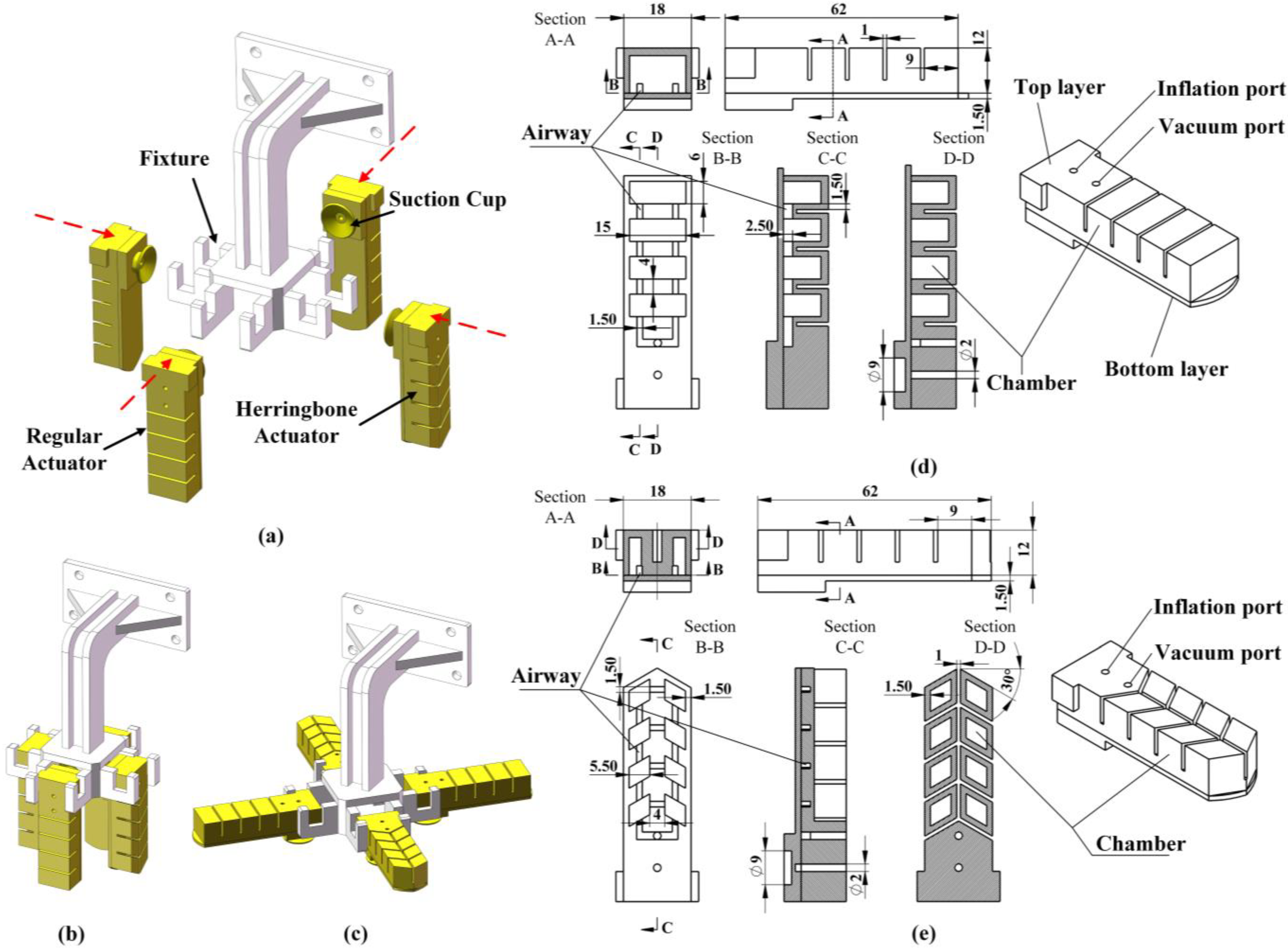
2.1. Modular Gripper Design

The modular soft gripper is made up of two regular actuators and two herringbone actuators assembled on a fixture, with four suction cups assembled on the bottom of the actuators (Figure 1a). Two groups of identical actuators are assembled in opposing vertical positions to achieve the grasping function (Figure 1b). When the gripper is employed for suction function, as shown in Figure 1, the vertical actuators are manually turned to be horizontal (Figure 1c). Schematics of the regular and the herringbone actuators are shown in Figure 1d,e. Both actuators have an active top layer (which consists of a series of elastic chambers connected by a network of air channels) and a passive bottom layer (which limits the extension of the active part). A detailed view of the top layer can be seen in the B-B and D-D sections. In the regular actuator (Figure 1d), four parallel rectangular chambers connect two “longitudinal channels”, while eight parallelogrammatic chambers are connected by a “transverse passage” and a “longitudinal passage” in the herringbone actuator (Figure 1e), respectively. In addition, an inflating port is vertically connected to the Pneu-Net chambers and a vacuum port is installed through the suction cup, respectively. For fairness of comparison, the two actuators were designed with the same outline dimensions. The total volumes of the actuator were therefore nearly the same. The chamber inclination angle of the herringbone actuator was designed into 30° based on our previous study [16].

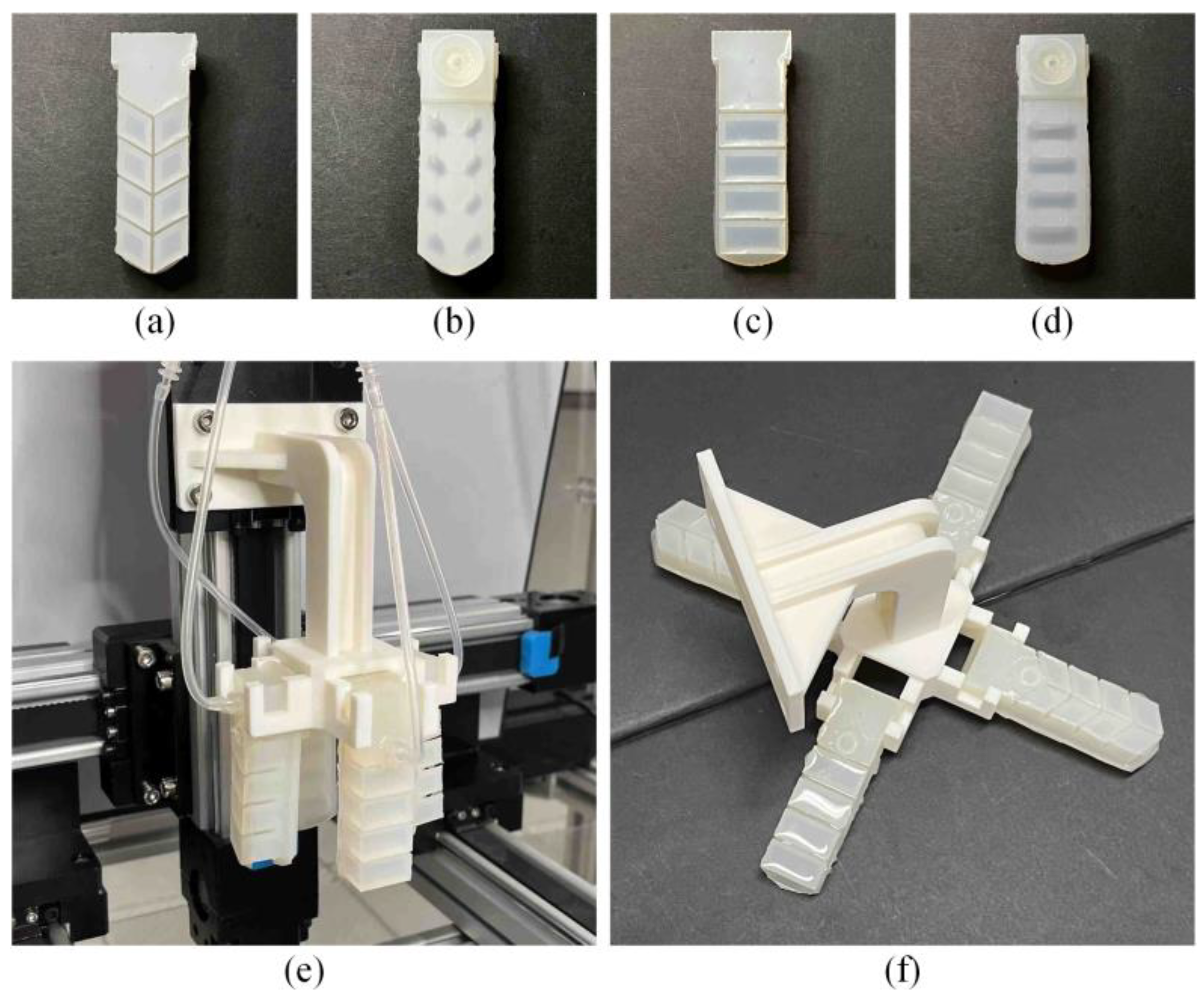
2.2. Soft Actuator Fabrication

The fabrication process follows the traditional casting method [29,30], as illustrated in Figure S1. Three 3D-printed molds were employed, two of which were integrated for the top layer and one for the bottom layer. After mixing and degassing, the polymer Dragon skin 30 (Part A and B) (DS30, Smooth-On Incorporation, Macungie, PA, USA), is poured into the mold. After polymerization at room temperature (15 h), the top and bottom layers are bonded using the polymer solution and baked all together at 80 °C for 30 min. Finally, a puncher is used to open up the inflation and vacuum ports, and then the suction cups are bonded to the actuators. Figure 2a–d shows the actuator prototypes; while, Figure 2e,f shows the modular grippers with the actuators assembled vertically and horizontally, respectively.

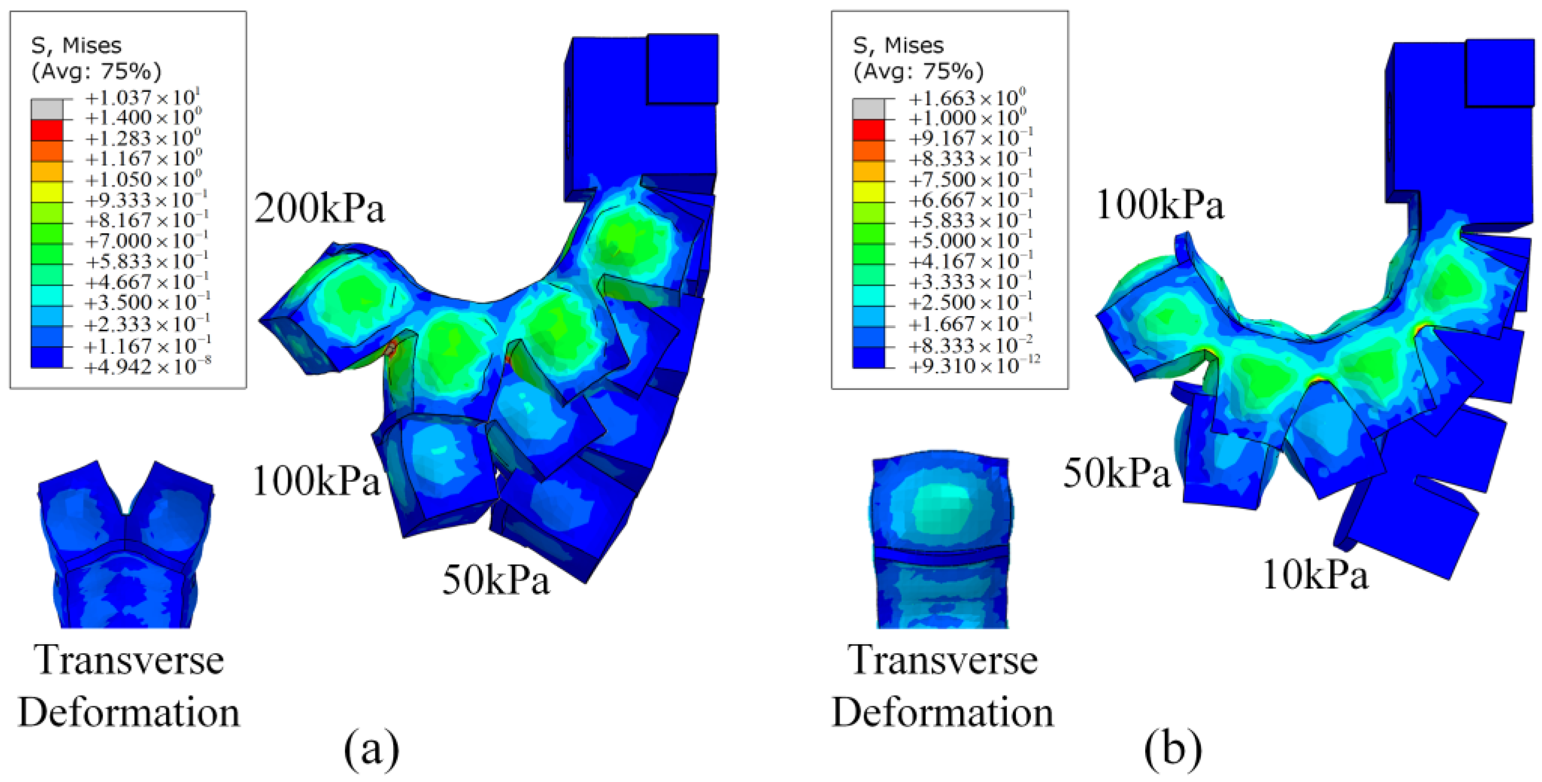
2.3. Actuation Simulation

FE modeling is a great numerical method for performing continuous piecewise approximation using known material parameters; which, provides an effective means to predict performance as well as optimize soft actuator designs [31,32,33]. The FE method discretizes the complex geometry into small elements (e.g., 10-node tetrahedral elements), using nodal values and shape functions (e.g., linear shape functions) to approximate the discretized elements. The assembly of all elements contributes to the solution of the whole domain; thus, converging to the true solution with refining procedure. In this study, FE models of both actuators were built in Abaqus 2020 (SIMULIA, Dassault System, Vélizy-Villacoublay, MA, France). The material DS30 was described as incompressible hyper-elastic rubber using the Ogden model [34], whose strain energy function is expressed as:
W = p = 1 N μ p α p λ 1 α p + λ 2 α p + λ 3 α p 3
where μ p and α p are the shear properties of the material; λ i is the constant for deviatoric principal stretch; N is model order [35]. Here, N = 2 , μ 1 = 1.98935431 × 10 5   MPa ,   α 1 = 1.23978721 × 10 1 , μ 2 = 3.65598858 × 10 1   MPa , and α 2 = 6.21412512 .
In each model, the bottom surface and two side surfaces of the actuator were fixed, and uniform pressures were applied to all the inner chamber surfaces. For meshing, we used 10-node hybrid quadratic tetrahedron elements (C3D10H), with a global mesh seed of 1 mm and a material density of 1080 kg/m3. An automatic step size was used in the simulation, and gravity was ignored due to its relatively small effect on the deformation. According to the simulation, as shown in Figure 3a,b, the herringbone actuator shows bending in both longitudinal and transverse directions; whereas, the regular actuator bends only in the longitudinal direction.

3. Results and Discussion

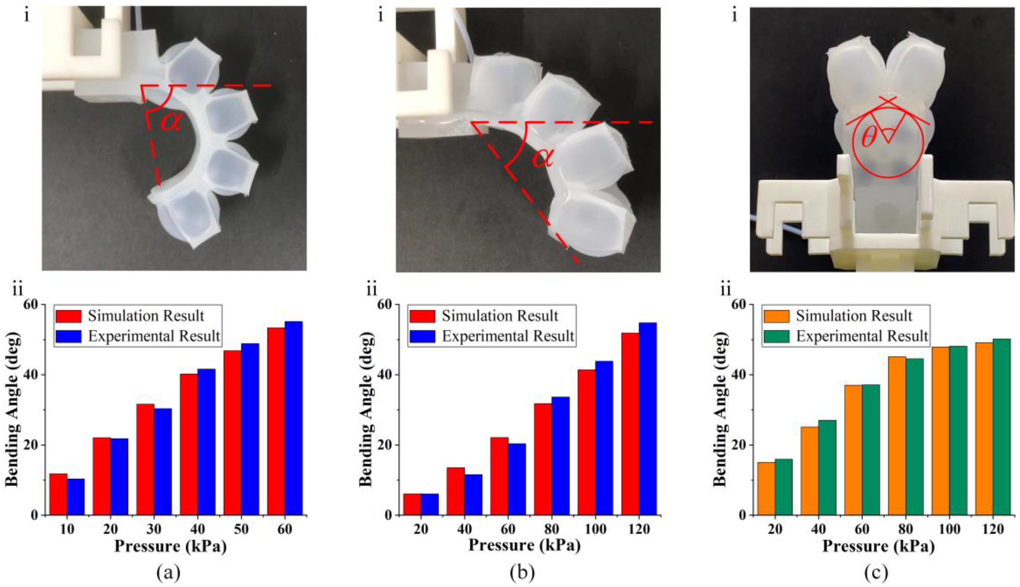
3.1. Inflation Deformation Characterization

To characterize the bending performance of the two actuators, we measured the longitudinal and the transverse bending angles of the prototype actuators at different inflation pressures. In the experimental platform of bending test, the positive pressure for actuator deformation was supplied by a pressure controller (OB1 Mk3 pressure control kit, ELVEFLOW, Paris, France) connected with a compressed air pump (FUJ-5L, Fujiwara, Taizhou, China). The actuator was assembled on the fixture and connected through its inflation port directly to the pressure controller, as illustrated in Figure 4. In the experiment, maximum inflation pressures of 60 kPa and 120 kPa were applied to the regular and herringbone actuators, respectively, while the bending deformations were captured by a smart phone camera with an effective pixel of 12 million (iPhone 13, Apple Inc., Cupertino, CA, USA).
Figure 4 illustrates how the bending angles of both the regular and herringbone actuators increase as inflation pressure increases. The regular shows a longitudinal bending angle that is substantially greater than the herringbone at the same pressure, just as in the simulation. For instance, as shown in Figure 4a, the herringbone reaches 13.52° at 40 kPa pressure compared to 40.17° for the regular. Similarly, when the input pressure is set to 60 kPa and 120 kPa, respectively, the two actuators produce around the same longitudinal bending angles (herringbone: 51.85°; regular: 53.36°). The transverse bending of the herringbone actuator is depicted in Figure 4c, which demonstrates that the deformation of the regular is concentrated along the longitudinal axis and that its transverse bending angle remains 0° throughout; while, the transverse bending angle of the herringbone initially increases quickly (from 0 to 80 kPa, with an average increase of 5.24° per step), then slows down as the pressure increases above 80 kPa. Our comparison of the test and simulation results shows a maximum variation of 7.04% for the herringbone transverse angle and 12.64% and 14.57% for the regular and herringbone longitudinal angle measurements, respectively.
It is also important to note that the regular actuator has a quicker response time than the herringbone actuator. This phenomenon can be explained by their structural differences. The herringbone actuator has eight chambers, and each chamber has an area of ~300 mm2. However, the regular actuator only has four chambers, which produces a single chamber area of ~600 mm2. Therefore, the same input pressure results in a greater force being generated in the chambers of the regular actuator, causing it to bend more and faster. In addition, the total chamber volume of the herringbone actuator is ~2678 mm3, which is smaller than that of the regular actuator (~3820 mm3). The actuator of the smaller chamber requires higher actuation pressure to bend fully [14]; hence, this explains the herringbone actuator’s requirement of higher pressures to achieve the same bending angle as the regular actuator.

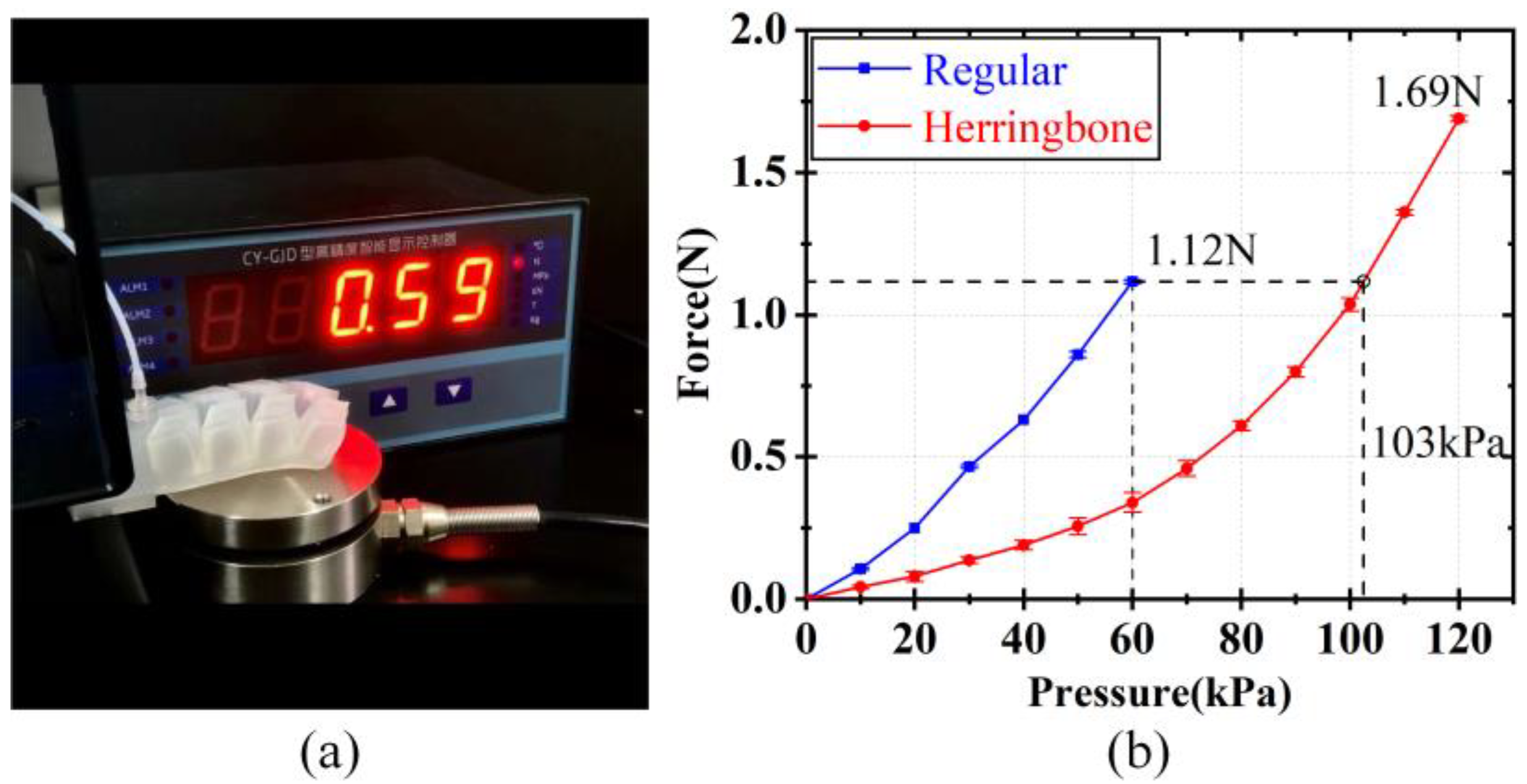
3.2. Blocking Force Test

The blocking force test is designed to investigate the actuator’s force capacity. It estimates the actuator’s maximum tip force as measured when its displacement is blocked. Similar to Hu et al. [12], we used a multi-axis force sensor (HZC-HI, ATI Automation, China; resolution: ±0.1%, stability: 0.05%, sensing range: up to 100 N) to measure the normal stress generated at the tip when the actuator is pressurized. As shown in Figure 5a, the end of the actuator was attached to a fixture; while, the tip was positioned freely on the multi-axis force sensor.
Figure 5b shows the blocking force of the regular and the herringbone actuators at various input pressures. Both actuators exhibit a rising blocking force with pressure; however, the regular actuator’s slope is steeper than the herringbone’s, meaning that for the same pressures, the blocking force former is greater than the latter. For instance, the herringbone only reaches 0.34 N at the same pressure as the regular; which, reaches 1.12 N at 60 kPa and requires almost twice as much pressure (~103 kPa) to produce the 1.12 N. Since the regular only bends in the longitudinal direction, the cumulative pressure from the air chambers is concentrated in the longitudinal direction and, hence, generates a lot of force at the tip. The herringbone, however, distributes the pressure in both the longitudinal and transverse directions; which, reduces the amount of pressure that reaches the end tip.

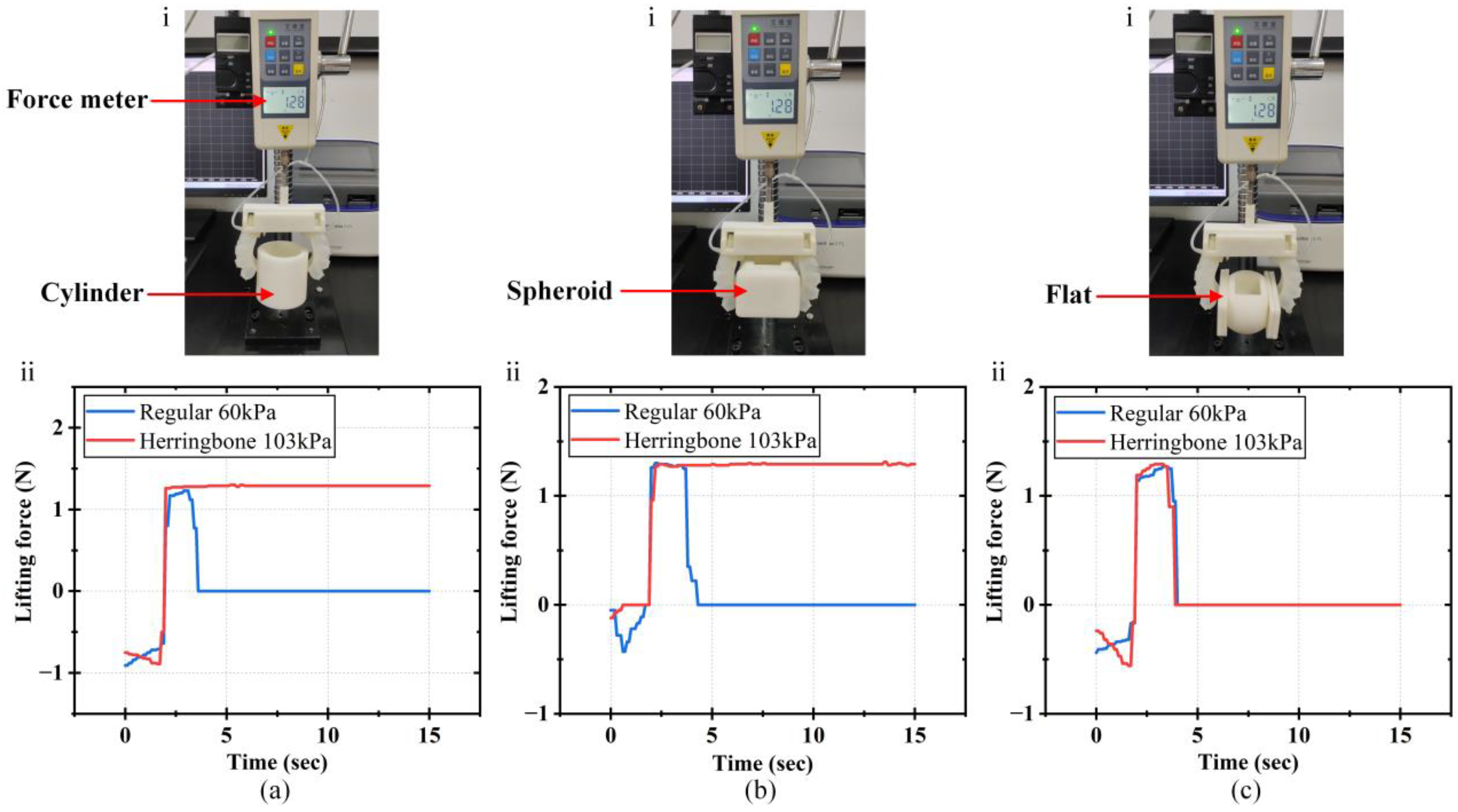
3.3. Lifting Ability Test

The lifting force is used to determine a soft gripper’s capacity to steadily lift multiple things. We assessed the lifting forces in the experimental setup depicted in Figure 6 to investigate the capacities of the two actuators. In the setup, a pair of actuators of the same dimension are assembled on a fixture that is attached to a digital force meter (HP-50, Yueqing Hampi Instrument Company, Yueqing, China; resolution: 0.01 N, error: ±0.5%). The actuators are inflated by the compressed air to bend and form a soft gripper. Once the gripper has successfully lifted the object, the force meter measures the lifting force. Here, we fabricated two types of soft grippers (i.e., regular and herringbone actuator-based). As the lifting ability of the gripper is significantly dependent on the blocking force of the actuator, we measured the lifting forces of the regular and the herringbone grippers at pressures of 60 kPa and 103 kPa, respectively, to study and compare the lifting functionalities of the two grippers (Figure 6). Thus, the actuators of the two grippers could generate the same blocking forces while fully grasping the objects.
As seen in Figure 6a,b, the regular gripper can lift the cylinder and the spheroid (both weighing ~1.28 N) for a brief period of time while being subjected to an input pressure of 60 kPa. Due to the gripper’s one-directional (longitudinal) bending, the lifting is unstable because of the limited contact area between it and the object. Unlike the regular gripper, the herringbone gripper offers high conformal bending (in both longitudinal and transverse directions), providing sufficient contact area (i.e., curved surface) for the stable and steady lifting of the objects. Next, we investigated the grippers’ performances with flat surfaces. As shown in Figure 6c, both grippers only lifted the flat object briefly before falling off balance, resulting in very comparable force curves. This can be attributed to inadequate contact and blocking forces; which, would otherwise provide sufficient friction and lift forces for stable lifting.
Conventional lifting force testing often involves measuring the peak and instantaneous pull forces on test objects mounted to a platform [17,21]. This method is, however, insufficient to adequately represent the gripper’s lifting capacity. Instead, we employed a dynamic method that involved lifting the test objects and tracking their respective stabilities over a period of time. Ultimately, compared to the regular gripper, the herringbone gripper demonstrated greater stability when lifting objects, particularly those with curved surfaces.

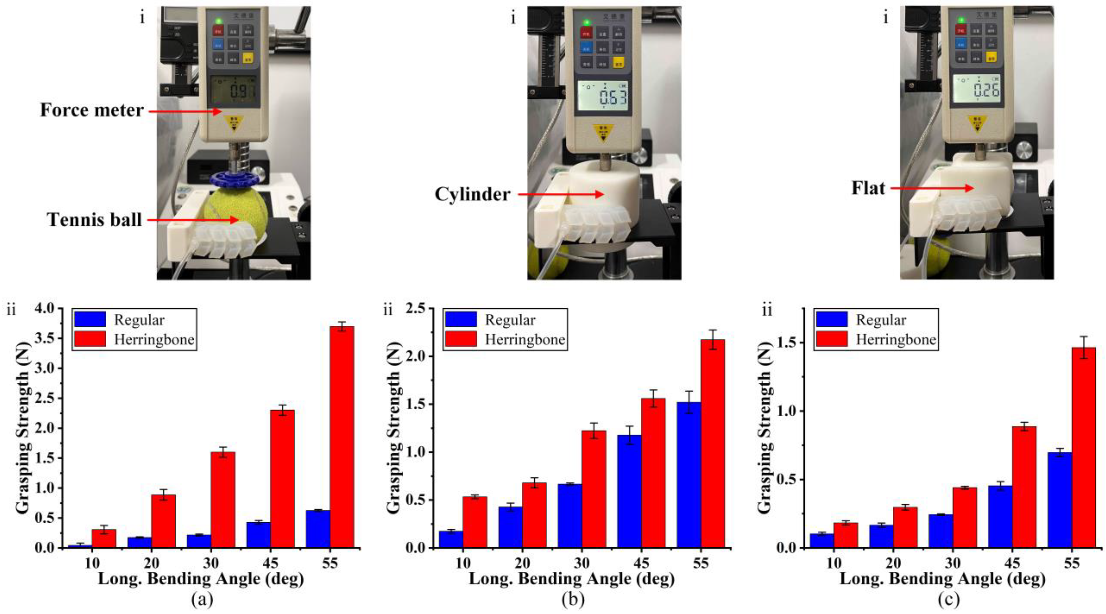
3.4. Grasping Strength Test

A gripper’s ability to firmly hold an object can be measured using the gripping force; which, is applied to counteract the lateral push or inertial forces of objects during horizontal movement. We measured the grasping forces at various bending angles of the actuators in order to analyze and contrast the grasping strengths of the two grippers (Figure 7). To make a common ground for comparison, we chose five sets of input pressures—based on the findings of the bending angle experiment (Figure 4a,b)—that allowed for equal bending of the regular and herringbone grippers. The input pressures used in the test and their corresponding longitudinal bending angles are shown in Table S1.
In the experiment, the gripper is mounted horizontally to a fixture, and a digital force meter is used to push the objects from within the grasp of the gripper while simultaneously measuring the required force. Figure 7a illustrates the measured grasping forces of both grippers on a ball. The grasp forces of both grippers increase as their bending (with respect to their inflation pressure) increases, illustrative of the increased grasping strength induced by the gripper deformation. Additionally, at each set of bending angles, the herringbone gripper’s grasping forces are significantly higher than those of the regular gripper (by more than 5 times), and as the bending angle increases, this force difference between the two grippers increases, reaching up to a maximum of 3.07 N at an angle of 55°. This is explained by the herringbone gripper’s conformal grasping capability. The gripper’s grasping forces increase as its area of contact with the ball expands, distributing more evenly in the longitudinal and transverse directions to hold the ball firmly, as opposed to the regular gripper’s force output; which, primarily concentrates on the tip and, hence, unable to secure the ball adequately. Furthermore, the grasping forces of the herringbone gripper were observed to be higher than the regular on cylindrical as well as flat surfaces, as shown in Figure 7b,c. However, in both cases, the transverse herringbone deformation does not greatly increase the contact area; rather, the gripping forces mostly result from contact with the side edges of the grippers, which make the force difference less noticeable.

3.5. Suction Force Test

In this part, we examine the soft actuator’s performance when using built-in suction pads to create a suction-gripping force. The experiment included single actuators and four-finger (actuator) grippers with suction pads of 13 mm and 16 mm diameters. As shown in the schematic diagram of the experimental setup for the suction force test (Figure 8a), the actuator is clamped horizontally under a digital force meter. Negative pressure is supplied to the actuator using a diaphragm pump (HLVP8-B24, Karmor Corporation, Shanghai, China) integrated with a pressure sensor (PSAN-C01CV, Autonics Corporation, Kyungnam, Republic of Korea) and a bypass relief valve. To measure the suction force, the actuator is first lowered to make contact with a glass positioned on the platform (Figure 8a), and then the relief valve is set to the desired negative pressure before turning on the diaphragm pump. After that, the actuator is then slowly lifted from the glass by lifting the lever while the force gauge measures and records the corresponding forces.
Figure 8b,c illustrate the suction forces of the single actuator and the four actuators. The suction forces of the single actuator with the 16 mm pad and the 13 mm pad both increase continuously as the negative pressure increases, as illustrated in Figure 8b. The 16 mm pad, however, produces a much higher suction force than its counterpart, measuring maximum suction forces of 10 N and 7.54 N at the pressure of −80 kPa, respectively. Similarly, for the grippers, the combined suction force also increased with pressure. The forces are, however, not as linear as with the single actuator; the maximum suction forces are 35 N and 24.5 N at a pressure of −80 kPa, respectively, which is approximately 3.5 times that of a single actuator. This can be attributed to the asynchronous disengagement of the four suction pads of the actuators. The maximum suction force is less than the combined forces of the individual actuators because only one of the suction pads is forced to leave the platform at first, while the rest either stay in place or slowly disengage later.

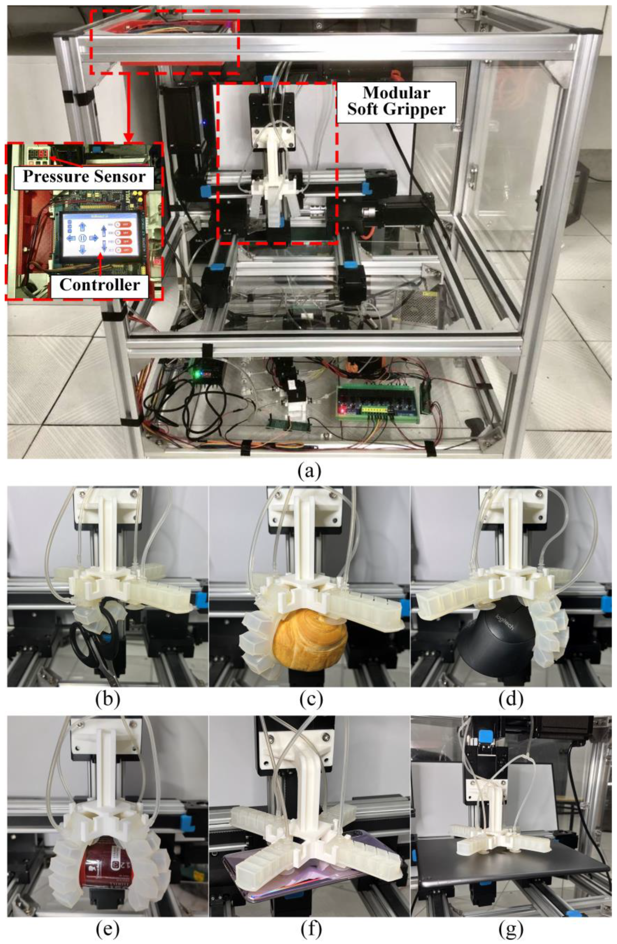
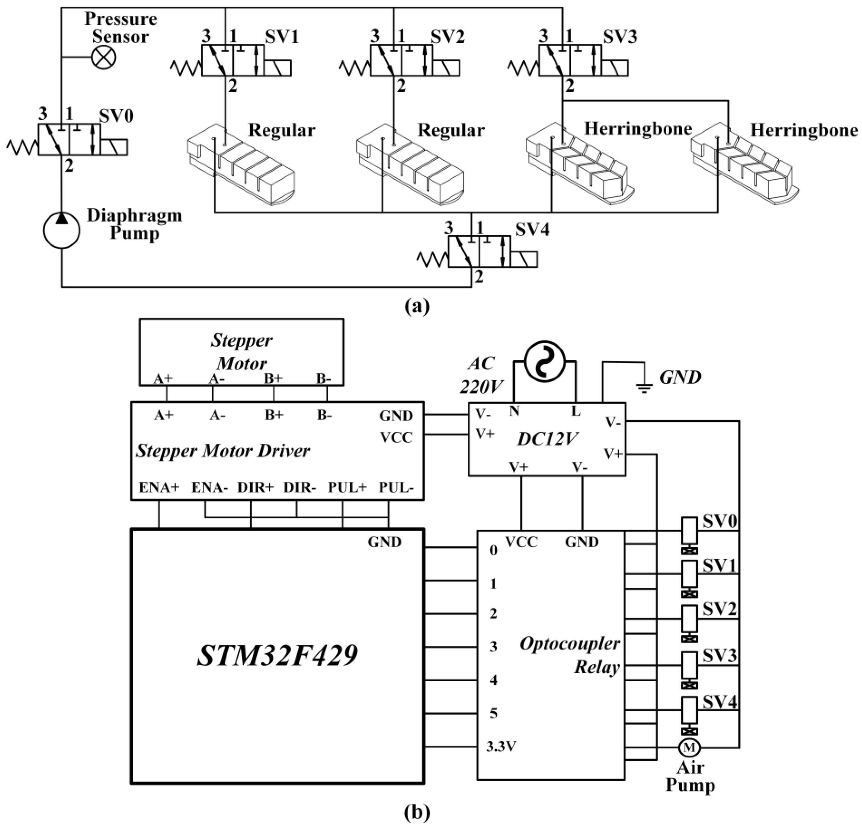
3.6. Automation Application

As described earlier, the regular actuator has the advantages of larger longitudinal bending deformation and higher blocking force under the same actuation pressures; while, the herringbone actuator performs better in grasping and lifting with the same longitudinal bending angles. To demonstrate the combined advantages of the two actuators, we integrated the two actuators into a modular gripper. Additionally, we developed automatic equipment that is able to load the modular gripper (Figure 9a), and we studied the modular gripper’s capacity to grasp different kinds of objects. The schematic diagrams of the pneumatic and the electric systems of the equipment are shown in Figure 10. The equipment mainly includes a controller, a diaphragm pump, a pressure sensor, five solenoid valves (SV), three sets of slide guides with stepped motors, mechanical components, and other necessary components of electrical and pneumatic systems.
Table 1 shows the switching combinations of the diaphragm pump and the solenoid valves for the different working modes of the modular gripper in the automation equipment. The equipment is programmed such that either of the two regular actuators can be inflated to work as a hook by opening SV1 or SV2, respectively. To grasp soft objects, the two regular actuators work together by opening SV1 and SV2 simultaneously. To grasp objects of irregular appearance, the two herringbone actuators work together by opening SV3. To grasp heavy objects, the four actuators work together by opening SV1, SV2, and SV3 simultaneously. For thin objects (e.g., paper, plate, laptop, etc.), SV4 is opened to produce strong vacuum suction forces on the bottom of the four actuators. Based on the above five working modes, the modular gripper can be used to grasp various kinds of objects.
According to the design, we set the gripper to perform the “Hook mode” based on the significant longitudinal bending advantage of the regular actuator. The “Hook mode” is used to lift the objects with the ring structures, such as a scissor (Figure 9b). The “Soft grasping mode” uses the bending of the two regular actuators to grasp the object. As the regular actuators can be actuated at low pressures, the “Soft grasping mode” is applied for grasping soft lightweight objects, such as bread (Figure 9c), a wooden block (Figure S2a), and a beaker (Figure S2b). In the “Irregular grasping mode”, both of the herringbone actuators bend to grasp objects. Two actuators were sufficient to securely grasp objects with irregular shapes, such as the mouse in Figure 9d, thanks to its conformal deformation characteristic. For round objects, the grasping effect is much better due to the tight fitting between the actuator and the object, such as a tennis ball with a glue (Figure S2c) and a tennis ball with a wrench (Figure S2d). The “Heavy grasping mode” is applied to grasp the heavy objects. Since all the four actuators could be bent to hold the objects like a palm, high grasping strength and lifting force can be achieved, as with a jar (130.1 g, Figure 9e) and a tennis ball with a glue and a wrench (354.3 g, Figure S2e). Finally, we applied the “Vacuum suction mode” to suck and lift the thin objects by using the vacuum suction force of the gripper, as with a mobile phone (Figure 9f) and a laptop (Figure 9g). It is worth noting that the gripper can suck and lift even larger and heavier objects. For example, the gripper can lift a laptop with a heavy box of 1199 g weight (Figure S2f). For weights and sizes that the grasp mode alone cannot lift, the “Vacuum suction mode” with its strong suction force would suffice. The weights of all the objects mentioned above are listed in Table 2 and Table S2.

4. Conclusions

This work presents a modular soft gripper, consisting of two types of SPA-based actuators—the regular actuator and the herringbone actuator. The bending features of the two actuators were first studied by FE simulations and then validated by experiments including the blocking force test, lifting test, grasping strength test, and suction force test. The experimental results showed that the regular actuator had the advantages of fast bending response and large blocking force; while, the herringbone actuator had better performance on lifting stability and grasping strength due to its unique conformal deformation characteristic. Based on the advantages of the two actuators, a modular soft gripper was developed with five operational modes: hook mode, soft grasping mode, irregular grasping mode, heavy grasping mode, and vacuum suction mode. To validate the practical application of the gripper, automation equipment was developed to load and run the gripper based on some custom program codes. The experiments show that the gripper is capable of manipulating (i.e., hooking/grasping/sucking) a wide variety of objects (e.g., light to heavy, small to large). Overall, we demonstrated the multifunctional characteristics of the proposed modular soft gripper; which, performed different working modes for various tasks, thereby increasing device flexibility and efficiency compared to the traditional single-function SPA-based soft grippers. We believe this work would provide insights for more robust designs of soft grippers, particularly with improved modular characteristics and multifunctionality, towards larger application scopes.

Supplementary Materials

The following supporting information can be downloaded at: https://www.mdpi.com/article/10.3390/act12040172/s1, Figure S1: Schematic diagram of the actuator fabrication process; Figure S2: Snapshots of the function tests of the modular soft gripper; Table S1: The required input pressures versus the longitudinal bending angles; Table S2: Object shapes and weights; Mold 1: Bottom chamber (herringbone); Mold 2: Bottom chamber (regular); Mold 3: Bottom; Mold 4: Top chamber (herringbone); Mold 5: Top chamber (regular).

Author Contributions

Conceptualization, X.Z.; Data curation, S.Y.; Formal analysis, F.L.; Funding acquisition, X.Z.; Investigation, S.Y., J.D., L.L. and N.D.; Methodology, X.Z. and S.Y.; Project administration, X.Z.; Resources, X.Z.; Software, S.Y. and J.D.; Supervision, X.Z.; Visualization, J.D.; Writing—original draft, S.Y.; Writing—review and editing, X.Z., A.E.O. and F.L. All authors have read and agreed to the published version of the manuscript.

Funding

This research was funded by the National Natural Science Foundation of China (No. 51905150), the Fundamental Research Funds for the Central Universities (No. B220202024), Changzhou Science and Technology Bureau Program (No. CE20225046), China Postdoctoral Science Foundation (2020T130097), and National College Student Innovation and Entrepreneurship Training Program (No. 202210294009Z).

Institutional Review Board Statement

Not applicable.

Informed Consent Statement

Not applicable.

Data Availability Statement

The data used to support the findings of this study are included within the article.

Conflicts of Interest

The authors declare no conflict of interest.

References

  1. Shintake, J.; Cacucciolo, V.; Floreano, D.; Shea, H. Soft robotic grippers. Adv. Mater. 2018, 30, 1707035. [Google Scholar] [CrossRef] [Green Version]
  2. Yap, H.K.; Ng, H.Y.; Yeow, C.-H. High-Force Soft Printable Pneumatics for Soft Robotic Applications. Soft Robot. 2016, 3, 144–158. [Google Scholar] [CrossRef]
  3. Zhang, X.; Oseyemi, A.E.; Ma, K.; Yu, S. Entirely soft valve leveraging snap-through instability for passive flow control. Sens. Actuators B Chem. 2022, 367, 132035. [Google Scholar] [CrossRef]
  4. Wang, W.; Rodrigue, H.; Kim, H.-I.; Han, M.-W.; Ahn, S.-H. Soft composite hinge actuator and application to compliant robotic gripper. Compos. Part B Eng. 2016, 98, 397–405. [Google Scholar] [CrossRef]
  5. Lau, G.-K.; Heng, K.-R.; Ahmed, A.S.; Shrestha, M. Dielectric elastomer fingers for versatile grasping and nimble pinching. Appl. Phys. Lett. 2017, 110, 182906. [Google Scholar] [CrossRef]
  6. Amend, J.; Lipson, H. The JamHand: Dexterous Manipulation with Minimal Actuation. Soft Robot. 2017, 4, 70–80. [Google Scholar] [CrossRef]
  7. Van Meerbeek, I.M.; Mac Murray, B.C.; Kim, J.W.; Robinson, S.S.; Zou, P.X.; Silberstein, M.N.; Shepherd, R.F. Morphing Metal and Elastomer Bicontinuous Foams for Reversible Stiffness, Shape Memory, and Self-Healing Soft Machines. Adv. Mater. 2016, 28, 2801–2806. [Google Scholar] [CrossRef] [PubMed]
  8. Tang, Y.; Chi, Y.; Sun, J.; Huang, T.-H.; Maghsoudi, O.H.; Spence, A.; Zhao, J.; Su, H.; Yin, J. Leveraging elastic instabilities for amplified performance: Spine-inspired high-speed and high-force soft robots. Sci. Adv. 2020, 6, eaaz6912. [Google Scholar] [CrossRef] [PubMed]
  9. Ang, B.W.K.; Yeow, C.-H. Design and Modeling of a High Force Soft Actuator for Assisted Elbow Flexion. IEEE Robot. Autom. Lett. 2020, 5, 3731–3736. [Google Scholar] [CrossRef]
  10. Glick, P.; Suresh, S.A.; Ruffatto, D.; Cutkosky, M.; Tolley, M.T.; Parness, A. A Soft Robotic Gripper With Gecko-Inspired Adhesive. IEEE Robot. Autom. Lett. 2018, 3, 903–910. [Google Scholar] [CrossRef]
  11. Dilibal, S.; Sahin, H.; Danquah, J.O.; Emon, O.F.; Choi, J.-W. Additively Manufactured Custom Soft Gripper with Embedded Soft Force Sensors for an Industrial Robot. Int. J. Precis. Eng. Manuf. 2021, 22, 709–718. [Google Scholar] [CrossRef]
  12. Hu, W.; Alici, G. Bioinspired Three-Dimensional-Printed Helical Soft Pneumatic Actuators and Their Characterization. Soft Robot. 2020, 7, 267–282. [Google Scholar] [CrossRef] [PubMed]
  13. Zhong, G.; Hou, Y.; Dou, W. A soft pneumatic dexterous gripper with convertible grasping modes. Int. J. Mech. Sci. 2019, 153–154, 445–456. [Google Scholar] [CrossRef]
  14. Connolly, F.; Polygerinos, P.; Walsh, C.J.; Bertoldi, K. Mechanical Programming of Soft Actuators by Varying Fiber Angle. Soft Robot. 2015, 2, 26–32. [Google Scholar] [CrossRef] [Green Version]
  15. Li, S.; Vogt, D.M.; Rus, D.; Wood, R.J. Fluid-driven origami-inspired artificial muscles. Proc. Natl. Acad. Sci. USA 2017, 114, 13132–13137. [Google Scholar] [CrossRef] [PubMed] [Green Version]
  16. Zhang, X.; Oseyemi, A.E. A herringbone soft pneu-net actuator for enhanced conformal gripping. Robotica 2021, 40, 1345–1360. [Google Scholar] [CrossRef]
  17. Wang, T.; Ge, L.; Gu, G. Programmable design of soft pneu-net actuators with oblique chambers can generate coupled bending and twisting motions. Sens. Actuators A Phys. 2018, 271, 131–138. [Google Scholar] [CrossRef]
  18. Mosadegh, B.; Polygerinos, P.; Keplinger, C.; Wennstedt, S.; Shepherd, R.; Gupta, U.; Shim, J.; Bertoldi, K.; Walsh, C.J.; Whitesides, G.M. Pneumatic Networks for Soft Robotics that Actuate Rapidly. Adv. Funct. Mater. 2014, 24, 2163–2170. [Google Scholar] [CrossRef] [Green Version]
  19. Zhang, Y.F.; Zhang, N.B.; Hingorani, H.; Ding, N.; Wang, D.; Yuan, C.; Zhang, B.; Gu, G.; Ge, Q. Fast-response, Stiffness-tunable soft actuator by hybrid multimaterial 3D printing. Adv. Funct. Mater. 2019, 29, 1806698. [Google Scholar] [CrossRef]
  20. Xavier, M.S.; Tawk, C.D.; Zolfagharian, A.; Pinskier, J.; Howard, D.; Young, T.; Lai, J.; Harrison, S.M.; Yong, Y.K.; Bodaghi, M. Soft Pneumatic Actuators: A Review of Design, Fabrication, Modeling, Sensing, Control and Applications. IEEE Access 2022, 10, 59442–59485. [Google Scholar] [CrossRef]
  21. Su, H.; Hou, X.; Zhang, X.; Qi, W.; Cai, S.; Xiong, X.; Guo, J. Pneumatic Soft Robots: Challenges and Benefits. Actuators 2022, 11, 92. [Google Scholar] [CrossRef]
  22. Pagoli, A.; Chapelle, F.; Corrales-Ramon, J.-A.; Mezouar, Y.; Lapusta, Y. Review of soft fluidic actuators: Classification and materials modeling analysis. Smart Mater. Struct. 2022, 31, 013001. [Google Scholar] [CrossRef]
  23. Polygerinos, P.; Lyne, S.; Wang, Z.; Nicolini, L.F.; Mosadegh, B.; Whitesides, G.M.; Walsh, C.J. Towards a Soft Pneumatic Glove for Hand Rehabilitation. In Proceedings of the IEEE/RSJ International Conference on Intelligent Robots and Systems (IROS), Tokyo, Japan, 3–7 November 2013. [Google Scholar]
  24. Wang, Z.; Or, K.; Hirai, S. A dual-mode soft gripper for food packaging. Robot. Auton. Syst. 2020, 125, 103427. [Google Scholar] [CrossRef]
  25. Schiller, L.; Seibel, A.; Schlattmann, J. Toward a Gecko-Inspired, Climbing Soft Robot. Front. Neurorobot. 2019, 13, 106. [Google Scholar] [CrossRef] [Green Version]
  26. Yang, P.; Wang, X.; Dang, F.; Yang, Z.; Liu, Z.; Yan, Y.; Zhu, L.; Liu, Y.; Xiao, H.; Chen, X.; et al. Elementary Slender Soft Robots Inspired by Skeleton Joint System of Animals. Soft Robot. 2019, 6, 377–388. [Google Scholar] [CrossRef]
  27. Justus, K.B.; Hellebrekers, T.; Lewis, D.D.; Wood, A.; Ingham, C.; Majidi, C.; LeDuc, P.R.; Tan, C. A biosensing soft robot: Autonomous parsing of chemical signals through integrated organic and inorganic interfaces. Sci. Robot. 2019, 4, eaax0765. [Google Scholar] [CrossRef]
  28. Li, H.; Yao, J.; Zhou, P.; Chen, X.; Xu, Y.; Zhao, Y. High-force soft pneumatic actuators based on novel casting method for robotic applications. Sens. Actuators A Phys. 2020, 306, 111957. [Google Scholar] [CrossRef]
  29. Marchese, A.D.; Onal, C.D.; Rus, D. Autonomous Soft Robotic Fish Capable of Escape Maneuvers Using Fluidic Elastomer Actuators. Soft Robot. 2014, 1, 75–87. [Google Scholar] [CrossRef] [Green Version]
  30. Marchese, A.D.; Katzschmann, R.; Rus, D. A Recipe for Soft Fluidic Elastomer Robots. Soft Robot. 2015, 2, 7–25. [Google Scholar] [CrossRef] [Green Version]
  31. Elsayed, Y.; Vincensi, A.; Lekakou, C.; Geng, T.; Saaj, C.M.; Ranzani, T.; Cianchetti, M.; Menciassi, A. Finite Element Analysis and Design Optimization of a Pneumatically Actuating Silicone Module for Robotic Surgery Applications. Soft Robot. 2014, 1, 255–262. [Google Scholar] [CrossRef] [Green Version]
  32. Polygerinos, P.; Wang, Z.; Overvelde, J.T.B.; Galloway, K.C.; Wood, R.J.; Bertoldi, K.; Walsh, C.J. Modeling of Soft Fiber-Reinforced Bending Actuators. IEEE Trans. Robot. 2015, 31, 778–789. [Google Scholar] [CrossRef] [Green Version]
  33. Moseley, P.; Florez, J.M.; Sonar, H.A.; Agarwal, G.; Curtin, W.; Paik, J. Modeling, Design, and Development of Soft Pneumatic Actuators with Finite Element Method. Adv. Eng. Mater. 2015, 18, 978–988. [Google Scholar] [CrossRef]
  34. Marechal, L.; Balland, P.; Lindenroth, L.; Petrou, F.; Kontovounisios, C.; Bello, F. Toward a Common Framework and Database of Materials for Soft Robotics. Soft Robot. 2021, 8, 284–297. [Google Scholar] [CrossRef]
  35. Ogden, R.W. Large Deformation Isotropic Elasticity—On the Correlation of Theory and Experiment for Incompressible Rubberlike Solids. Proc. Math. Phys. Eng. Sci. 1997, 326, 565–584. [Google Scholar] [CrossRef]
Figure 1. Schematic structures of the modular soft gripper and the actuators. (a) Exploded view of the soft gripper. (b) Vertical assembly and (c) horizontal assembly of the gripper. (d) The regular actuator. (e) The herringbone actuator.
Actuators 12 00172 g001
Figure 2. The prototype actuators and modular soft gripper. (a) Top and (b) bottom views of the herringbone actuator. (c) Top and (d) bottom views of the regular actuator. (e) The modular gripper with the actuators assembled (e) vertically and (f) horizontally.
Actuators 12 00172 g002
Figure 3. FE simulation results of (a) the herringbone actuator and (b) the regular actuator.
Actuators 12 00172 g003
Figure 4. (a) Bending behavior of the regular actuator (i), and the bending angle comparisons (ii). (b) Longitudinal bending behavior of the herringbone actuator (i), and the longitudinal bending angle comparisons (ii). (c) Transverse bending behavior of the herringbone actuator (i), and the transverse bending angle comparisons (ii).
Actuators 12 00172 g004
Figure 5. Blocking force test. (a) Experimental set up for the measurement of blocking force. (b) Blocking forces of actuators under different input pressures. Each test is repeated five times, and the error bars indicate the standard deviation of the measurements.
Actuators 12 00172 g005
Figure 6. Lifting force test of the soft gripper. The soft gripper lifts (a) a cylindrical part, (b) a spheroid, and (c) a flat. Figures (i) show the snapshots of the lifting experiments, and Figures (ii) show the measured lifting forces of the different objects.
Actuators 12 00172 g006
Figure 7. Grasping strength test of the soft gripper. Grasping test using (a) a ball, (b) a cylindrical part, and (c) a flat part. Figures (i) show the snapshots of the grasping experiments, and Figures (ii) show the measured grasping forces of the different objects at different longitudinal bending angles.
Actuators 12 00172 g007
Figure 8. Suction force test. (a) Schematic diagram of the experimental setup. Suction forces under different negative pressure inputs when using (b) a single suction pad and (c) four suction pads.
Actuators 12 00172 g008
Figure 9. Picture of the automatic equipment loading the modular soft gripper (a) and snapshots of various object lifting applications on: (b) a scissor, (c) a bread, (d) a mouse, (e) a jar, (f) a mobile phone, and (g) a laptop.
Actuators 12 00172 g009
Figure 10. Schematic diagram of (a) the pneumatic and (b) the electric system of the automatic equipment.
Actuators 12 00172 g010
Table 1. Switching combinations of the diaphragm pump and the solenoid valves for different working modes of the modular gripper.
ModePumpSV0SV1SV2SV3SV4
IdleOffOffOffOffOffOff
HookOnOnOn/OffOff/OnOffOff
Soft graspingOnOnOnOnOffOff
Irregular graspingOnOnOffOffOnOff
Heavy graspingOnOnOnOnOnOff
Vacuum suctionOnOffOffOffOffOn
Table 2. Object shapes and weights.
ObjectShape/CharacteristicWeight (g)
ScissorRing31.1
BreadSoft47.6
MouseIrregular90.1
JarCylinder130.1
Mobile phoneFlat/Thin173.1
LaptopFlat/Heavy463.0
Disclaimer/Publisher’s Note: The statements, opinions and data contained in all publications are solely those of the individual author(s) and contributor(s) and not of MDPI and/or the editor(s). MDPI and/or the editor(s) disclaim responsibility for any injury to people or property resulting from any ideas, methods, instructions or products referred to in the content.

