1. Introduction
Aluminum thin-walled components are highly sought after in the aviation and aerospace industries given their excellent mechanical properties, such as the overall partition frame, integral ribs, integral panels, and other non-universal thin-walled parts. The processing method is mostly based on the milling process [
1]. A certain type of aluminum alloy antenna has the advantages of a high gain, small size, light weight, and easy installation, so it is widely used in various series of precision tracking radar systems. With the development of antenna components toward integration, higher requirements for machining accuracy and efficiency have been put forward. However, the antenna components belong to the thin-walled plate components, which have the characteristics of a large size, complex structure, low stiffness, and large material removal rate. These factors are not conducive to milling. After a series of complex processes, it is difficult to ensure that they do not deform. The typical aerospace part undergoes several processes, e.g., forging, rolling, heat treatment, rough machining, etc., before coming to the final finishing stage. Since the generation of residual stress runs through the whole life cycle of component blank forming and processing, residual stress is the main cause of machining deformation for aluminum alloy thin-walled components [
2].
Many thin-walled components are milled to remove more than 90% of the initial blank, and the IRS can influence distortion in machined parts [
3]. Many studies have shown that the IRS is the main cause of the deformation of thin-walled components [
4,
5,
6]. At the same time, when the blank containing IRS undergoes subsequent machining, the superposition of external load and residual stress breaks the internal stress balance. Machining-induced residual stress introduced after stress rebalancing has a significant effect on the deformation of subsequent processes [
7,
8]. In the static stage after processing, the residual stress field in the component begins to release due to the influence of ambient temperature, which causes a secondary deformation of the component. This undoubtedly increases the difficulty of subsequent processing and also challenges the dimensional stability of the component.
For the milling of the aluminum alloy sheet, Huang et al. found that the coupling of the initial compressive residual stress field and the subsequent machining-induced residual stress will increase the deformation, whereas the coupling of the initial tensile residual stress field and the machining-induced residual stress will reduce the deformation. It is worth noting that machining-induced residual stress is the main reason for the deformation of the aluminum sheet when its thickness is less than 1.25 mm [
9].
Ritin et al. employed a three-dimensional end milling model to simulate the deformation of billets with different initial stress distributions along multiple milling paths. The coupling effect of IRS and MIRS on the milling deformation of a C-groove thin-walled structure was revealed [
10]. The results show that the interaction between IRS and MIRS is nonlinear due to the influence of the component structure and local stress. The nonlinear interaction and milling path have a great influence on the final machining deformation. In order to predict the residual stress distribution and the influence of subsequent machining deformation in more detail, Gao et al. presented a semi-analytical model for a thin-walled parts deformation prediction that was validated by a corresponding FEM approach and experiments. It is considered that controlling and reducing the stress distribution in the length direction and the top stress distribution in the blank will help to reduce the machining deformation. If the residual stress is symmetrically distributed in the neutral plane along the thickness direction, the final machining deformation depends on the residual stress distribution of a certain thickness below the surface of the blank [
11]. When analyzing the deformation of bulk residual stress on subsequent machining, Werke et al. obtained the residual stress distribution of the part after the previous machining using the contour method, which was used as an input to simulate subsequent machining deformation, thereby reducing the simulation analysis steps and calculation time [
12]. Based on the finite element method, Rahul Y et al. predicted the residual stress distribution on the surface and sub-surface of TC4 micro-end milling, and proved the consistency of the milling model through experiments [
13]. Li et al. analyzed the influence of the cutting depth on residual stress redistribution and its influence on the deformation of aluminum alloy thin-walled components, and proposed a more accurate method to predict the contour and amplitude of residual stress distribution. In addition, they also found that reducing the residual stress difference between the surface and subsurface of the component after milling is beneficial for reducing the machining deformation [
14]. However, in the application of the finite element method for predicting IRS and MIRS, there are still two problems to be faced: (1) it is necessary to divide a large number of detailed meshes on the surface of the model during the calculation so as to improve the calculation efficiency and reduce the calculation cost; (2) at present, the residual stress detection for thin-walled components is mostly surface detection, and how much this residual stress will affect the subsequent processing deformation still needs further quantitative analysis.
The lack of residual stress variation and a control law is the root cause of the out-of-tolerance milling deformation of thin-walled components. Therefore, a major way to improve the deformation is to combine the residual stress detection and machining deformation to form feedback and optimize the original process parameters. Daniel Weber et al. combined experiments and FEM to reduce deformation by optimizing the milling path of aluminum alloy thin-walled cavities [
15]. Zhang et al. proposed a method to control the clamping state during the milling process. By relaxing the fixture in an orderly manner during the milling process, the machining-induced residual stress is balanced with the internal stress to avoid the redistribution of residual stress. Compared with the fixture that is not relaxed after rough milling and the fixture that is completely relaxed, the orderly control of fixture relaxation can significantly reduce the milling deformation of the blade [
16].
For most thin-walled components, the deformation can be improved by optimizing milling parameters, milling paths, and tightening forces, but the residual stress cannot be eliminated completely, and the deformation caused by residual stress is still faced in the subsequent machining process. Therefore, it is often necessary to introduce one or more stress relief processes in the blank stage and key processes of thin-walled components, such as pre-stretching, annealing stress relief, the vibration aging method, and so on. Unfortunately, the roll forming and quenching of the aluminum sheet introduces residual stresses in the billet, which are difficult to significantly relieve via heat treatment without the degradation of mechanical properties [
17]. Moreover, uniaxially stretching the material to plastic strains of 1.5 to 3% can also help to reduce the amplitude of residual stress to a certain extent. Regarding the vibration aging method, based on the structure, shape, materials, and other components used to determine the different process parameters, the process is complex and difficult to master, and, for thin-walled components, it is difficult to maintain their dimensional accuracy after vibration aging [
18]. Thus, a new ultrasonic destressing process has been gradually derived. The ultrasonic transducer is arranged in the area where the residual stress is too large, and the energy is injected into the component by high-frequency vibration to induce the residual stress to be released [
19,
20]. In previous studies, we also used this method to realize the machining deformation control of tiny titanium alloy thin-walled components. The experimental results show that the ultrasonic stress relief method has the characteristics of a short useful time and high residual stress elimination rate compared with the traditional stress relief process [
21].
In summary, the current research on the milling deformation of thin-walled components caused by residual stress is mainly focused on the finite element method used to predict machining deformation and optimize machining parameters. For large-sized and high-precision aluminum alloy thin-walled antenna components, applying the existing stress relief process method is insufficient. It is necessary to carry out ultrasonic stress relief research in combination with its structural characteristics and milling process. In this paper, the residual stress distribution of wrought aluminum 5A06/6061/7075 alloy plate parts, both as blanks and after milling, were tested using the ultrasonic critical refraction longitudinal wave method (LCR wave method). Combined with the three-coordinate measurement method, the influence of the IRS on the subsequent milling deformation and the influence of the MIRS on the secondary milling deformation were compared and analyzed. Meanwhile, an ultrasonic residual stress relief process suitable for the Al alloy thin-walled component of a leaky antenna was proposed, and the corresponding experiment was carried out with a self-made ultrasonic platform. Finally, the effectiveness and feasibility of the ultrasonic regulation process for the deformation control of thin-walled components were verified by the step-by-step control of an initial residual stress field and machining-induced residual stress field.
2. Ultrasonic Detection, Regulation Methods, and Instrument
2.1. Ultrasonic Critical Refraction Longitudinal Wave Detection Method
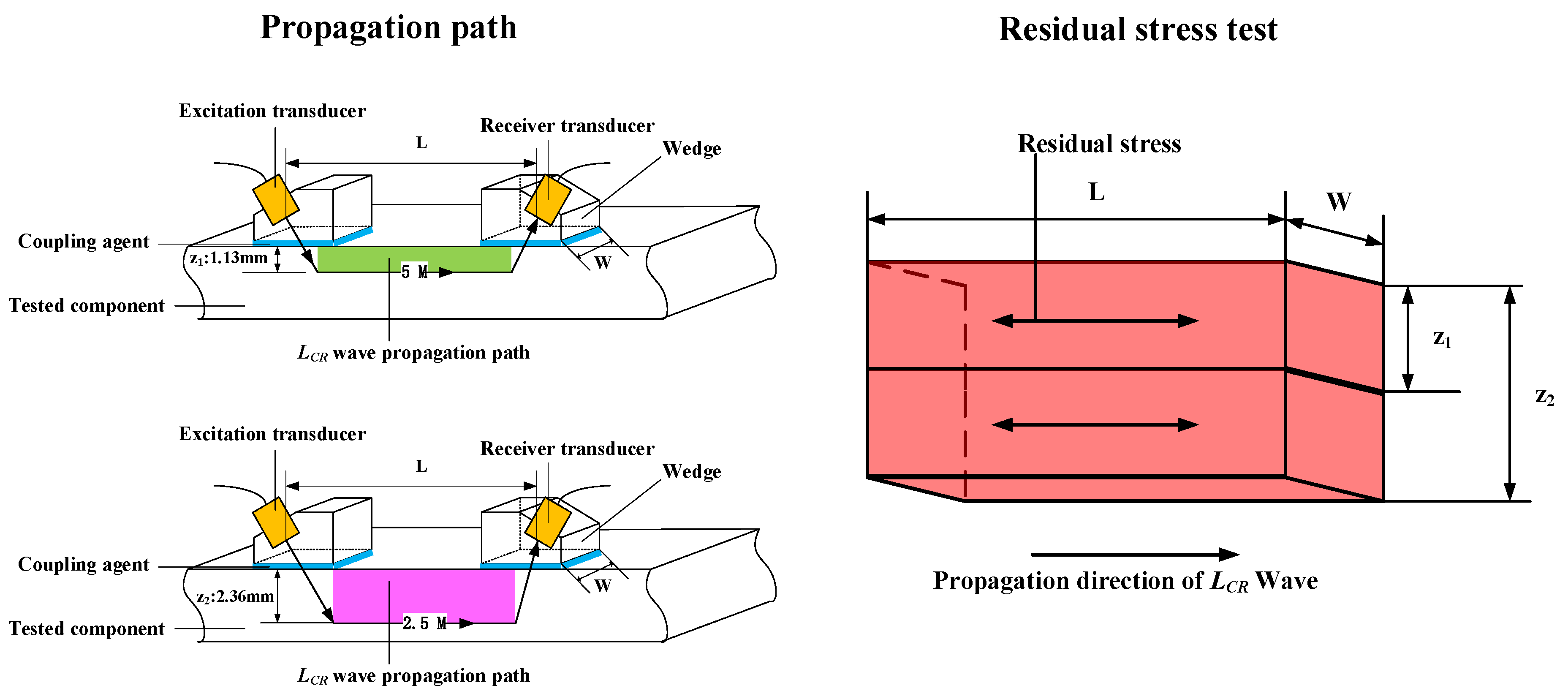
According to the principle of acoustic elasticity, the velocity of propagation sound is decreased by tensile residual stress and increased by compressive residual stress. By measuring the sound propagation time in the calibration area and the tested area, the measured stress can be achieved. In the actual test process, the measurement of residual stress at different depths can be achieved by changing the probe with different center frequencies. Liu et al. determined the relationship between the detection frequency and detection depth [
22], where, for aluminum alloy plates, 5 M probes can detect depths of 1.13 mm and 2.5 M probes can detect depths of 2.36 mm.
As shown in
Figure 1, under the condition when the distances between the excitation and receiver transducers (L), wedge width (W), and frequency (F) are fixed, the average three-dimensional stress in the range can be calculated. It can be approximated that the 5 M sound wave propagation through the area is seen as a small rectangle (green color), whereas the 2.5 M sound wave propagation through the area is seen as a large rectangle of equal length and width (pink color). Referring to the simplified model established by the study by Lu et al., the stresses detected by 5 M are as follows [
23]:
Similarly, the stresses detected by 2.5 M are:
2.2. Measuring Position and Instrument Description
The residual stress detector adopts the instrument developed by Beijing Institute of Technology, which brings the detection accuracy to within ±20 MPa. According to GB/T 32073-2015, tensile samples for the calibration of the stress coefficient K were produced. A WDW-200E microcomputer-controlled electronic universal testing machine was used to load the tensile specimens, and the tensile results show that the yield strength of 5A06/6061/7075 aluminum alloy is 135 MPa, 240 MPa, and 460 MPa, respectively.
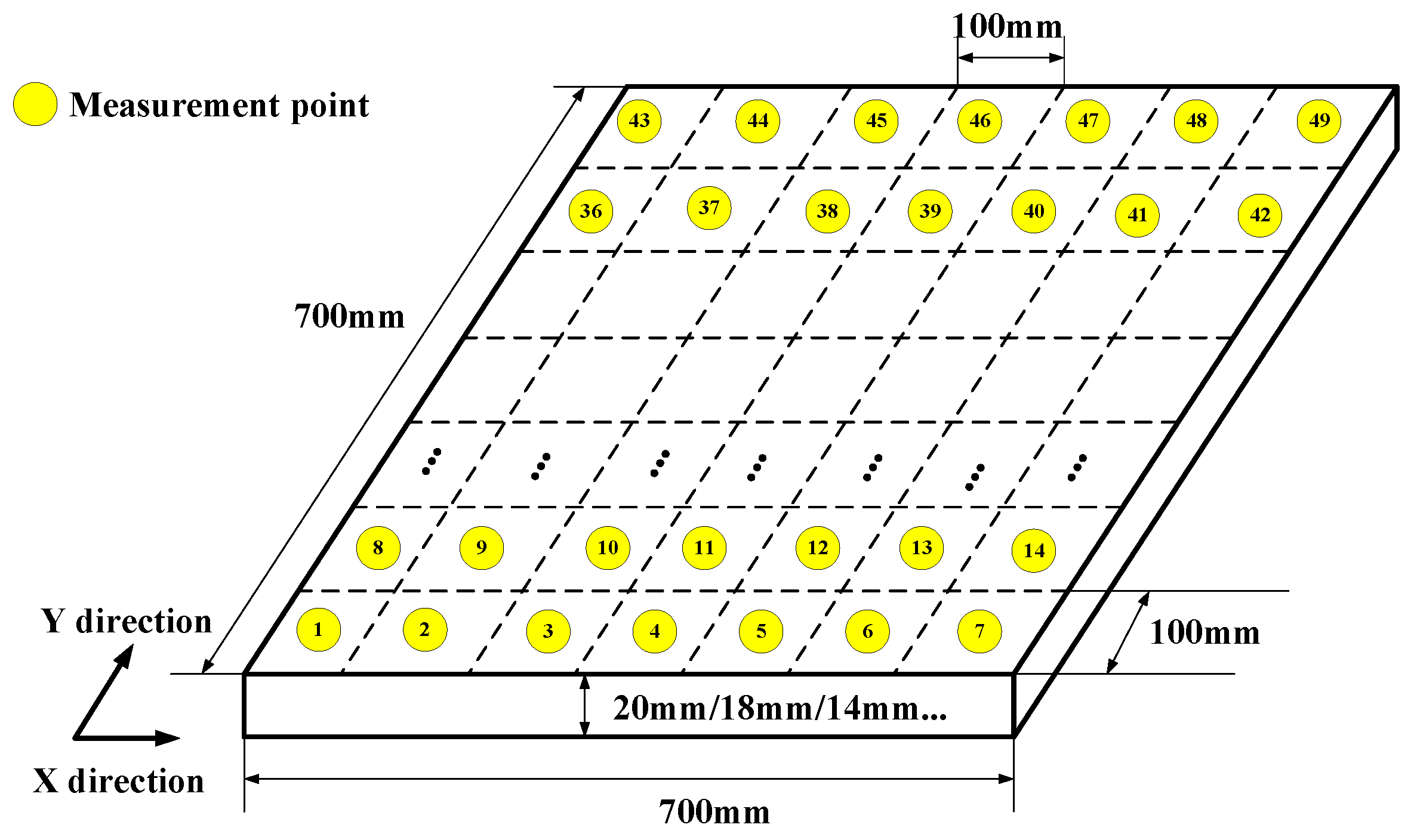
As shown in
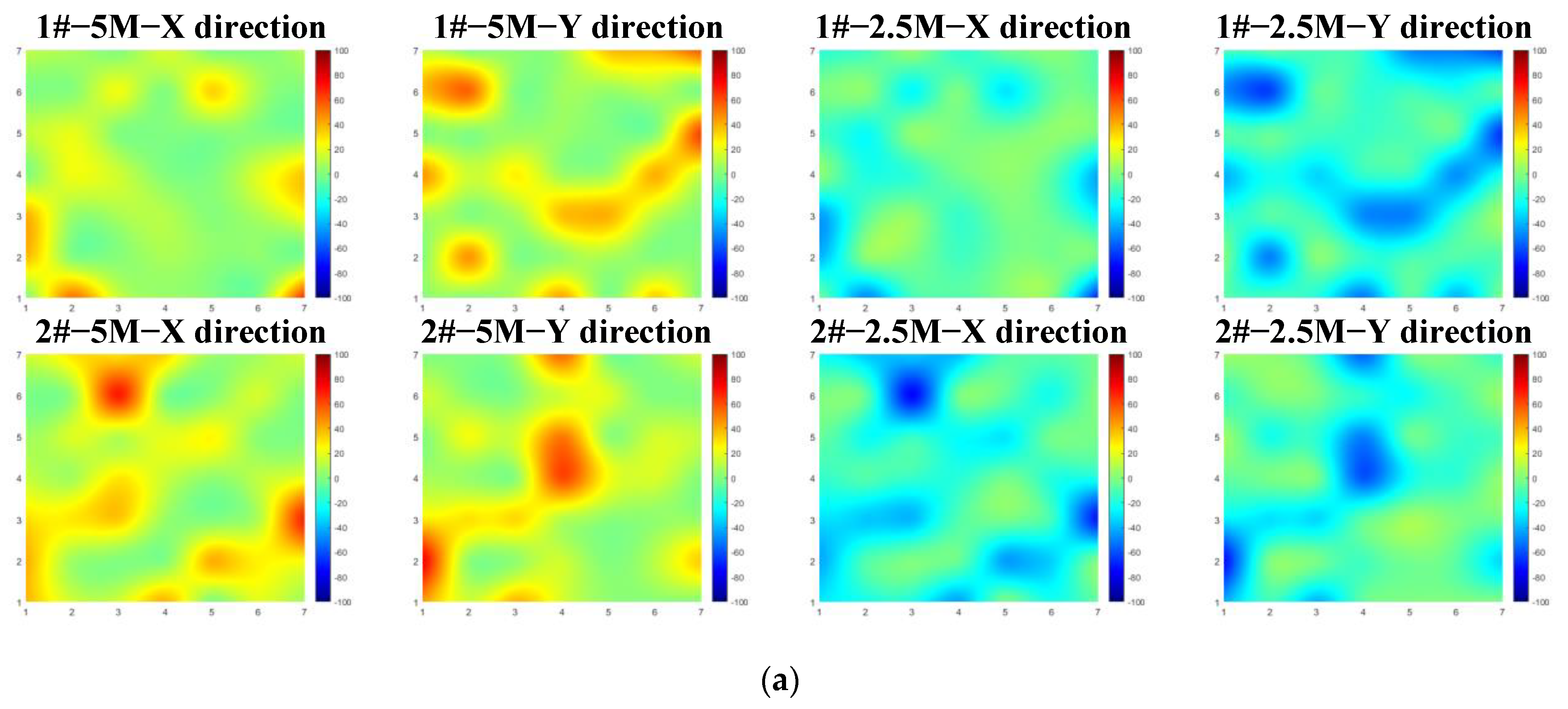
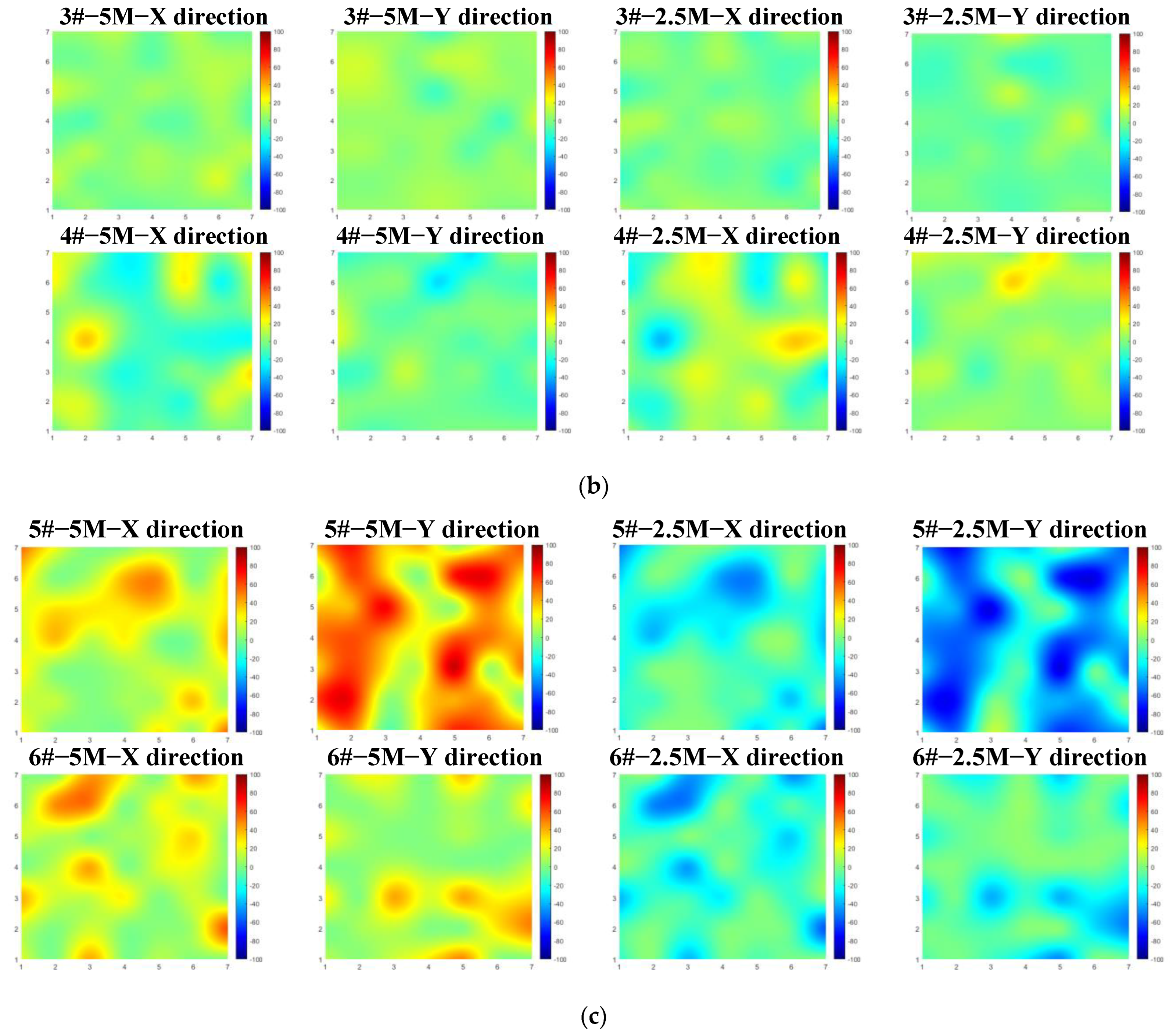
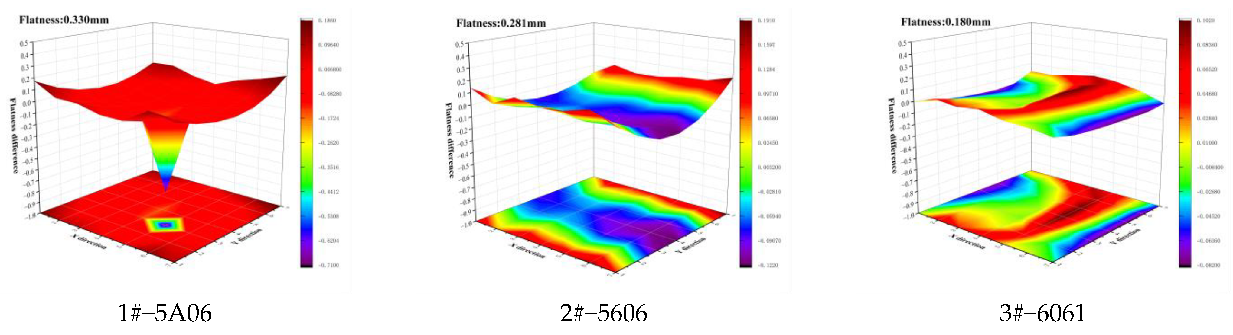
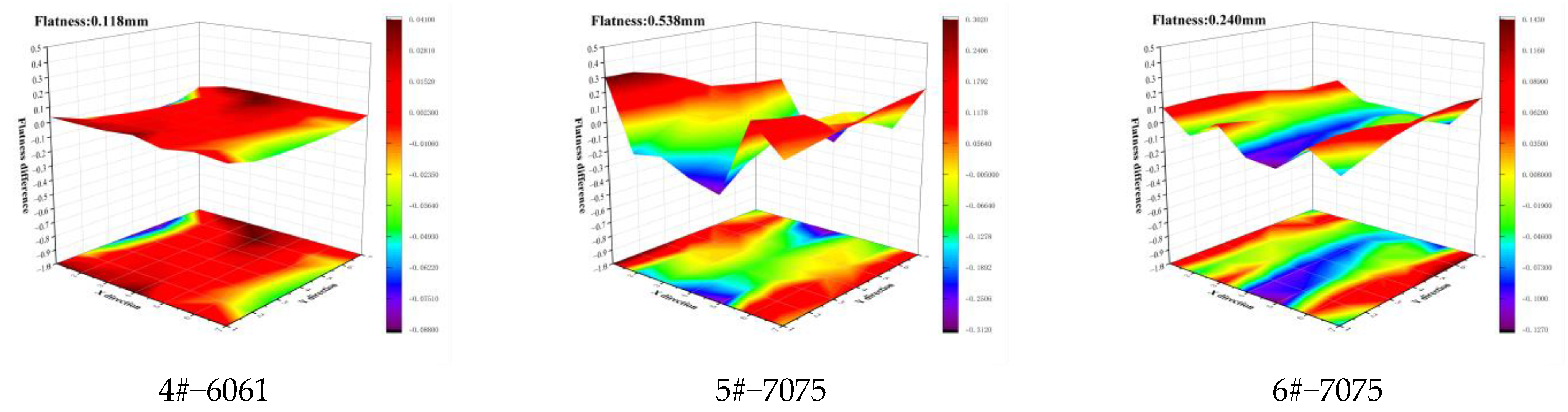
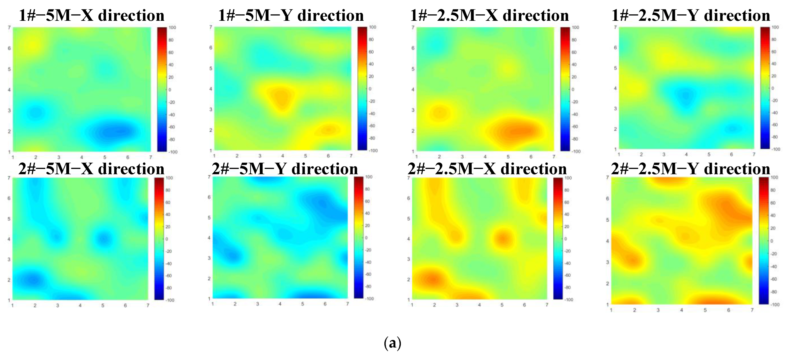
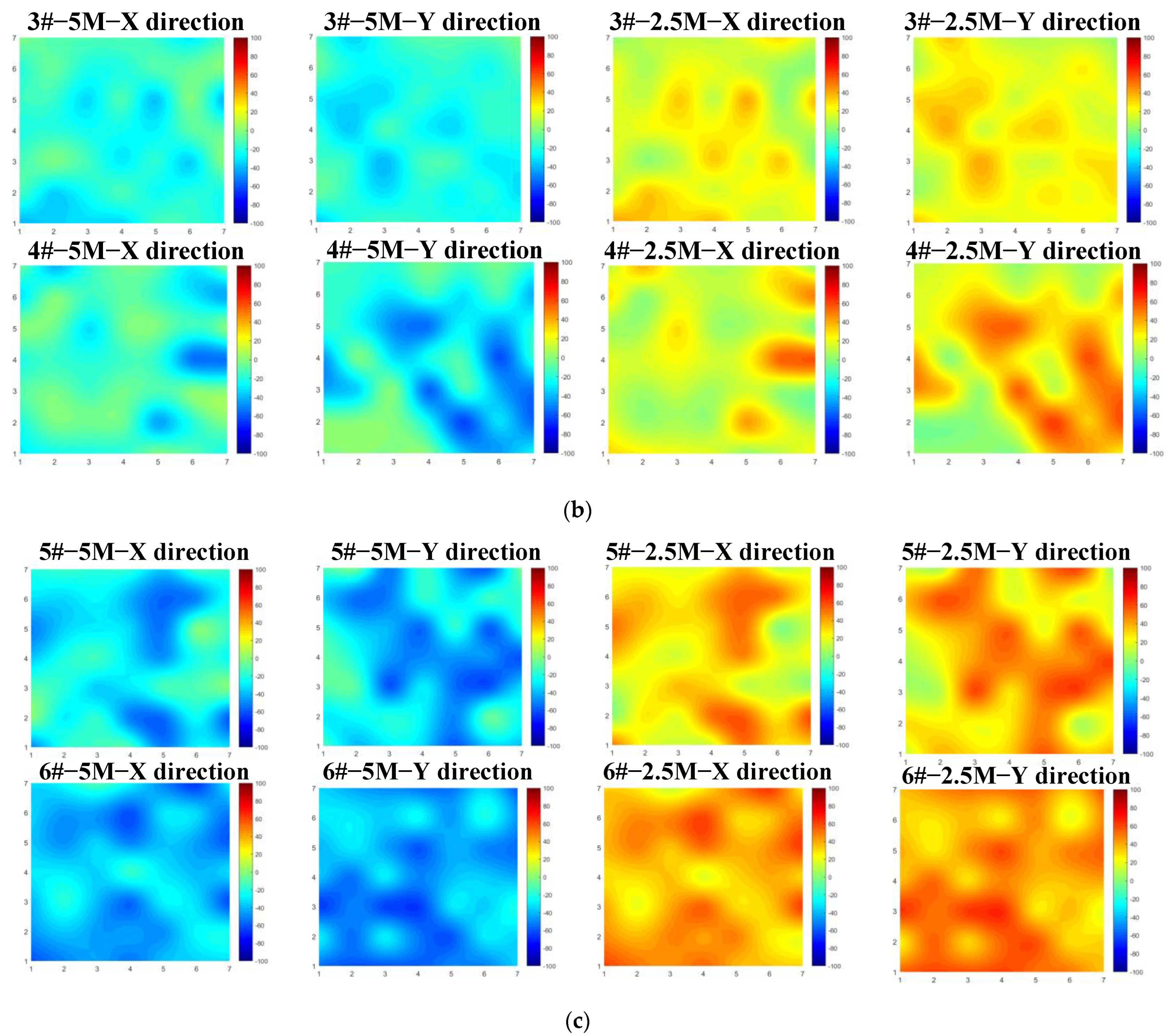
Figure 2, grids were divided and equally spaced on the surface of the plate, and residual stress was measured at the center of each grid. The rolling direction was set as the X direction and was perpendicular to the rolling direction, which was the Y direction. A total of 49 points were measured at each frequency. For quantitatively observing the flatness deformation of components after machining and stress reduction, a three-coordinate measurement is also required at the residual stress detection point to fit the flatness. The size measurement was carried out by the Global 9208 contact measuring instrument of Hexagon company.
2.3. Test Process and Parameters
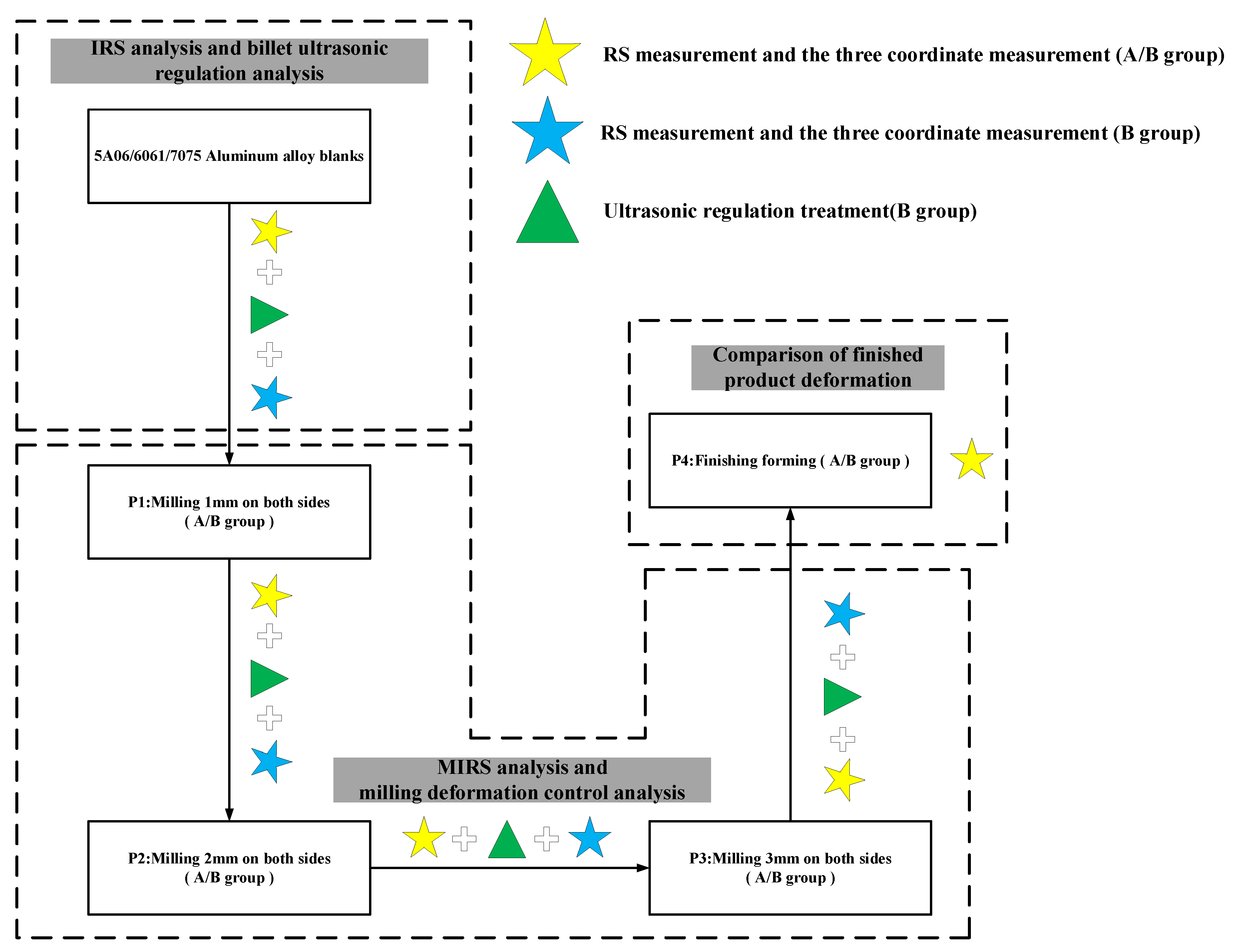
Referring to the existing processing of an aluminum alloy antenna, the ultrasonic stress relief method was introduced after blank and milling. The test process is shown in
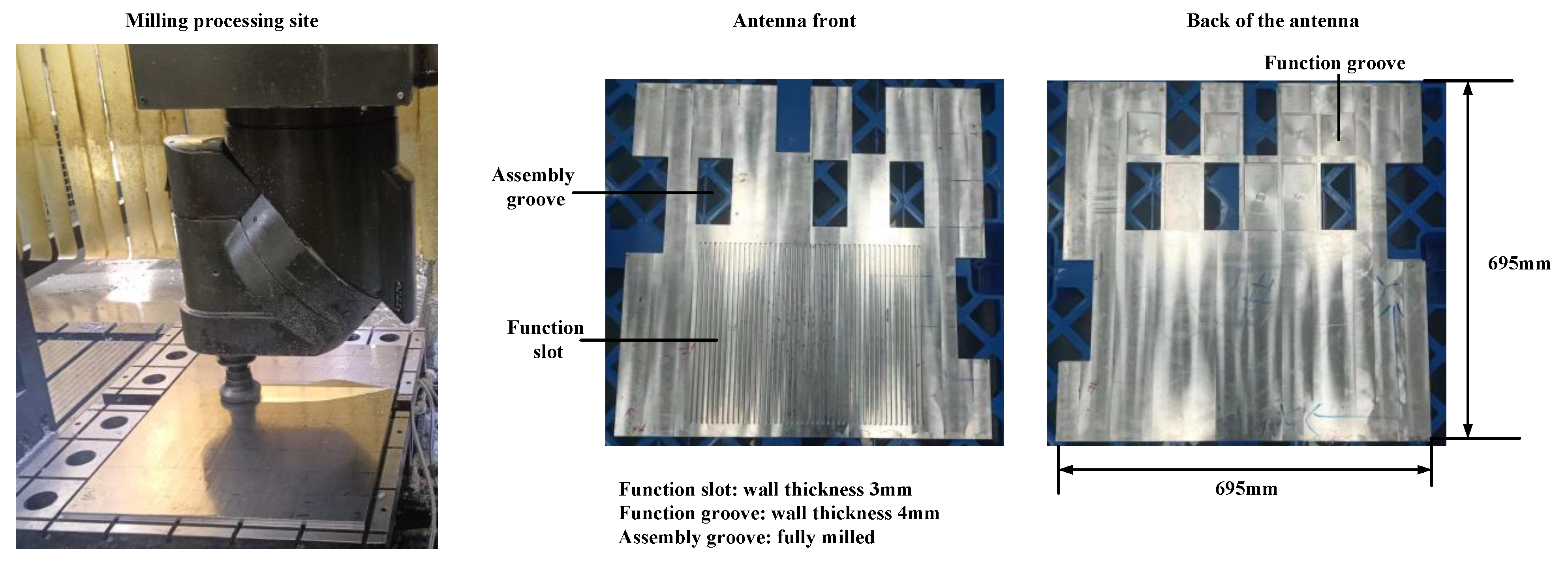
Figure 3. The initial blank thickness is 20 mm, and an 8 mm flat plate is formed after 1 mm, 2 mm, and 3 mm double-sided milling. Finally, the functional slot and assembly groove were processed on the front side of the flat plate, and the functional groove was formed on the back side. The finished product of the component is shown in
Figure 4.
Two pieces of 5A06/6061/7075 aluminum alloy blanks were selected for the experimental study. 1#/2# are 5A06 plates, 3#/4# are 6061 plates, and 5#/6 # are 7075 plates. The milling materials were divided into group A (1#/3#/5#) and group B (2#/4#/6#). Group A is the comparison group, which is only the milling aluminum alloy plate. Group B is the control group, and its processing flow is the same as that of group A. An ultrasonic stress relief method was used to eliminate residual stress in the blank stage and after milling.
The milling parameters and the mechanical properties of the materials are listed in
Table 1 and
Table 2, respectively. Note that, in contrast to conventional milling, where a smaller residual stress distribution is desirable, here, in order to compare the effects of ultrasonic stress relief methods on deformation control, a lower milling speed and rotational speed were selected, and the milling path used reciprocating milling to introduce larger residual stress and deformation after milling.
2.4. Ultrasonic Stress Relief Method
The residual stress elimination process is essentially the gradual release of elastic strain energy stored in the material through microscopic or local elastic deformation, i.e., related to the movement of dislocations. Dislocation motion can transform the elastic deformation associated with residual stress, partially or completely, into elasto-plastic deformation because of the lattice distortion (microplastic deformation) that occurs within the material at the microscopic level, resulting in residual stress distribution. The lattice distortion is caused, to a large extent, by dislocations. Stress release in aluminum alloys is mainly caused by the thermally activated motion of dislocations (slip, climb, dislocation reaction), which, in turn, generates microplastic deformation and induces stress release.
The principle of the ultrasonic method for reducing and homogenizing residual stress is to use the directionality of acoustic waves and the controllability of excitation energy to inject a high-energy elastic wave beam into the interior of the components in a specified direction, relying on the energy of the elastic wave to relax the binding force between and within the lattices and excite the dislocations to start moving.
When the distortion region in the crystal is excited to move by an external force, it is subjected to the resistance given by the lattice dot matrix; that is, to make the dislocation slide distance of
b (Burger vector), it is necessary to cross an energy barrier, which is called the
P-N potential barrier and can be expressed by (1) as follows:
Here, is the shear modulus, is the Poisson’s ratio, and is the dislocation half-width.
The maximum lattice resistance
P-N force for dislocation movement is:
where
a is the upper and lower atomic spacing of the two layers in the dislocation region. If the dislocation can overcome the lattice resistance and if the slide is considered as the yielding of the crystal, set
a ≈
b,
= 1/3. Calculate using Equation (4) to obtain
; that is, the
P-N force is equal to the actual yield stress.
Take a sufficiently small crystal mass in the ultrasound field with a volume of
, a pressure of
, a density of
, and a mass of
. When the volume of the crystal mass is changed from
to
by ultrasonic waves, the kinetic energy
and potential energy
of the mass are [
24]:
The dislocation can be opened when the energy of the high-intensity ultrasonic field acting on the dislocation is greater than . The residual stress due to lattice distortion on the microscopic level is released, which is manifested on the macroscopic level as a stress peak decrease and re-equilibrium distribution of overall stress. Finally, the goal of quantifying and controlling the residual stress in different directions inside the components can be achieved.
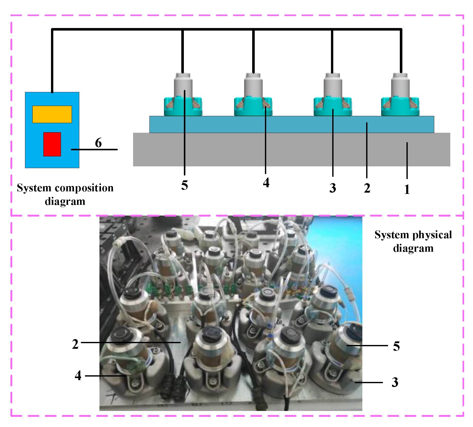
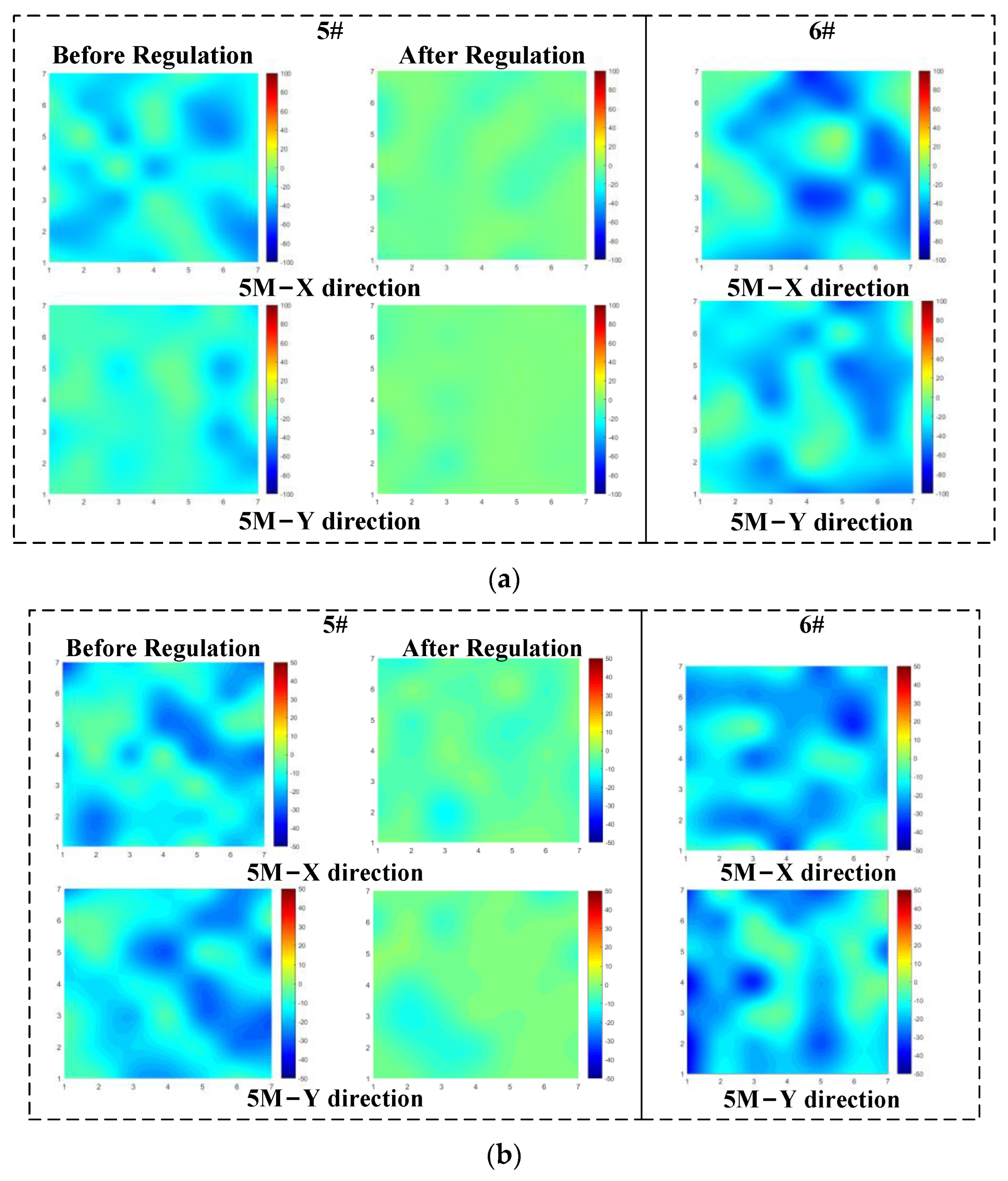
2.5. USR System
Since the antenna component is a large-sized flat-plate structure, end milling is gradually required during the milling process. An USR system was self-developed, as shown in
Figure 5. Firstly, an ultrasonic transducer was fixed at the node position by a fixed tooling and then combined with a vacuum suction cup so that the front end surface of the transducer is 1.5 mm higher than the bottom surface of the suction cup. Then, grease was applied. When the vacuum suction cup is placed on the regulated plane, the transducer moves upward so that the connecting spring on the fixing tooling is in a compressed state, thereby ensuring that the transducer front end is always closely attached to the plane. In the actual stress relief control, 16 sets of ultrasonic transducers were evenly arranged on the regulated plane. During the control process, the aluminum plate was placed in a constant-temperature air-conditioning room at 26 °C, and the piezoelectric ceramics were monitored by a laser thermometer, where the output amplitude of a single transducer is 10 µm (±2 µm). The transducer piezoelectric ceramic temperature increases with an increase in the working time. In order to ensure that the output power is not less than 60 W, the single processing time should not exceed 20 min in order to prevent the output power shortage caused by the high temperature of the piezoelectric ceramic. The regulation parameters are shown in
Table 3.
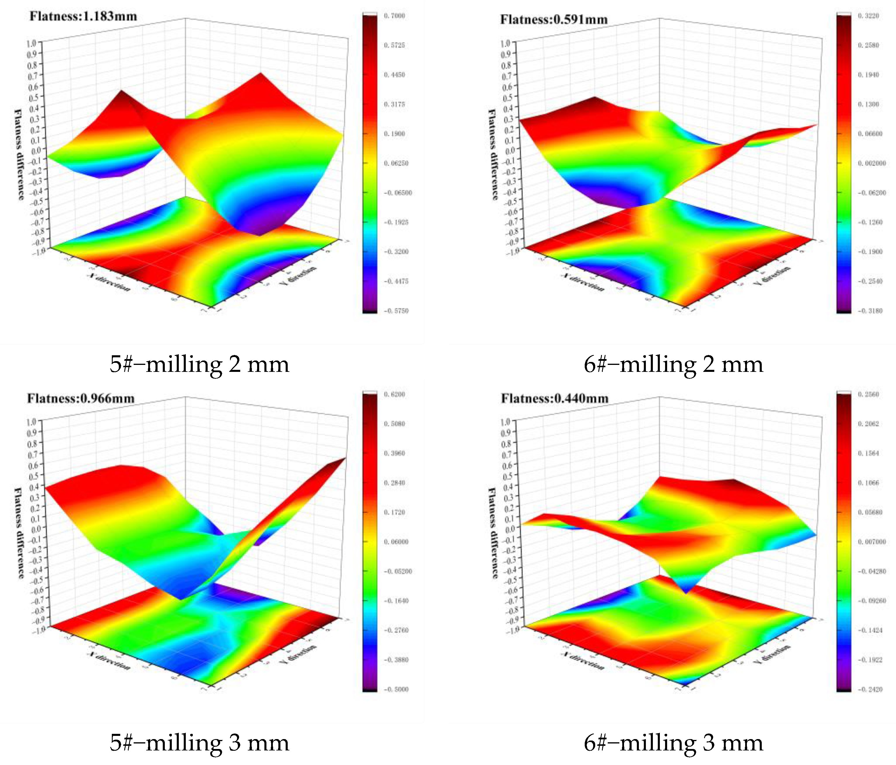
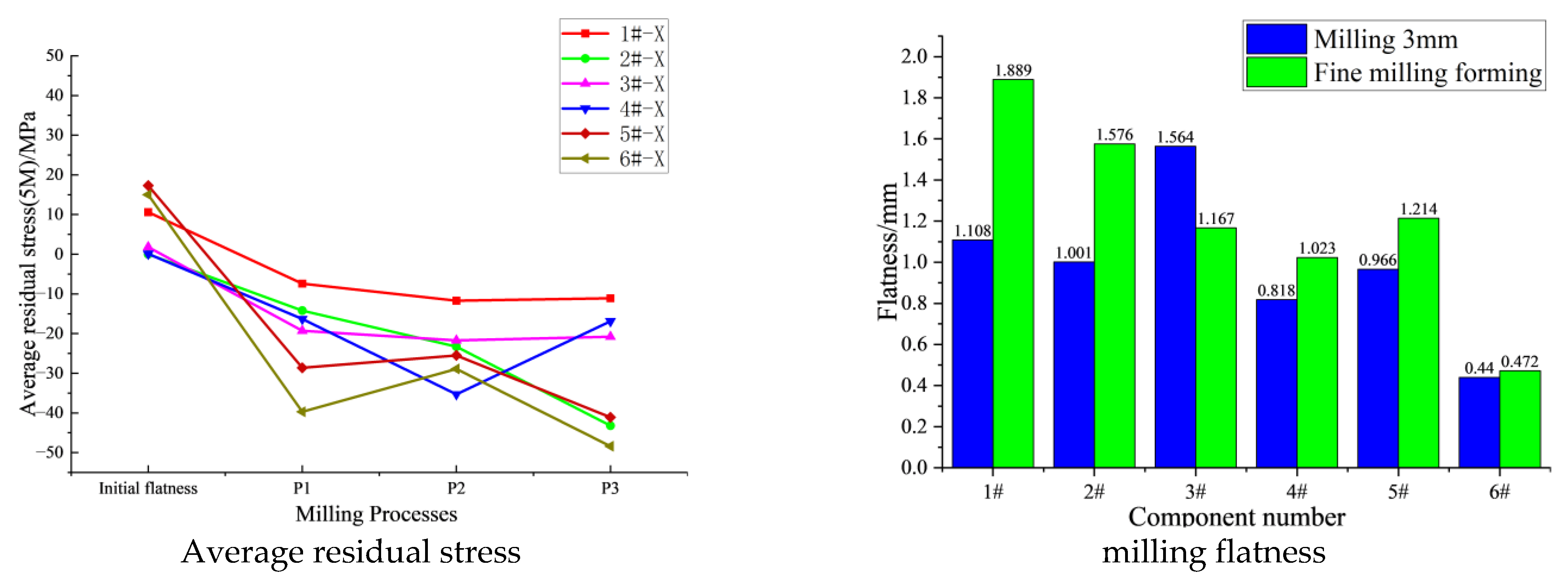
4. Conclusions
In view of the problem of the flatness of aluminum alloy thin-walled components being difficult to guarantee after forming, this paper used the ultrasonic critical refraction longitudinal wave method to detect the residual stresses in the 5A06/6061/7075 blanks and milling processing procedures of the antenna components, and analyzed the deformation of the component combined with three coordinate measuring instruments. Then, a self-developed USR system was used to remove the stress of the aluminum alloy plate in the blank stage, unilateral milling 1 mm, unilateral milling 2 mm, and unilateral milling 3 mm, respectively, to verify the effect of the ultrasonic stress relief method. The effects of the ultrasonic stress relief process on the deformation control of a thin-walled antenna were studied by comparing the milling deformation effects of two aluminum alloy plates under different stress states. The conclusions are as follows:
(1) The residual stress distribution of an aluminum alloy blank along the depth direction is in the form of a stretching–compression oscillating distribution. The residual stress distributions along the rolling direction and perpendicular to the rolling direction are not the same, but the stress level is similar. There are irregularly distributed stress concentration areas on all slab blanks. The surface of the milled aluminum alloy plate shows compressive residual stress distribution and the near surface shows almost symmetrical tensile residual stress.
(2) With small geometric deformation, ultrasonic stress relief treatment can quickly and significantly reduce the residual stress peak and stress concentration area in aluminum alloy, homogenize the overall residual stress distribution, and reduce the stress difference of the plate along the surface at different depths. Milling after controlling the initial residual stress can effectively reduce the milling deformation. Then, after milling, the residual stress of milling is removed by the USR system, which can gradually control the flatness deformation of the aluminum alloy plate, and finally make it have lower flatness deformation after forming. Soon after, the combination of process parameter optimization and clamping method optimization makes it possible to promote the application of ultrasonic stress relief technology in the milling forming of thin-walled components.


