
A Compact Electromagnetic Dual Actuation Positioning System with a 10 mm Range and Nanometer Resolution
Abstract
:1. Introduction
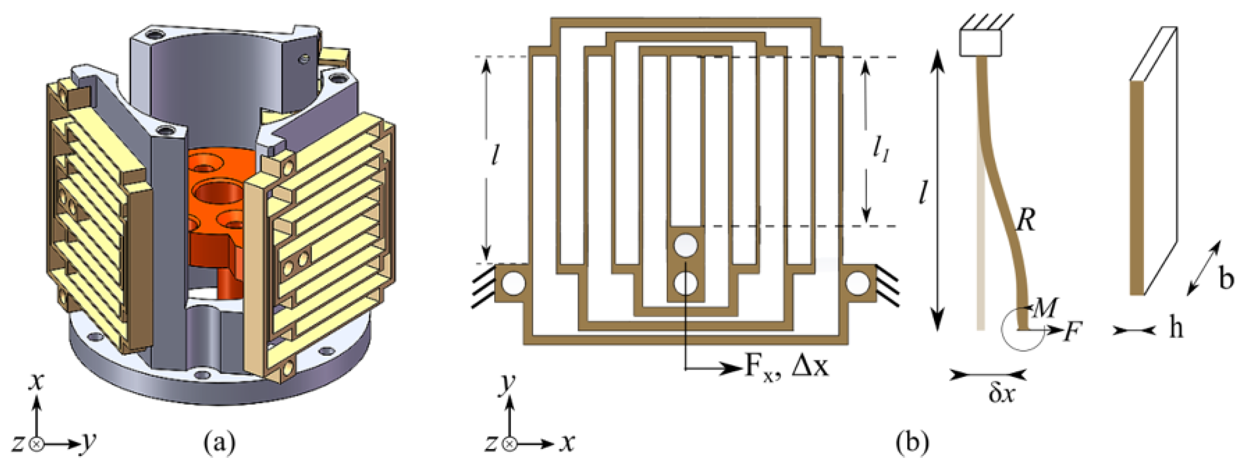
2. Mechanical and Actuator Design
2.1. Design of the Flexure Mechanism
2.2. Design of the Macro Coil
2.3. Addressing the Limitation of Positioning with the Macro Coil
2.4. Design of the Micro Coil
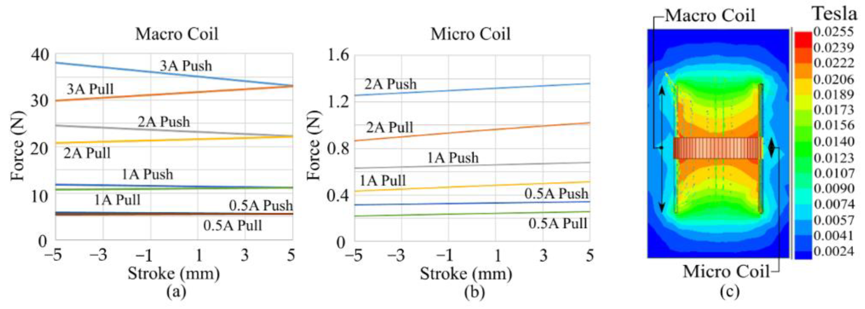
2.5. Electromagnetic Force Simulation for the Coils
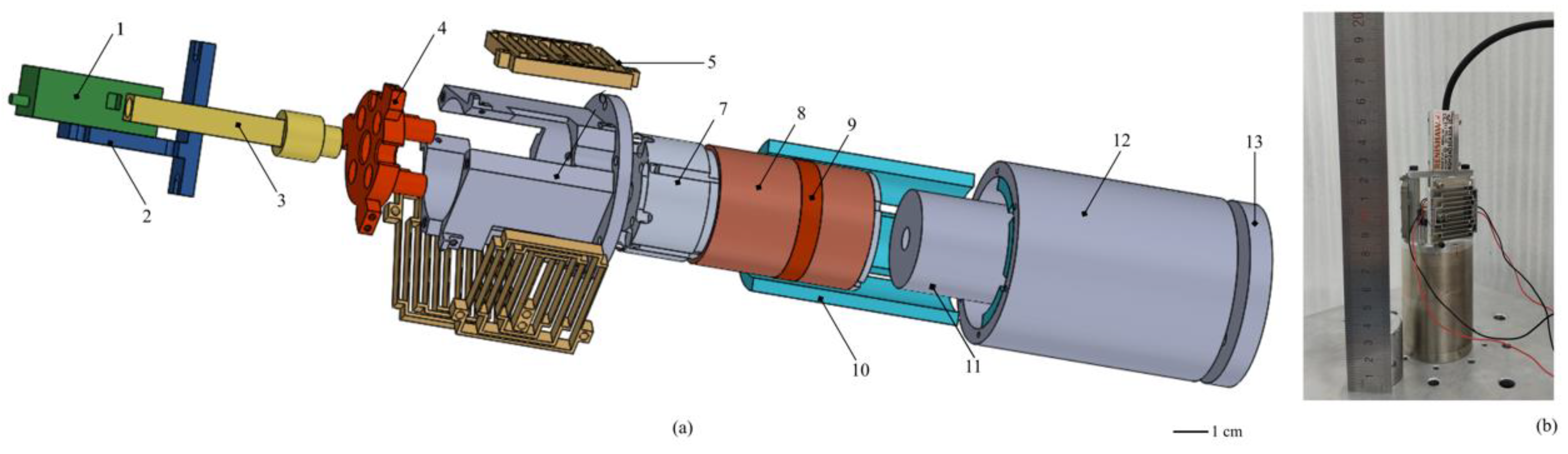
2.6. Assembly
3. Electrical Parameters of the Coils, Current Drive Non-Linearities, Actual Force Constants and Controller
3.1. Electrical Parameters of the Coils
3.2. Current Drive
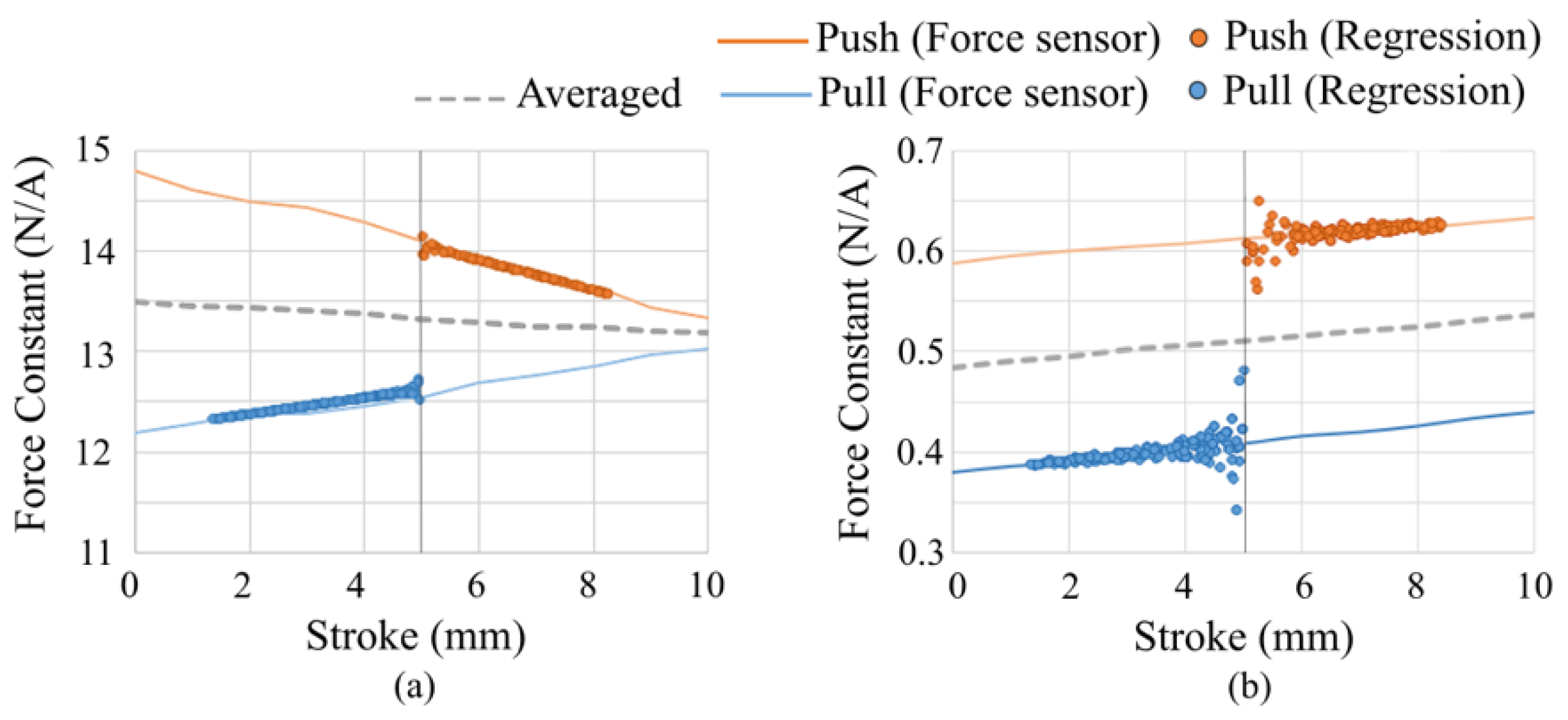
3.3. Force Constant
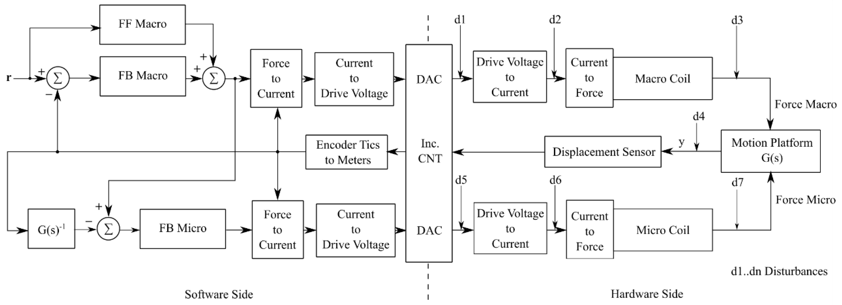
3.4. Controller
4. Experimental Results
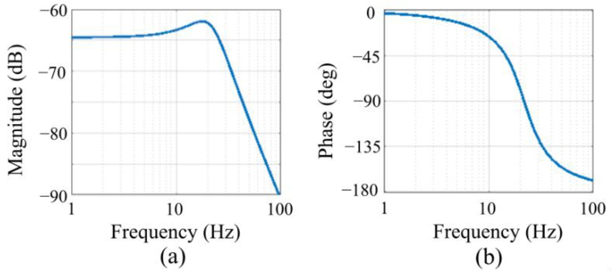
4.1. System Identification
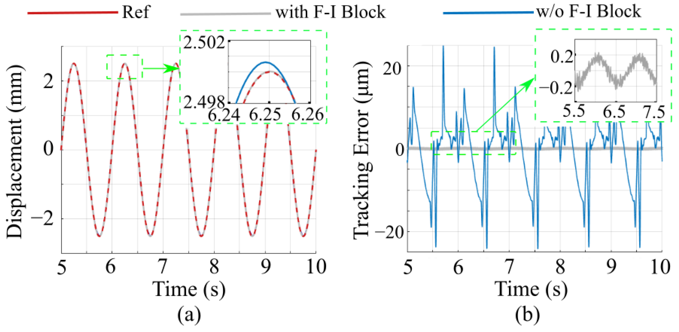
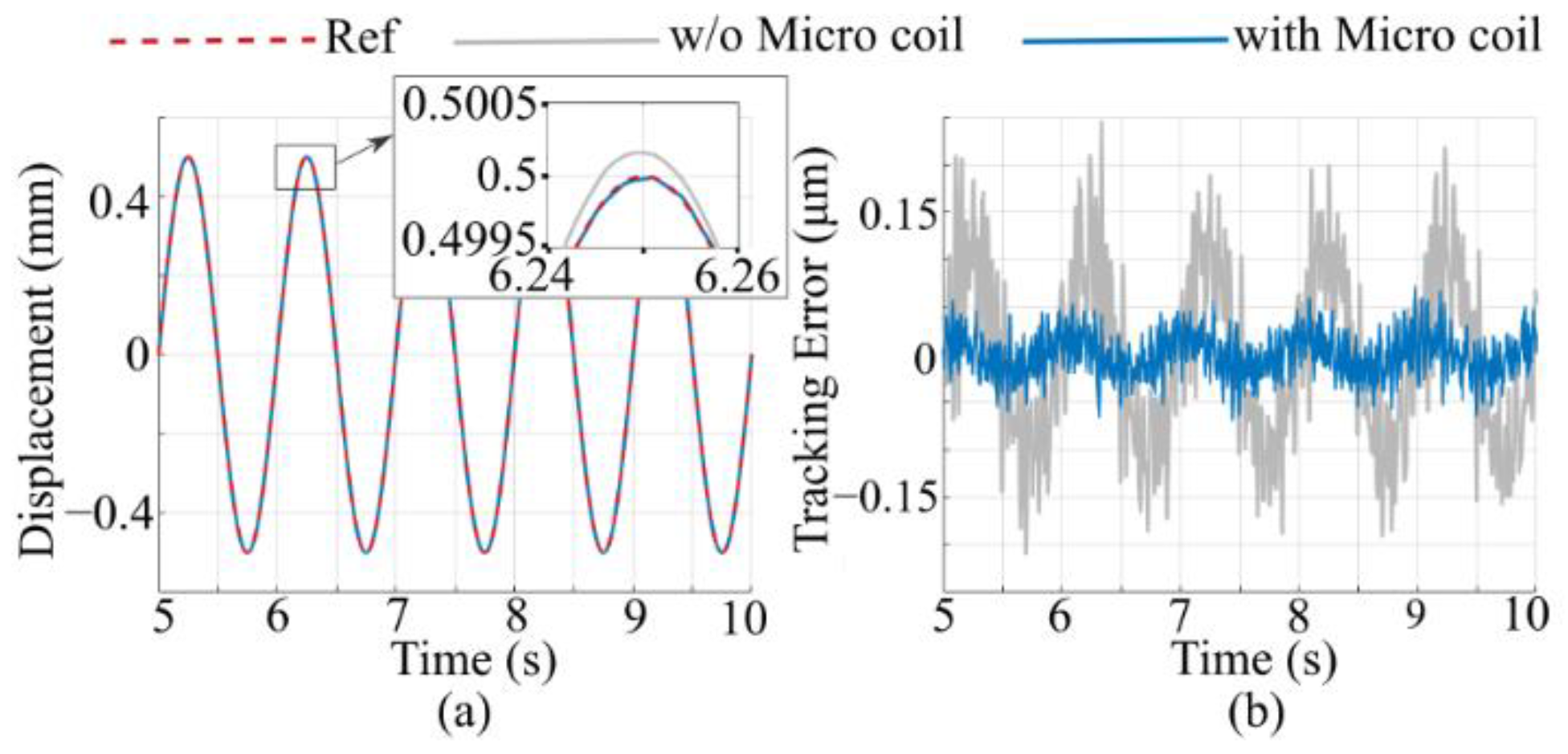
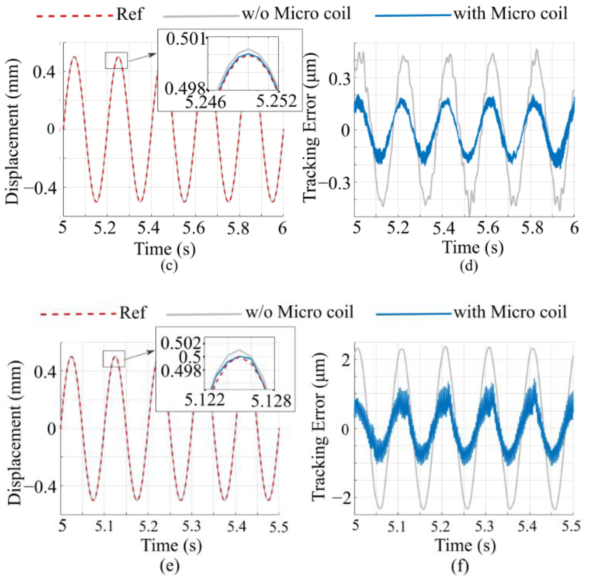
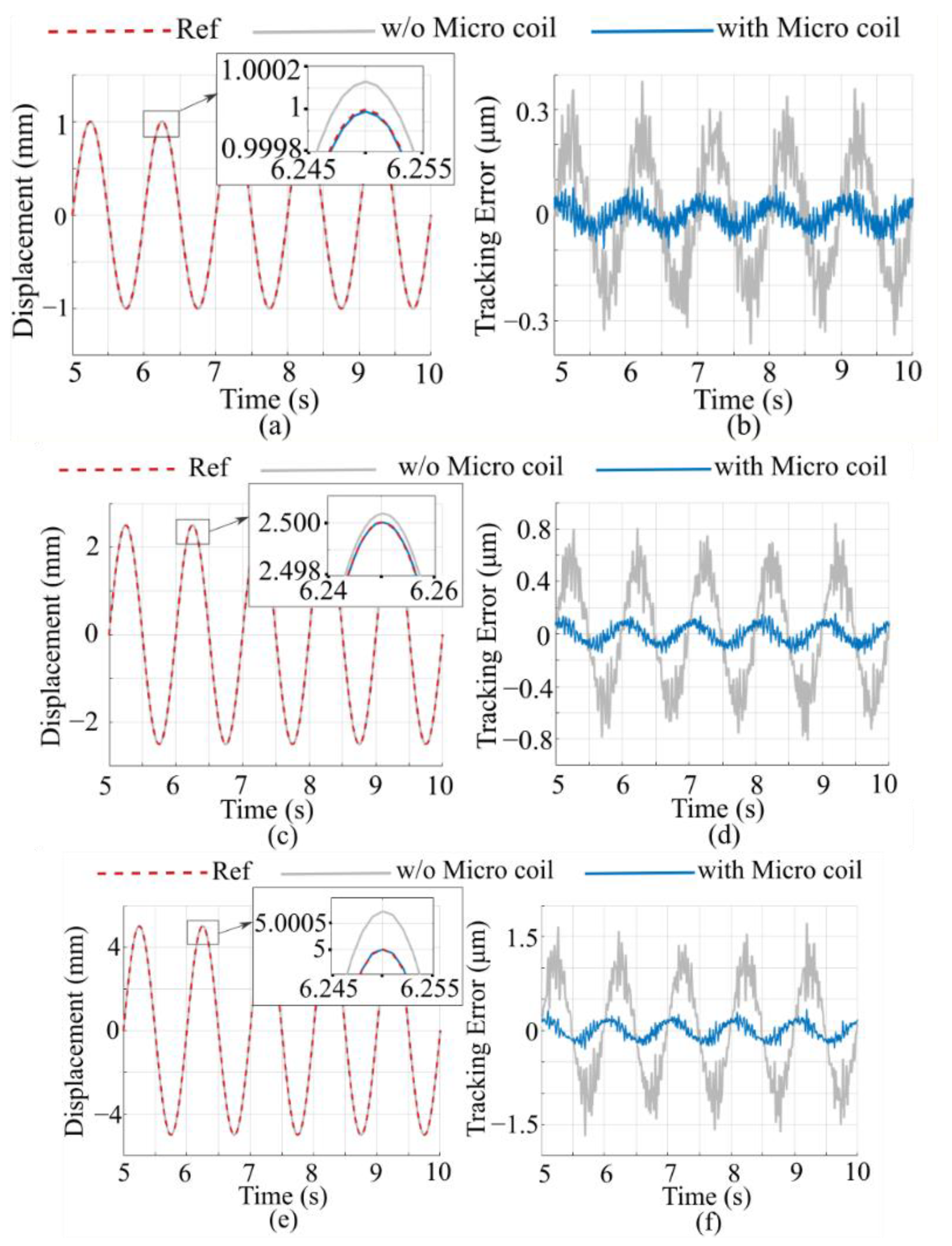
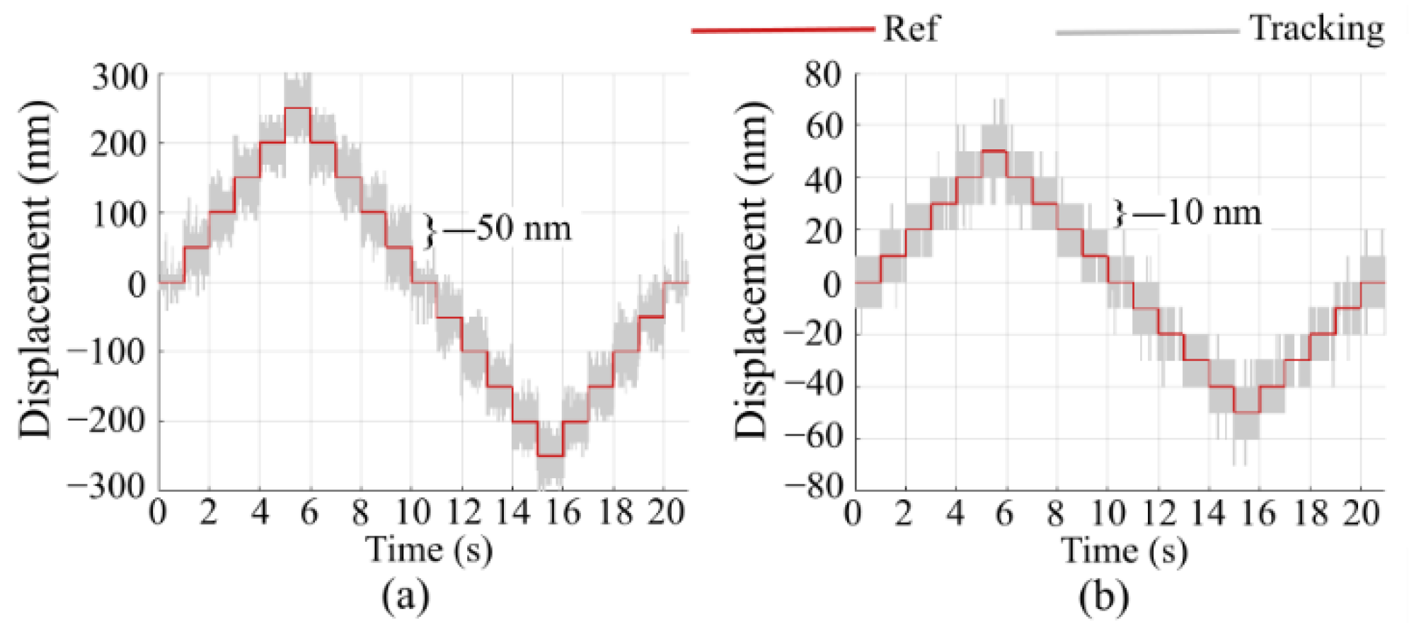
4.2. Tracking of Sinusoidal Reference
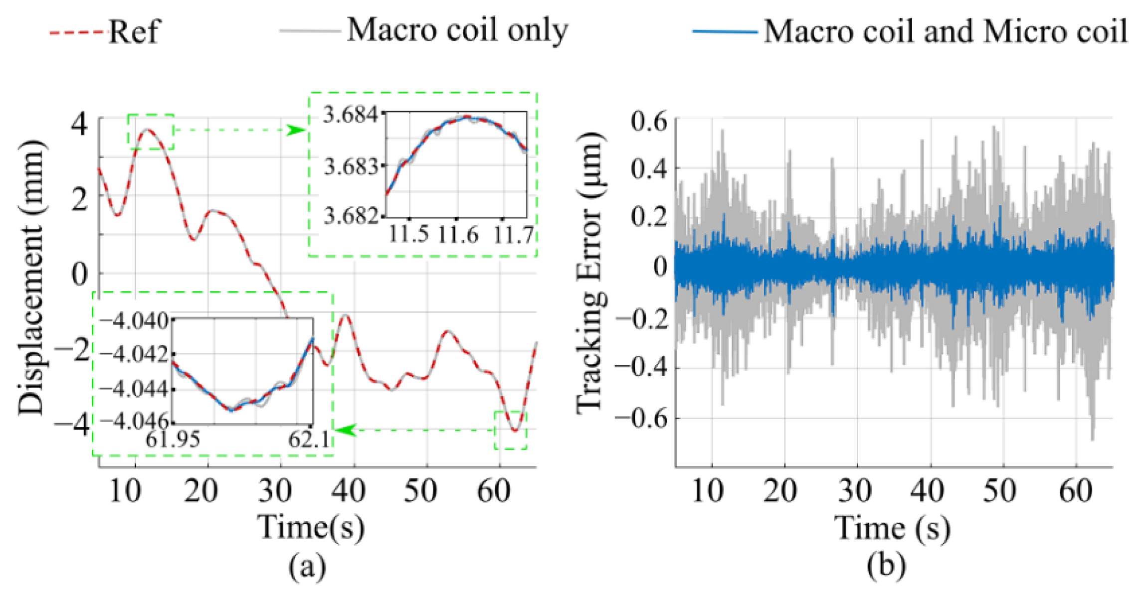
4.3. Random Path Tracking
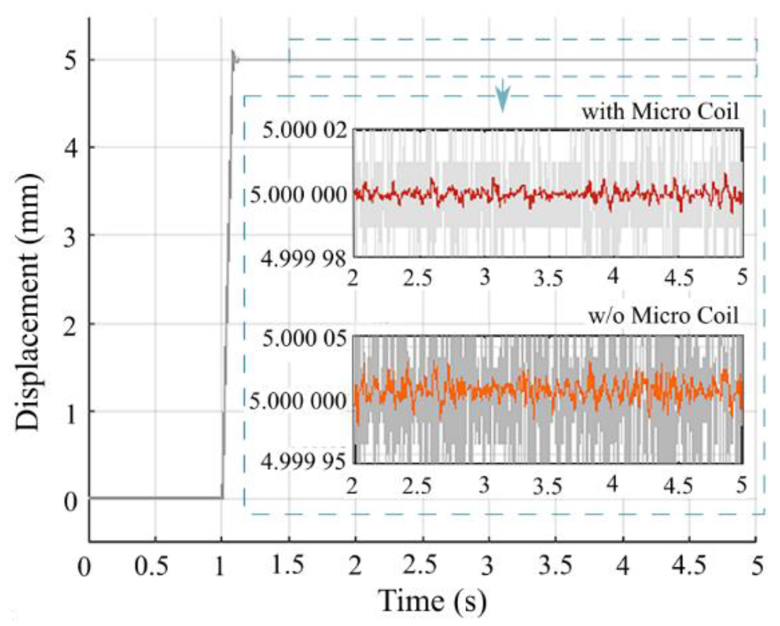
4.4. Step Response
4.5. Resolution
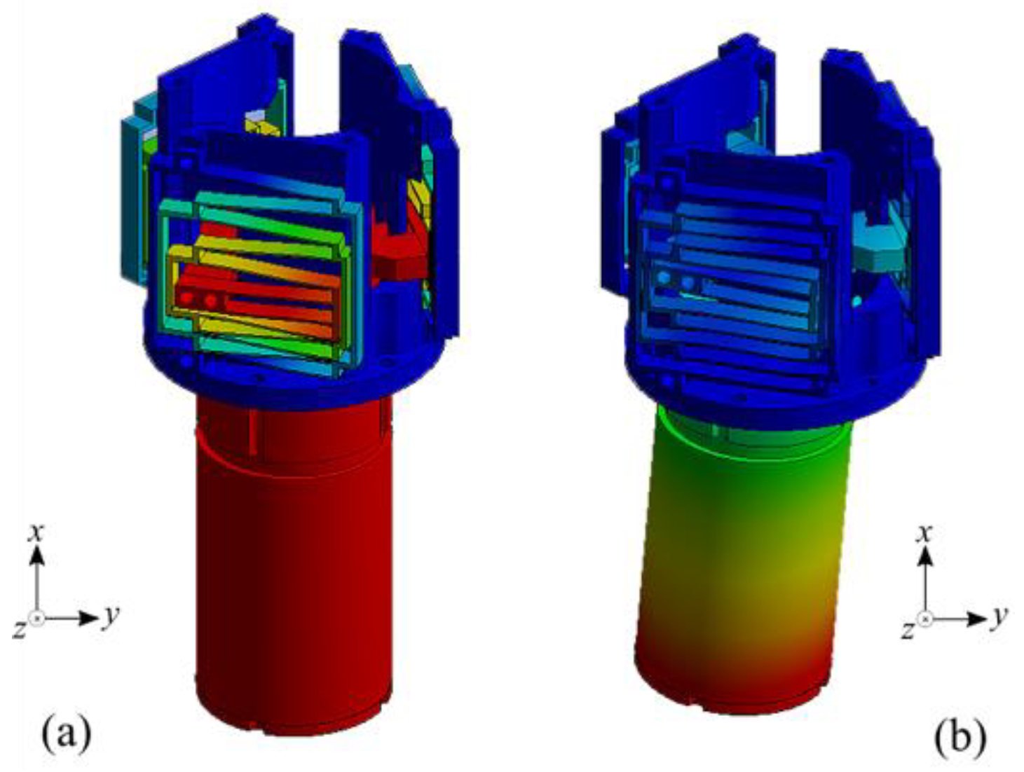
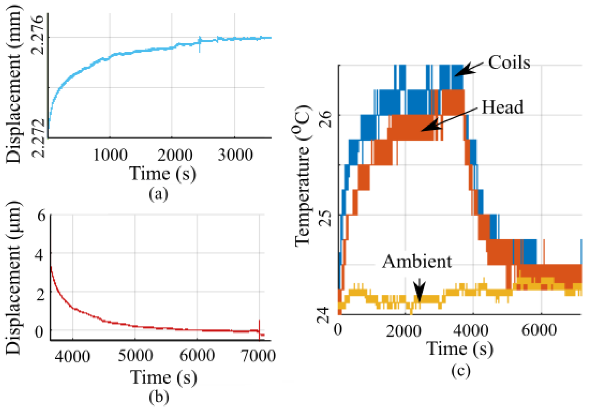
4.6. Thermal Analysis
5. Discussion and Comparison with Other Works
5.1. Discussion of the Results
5.2. Comparison with Other Works
6. Conclusions
Author Contributions
Funding
Data Availability Statement
Conflicts of Interest
References
- Teo, T.J.; Bui, V.P.; Yang, G.; Chen, I.-M. Millimeters-Stroke Nanopositioning Actuator with High Positioning and Thermal Stability. IEEE/ASME Trans. Mechatron. 2015, 20, 2813–2823. [Google Scholar] [CrossRef]
- Shan, G.; Li, Y.; Zhang, L.; Wang, Z.; Zhang, Y.; Qian, J. Contributed Review: Application of Voice Coil Motors in High-Precision Positioning Stages with Large Travel Ranges. Rev. Sci. Instrum. 2015, 86, 101501. [Google Scholar] [CrossRef]
- Hiemstra, D.B.; Parmar, G.; Awtar, S. Performance Tradeoffs Posed by Moving Magnet Actuators in Flexure-Based Nanopositioning. IEEE/ASME Trans. Mechatron. 2014, 19, 201–212. [Google Scholar] [CrossRef]
- Devasia, S.; Eleftheriou, E.; Moheimani, S.R. A Survey of Control Issues in Nanopositioning. IEEE Trans. Control Syst. Technol. 2007, 15, 802–823. [Google Scholar] [CrossRef]
- Makarovic, J. Lightweight Positioning: Design and Optimization of an Actuator with Two Controlled Degrees of Freedom; Citeseer: Princeton, NJ, USA, 2006. [Google Scholar] [CrossRef]
- Christiansen, B.; Maurer, H.; Zirn, O. Optimal Control of a Voice-Coil-Motor with Coulombic Friction. In Proceedings of the 2008 47th IEEE Conference on Decision and Control, Cancun, Mexico, 9–11 December 2008; pp. 1557–1562. [Google Scholar]
- Lin, C.-J.; Yau, H.-T.; Tian, Y.-C. Identification and Compensation of Nonlinear Friction Characteristics and Precision Control for a Linear Motor Stage. IEEE/ASME Trans. Mechatron. 2012, 18, 1385–1396. [Google Scholar] [CrossRef]
- Takrouri, M.; Dhaouadi, R. ADALINE-Based Friction Identification of a Linear Voice Coil DC Motor. In Proceedings of the 2016 American Control Conference (ACC), Boston, MA, USA, 6–8 July 2016; pp. 3062–3068. [Google Scholar] [CrossRef]
- Butt, H.U.; Waleed, D.; Dhaouadi, R. Friction Estimation of a Linear Voice Coil Motor Using Robust State Space Sinusoidal Reference Tracking. In Proceedings of the 2018 11th International Symposium on Mechatronics and Its Applications (ISMA), Sharjah, United Arab Emirates, 4–6 March 2018; pp. 1–6. [Google Scholar] [CrossRef]
- Kim, W.; Trumper, D.L.; Lang, J.H. Modeling and Vector Control of Planar Magnetic Levitator. IEEE Trans. Ind. Appl. 1998, 34, 1254–1262. [Google Scholar] [CrossRef]
- Choi, Y.-M.; Gweon, D.-G. A High-Precision Dual-Servo Stage Using Halbach Linear Active Magnetic Bearings. IEEE/ASME Trans. Mechatron. 2011, 16, 925–931. [Google Scholar] [CrossRef]
- Zhu, H.; Teo, T.J.; Pang, C.K. Magnetically Levitated Parallel Actuated Dual-Stage (Maglev-PAD) System for Six-Axis Precision Positioning. IEEE/ASME Trans. Mechatron. 2019, 24, 1829–1838. [Google Scholar] [CrossRef]
- Gao, Q.; Chen, W.; Lu, L.; Huo, D.; Cheng, K. Aerostatic Bearings Design and Analysis with the Application to Precision Engineering: State-of-the-Art and Future Perspectives. Tribol. Int. 2019, 135, 1–17. [Google Scholar] [CrossRef]
- Tan, K.K.; Huang, S.; Liang, W.; Al Mamun, A.; Koh, E.K.; Zhou, H. Development of a Spherical Air Bearing Positioning System. IEEE Trans. Ind. Electron. 2011, 59, 3501–3509. [Google Scholar] [CrossRef]
- Howell, L.L. Compliant Mechanisms. In 21st Century Kinematics; Springer: Berlin/Heidelberg, Germany, 2013; pp. 189–216. [Google Scholar]
- Teo, T.J.; Chen, I.-M.; Yang, G.; Lin, W. Magnetic Field Modeling of a Dual-Magnet Configuration. J. Appl. Phys. 2007, 102, 074924. [Google Scholar] [CrossRef]
- Zhu, H.; Teo, T.J.; Pang, C.K. Analytical Model-Based Multiphysics Optimization of a Nanopositioning Electromagnetic Actuator. IEEE Trans. Ind. Electron. 2018, 65, 478–487. [Google Scholar] [CrossRef]
- Leung, C.; Lu, Z.; Esfandiari, N.; Casper, R.F.; Sun, Y. Automated Sperm Immobilization for Intracytoplasmic Sperm Injection. IEEE Trans. Biomed. Eng. 2010, 58, 935–942. [Google Scholar] [CrossRef] [PubMed] [Green Version]
- Hey, J.; Teo, T.J.; Bui, V.P.; Yang, G.; Martinez-Botas, R. Electromagnetic Actuator Design Analysis Using a Two-Stage Optimization Method with Coarse–Fine Model Output Space Mapping. IEEE Trans. Ind. Electron. 2014, 61, 5453–5464. [Google Scholar] [CrossRef]
- Probst, M.; Fluckiger, M.; Pané, S.; Ergeneman, O.; Nagy, Z.; Nelson, B.J. Manufacturing of a Hybrid Acoustic Transmitter Using an Advanced Microassembly System. IEEE Trans. Ind. Electron. 2009, 56, 2657–2666. [Google Scholar] [CrossRef]
- Yang, M.; Zhang, C.; Huang, X.; Chen, S.-L.; Yang, G. A Long Stroke Nanopositioning Stage with Annular Flexure Guides. IEEE/ASME Trans. Mechatron. 2021, 27, 1570–1581. [Google Scholar] [CrossRef]
- Mori, K.; Munemoto, T.; Otsuki, H.; Yamaguchi, Y.; Akagi, K. A Dual-Stage Magnetic Disk Drive Actuator Using a Piezoelectric Device for a High Track Density. IEEE Trans. Magn. 1991, 27, 5298–5300. [Google Scholar] [CrossRef]
- Chan, K.W.; Liao, W. Precision Positioning of Hard Disk Drives Using Piezoelectric Actuators with Passive Damping. In Proceedings of the 2006 IEEE International Conference on Mechatronics and Automation, Luoyang, China, 25–28 June 2006; pp. 1269–1274. [Google Scholar] [CrossRef]
- Liu, Y.-T.; Fung, R.-F.; Wang, C.-C. Precision Position Control Using Combined Piezo-VCM Actuators. Precis. Eng. 2005, 29, 411–422. [Google Scholar] [CrossRef]
- Dong, W.; Tang, J.; ElDeeb, Y. Design of a Linear-Motion Dual-Stage Actuation System for Precision Control. Smart Mater. Struct. 2009, 18, 095035. [Google Scholar] [CrossRef]
- Xu, Q. Design and Development of a Flexure-Based Dual-Stage Nanopositioning System with Minimum Interference Behavior. IEEE Trans. Autom. Sci. Eng. 2012, 9, 554–563. [Google Scholar] [CrossRef]
- Ito, S.; Steininger, J.; Schitter, G. Low-Stiffness Dual Stage Actuator for Long Rage Positioning with Nanometer Resolution. Mechatronics 2015, 29, 46–56. [Google Scholar] [CrossRef]
- Jiang, Y.; Zhu, Y.; Yang, K.; Hu, C.; Yu, D. A Data-Driven Iterative Decoupling Feedforward Control Strategy with Application to an Ultraprecision Motion Stage. IEEE Trans. Ind. Electron. 2014, 62, 620–627. [Google Scholar] [CrossRef]
- Gu, G.-Y.; Zhu, L.-M.; Su, C.-Y.; Ding, H.; Fatikow, S. Modeling and Control of Piezo-Actuated Nanopositioning Stages: A Survey. IEEE Trans. Autom. Sci. Eng. 2014, 13, 313–332. [Google Scholar] [CrossRef]
- Shinno, H.; Hashizume, H. High Speed Nanometer Positioning Using a Hybrid Linear Motor. CIRP Ann. 2001, 50, 243–246. [Google Scholar] [CrossRef]
- Seki, K.; Shinohara, Y.; Iwasaki, M.; Chinda, H.; Takahashi, M. Force Controller Design Based on PQ Method for Dual-Stage Actuators in Polishing Machines. In Proceedings of the IECON 2011-37th Annual Conference of the IEEE Industrial Electronics Society, Melbourne, Australia, 7–10 November 2011; pp. 3388–3393. [Google Scholar] [CrossRef]
- Cheung, N.C.; Cheung, B.M. Modelling and Control of a High Speed, Long Travel, Dual Voice Coil Actuator. In Proceedings of the Second International Conference on Power Electronics and Drive Systems, Singapore, 26–29 May 1997; Volume 1, pp. 270–274. [Google Scholar] [CrossRef]
- Yoo, Y.-M.; Kwon, B.-I. A Dual-Servo Type VCM for a Nano-Level Measurement System. J. Electr. Eng. Technol. 2007, 2, 50–54. [Google Scholar] [CrossRef] [Green Version]
- Zhu, H.; Pang, C.K.; Teo, T.J. A Flexure-Based Parallel Actuation Dual-Stage System for Large-Stroke Nanopositioning. IEEE Trans. Ind. Electron. 2017, 64, 5553–5563. [Google Scholar] [CrossRef]
- Koseki, Y.; Tanikawa, T.; Koyachi, N.; Arai, T. Kinematic Analysis of a Translational 3-Dof Micro-Parallel Mechanism Using the Matrix Method. Adv. Robot. 2002, 16, 251–264. [Google Scholar] [CrossRef]
- Donald, B.R.; Levey, C.G.; Paprotny, I. Planar Microassembly by Parallel Actuation of MEMS Microrobots. J. Microelectromech. Syst. 2008, 17, 789–808. [Google Scholar] [CrossRef]
- Yu, J.; Xie, Y.; Li, Z.; Hao, G. Design and Experimental Testing of an Improved Large-Range Decoupled XY Compliant Parallel Micromanipulator. J. Mech. Robot. 2015, 7, 044503. [Google Scholar] [CrossRef]
- Pham, H.-H.; Chen, I.-M. Stiffness Modeling of Flexure Parallel Mechanism. Precis. Eng. 2005, 29, 467–478. [Google Scholar] [CrossRef]
- Xu, Q. New Flexure Parallel-Kinematic Micropositioning System with Large Workspace. IEEE Trans. Robot. 2011, 28, 478–491. [Google Scholar] [CrossRef]
- Teo, T.J.; Yang, G.; Chen, I.-M. A Flexure-Based Electromagnetic Nanopositioning Actuator with Predictable and Re-Configurable Open-Loop Positioning Resolution. Precis. Eng. 2015, 40, 249–260. [Google Scholar] [CrossRef]
- Mahnam, A.; Yazdanian, H.; Samani, M.M. Comprehensive Study of Howland Circuit with Non-Ideal Components to Design High Performance Current Pumps. Measurement 2016, 82, 94–104. [Google Scholar] [CrossRef]
- Lee, H.S.; Tomizuka, M. Robust Motion Controller Design for High-Accuracy Positioning Systems. IEEE Trans. Ind. Electron. 1996, 43, 48–55. [Google Scholar] [CrossRef]
- Xu, Q. Design, Testing and Precision Control of a Novel Long-Stroke Flexure Micropositioning System. Mech. Mach. Theory 2013, 70, 209–224. [Google Scholar] [CrossRef]
- Xu, Q. Design and Development of a Compact Flexure-Based Xy Precision Positioning System with Centimeter Range. IEEE Trans. Ind. Electron. 2013, 61, 893–903. [Google Scholar] [CrossRef]
- Shewale, M.S.; Razban, A.; Deshmukh, S.P.; Mulik, S.; Zambare, H.B. Design and Experimental Validation of Voice Coil Motor for High Precision Applications. In Proceedings of the 2018 3rd International Conference for Convergence in Technology (I2CT), Pune, India, 6–8 April 2018; pp. 1–6. [Google Scholar] [CrossRef] [Green Version]
- Roy, N.K.; Cullinan, M.A. Design and Characterization of a Two-Axis, Flexure-Based Nanopositioning Stage with 50 Mm Travel and Reduced Higher Order Modes. Precis. Eng. 2018, 53, 236–247. [Google Scholar] [CrossRef]
- Cai, K.; Tian, Y.; Liu, X.; Zhang, D.; Shang, J.; Shirinzadeh, B. Development and Control Methodologies for 2-DOF Micro/Nano Positioning Stage with High out-of-Plane Payload Capacity. Robot. Comput. Integr. Manuf. 2019, 56, 95–105. [Google Scholar] [CrossRef]
- Lin, R.; Li, Y.; Zhang, Y.; Wang, T.; Wang, Z.; Song, Z.; Dou, Z.; Qian, J. Design of A Flexure-Based Mixed-Kinematic XY High-Precision Positioning Platform with Large Range. Mech. Mach. Theory 2019, 142, 103609. [Google Scholar] [CrossRef]
- Liu, Y.; Zhang, Z. A Large Range Compliant XY Nano-Manipulator with Active Parasitic Rotation Rejection. Precis. Eng. 2021, 72, 640–652. [Google Scholar] [CrossRef]


| Property | Value |
|---|---|
| Tensile strength (MPa) | 470 |
| 0.2 % yield strength (MPa) | 325 |
| Young’s modulus (GPa) | 70.6 |
| Poisson’s ratio | 0.33 |
| Density (kg/m3) | 2780 |
| Stroke (mm) | Freq. (Hz) | Macro | Macro—Micro | ||
|---|---|---|---|---|---|
| RMSE (µm) | MAXE (µm) | RMSE (µm) | MAXE (µm) | ||
| 0.5 | 1 | 0.091 | 0.261 | 0.021 (76.5%) | 0.077 (70.3%) |
| 5 | 0.302 | 0.510 | 0.119 (60.3%) | 0.298 (52.1%) | |
| 10 | 1.354 | 1.992 | 0.647 (52.2%) | 0.963 (51.6%) | |
| 1 | 1 | 0.162 | 0.384 | 0.030 (81.2%) | 0.105 (63.3%) |
| 2.5 | 0.390 | 0.853 | 0.066 (83.2%) | 0.188 (67.2%) | |
| 5 | 0.779 | 1.768 | 0.128 (83.5%) | 0.349 (69.1%) | |
| Freq. (Hz) | Dis. (mm) | % Improvement by This Work | |||
|---|---|---|---|---|---|
| Macro | Macro—Micro | ||||
| RMSE | MAXE | RMSE | MAXE | ||
| 5 | 0.5 | 44.1 | 46.2 | 78.0 | 68.6 |
| 10 | 19.6 | 18.1 | 61.5 | 60.4 | |
| 1 | 1 | 22.1 | 35.4 | 85.6 | 82.3 |
| 1 | 5 | 49.4 | 33.2 | 91.7 | 86.8 |
| Ref. | Stroke (mm) | Resolution | Natural Frequency (Hz) | |
|---|---|---|---|---|
| Value (nm) | Percentage of Stroke (%) | |||
| [3] | 10 | 20 | 0.0002 | 25 |
| [43] | 11 | 250 | 0.0023 | 23.4 |
| [44] | 11 | 200 | 0.0018 | 29.3 |
| [34] | 10 | 20 | 0.0002 | 30 |
| [45] | 7.5 | 20,000 | 0.27 | 8.02 |
| [46] | 50 | 100 | 0.0002 | 86 |
| [47] | 2.13 | 250 | 0.0117 | 43.7 |
| [48] | 2 | 6000 | 0.3 | 32.96 |
| [49] | 2 | 10 | 0.0005 | 57.1 |
| [21] | 10 | 20 | 0.0002 | 38.99 |
| This work | 10 | 10 | 0.0001 | 21.78 |
Disclaimer/Publisher’s Note: The statements, opinions and data contained in all publications are solely those of the individual author(s) and contributor(s) and not of MDPI and/or the editor(s). MDPI and/or the editor(s) disclaim responsibility for any injury to people or property resulting from any ideas, methods, instructions or products referred to in the content. |
© 2023 by the authors. Licensee MDPI, Basel, Switzerland. This article is an open access article distributed under the terms and conditions of the Creative Commons Attribution (CC BY) license (https://creativecommons.org/licenses/by/4.0/).
Share and Cite
Goteea, B.J.; Zhang, Q.; Dong, W. A Compact Electromagnetic Dual Actuation Positioning System with a 10 mm Range and Nanometer Resolution. Actuators 2023, 12, 132. https://doi.org/10.3390/act12030132
Goteea BJ, Zhang Q, Dong W. A Compact Electromagnetic Dual Actuation Positioning System with a 10 mm Range and Nanometer Resolution. Actuators. 2023; 12(3):132. https://doi.org/10.3390/act12030132
Chicago/Turabian StyleGoteea, Bimal Jeet, Qianjun Zhang, and Wei Dong. 2023. "A Compact Electromagnetic Dual Actuation Positioning System with a 10 mm Range and Nanometer Resolution" Actuators 12, no. 3: 132. https://doi.org/10.3390/act12030132