Article

Effect of Material Properties on Fiber-Shaped Pneumatic Actuators Performance

Department of Textile Engineering, Chemistry and Science, Wilson College of Textiles, North Carolina State University, Raleigh, NC 27695-8301, USA
*
Author to whom correspondence should be addressed.
Actuators 2023, 12(3), 129; https://doi.org/10.3390/act12030129
Submission received: 21 February 2023 / Revised: 11 March 2023 / Accepted: 12 March 2023 / Published: 18 March 2023

Abstract

:
Thin fiber-shaped pneumatic artificial muscle (PAM) can generate contractile motions upon stimulation, and it is well known for its good compliance, high weight-to-power ratio, resemblance to animal muscle movements, and, most importantly, the capability to be integrated into fabrics and other textile forms for wearable devices. This fiber-shaped device, based on McKibben technology, consists of an elastomeric bladder that is wrapped around by a braided sleeve, which transfers radial expansion into longitudinal contraction due to the change in the sleeve’s braiding angle while being inflated. This paper investigates the effect of material properties on fiber-shaped PAM’s behavior, including the braiding yarn and bladder’s dimensional and mechanical properties. A range of samples with combinations of yarn and bladder parameters were developed and characterized. A robust fabrication process verified through several calibration and control experiments of PAM was applied, which ensured a more accurate characterization of the actuators. The results demonstrate that material properties, such as yarn stiffness, yarn diameter, bladder diameter, and bladder hardness, have significant effects on PAMs’ deformation strains and forces generated. The findings can serve as fundamental guidelines for the future design and development of fiber-shaped pneumatic actuators.

1. Introduction

Among the various actuators available, pneumatic artificial muscles show intrinsic resemblance to biological muscles regarding force–length and force–velocity relationships and variable stiffness when the actuator deforms. Moreover, the force intensity of most pneumatic actuators is intriguingly high, which ensures higher work density and stiffness [1,2,3]. This aspect is one of the many motives that explain a recent surge in research on microfluidic actuators, which have great potential in the medical industry, physical rehabilitation industry, and human-interactive robotics [4,5]. In contrast to traditional metallic pneumatic actuators, soft pneumatic actuators made of elastomeric or compliant materials have emerged and attracted extensive attention due to their soft nature and lightweight properties. For instance, “Baldwin muscle” and “Yarlott muscles” are made of rubber tubing that is reinforced by embedded yarns along their longitudinal or radial directions [6]. However, these actuators generate large expansions in both length and radial directions, which limits their applications where only the length change is desired. They also require complex processes to fabricate. Moreover, many actuators are made of deployable/folded structures to enable the actuation deformations, such as “Pleated actuators,” “Festo actuators,” “Origami-based actuators,” and “bellow-type actuators” [6,7,8]. However, their sizes are generally large due to folded shapes. McKibben actuators, a type of pneumatic artificial muscle technology (hereafter “PAM” refers to McKibben actuators), have been a focus of scientific inquiry for a long time due to their light weight, high specific work (ratio of work to mass), high specific power (ratio of power to mass), power density (ratio of power to volume), and low cost [9,10]. They have a wide range of potential application fields, especially in the development of humanoid robots, miniature locomotive devices for maneuvering in an enclosed environment, rehabilitation orthoses and prostheses, active smart textiles, etc. [11,12,13]. McKibben actuators consist of three components: the internal elastomeric bladder, the outer braided sheath, and two end fittings, see Figure 1. One end fitting is sealed, and the other is connected to the air inlet [14]. The working principle is that, while inflating, the internal elastomeric bladder expands, and it subsequently pushes the outer braided sheath to expand radially. Then, the braided pantograph structure converts such radial expansion into axial contraction. The prevalence of small-scale mechanical systems in modern technological advancements and applications has created a demand for lightweight, compact, thin PAMs that can exert significant forces and strains while remaining miniature structures. Thin PAMs have already been used in several areas of small-scale robotics, for instance, morphing wing concepts and unmanned micro-air vehicle designs, devices for keyhole surgery, and wearable smart textiles [15,16].
The properties of the constituent materials of McKibben actuators are critical for the optimal operation of McKibben actuators. For easier volume expansion of the elastomeric bladder, more compliant bladder material is desirable. A softer and more elastic elastomeric bladder ensures low dead-band pressure (the threshold pressure to which contraction does not start) and higher volume expansion. At the same time, the bladder’s structural uniformity is critical for even expansion under pneumatic pressure. Braided yarn should be inextensible in order to effectively convert radial expansion into axial contraction [17]. The actuator’s efficiency will be reduced by the axial deformation of the yarns. The extension of the braiding yarn will result in internal elastic energy consumption by the braiding yarn, which, in turn, reduces the axial contraction load. Therefore, inextensible yarns are preferred for the optimal effectiveness of pneumatic artificial muscles. Usually, high-stiffness fibers/yarns, such as aramid (Kevlar®), ultra-high molecular weight polyethylene (UHMWPE) (Dyneema® and Spectra®), etc., are highly preferred [18,19,20]. Yarn surface texture is another key factor influencing yarn-to-yarn friction. During axial contraction, the braiding angle changes as the yarns slide over each other. This causes friction and frictional energy loss, resulting in lower efficiency and higher hysteresis. Thus, a smoother yarn surface is more desirable [21]. Another factor is the yarn-to-bladder distance at the resting length of PAM. The inner side of the braid structure is not always in contact with the outer wall of the elastomeric bladder. In this case, the actuator’s dead-band pressure increases dramatically because, when the bladder begins to expand, it is unable to transfer the force to the braiding structure and the actuator will remain inactive until the elastomeric bladder comes into contact with the braided sheath [17].
To use McKibben actuators in robotic applications, understanding their behavior is vital. Many analytical models have been proposed. For instance, Gaylord proposed the first and the most fundamental model. However, it only considered the kinematics of the braid and cannot predict the force-contraction behavior accurately [22]. Later Schulte took the materials’ properties into consideration and proposed a model with improved accuracy [23]. In later models, researchers took end-effects, friction between the bladder and the braided sleeve, hoop and axial stress, the Mooney–Rivlin effect, threshold pressure, and temperature into consideration and were able to predict the force–contraction behavior more accurately [24,25,26]. Although the latest models have been remarkably improved, they still fall short in taking the braided sleeve’s mechanical properties, such as the frictional properties of the braiding yarns, yarn surface texture, yarn stiffness, and the number of yarns into consideration. In addition, all of these models are designed for full-scale pneumatic artificial muscles. However, thin PAMs behave differently to full-scale PAMs along the force–contraction curve due to a higher volume ratio (ratio of bladder volume to bladder internal tunnel volume) and a higher frictional coefficient among bladder and braid components [21].
In this study, we systematically investigated the effect of braiding yarns’ sizes, stiffness, and structure, as well as the elastic bladders’ dimensions and hardness on the force–contraction behavior and performance of thin PAMs. A list of thin PAMs with judiciously selected materials and parameters was designed and fabricated. The actuation properties at variable pressures were characterized and discussed. In the end, the relationships between key material parameters and PAM’s performance were correlated.

2. Materials and Methods

2.1. Materials

The motivation of this work was to investigate the influence of different types of yarns and bladder materials on the performance of PAMs. Hence, we selected various yarn and bladder materials to fabricate PAMs. First, braided sleeves used in PAMs were fabricated from seven distinct types of yarns, see Table 1. To study the influence of yarn size and stiffness, we judiciously selected the yarn materials. As mentioned above, in order to transfer maximum axial load, the yarn should be as inextensible as possible. In this study, Dyneema yarns (Fibrxl, Richmond, VA, USA), Spectra yarns (PowerPro, Irvine, CA, USA), and nylon yarns (polyamides) (Shakespeare, USA)and polyester yarns of different sizes and mechanical properties were used. In order to compare the yarns’ stiffness, we evaluated their tensile properties using a material testing system (MTS) (30G load frame, MTS, Canton, OH, USA) following the same testing protocol (ASTM D2256). Since yarns have different sizes, the tested force values were normalized by their linear density in tex (gram per 1000 m) to ensure the results were comparable. The initial modulus was calculated at 1% strain, and the results are listed in Table 1. The classic tensile testing result curves are shown in Figure 2. As Figure 2 shows, yarn #1–3 are strong and stiff as compared to yarn #5–7. To characterize the yarn stiffness, the initial moduli were calculated at 1% (see the inset image of Figure 2). The results are summarized in Table 1.
As listed in Table 1, yarn #1 and #3 and yarn #5, #6, and #7 are two groups that have similar stiffness but different sizes within each group. Meanwhile, yarn #1 and #7, yarn #2 and #6, and yarn #3 and #5 are three groups that have similar sizes but different stiffness. Besides the size and stiffness, yarn structure is another factor that affects the friction between yarns in the braided sleeve as well as friction between the bladder and the braided sleeve. We used multifilament (i.e., multiple fibers form a bundle), braided yarn (i.e., the yarn itself is braided with multiple monofilaments), and monofilament (single fiber). Among them, the braided yarn has high surface friction due to its surface texture. Yarn #2 and #4 form one group that has different structures but similar other parameters.
Elastomeric tubes with different hardness and sizes were used as the internal bladder of PAMs, see Table 2. Again, we deliberately selected these tubings to study the influence of their sizes and hardness on the final performance of PAMs. Tubing #1 (DupontTM LiveoTM, USA) and #2 (Hygenic, Akron, OH, USA) have the same dimension but different hardness. Tubing #1 and #3 (Raumedic, Helmbrechts, Germany) have different sizes but the same hardness.. Tubing #3 was custom-made by an extrusion process.

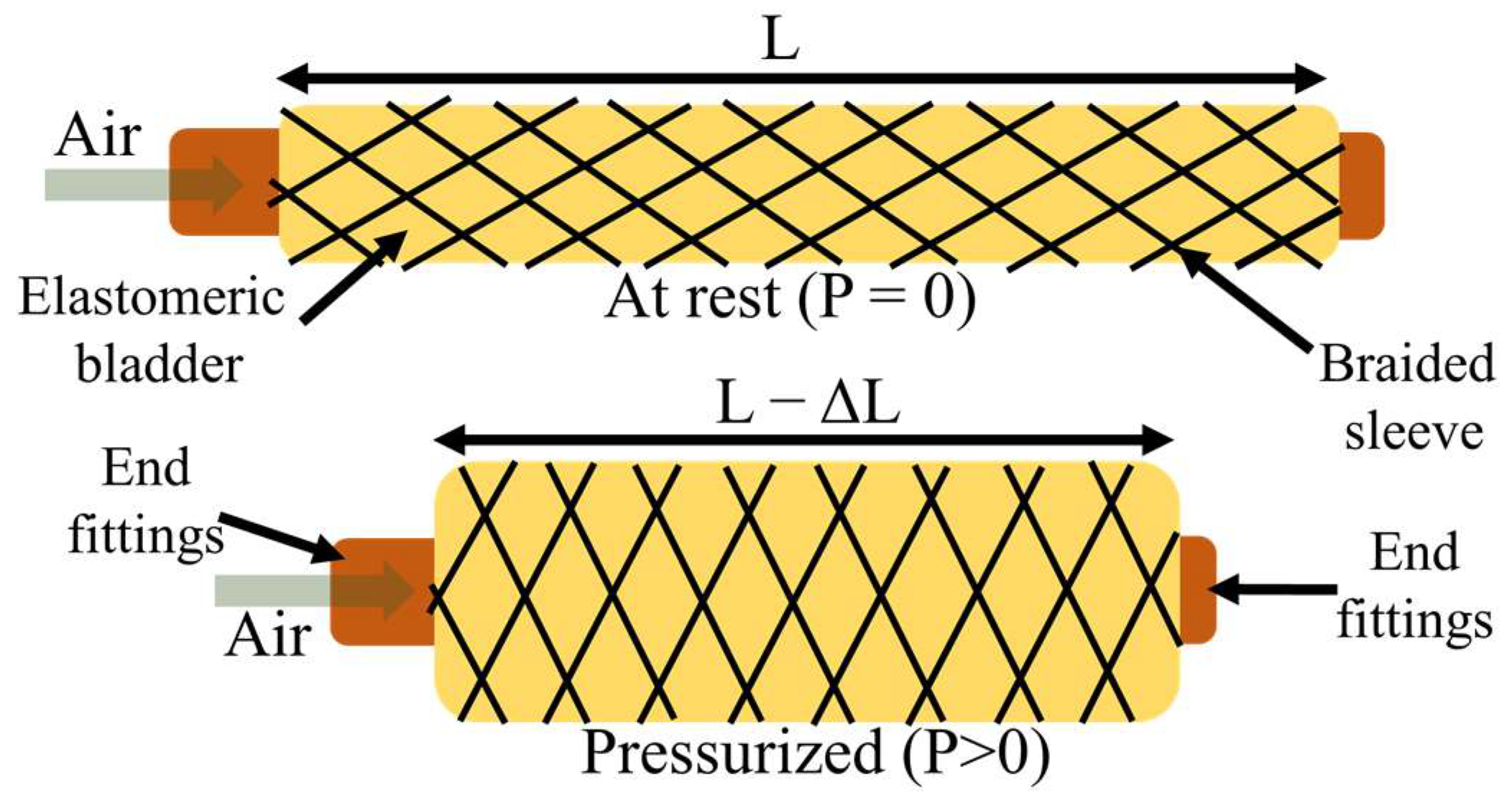
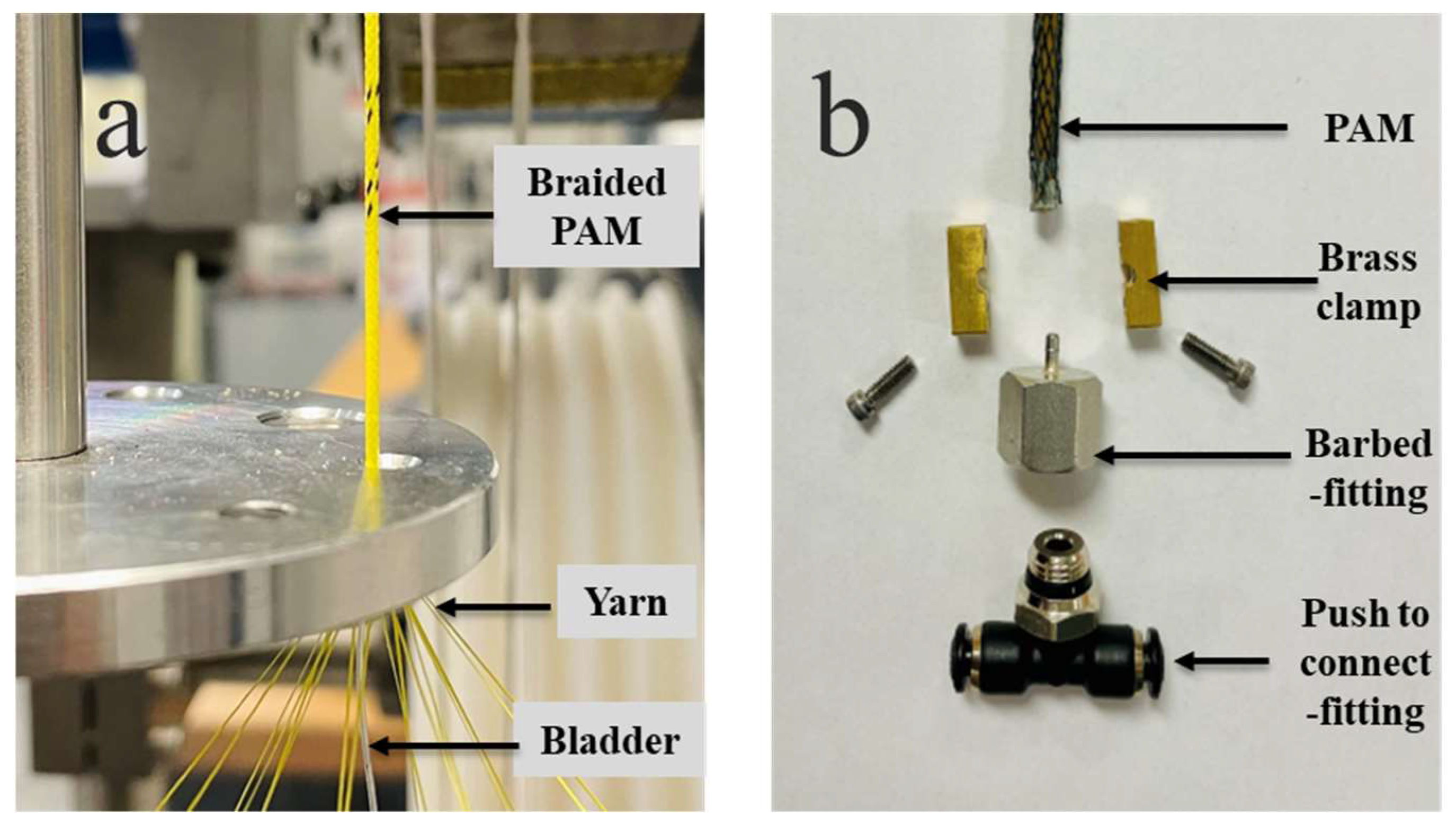
2.2. Fabrication of PAM

A K80-16 vertical braiding machine (Steeger, Inman, SC, USA) with 16 yarn carriers was used for the braiding process (Figure 3a). Two parameters, including picks per inch (PPI) and braiding speed (rev/min), can be controlled from a digital control panel. The PPI value was adjusted by altering the take-up speed while maintaining the yarn carrier moving speed. The braiding speed refers to the productivity here which has no influence on the braiding angle. To change the braiding angle, we can adjust the PPI—the higher the PPI value the larger the braiding angle. In this study, a braiding angle of ~20° was maintained for all types of PAMs because braiding angles between 18° and 30° contribute to the maximum actuation performance [9]. The internal bladders with different dimensions required different PPI values to maintain the ~20° braiding angles of the outer sleeve. The braided actuators were taken up automatically and wound on a bobbin.
The PAM’s specifications are listed in Table 3. The way to label the PAM is to use the bladder tubing sample number followed by that of the yarn used in the braiding sleeve. For instance, “PAM 1-2” refers to the actuator consisting of the #1 tubing bladder listed in Table 2 and the braided sleeve made of #2 yarn listed in Table 1. Figure 4 shows the optical microscope images of all PAM samples.
After braiding, to fabricate the actuators, samples were cut into 20 cm-long pieces with a 3 cm allowance for end-fittings connection. High-pressure barbed fitting in combination with push-to-connect fittings was used as the end fittings, see Figure 3b. Adhesive and mechanical clamps were used to fix the end fittings. For a better seal at the air inlet end, a pair of brass clamps were custom-made. Aluminum tubes and adhesive were used at the blocked end.

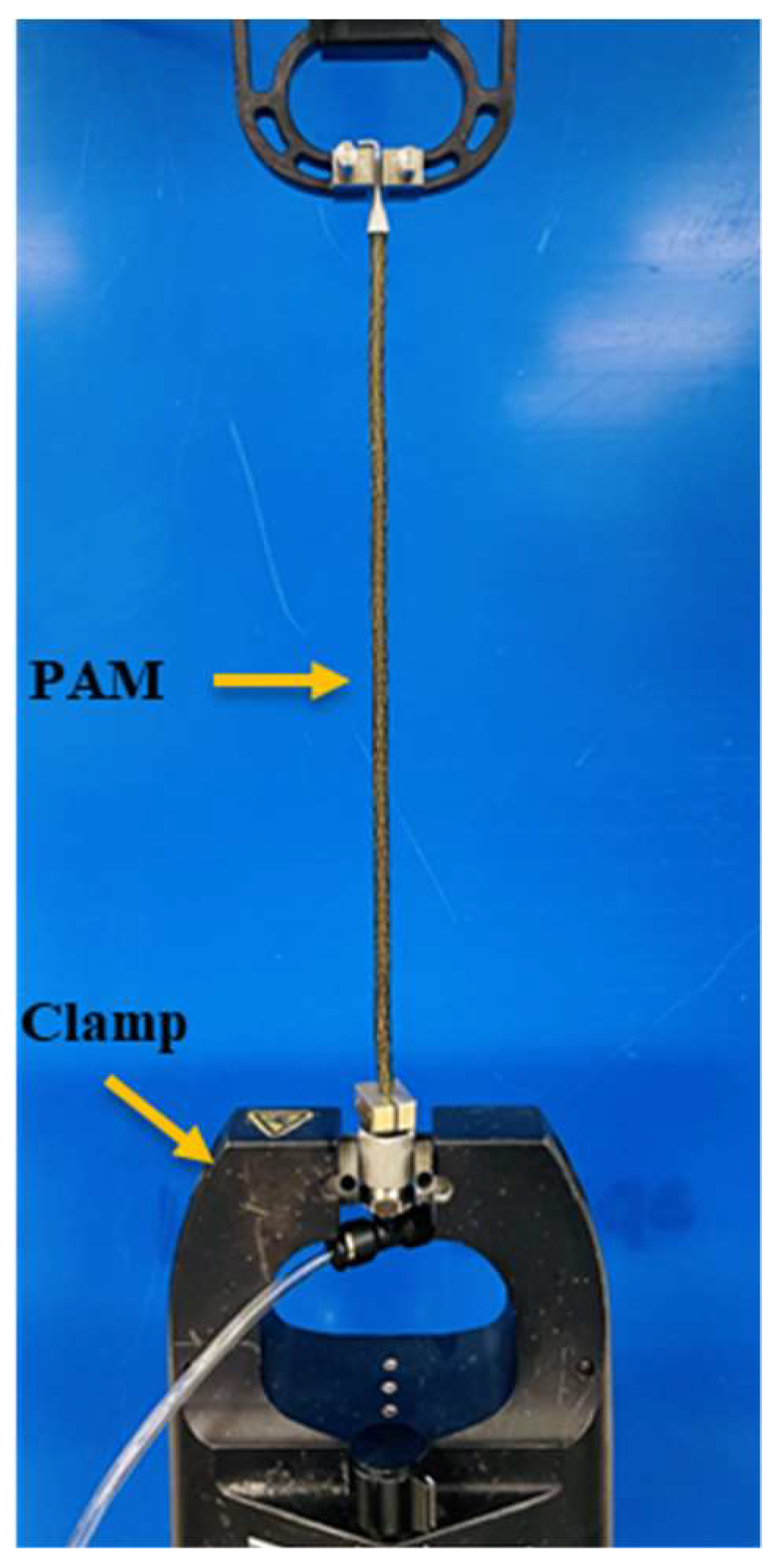
2.3. Characterization of the PAMs

Blocking force and free contraction are two of the most critical properties of PAMs. Blocking force is the contractile force exerted by a PAM under a given pressure while remaining at the initial length. To measure it, as Figure 5 shows, MTS clamps secured the PAM sample’s two ends while it was inflated. The real-time force was recorded by the load cell attached to the top clamp. The air pressure applied was from 100 kPa to 450 kPa for samples made of thick bladders (bladder #1 and bladder #2, since they can only survive up to 450 kPa) and from 250 kPa to 700 kPa for samples using a thin bladder (bladder #3), with an interval of 50 kPa and 100 kPa, respectively. Free contraction is the displacement of a PAM under a specific pressure at “zero load” constraint. The blocking-force test and free-contraction test were conducted in sequence using the same sample without taking it off. After reading the blocking force while the sample was still inflated at a certain pressure, the MTS top clamp moved down at 20 mm/min until the detected load reached zero, where the clamp traveling distance was recorded as the free contraction. The air pressure was controlled by an electro-pneumatic regulator (ITV 3050-21N2BS5, SMC, USA) that also indicates the actual pressure applied to the actuator. This regulator was calibrated using a separate pressure sensor (Amphenol SSI Technologies). For each sample, three specimens were tested.

3. Results and Discussions

The force–contraction results at different pressure levels of all PAM samples are depicted in Figure 6. It shows that the PAM’s blocking force decreases with increasing contraction at a given pressure. From the plots, it is evident that the force–contraction relationship varies while the PAM contracts, which is not a linear correlation. The force drops quickly when the contraction ratio is low (<2%) and follows a nearly linear path in the middle portion of the force–contraction curve and, eventually, a high force drop rate at the maximum contraction ratio, which agrees well with the previously reported works [21,27]. The variation in force drop rates can partly be attributed to the bladder-stiffening effect at higher pressure according to the Mooney–Rivlin model [28,29]. At higher pressure, the silicone bladder is strained beyond its linear stress–strain relationship at a comparatively higher contraction ratio and has entered a stiffening region where stress increases considerably with strain. Another attribute of the miniature silicone bladder is the high bladder volume (Vb) compared to the bladder’s internal hollow space volume (V0). In this study, the average volume ratio (Vb/V0) of the thin PAM was 1.88, which is significantly higher than that of the large-scale McKibben actuator (0.78) [30]. As the silicone bladder comprises a larger portion of the PAM’s cross-sectional area, the bladder’s mechanical properties significantly affect the PAM’s performance. Frictional components such as yarn–yarn friction and yarn–bladder friction during PAM inflation and deflation contribute to the non-linear force–contraction curve [21].
The free contractions and blocking forces results of all PAMs at 450 kPa are summarized in Figure 7. Here, 450 kPa pressure was selected since it is the highest pressure applied to most of the samples (except ones labeled with start marks in this Figure).
In the following sections, we will discuss the influence of yarn stiffness, yarn diameter, bladder size, and bladder hardness on the PAMs’ actuation performance.

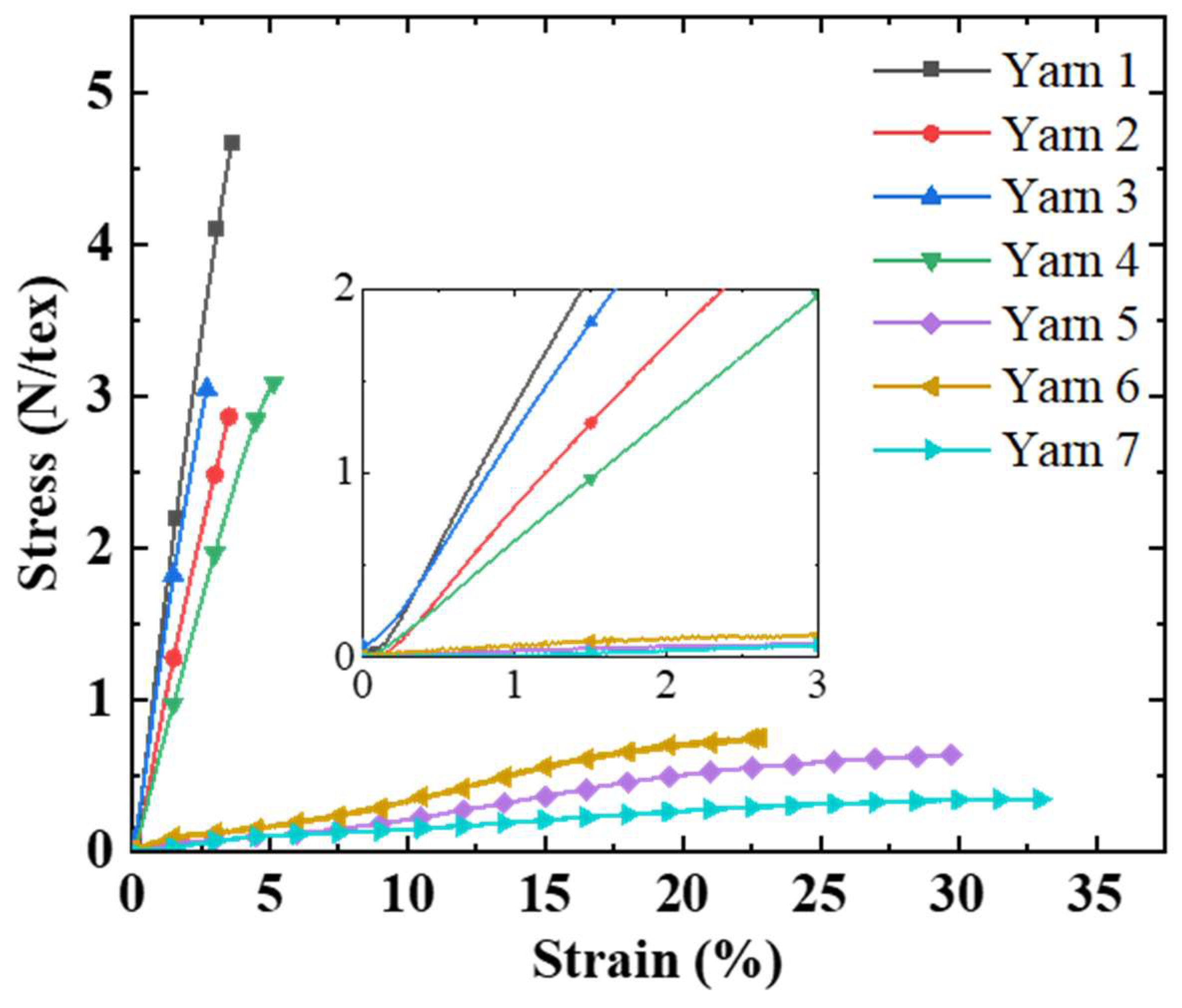
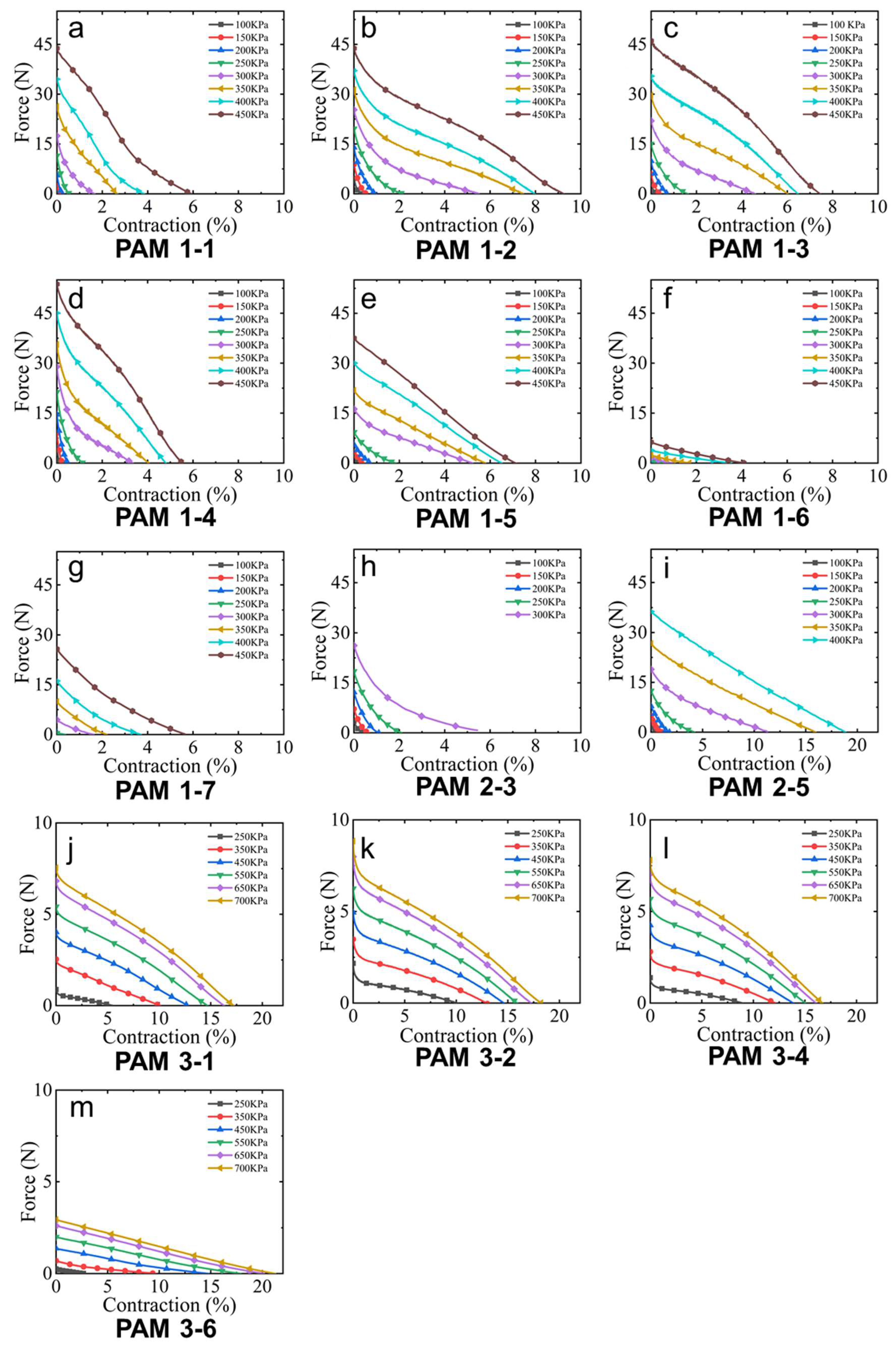
3.1. Effect of Yarn Stiffness

Among PAM 1-1 to 1-7, samples #1-1 and #1-7, #1-2 and #1-6, and #1-3 and #1-5 were three groups using different stiffness yarns while the other parameters were similar. Based on the results shown in Figure 7, samples using yarn #1, #2, and #3 showed a higher blocking force and free contraction in each group. This aligns well with the yarn moduli results. When the blabber is inflated, the expansion force is transferred to the yarns in the sleeve. Yarns with high stiffness can effectively convert this radial expansion into longitudinal contraction by changing the braiding angle without substantial elongations of fibers. Hence, the contraction force and free contraction are higher.
The second set of samples that used yarns with different stiffness, while the other parameters remained similar, was PAM 3-2 and 3-6. These samples used the ultra-thin bladder. It is interesting to notice that the influence of yarn stiffness here was not as significant as that in samples with thick bladders. This was because the force generated by the bladder was smaller than the plastic deformation force of the yarns. In addition, the ultra-thin bladder requires a higher inflating pressure due to Laplace’s law [31].

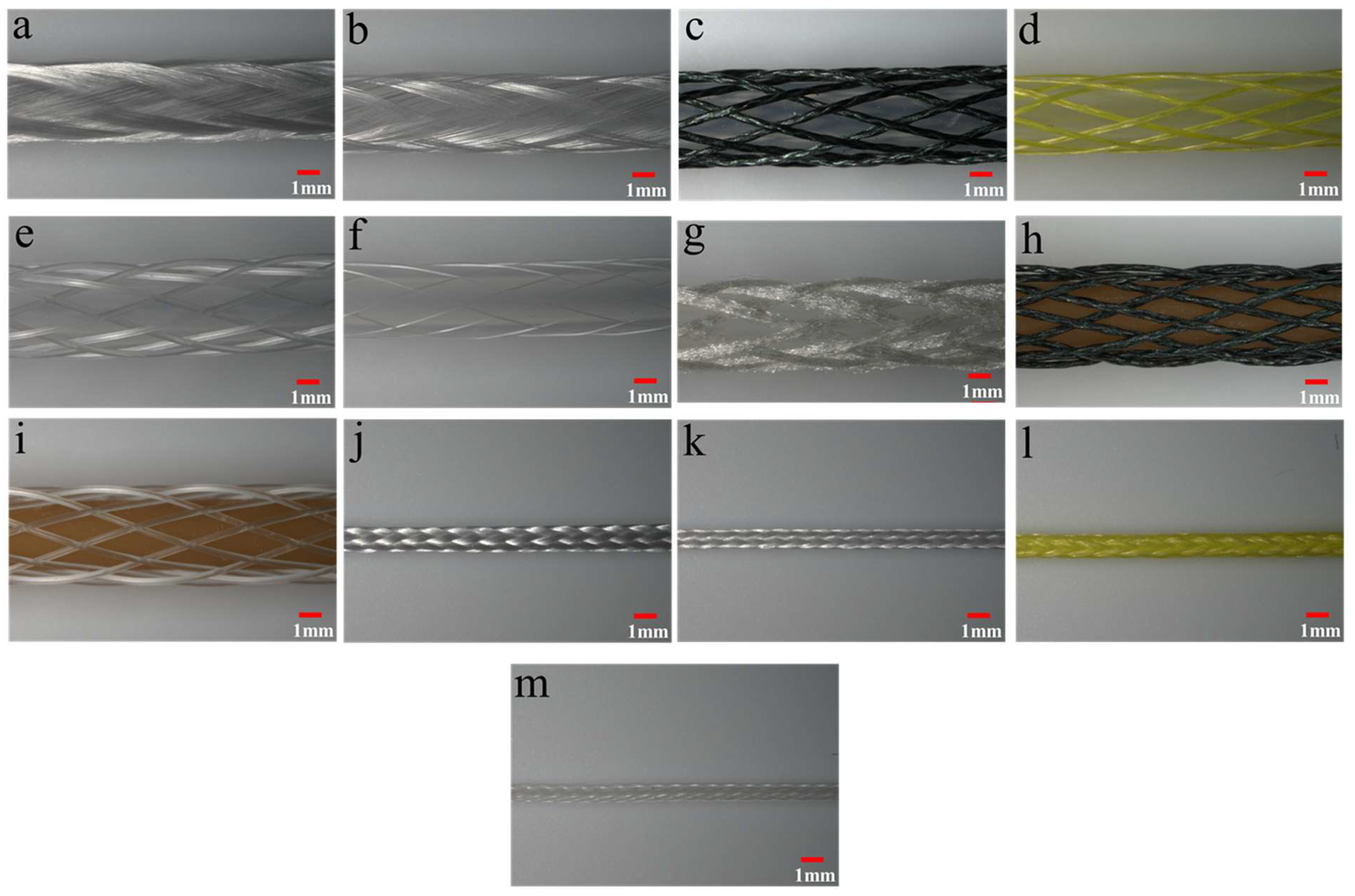
3.2. Effect of Yarn Diameter and Structure

The yarns’ pantograph network in the outer braided sleeve experiences a significant deformation during the PAM actuation process. With the initial braiding angle of ~20°, upon actuation, the pantograph network contracts in a longitudinal direction while the braiding angle increases. Yarn–yarn friction and yarn–bladder friction play very significant roles during this transformation. The friction between the yarns depends on several factors and the two most important factors are the cross-sectional shape and the surface texture of the yarns.
To investigate the yarn size’s effect, comparisons among two sample sets: (1) PAM 1-1 and 1-3 and (2) PAM 1-5, 1-6, and 1-7 were made. It was observed that PAM 1-1 and 1-3 performed similarly since yarn #1 and #3 were exceedingly stiff and they could provide enough force against deformations once their sizes were larger than the threshold value. The actuation properties of PAM 1-5, 1-6, and 1-7 align well with their dimensions, in which PAM 1-5 shows the highest blocking force and free contraction due to its large size, whereas PAM 1-6 performed the least well. This is because, for yarns with similar stiffness, a smaller diameter leads to reduced yarn strength, which, in turn, leads to greater sleeve deformation under the same radial expansion force.
Regarding the yarn structure’s effect, we can compare the performance between PAM 1-2 and 1-4, as well as PAM 3-2 and 3-4. Yarn #4 was a braided yarn that had higher surface friction, and, thus, PAM 1-4 and 3-4 showed slightly lower free contraction in these two groups.

3.3. Effect of Tube Hardness

The PAM’s performance is influenced by the bladder hardness. With increased bladder hardness, PAM’s dead-band pressure will increase. A softer elastomeric bladder ensures lower dead-band pressure and higher deformation of the PAM at the same pressure value. Bladders #1 and #2 have the same dimensions but different shore hardness, in which bladder #2 is softer. As Figure 6 shows, PAM 2-3 and 2-5 expanded more freely and had a larger contraction ratio than #1–3 and #1–5at 300 kPa and 400 kPa, respectively. However, under higher pressure, the soft bladder generally has increased yarn–bladder friction, which interrupts the braid structure from conforming to the optimal configuration under specific pressure. This causes the formation of non-uniform pores in the braid structures. Additionally, the soft bladder can easily bulge out through the larger pores to cause destructive failure, see Figure 8, which was also observed in earlier studies [32,33]. Hence, PAM 2-3 and 2-5 cannot survive at high pressure as other PAMs can. We often observe the bladder bulging through the braiding sleeve and, in turn, breaking down.

3.4. Effect of Bladder Size

The size of the internal elastomeric bladder partially determines the size of the actuator. Some of the earlier research indicates that thin actuators operated by pneumatic pressure led to a reduced contraction ratio [34]. The primary reason is that the ratio of the bladder’s wall thickness to outer diameter was high for the small bladder used in previous work. This hindered the deformation of the bladder under increased pressure [21]. In this study, the bladders’ wall thickness was tailored to maintain a similar ratio of bladder wall thickness to the outer diameter (see Table 2), which helps us to understand the effect of the bladder size exclusively. The thin PAM fabricated with bladder #3 showed a significantly high free contraction as compared to that of the PAM fabricated with bladder #1. The yarn–bladder contact surfaces of PAMs using smaller bladders are exceedingly low relative to that of PAMs using large bladders. As the yarn–bladder friction coefficient is considerably larger, pantograph networks in thin PAMs can transform more freely and achieve a higher contraction ratio. In addition, the braided sleeves are much tighter in the thinner PAMs, which conforms to the bladder wall and thus maximizes the transformation from radial expansion to longitudinal contraction [17].
The PAM’s blocking force is proportional to the square of the bladder’s outer diameter, which indicates that PAM with a larger bladder will generate a substantially large blocking force. The reason is that under a fixed pressure value, a larger surface area will generate a larger force. Hence, the experimental results showed that the PAMs using bladder #1 generated a higher blocking force than that of the PAMs with bladder #3.
In the end, it is worth mentioning that we have observed significant deviations in blocking forces and free contractions in some PAM samples. They can be attributed to the structure nonuniformity that was formed during the braiding processes and handling during the characterization process. This can be improved by using braiders with an advanced yarn tension control system and by selecting optimized braiding angles for specific yarns and bladders.

4. Conclusions

In order to optimize thin McKibben actuators’ design for various robotic applications, in this study, we investigated the influence of the four most critical material properties on thin McKibben actuators’ performance. PAMs with different braided sheath and bladder materials were constructed and experimentally characterized. The key material properties studied here include yarn stiffness, yarn size, bladder size, and bladder durometer hardness. From the experimental analysis, we observed the following relationships between material properties and PAM’s performance.
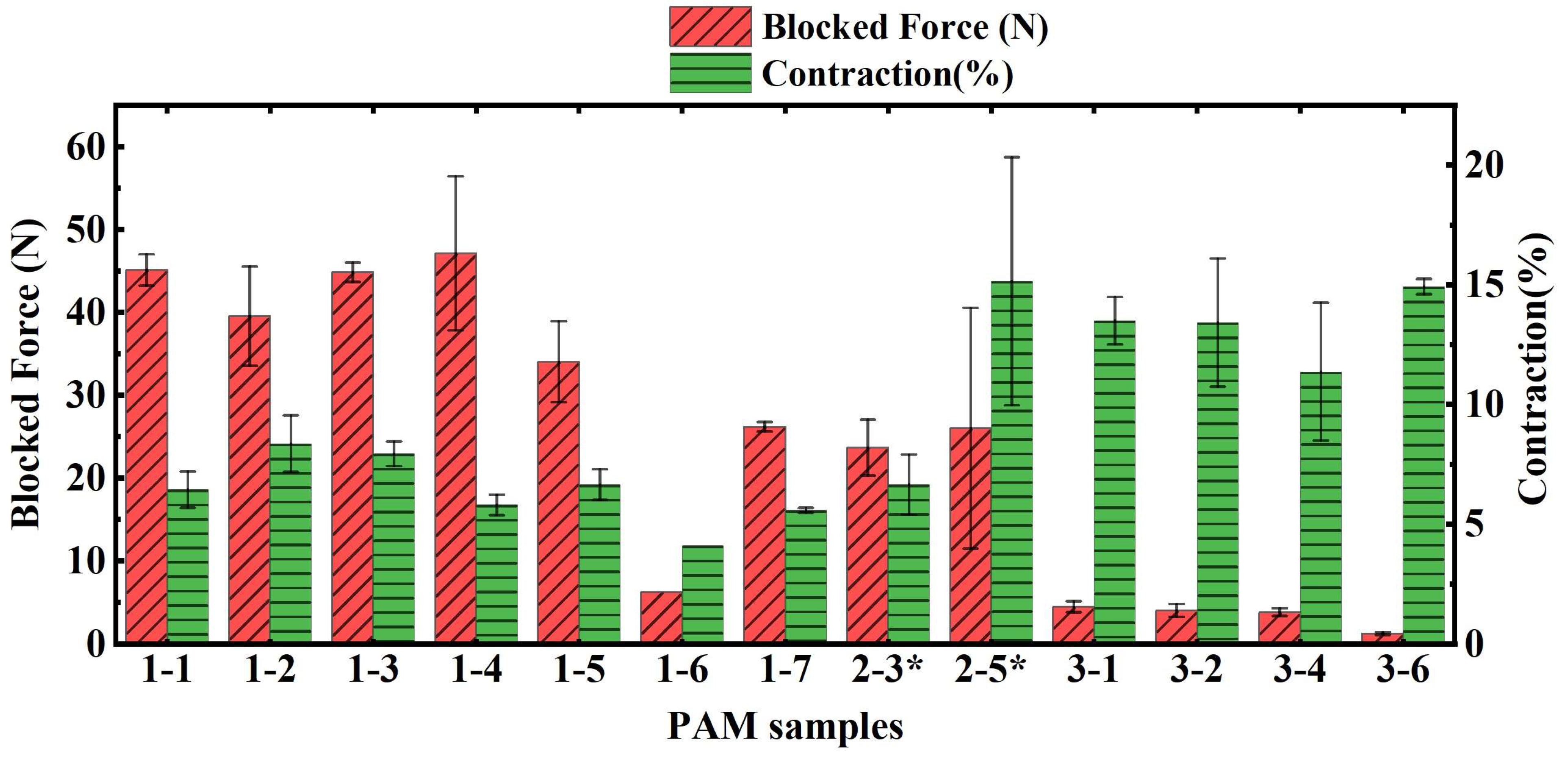
  • The stiffness of the yarn is in direct proportion to PAM’s blocking force. However, it does not have a significant effect on the free contraction of the actuator. Once the yarn stiffness is beyond a certain amplitude, its influence becomes non-significant.
  • Yarn diameter decides its affordable force. Small yarn dimension tends to result in a reduced PAM blocking force. Again, when the yarn’s diameter is large enough and its stiffness is very high, the influence of yarn size is negligible.
  • The yarn structure slightly affects the free contraction ratio of the actuator.
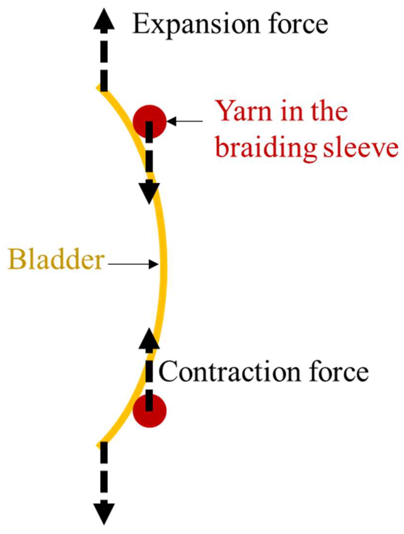
  • Regarding the bladder’s properties, its hardness has an exceeding influence on PAM’s performance. Although the softer bladder is able to generate a higher free contraction of PAM, it can easily bulge out through the braiding sleeve and cause destructive failure. In addition, it is evident that a larger bladder generates significantly higher blocking force but a low free-contraction ratio.
In summary, this paper comprehensively investigated the relationships between materials properties and thin McKibben actuators’ performance. The findings can serve as fundamental guidelines for future design and applications in advanced soft robotics-based thin McKibben actuators. We view the need for future studies to quantitatively understand the contributions of yarn–yarn and yarn–bladder frictions on PAM’s behavior and properties to be important.

Author Contributions

Conceptualization, X.F. and M.A.H.; methodology, X.F. and M.A.H.; formal analysis, M.A.H.; investigation, M.A.H. and E.P.; resources, X.F. and M.A.H.; writing—original draft preparation, M.A.H.; writing—review and editing, M.A.H., E.P. and X.F.; visualization, M.A.H.; supervision, X.F.; project administration, X.F.; funding acquisition, X.F. All authors have read and agreed to the published version of the manuscript.

Funding

This work was funded by the Department of Textile Engineering, Chemistry and Science at NCSU (Startup funding to Xiaomeng Fang).

Data Availability Statement

Not applicable.

Acknowledgments

The authors Xiaomeng Fang, Muh Amdadul Hoque, and Emily Petersen would like to express their gratitude for financial support from the Department of Textile Engineering, Chemistry and Science at North Carolina State University. We thank Eric Lawrence who works at the Nonwovens Institute at North Carolina State University for his technical support in the braider operation; Judy Elson, the departmental chemistry and microscopy lab manager, for her support in the optical microscope operation; and Sen Zhang, a Ph.D. student working in Fang’s lab, for his help in the MTS operation.

Conflicts of Interest

The authors declare no conflict of interest.

References

  1. Klute, G.K.; Czerniecki, J.M.; Hannaford, B. McKibben Artificial Muscles: Pneumatic Actuators with Biomechanical Intelligence. In Proceedings of the 1999 IEEE/ASME International Conference on Advanced Intelligent Mechatronics (Cat. No.99TH8399), Atlanta, GA, USA, 19–23 September 1999; pp. 221–226. [Google Scholar]
  2. Chou, C.-P.; Hannaford, B. Static and Dynamic Characteristics of McKibben Pneumatic Artificial Muscles. In Proceedings of the 1994 IEEE International Conference on Robotics and Automation, San Diego, CA, USA, 8–13 May 1994; Volume 1, pp. 281–286. [Google Scholar]
  3. Liu, C.; Wang, Y.; Qian, Z.; Wang, K.; Zhao, F.; Ding, P.; Xu, D.; Wei, G.; Ren, L.; Ren, L. Bioinspired Actuators with Intrinsic Muscle-like Mechanical Properties. iScience 2021, 24, 103023. [Google Scholar] [CrossRef]
  4. Kurumaya, S.; Suzumori, K.; Nabae, H.; Wakimoto, S. Musculoskeletal Lower-Limb Robot Driven by Multifilament Muscles. Robomech J. 2016, 3, 18. [Google Scholar] [CrossRef] [Green Version]
  5. Wang, X.; Zhang, Y.; Fu, X.; Xiang, G. Design and Kinematic Analysis of a Novel Humanoid Robot Eye Using Pneumatic Artificial Muscles. J. Bionic Eng. 2008, 5, 264–270. [Google Scholar] [CrossRef]
  6. Daerden, F.; Lefeber, D.; Verrelst, B.; Van Ham, R. Pleated Pneumatic Artificial Muscles: Actuators for Automation and Robotics. In Proceedings of the 2001 IEEE/ASME International Conference on Advanced Intelligent Mechatronics, Proceedings (Cat. No.01TH8556), Como, Italy, 8–12 July 2001; Volume 2, pp. 738–743. [Google Scholar]
  7. Zaghloul, A.; Bone, G.M. Origami-Inspired Soft Pneumatic Actuators: Generalization and Design Optimization. Actuators 2023, 12, 72. [Google Scholar] [CrossRef]
  8. Gregov, G.; Ploh, T.; Kamenar, E. Design, Development and Experimental Assessment of a Cost-Effective Bellow Pneumatic Actuator. Actuators 2022, 11, 170. [Google Scholar] [CrossRef]
  9. Ricotti, L.; Trimmer, B.; Feinberg, A.W.; Raman, R.; Parker, K.K.; Bashir, R.; Sitti, M.; Martel, S.; Dario, P.; Menciassi, A. Biohybrid Actuators for Robotics: A Review of Devices Actuated by Living Cells. Sci. Robot. 2017, 2, eaaq0495. [Google Scholar] [CrossRef] [Green Version]
  10. Ashwin, K.P.; Ghosal, A. A Survey on Static Modeling of Miniaturized Pneumatic Artificial Muscles With New Model and Experimental Results. Appl. Mech. Rev. 2018, 70, 040802. [Google Scholar] [CrossRef]
  11. Chen, B.; Zi, B.; Wang, Z.; Qin, L.; Liao, W.-H. Knee Exoskeletons for Gait Rehabilitation and Human Performance Augmentation: A State-of-the-Art. Mech. Mach. Theory 2019, 134, 499–511. [Google Scholar] [CrossRef]
  12. Abe, T.; Koizumi, S.; Nabae, H.; Endo, G.; Suzumori, K.; Sato, N.; Adachi, M.; Takamizawa, F. Fabrication of “18 Weave” Muscles and Their Application to Soft Power Support Suit for Upper Limbs Using Thin McKibben Muscle. IEEE Robot. Autom. Lett. 2019, 4, 2532–2538. [Google Scholar] [CrossRef]
  13. Hiramitsu, T.; Suzumori, K.; Nabae, H.; Endo, G. Experimental Evaluation of Textile Mechanisms Made of Artificial Muscles. In Proceedings of the 2019 2nd IEEE International Conference on Soft Robotics (RoboSoft), Seoul, Republic of Korea, 14–18 April 2019; pp. 1–6. [Google Scholar]
  14. Gorissen, B.; Reynaerts, D.; Konishi, S.; Yoshida, K.; Kim, J.-W.; De Volder, M. Elastic Inflatable Actuators for Soft Robotic Applications. Adv. Mater. 2017, 29, 1604977. [Google Scholar] [CrossRef] [PubMed]
  15. Kilic Afsar, O.; Shtarbanov, A.; Mor, H.; Nakagaki, K.; Forman, J.; Modrei, K.; Jeong, S.H.; Hjort, K.; Höök, K.; Ishii, H. OmniFiber: Integrated Fluidic Fiber Actuators for Weaving Movement Based Interactions into the ‘Fabric of Everyday Life. In Proceedings of the 34th Annual ACM Symposium on User Interface Software and Technology, Virtual, 10–14 October 2021; Association for Computing Machinery: New York, NY, USA, 2021; pp. 1010–1026. [Google Scholar]
  16. Vocke, R.D.; Kothera, C.S.; Chaudhuri, A.; Woods, B.K.S.; Wereley, N.M. Design and Testing of a High-Specific Work Actuator Using Miniature Pneumatic Artificial Muscles. J. Intell. Mater. Syst. Struct. 2012, 23, 365–378. [Google Scholar] [CrossRef]
  17. Tondu, B. Modelling of the McKibben Artificial Muscle: A Review. J. Intell. Mater. Syst. Struct. 2012, 23, 225–253. [Google Scholar] [CrossRef]
  18. Nguyen, P.H.; Zhang, W. Design and Computational Modeling of Fabric Soft Pneumatic Actuators for Wearable Assistive Devices. Sci. Rep. 2020, 10, 9638. [Google Scholar] [CrossRef]
  19. Kurumaya, S.; Nabae, H.; Endo, G.; Suzumori, K. Active Textile Braided in Three Strands with Thin McKibben Muscle. Soft Robot. 2019, 6, 250–262. [Google Scholar] [CrossRef]
  20. Connolly, F.; Walsh, C.J.; Bertoldi, K. Automatic Design of Fiber-Reinforced Soft Actuators for Trajectory Matching. Proc. Natl. Acad. Sci. USA 2017, 114, 51–56. [Google Scholar] [CrossRef] [PubMed] [Green Version]
  21. Hocking, E.G.; Wereley, N.M. Analysis of Nonlinear Elastic Behavior in Miniature Pneumatic Artificial Muscles. Smart Mater. Struct. 2013, 22, 014016. [Google Scholar] [CrossRef]
  22. Gaylord, R.H. Fluid Actuated Motor System and Stroking Device. U.S. Patent No. 2,844,126, 22 July 1958. [Google Scholar]
  23. Schulte, H.F. The Characteristics of the McKibben Artificial Muscle. In The Application of External Power in Prosthetics and Orthotics; National Academy of Sciences-National Research Council: Washington, DC, USA, 1961; Volume Appendix H, pp. 94–115. [Google Scholar]
  24. Andrikopoulos, G.; Nikolakopoulos, G.; Manesis, S. Novel Considerations on Static Force Modeling of Pneumatic Muscle Actuators. IEEE/ASME Trans. Mechatron. 2016, 21, 2647–2659. [Google Scholar] [CrossRef]
  25. Chen, D.H.; Ushijima, K. Prediction of the Mechanical Performance of McKibben Artificial Muscle Actuator. Int. J. Mech. Sci. 2014, 78, 183–192. [Google Scholar] [CrossRef]
  26. Wang, G.; Wereley, N.M.; Pillsbury, T. Non-Linear Quasi-Static Model of Pneumatic Artificial Muscle Actuators. J. Intell. Mater. Syst. Struct. 2015, 26, 541–553. [Google Scholar] [CrossRef]
  27. Kurumaya, S.; Nabae, H.; Endo, G.; Suzumori, K. Design of Thin McKibben Muscle and Multifilament Structure. Sens. Actuators A Phys. 2017, 261, 66–74. [Google Scholar] [CrossRef]
  28. Pillsbury, T.E.; Kothera, C.S.; Wereley, N.M. Effect of Bladder Wall Thickness on Miniature Pneumatic Artificial Muscle Performance. Bioinspiration Biomim. 2015, 10, 055006. [Google Scholar] [CrossRef] [PubMed]
  29. Ball, E.; Lin, Y.; Garcia, E. Characterization and Modeling of Geometric Variations in McKibben Pneumatic Artificial Muscles. In Bioinspiration, Biomimetics, and Bioreplication; SPIE: Bellingham, WA, USA, 2013; Volume 8686, p. 868605. [Google Scholar]
  30. Kothera, C.S.; Jangid, M.; Sirohi, J.; Wereley, N.M. Experimental Characterization and Static Modeling of McKibben Actuators. J. Mech. Des. 2009, 131, 091010. [Google Scholar] [CrossRef]
  31. Plagge, J.; Klüppel, M. Mullins Effect Revisited: Relaxation, Recovery and High-Strain Damage. Mater. Today Commun. 2019, 20, 100588. [Google Scholar] [CrossRef]
  32. Meller, M.A.; Bryant, M.; Garcia, E. Reconsidering the McKibben Muscle: Energetics, Operating Fluid, and Bladder Material. J. Intell. Mater. Syst. Struct. 2014, 25, 2276–2293. [Google Scholar] [CrossRef]
  33. Hawkes, E.W.; Christensen, D.L.; Okamura, A.M. Design and Implementation of a 300% Strain Soft Artificial Muscle. In Proceedings of the 2016 IEEE International Conference on Robotics and Automation (ICRA), Stockholm, Sweden, 16–21 May 2016; pp. 4022–4029. [Google Scholar]
  34. Solano, B.; Rotinat-Libersa, C. Compact and Lightweight Hydraulic Actuation System for High Performance Millimeter Scale Robotic Applications: Modeling and Experiments. J. Intell. Mater. Syst. Struct. 2011, 22, 1479–1487. [Google Scholar] [CrossRef]
Figure 1. The working mechanism of thin McKibben pneumatic artificial muscles.
Actuators 12 00129 g001
Figure 2. Classic stress–strain curves of used yarns. The inset figure shows the results below 3% strain.
Actuators 12 00129 g002
Figure 3. Fabrication of PAM. (a) Braiding PAM using a vertical braiding machine and (b) end fittings assembly for PAM.
Actuators 12 00129 g003
Figure 4. Optical microscopic images of PAM samples. (a) PAM 1-1; (b) PAM 1-2; (c) PAM 1-3; (d) PAM 1-4; (e) PAM 1-5; (f) PAM 1-6; (g) PAM 1-7; (h) PAM 2-3; (i) PAM 2-5; (j) PAM 3-1; (k) PAM 3-2; (l) PAM 3-4; (m) PAM 3-6.
Actuators 12 00129 g004
Figure 5. A PAM sample is mounted on an MTS machine with two clamps fixing the two ends.
Actuators 12 00129 g005
Figure 6. Force–contraction curves of different PAM samples at distinct pressure ranges: (a) PAM 1-1; (b) PAM 1-2; (c) PAM 1-3; (d) PAM 1-4; (e) PAM 1-5; (f) PAM 1-6; (g) PAM 1-7; (h) PAM 2-3; (i) PAM 2-5; (j) PAM 3-1; (k) PAM 3-2; (l) PAM 3-4; (m) PAM 3-6.
Actuators 12 00129 g006
Figure 7. Blocking force and free contraction of different PAM samples at 450 kPa. * PAM 2-3 and 2-5 were actuated at 300 kPa and 400 kPa, respectively, since they did not survive the higher pressure.
Actuators 12 00129 g007
Figure 8. The bulging effect of PAM under high pressure is more prominent for PAMs fabricated with a softer bladder.
Actuators 12 00129 g008
Table 1. Specifications of yarns used in PAM.
Yarn No.MaterialsDiameter
(mm)
Modulus
(N/tex)
Elongation at Break (%)Yarn Type
1Dyneema0.1781.93.6Multifilament
2Dyneema0.08136.42.5Multifilament
3Spectra0.3263.32.7Braided
4Spectra0.10122.05.1Braided
5Nylon0.313.629.7Monofilament
6Nylon0.086.722.8Monofilament
7Polyester0.171.133.0Multifilament
Table 2. Specifications of elastomeric bladders used in PAM.
No.MaterialsOuter Diameter
(mm)
Inner Diameter (mm)Bladder Volume (Vb)/Internal Volume (V0) Ratio between Wall Thickness and ODHardness
(Durometer A)
1Silicone3.171.601.980.2553 A
2Natural Rubber3.171.601.980.2535 A
3Silicone0.500.281.780.2250 A
Table 3. Specifications of PAMs.
Actuator
Samples
Yarn Modulus
(N/tex)
Yarn Diameter (mm)Bladder OD
(mm)
Bladder Hardness
(Durometer A)
Braiding Angle (°)Number of Braiding Yarns in the Sleeve
PAM 1-181.90.173.1753 A2016
PAM 1-2136.40.08
PAM 1-363.30.32
PAM 1-4122.00.10
PAM 1-53.60.31
PAM 1-66.70.08
PAM 1-71.10.17
PAM 2-363.30.3235 A
PAM 2-53.60.31
PAM 3-181.90.170.550 A
PAM 3-2136.40.08
PAM 3-4122.00.10
PAM 3-66.70.08
Disclaimer/Publisher’s Note: The statements, opinions and data contained in all publications are solely those of the individual author(s) and contributor(s) and not of MDPI and/or the editor(s). MDPI and/or the editor(s) disclaim responsibility for any injury to people or property resulting from any ideas, methods, instructions or products referred to in the content.

