
Design, Analysis, and Optimization of a Kinematically Redundant Parallel Robot

Abstract
:1. Introduction
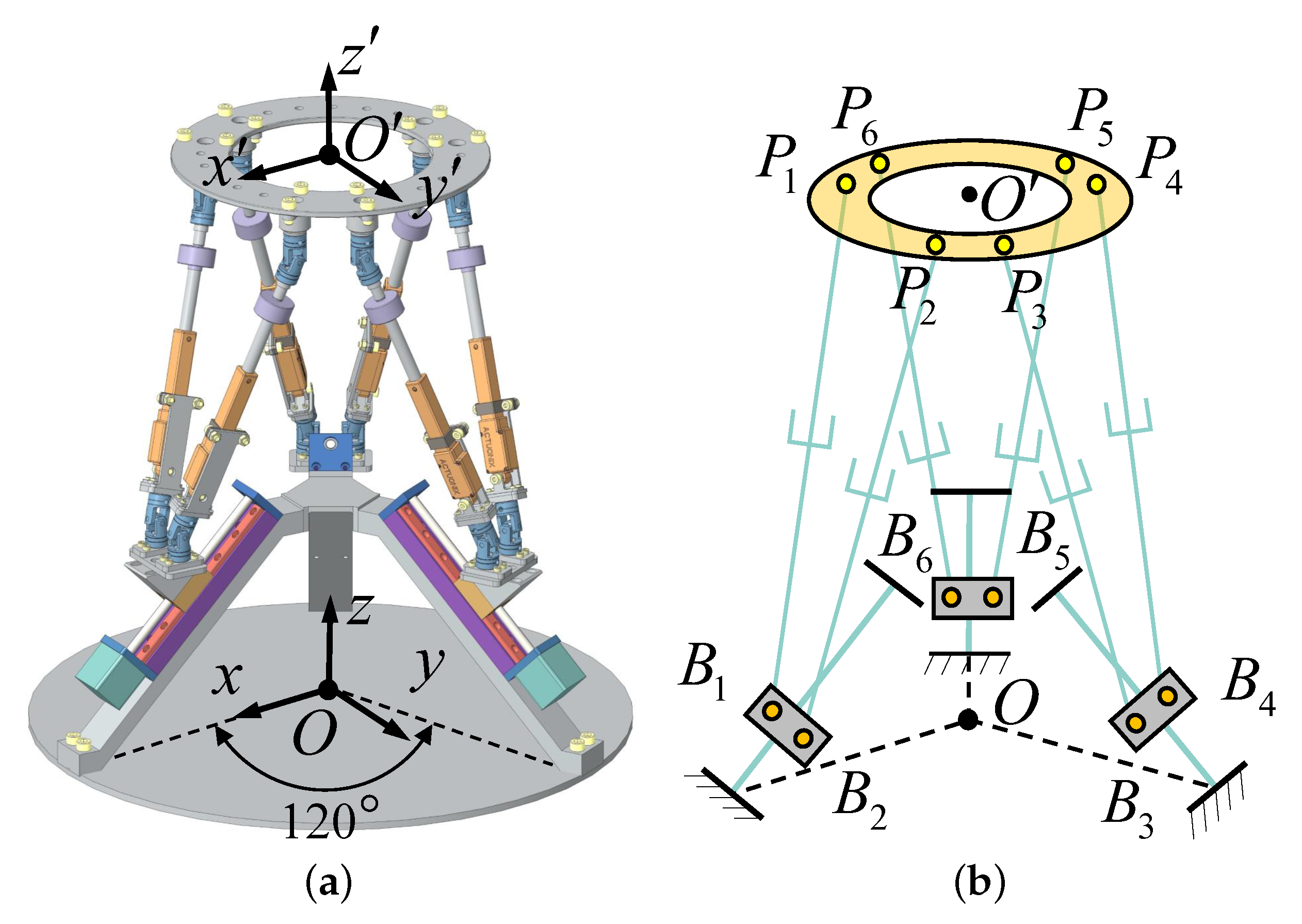
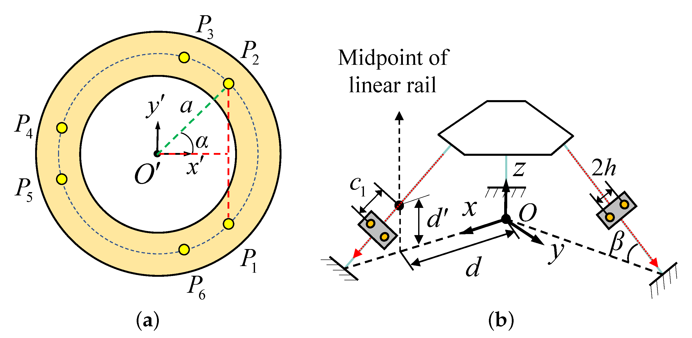
2. Structure and Kinematics
3. Workspace Analysis
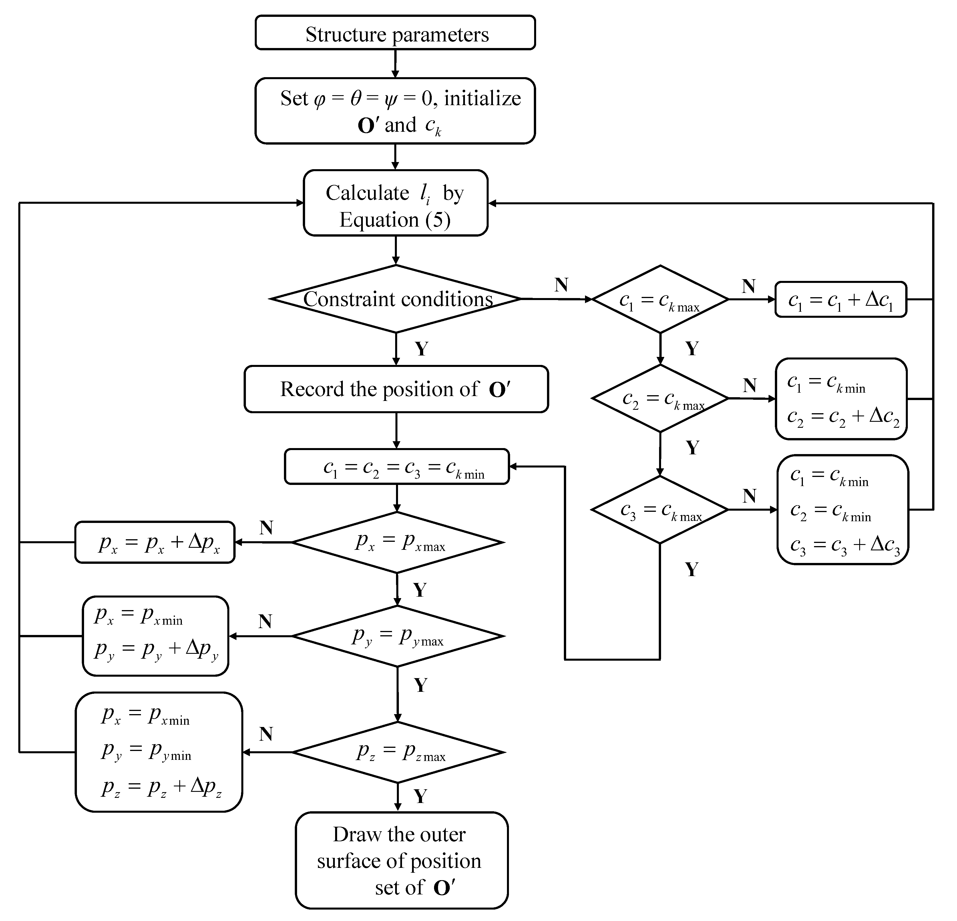
3.1. Position Workspace
- Constraint of leg lengthThe obtained by Equation (5) is required to satisfy the following condition:
- The interference between each legWhen calculating the workspace, legs should avoid interference with each other. According to the literature [28], the constraint condition of interference between legs can be expressed aswhere D is the minimum distance between the central axis of the two arbitrary legs and is the diameter of the legs.
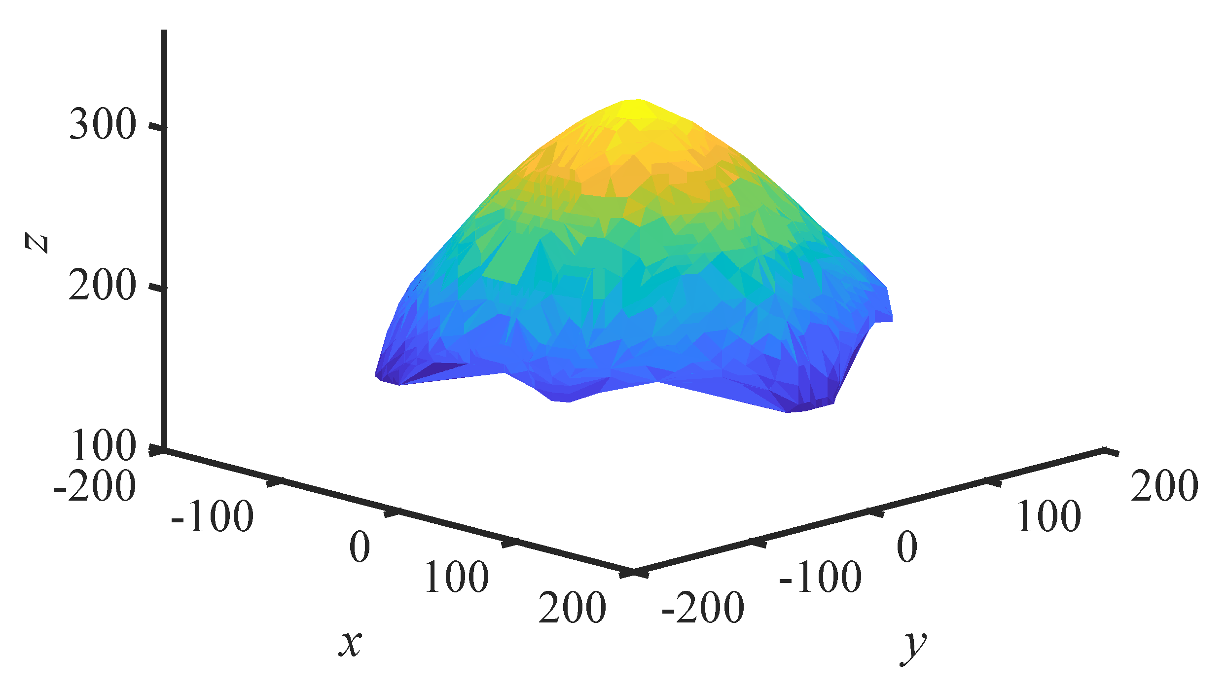
- Singular positionsWhen the robot reaches its singular configuration, the condition number of Jacobian matrix tends to infinity. However, the robot’s motion performance has deteriorated when it is close to the singular configuration. According to the literature [19], the judging condition of a singularity point is selected as for the convenience of calculation when calculating the workspace. The definition of is given in Equation (17). If , in this paper, we deem that the point is a singular position and it will be removed from the position workspace; otherwise, it is not a singular position. The position workspace of the RPRI is shown in Figure 4.


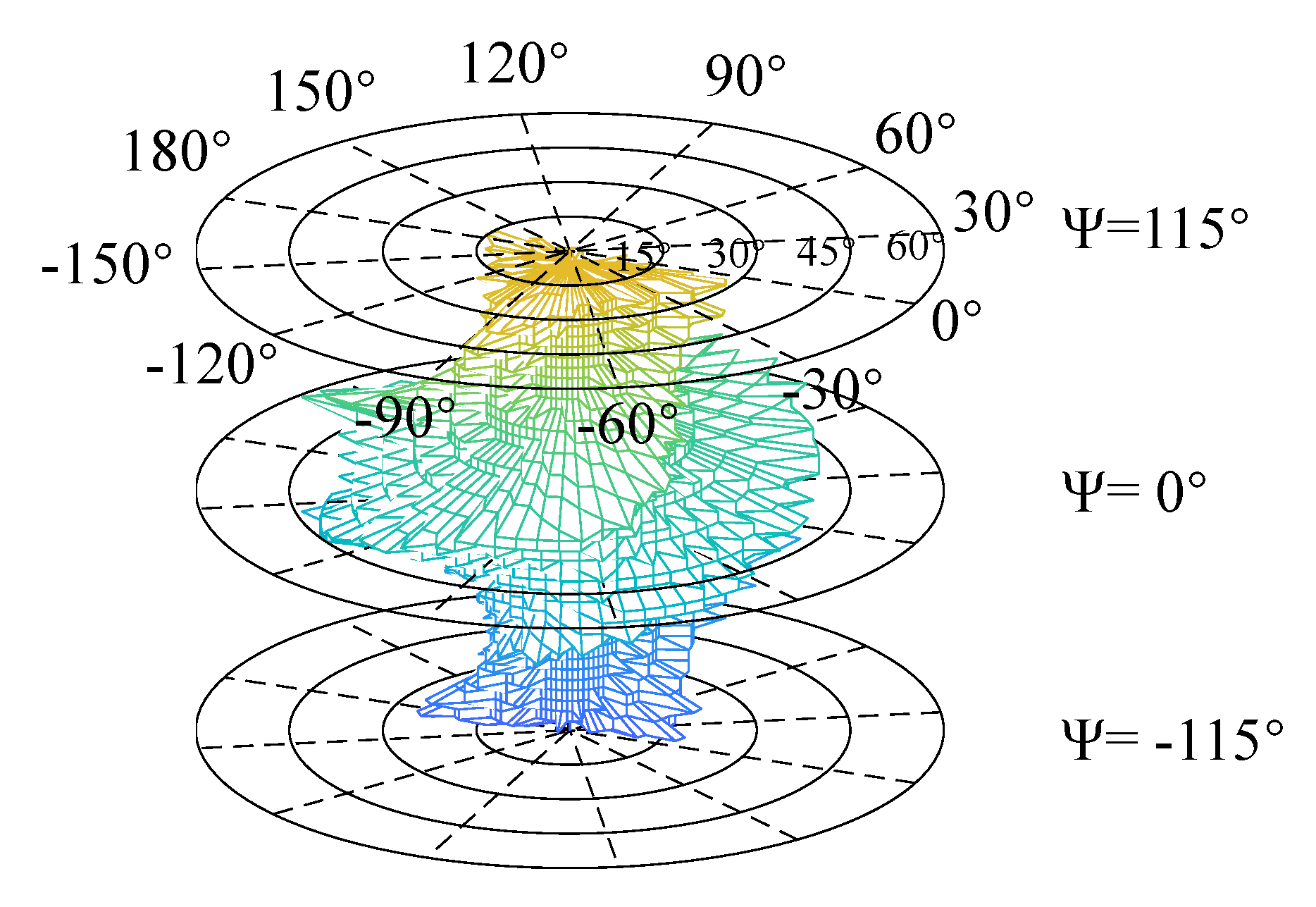
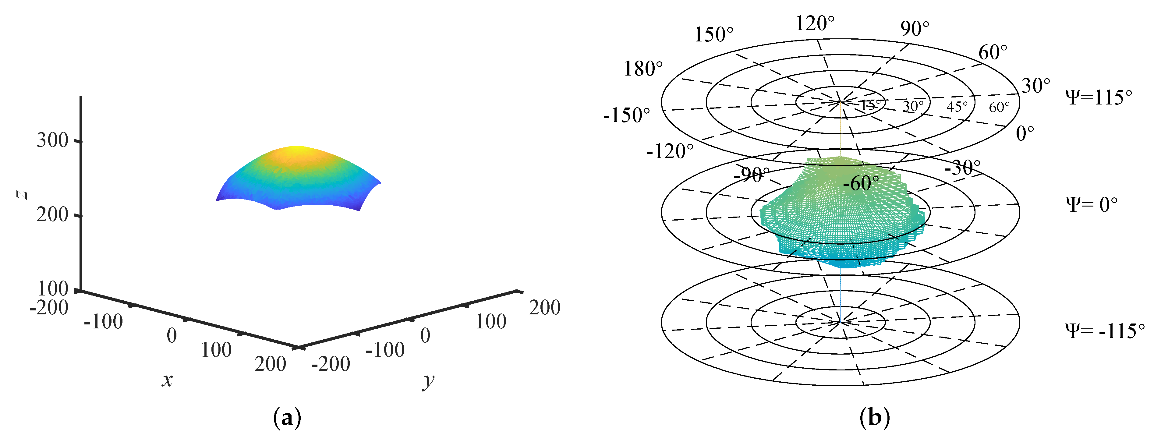
3.2. Orientation Workspace
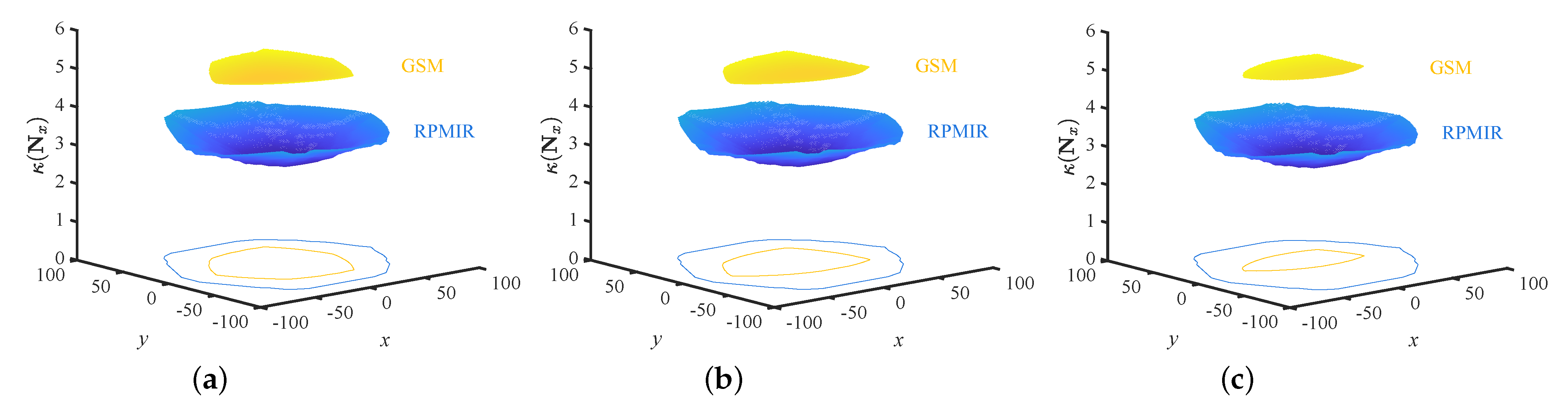
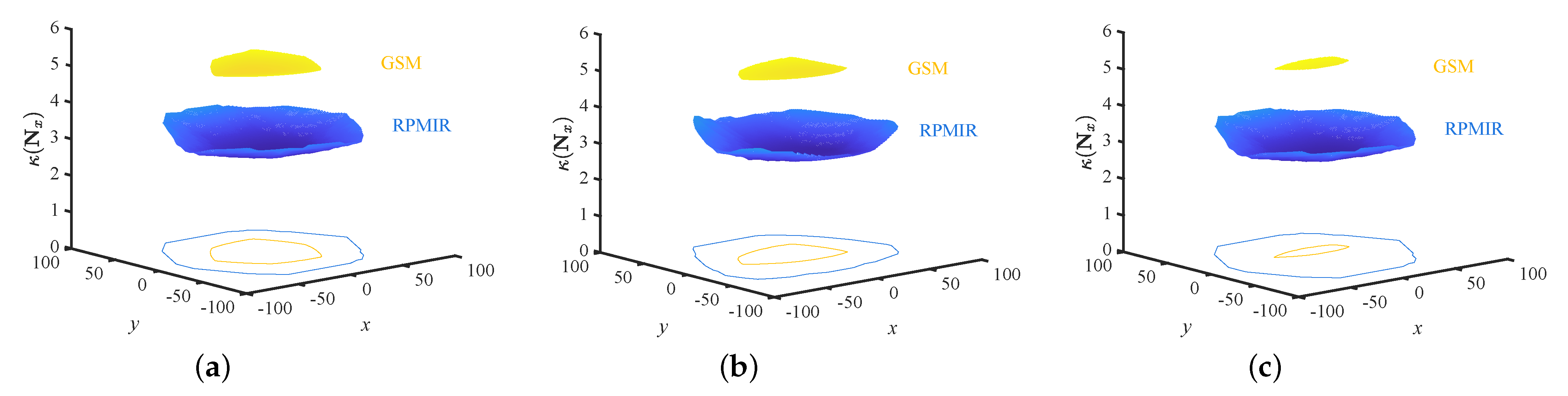
3.3. Comparison with the GSM
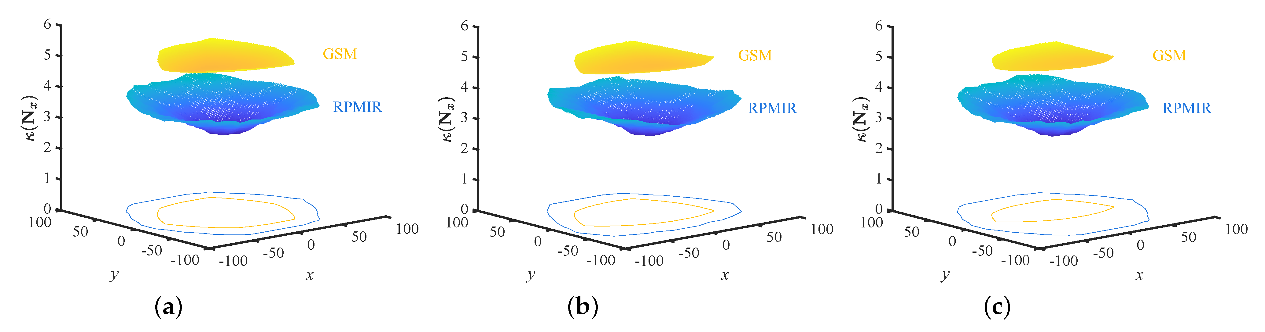
4. Singularity Analysis


5. Optimization and Application
6. Conclusions
- (1)
- The kinematic analysis of the RPRI was presented, and the position and orientation workspaces of the RPRI were calculated. The position and orientation workspaces of the GSM were calculated and compared with the RPRI. The comparison showed that after the introduction of redundancy, the volume of the position workspace increased by 362%, the maximum torsion angle increased by 77%, and the maximum tilt angle increased by 63%.
- (2)
- The dimensionally homogeneous Jacobian matrices were constructed to compare the singularities of the RPRI and the GSM. The condition number distributions of the RPRI and the GSM in different configurations are illustrated to show that RPRI has greater performance in avoiding singularity than the GSM.
- (3)
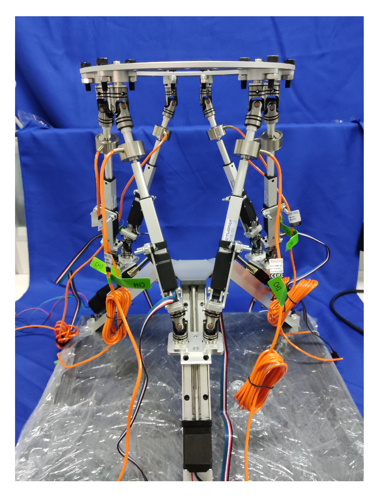
- The multi-parameter, multi-objective genetic algorithm was used to optimize the geometric parameters of the RPRI. On the basis of the optimized results, the experimental prototype of the RPRI was built with the target of fracture reduction surgery.
Author Contributions
Funding
Institutional Review Board Statement
Informed Consent Statement
Data Availability Statement
Conflicts of Interest
References
- Wang, J.; Liu, X.; Wu, C. Optimal design of a new spatial 3-DOF parallel robot with respect to a frame-free index. Sci. China Ser. E-Technol. Sci. 2009, 52, 986–999. [Google Scholar] [CrossRef]
- Furqan, M.; Suhaib, M.; Ahmad, N. Studies on Stewart platform manipulator: A review. J. Mech. Sci. Technol. 2017, 31, 4459–4470. [Google Scholar] [CrossRef]
- Yang, J.; Sun, T.; Cheng, L.; Hou, Z. Spatial repetitive impedance learning control for robot-assisted rehabilitation. IEEE/ASME Trans. Mechatron 2022, 1–11. [Google Scholar] [CrossRef]
- Lu, S.; Ding, B.; Li, Y. Minimum-jerk trajectory planning pertaining to a translational 3-degree-of-freedom parallel manipulator through piecewise quintic polynomials interpolation. Adv. Mech. Eng. 2020, 12, 1–18. [Google Scholar] [CrossRef]
- Gosselin, C. Determination of the workspace of 6-DOF parallel manipulators. J. Mech. Des. 1990, 112, 331–336. [Google Scholar] [CrossRef]
- Kim, D.; Chung, W.; Youm, Y. Geometrical approach for the workspace of 6-DOF parallel manipulators. In Proceedings of the International Conference on Robotics and Automation, Albuquerque, NM, USA, 20–25 April 1997; Volume 4, pp. 2986–2991. [Google Scholar] [CrossRef]
- Merlet, J.P. Determination of 6D workspaces of Gough-Type parallel manipulator and comparison between different geometries. Int. J. Robot. Res. 1999, 18, 902–916. [Google Scholar] [CrossRef]
- Pernkopf, F.; Husty, M.L. Workspace analysis of Stewart-Gough-Type parallel manipulators. Proc. Inst. Mech. Eng. C Mech. Eng. Sci. 2006, 220, 1019–1032. [Google Scholar] [CrossRef]
- Bonev, I.A.; Ryu, J. A new approach to orientation workspace analysis of 6-DOF parallel manipulators. Mech. Mach. Theory 2001, 36, 15–28. [Google Scholar] [CrossRef]
- Jiang, Q.; Gosselin, C.M. Determination of the maximal singularity-free orientation workspace for the Gough–Stewart platform. Mech. Mach. Theory 2009, 44, 1281–1293. [Google Scholar] [CrossRef]
- Yan, Q.; Li, B.; Li, Y.; Zhao, X. Kinematics comparative study of two overconstrained parallel manipulators. Math. Probl. Eng. 2016, 2016, 5091405. [Google Scholar] [CrossRef] [Green Version]
- Li, B.; Li, Y.M.; Zhao, X.H.; Ge, W.M. Kinematic analysis of a novel 3-CRU translational parallel mechanism. Mech. Sci. 2015, 6, 57–64. [Google Scholar] [CrossRef] [Green Version]
- Gosselin, C.; Angeles, J. Singularity analysis of closed-loop kinematic chains. IEEE Trans. Robot. Autom. 1990, 6, 281–290. [Google Scholar] [CrossRef]
- Zlatanov, D.; Bonev, I.; Gosselin, C. Constraint singularities of parallel mechanisms. In Proceedings of the 2002 IEEE International Conference on Robotics and Automation (Cat. No.02CH37292), Washington, DC, USA, 11–15 May 2002; Volume 1, pp. 496–502. [Google Scholar] [CrossRef]
- St-Onge, B.M.; Gosselin, C.M. Singularity analysis and representation of the general Gough-Stewart platform. Int. J. Robot. Res. 2000, 19, 271–288. [Google Scholar] [CrossRef]
- Conconi, M.; Carricato, M. A new assessment of singularities of parallel kinematic chains. IEEE Tran. Robot. 2009, 25, 757–770. [Google Scholar] [CrossRef]
- Sarigul, A.S.; Guneri, B. Some geometric, kinematic, and dynamic considerations on Stewart-Gough platforms with singularity analysis. Robotica 2014, 32, 953–966. [Google Scholar] [CrossRef]
- Saglia, J.A.; Dai, J.S.; Caldwell, D.G. Geometry and kinematic analysis of a redundantly actuated parallel mechanism that eliminates singularities and improves dexterity. J. Mech. Des. 2008, 130. [Google Scholar] [CrossRef]
- Wang, C.; Fang, Y.; Guo, S.; Chen, Y. Design and kinematical performance analysis of a 3-RUS/RRR redundantly actuated parallel mechanism for ankle rehabilitation. J. Mech. Robot. 2013, 5, 041003. [Google Scholar] [CrossRef]
- Gosselin, C.; Schreiber, L.T. Kinematically redundant spatial parallel mechanisms for singularity avoidance and large orientational workspace. IEEE Trans. Robot. 2016, 32, 286–300. [Google Scholar] [CrossRef]
- Wen, K.; Nguyen, T.S.; Harton, D.; Laliberté, T.; Gosselin, C. A backdrivable kinematically redundant (6+3)-degree-of-freedom hybrid parallel robot for intuitive sensorless physical human–robot interaction. IEEE Trans. Robot. 2021, 37, 1222–1238. [Google Scholar] [CrossRef]
- Yan, P.; Huang, H.; Li, B.; Zhou, D. A 5-DOF redundantly actuated parallel mechanism for large tilting five-face machining. Mech. Mach. Theory 2022, 172, 104785. [Google Scholar] [CrossRef]
- Stewart, D. A platform with six degrees of freedom. Proc. Inst. Mech. Eng. 1965, 180, 371–386. [Google Scholar] [CrossRef]
- Raabe, D.; Dogramadzi, S.; Atkins, R. Semi-automatic percutaneous reduction of intra-articular joint fractures - An initial analysis. In Proceedings of the 2012 IEEE International Conference on Robotics and Automation, St Paul, MN, USA, 14–18 May 2012; pp. 2679–2684. [Google Scholar] [CrossRef]
- Li, C.; Wang, T.; Hu, L.; Tang, P.; Wang, L.; Zhang, L.; Guo, N.; Tan, Y. A novel master–slave teleoperation robot system for diaphyseal fracture reduction: A preliminary study. Comput. Assist. Surg. 2016, 21, 162–167. [Google Scholar] [CrossRef] [Green Version]
- Ma, O.; Angeles, J. Optimum architecture design of platform manipulators. In Proceedings of the Fifth International Conference on Advanced Robotics ’Robots in Unstructured Environments, Pisa, Italy, 19–22 June 1991; Volume 2, pp. 1130–1135. [Google Scholar] [CrossRef]
- Bahman, N.; Farid, M.; Mahzoon, M. Redundancy resolution and control of a novel spatial parallel mechanism with kinematic redundancy. Mech. Mach. Theory 2019, 133, 112–126. [Google Scholar] [CrossRef]
- Dong, K.; Li, D.; Xue, X.; Xu, C.; Wang, H.; Gao, X. Workspace and accuracy analysis on a novel 6-UCU bone-attached parallel manipulator. Chin. J. Mech. Eng. 2022, 35, 35. [Google Scholar] [CrossRef]
- Bonev, I.; Zlatanov, D.; Gosselin, C.M. Advantages of the modified Euler angles in the design and control of PKMs. In Proceedings of the 2002 Parallel Kinematic Machines International Conference, Chemnitz, Germany, 23–25 April 2002; pp. 171–188. [Google Scholar]
- Du, J.; Huang, Z.; Yang, R. Optimization of the motion control mechanism of the hatch door of airliner. Struct. Multidiscip. Optim. 2015, 51, 1173–1186. [Google Scholar] [CrossRef]
- Essomba, T.; Nguyen Phu, S. Kinematic analysis and design of a six-degrees of freedom 3-RRPS mechanism for bone reduction surgery. J. Med. Devices 2020, 15, 011101. [Google Scholar] [CrossRef]


| Parameters | Values or Bounds |
|---|---|
| 50 (deg) | |
| a | 70.3 (mm) |
| (180, 240) (mm) | |
| d | 95 (mm) |
| (−50, 50) (mm) | |
| h | 10 (mm) |
| 45 (deg) |
| Volume (mm3) | Torsion Angle (deg) | Tilt Angle (deg) | |
|---|---|---|---|
| GSM | 7.12 | 61 | 27 |
| RPRI | 3.38 | 108 | 44 |
| Parameters | Range |
|---|---|
| (deg) | (0, 60) |
| d (mm) | (70, 235) |
| No. | GCI | V (mm3) |
|---|---|---|
| 1 | 4.70 | 3.82 |
| 2 | 2.15 | 2.99 |
| 3 | 4.99 | 3.87 |
| 4 | 4.17 | 2.81 |
| 5 | 4.38 | 3.41 |
| 6 | 3.39 | 1.99 |
| 7 | 2.71 | 9.93 |
| 8 | 3.91 | 2.77 |
| 9 | 2.34 | 6.17 |
| 10 | 3.00 | 1.49 |
| 11 | 5.31 | 4.30 |
| No. | d (mm) | |
|---|---|---|
| 1 | 55.04 | 99.25 |
| 2 | 54.01 | 192.91 |
| 3 | 52.90 | 95.72 |
| 4 | 51.43 | 107.46 |
| 5 | 54.38 | 103.65 |
| 6 | 53.42 | 120.58 |
| 7 | 50.72 | 142.42 |
| 8 | 54.74 | 110.34 |
| 9 | 53.28 | 162.49 |
| 10 | 53.24 | 131.25 |
| 11 | 55.07 | 90.32 |
Disclaimer/Publisher’s Note: The statements, opinions and data contained in all publications are solely those of the individual author(s) and contributor(s) and not of MDPI and/or the editor(s). MDPI and/or the editor(s) disclaim responsibility for any injury to people or property resulting from any ideas, methods, instructions or products referred to in the content. |
© 2023 by the authors. Licensee MDPI, Basel, Switzerland. This article is an open access article distributed under the terms and conditions of the Creative Commons Attribution (CC BY) license (https://creativecommons.org/licenses/by/4.0/).
Share and Cite
Liang, X.; Zeng, X.; Li, G.; Chen, W.; Su, T.; He, G. Design, Analysis, and Optimization of a Kinematically Redundant Parallel Robot. Actuators 2023, 12, 120. https://doi.org/10.3390/act12030120
Liang X, Zeng X, Li G, Chen W, Su T, He G. Design, Analysis, and Optimization of a Kinematically Redundant Parallel Robot. Actuators. 2023; 12(3):120. https://doi.org/10.3390/act12030120
Chicago/Turabian StyleLiang, Xu, Xiang Zeng, Guotao Li, Wentao Chen, Tingting Su, and Guangping He. 2023. "Design, Analysis, and Optimization of a Kinematically Redundant Parallel Robot" Actuators 12, no. 3: 120. https://doi.org/10.3390/act12030120