Article

An Observer-Driven Distributed Consensus Braking Control Method for Urban Railway Trains with Unknown Disturbances

1
College of Automotive and Mechanical Engineering, Changsha University of Science and Technology, Changsha 410114, China
2
School of Electronic Information and Electrical Engineering, Changsha University, Changsha 410022, China
3
School of Electrical and Information Engineering, Changsha University of Science and Technology, Changsha 410114, China
4
School of Automation, Central South University, Changsha 410083, China
*
Author to whom correspondence should be addressed.
Actuators 2023, 12(3), 111; https://doi.org/10.3390/act12030111
Submission received: 4 February 2023 / Revised: 27 February 2023 / Accepted: 2 March 2023 / Published: 3 March 2023
(This article belongs to the Section Control Systems)

Abstract

:
An urban railway train is a braking power-distributed system consisting of multiple carriages, which is becoming a powerful transportation tool to alleviate traffic congestion within cities as well as across cities. It is critical to control an urban railway train synchronously for improving braking performances, but challenging to be achieved due to strong coupling, unknown dynamics, and disturbances. This paper proposes an observer-driven distributed consensus braking control method for an urban railway train. Specifically, according to the data intersection among carriages, a distributed consensus braking controller is designed to make the velocity of each carriage converge to the desired braking curve. A sliding mode disturbance observer is then developed to estimate the non-linear coupling force and disturbances. The estimation value is utilized to compensate for the distributed consensus braking control law. Moreover, the potential fields are introduced to guarantee that the distances between any two neighbouring carriages are stabilized in a safe range. The effectiveness of the developed control strategy is firstly authenticated via the Lyapunov stability theory and then validated via numerical comparative simulations.

1. Introduction

Urban railway trains have been widely developed in cities all over the world due to their convenience, comfort, rapidity, and environmental friendliness [1]. Due to the dense urban rail lines, a large number of stations, and the short distance between stations, urban rail vehicles need to brake frequently during operation. Therefore, improving the performance of the braking control system is critical to promote the operation efficiency of the urban rail transit system [2].
Guaranteeing the braking safety of urban railway trains is always an important research topic in the field of rail transit systems. For example, an online learning control strategy based on location data of balises was proposed in [3] to improve the braking performance of trains, and a linear uncertain braking model of the train was used to verify the effectiveness of the online learning control scheme. In [4], a precise braking control method was designed for trains by considering modelling errors, unknown perturbations, and occurring failures. In [5], an adaptive non-linear sliding mode control method was developed for the braking control of trains to improve the robustness of the system.
Nevertheless, it should be clarified that the train braking control methods mentioned above mainly pay attention to the improvement of the overall train braking system, and the train dynamics is assumed to be a single mass point model for simplicity [6]. The single mass point model considers the whole train as one single mass point and ignores in-train dynamics [7]. The urban railway train is a braking power-distributed system composed of multiple carriages and hooking devices [8]. The hooking devices are spring-like couplers, which connect the adjacent carriages. For the braking controller design of urban railway trains, the strong coupling characteristics of the inter-connected carriages must be taken into account to ensure braking safety. Otherwise, excessive coupling forces of hooking devices will cause structural damage of carriages and threaten the safety of the train operation. Moreover, the longitudinal impulse of carriages will become significant, affecting the ride comfort of passengers. Hence, it is necessary to put forward an advanced braking control strategy so that the braking velocity of each carriage can be kept consistent and the coupling forces can always be within the safe range.
Cooperative control has been demonstrated as a promising method to address the issues of multi-agent systems, which can make multiple agents synergistically accomplish the desired tasks through the information that agents communicate with each other [9]. Distributed consensus control theory has been applied to the scheduling control and cruise control of multiple trains to ensure the distances between any adjacent trains within the safe range [10]. In [11], a cooperative cruise control strategy was designed for a virtual coupling high-speed train to achieve consistent speed tracking. In [12], a cooperative prescribed performance-tracking control method was proposed for multiple high-speed trains to strictly guarantee the distances between trains in the allowed safe region.
For the cooperative control of multiple trains described in the above literature, only virtual communication connections exist between trains. The adjacent carriages in an urban railway train are connected by hooking devices, where the physical connections are involved in addition to the virtual connections [13]. Higher requirements are put forward to the consensus control of the carriages in an urban railway train. For this purpose, a variety of solutions have been developed to address the cooperative control issues of a single train. For example, a distributed control strategy was designed in [14] to cooperatively track the control of all carriages in a train, where each carriage only uses the measurements of itself and its neighbouring cars. In [15], an undirected graph-based distributed cooperative control law was designed for a high-speed train to achieve displacement and speed consensus among carriages, where the coupler displacements were restricted within a safety constraint. In [16], an event-triggering cooperative control strategy was proposed for a high-speed train to achieve the consensus velocity tracking of carriages, which focused on reducing the communication burden of control systems.
However, to ensure theoretical completeness, the above-mentioned distributed cooperative control strategies have been developed by adopting the linear dynamical models, where the non-linear coupling characteristics and uncertain disturbances are hardly considered. Actually, an urban railway train usually operates in a complex environment. For instance, urban railway trains inevitably operate in the underground, in tunnels, and environments with ramps. Furthermore, the uncertain external disturbance from actual running circumstances and inherent non-linearities of a train may seriously affect the stability of the braking controller. Therefore, both the adjacent coupling non-linear characteristics and unknown external disturbance should be addressed in the design of a safe braking controller. Recently, some decent uncertainty observer methods have been leveraged for the design of various non-linear controllers, such as the high-gain observer [17], inertial-delay observer [18], extended-state observer [19], and sliding-mode observer [20]. The design principle is that the estimated uncertainties are fed back into the system input to achieve active compensation, wherein the designed observers require appreciative estimates of non-linearities and uncertainties [21,22].
On this ground, an observer-driven distributed consensus braking control method is proposed for urban railway trains to achieve velocity consensus among carriages at a desired profile in this work. To counteract the uncertain and non-linear train characteristics, the distributed sliding mode observer is firstly designed to estimate the unknown non-linear dynamics and the uncertain external disturbances, and the estimations are used to compensate the consensus braking controller. Then, the distributed consensus braking controller is developed based on the cooperative control theory, making the velocity of each carriage converge to the desired braking curve in a finite time. Moreover, the potential fields are introduced into the braking controller design to strictly guarantee that the relative displacements between any adjacent carriages are in an expected safe constraint. The stability analysis of the closed-loop control system is proven rigorously. Simulation results verify the feasibility and effectiveness of the proposed method.
The remainder of this paper is organized as follows. In Section 2, system models including the train braking dynamics and communication topology are constructed, and the challenges of braking controller design are analysed. Section 3 elaborates on the proposed observer-driven distributed consensus braking control approach. The simulation results are presented in Section 4. Finally, the paper is concluded in Section 5.

2. System Modelling and Problem Formulation

In this section, a multi-mass braking dynamics model with unknown external resistances is established to characterize the braking motion of a train. In particular, the constructed braking model describes the in-forces caused by the couplers between adjacent carriages. Then, the communication topology among carriages is described by introducing the algebraic graph theory. Finally, a specific consensus braking control issue is presented.

2.1. Train Braking Dynamics

Figure 1 depicts the dynamics of a train during braking. In this figure, x i and v i denote the displacement and velocity of carriage i, respectively; f i denotes the total resistance of carriage i; F a i denotes the actual braking force of carriage i; and Δ l i denotes the deformation length of the coupling spring between carriage i and carriage i + 1 , which can be represented by
Δ l i = x i j 2 d l 0 ,
where x i j = x i x j , d denotes the distance from the mass point to the edge of each carriage, and l 0 is the original length of the coupling spring. Further, using the hardening-spring model, the coupling force between carriage i and carriage i + 1 can be obtained as
Φ i = κ i ( 1 + ϵ i Δ l i 2 ) Δ l i ,
where Φ i denotes the coupling force between carriage i and carriage i + 1 , and κ i and ϵ i are the elastic coefficients of the coupling spring i. Therefore, according to Newton’s second law, the train braking dynamics can be formulated as
x ˙ 1 = v 1 , m 1 v ˙ 1 = F a 1 Φ 1 f 1 , f 1 = f r 1 + f c 1 , F a 1 = K b 1 u 1 , x ˙ i = v i , m i v ˙ i = F a i + Φ i 1 Φ i f i , f i = f r i + f c i , F a i = K b i u i , x ˙ n = v n , m n v ˙ n = F a n + Φ n 1 f n , f n = f r n + f c n , F a n = K b n u n ,
where n is the number of train carriages and i = 1 ; , n , m i is the mass of carriage i; u i is the braking control input of carriage i; and K b i is the braking coefficient of carriage i; The running resistance f r i consists of the rolling mechanical resistance and the aerodynamic resistance. Using the Davis equation, the running resistance f r i can be represented by
f r i = c i 0 + c i 1 v i + c i 2 v i 2 ,
where c i 0 , c i 1 , and c i 3 are the rolling resistance coefficient, drag coefficient, and aerodynamic resistance coefficient, respectively.
The additional resistance f c i is derived from the rail curvatures, slopes, and tunnels. It can be denoted by [23]
f c i = m i g s i n ( θ c i ) + 0.004 m i D c i ,
where the first and second terms represent the influences of the track slope and track curvature, respectively. The parameter θ c i denotes the track slope angle, and the parameter D c i denotes the curvature degree. Nomenclatures are summarized in Table 1.
Notice that the train running conditions are complex and changeable, which leads to difficulties in obtaining external disturbance and resistance. The uncertainties and non-linearities in the train dynamics (3) bring challenges to the design of the train consensus braking controller.

2.2. Communication Topology

The cooperative behaviours among carriages rely on reliable data interaction. A proper train communication topology model is the premise of designing the train consensus braking controller. In this paper, the graph theory is introduced to establish the communication topology model of a train. Defining a graph as G = V , E , wherein V = { 0 , 1 , 2 , , n } represents the set of all nodes, E V × V represents the set of all edges which denote the connectivities among nodes.
From the train model (3), the system states contain the displacement and velocity of carriage i. Thus, the topology models of the velocity and displacement data interaction are investigated. Thus, we define the weighted adjacency matrix about the velocity data interaction as A a = [ a i j ] R n × n , and define the weighted adjacency matrix about the displacement data interaction as A b = [ b i j ] R n × n . If the corresponding velocity or displacement data can be communicated between nodes i and j, the weight a i j = 1 or b i j = 1 ; otherwise, the weight a i j = 0 or b i j = 0 . Further, the degree matrix about the velocity data interaction can be obtained as D a = d i a g d a 1 , d a 2 , , d a n with d a i = a i j . The degree matrix about the displacement data interaction can be represented by D b = d i a g d b 1 , d b 2 , , d b n with d b i = b i j .
For a general urban railway train with six carriages, i.e., n = 6 , the velocity data of each carriage can be exchanged through the CAN bus. Therefore, the Laplacian matrix about the velocity data interaction can be obtained as
L a = D a A a = 5 1 1 1 1 1 1 5 1 1 1 1 1 1 5 1 1 1 1 1 1 5 1 1 1 1 1 1 5 1 1 1 1 1 1 5 .
However, the displacement data interaction of an urban railway train is different from the velocity data interaction mentioned above. The effect of the displacement needs to be transmitted through the couplers between carriages, so only two adjacent carriages can exchange the displacement data with each other. Therefore, the Laplacian matrix about the displacement data interaction can be obtained as
L b = D b A b = 1 1 0 0 0 0 1 2 1 0 0 0 0 1 2 1 0 0 0 0 1 2 1 0 0 0 0 1 2 1 0 0 0 0 1 1 .
The data interaction relationships among carriages are fixed when a train runs on the railway. Therefore, the Laplacian matrices L a and L b remain unchanged.

2.3. Consensus Braking Problem

The connection mode between adjacent carriages can be regarded as an elastic mechanical connection. To ensure the operation safety of a train, the coupling force generated by the relative displacement between adjacent carriages should be strictly restricted within a bounded safety range. The upper and lower bounds of the relative displacement between adjacent carriages are defined as θ 1 and θ 2 , respectively. Then, the consensus braking objective can be designed as follows:
lim t x i x j = θ i j , θ i j [ θ 1 , θ 2 ] , lim t v i v j = 0 .
Furthermore, each carriage of a train must track the desired braking curve synchronously to satisfy the brake requirements. The desired velocity can be designed as follows:
v ( t ) = v ( t 0 ) a r · t ,
where v ( t 0 ) denotes the initial consensus velocity, and a r denotes the desired deceleration under the different braking modes.
It can be concluded that the appreciated consensus braking controller should be developed to achieve the following main tasks:
(i)
The actual velocities of all carriages rapidly converge to the desired braking curve, achieving the velocity consensus finally.
(ii)
In the whole process of converging to the desired braking curve, the relative displacements between any adjacent carriages should always satisfy the safety constraint.

3. Cooperative Braking Controller Design

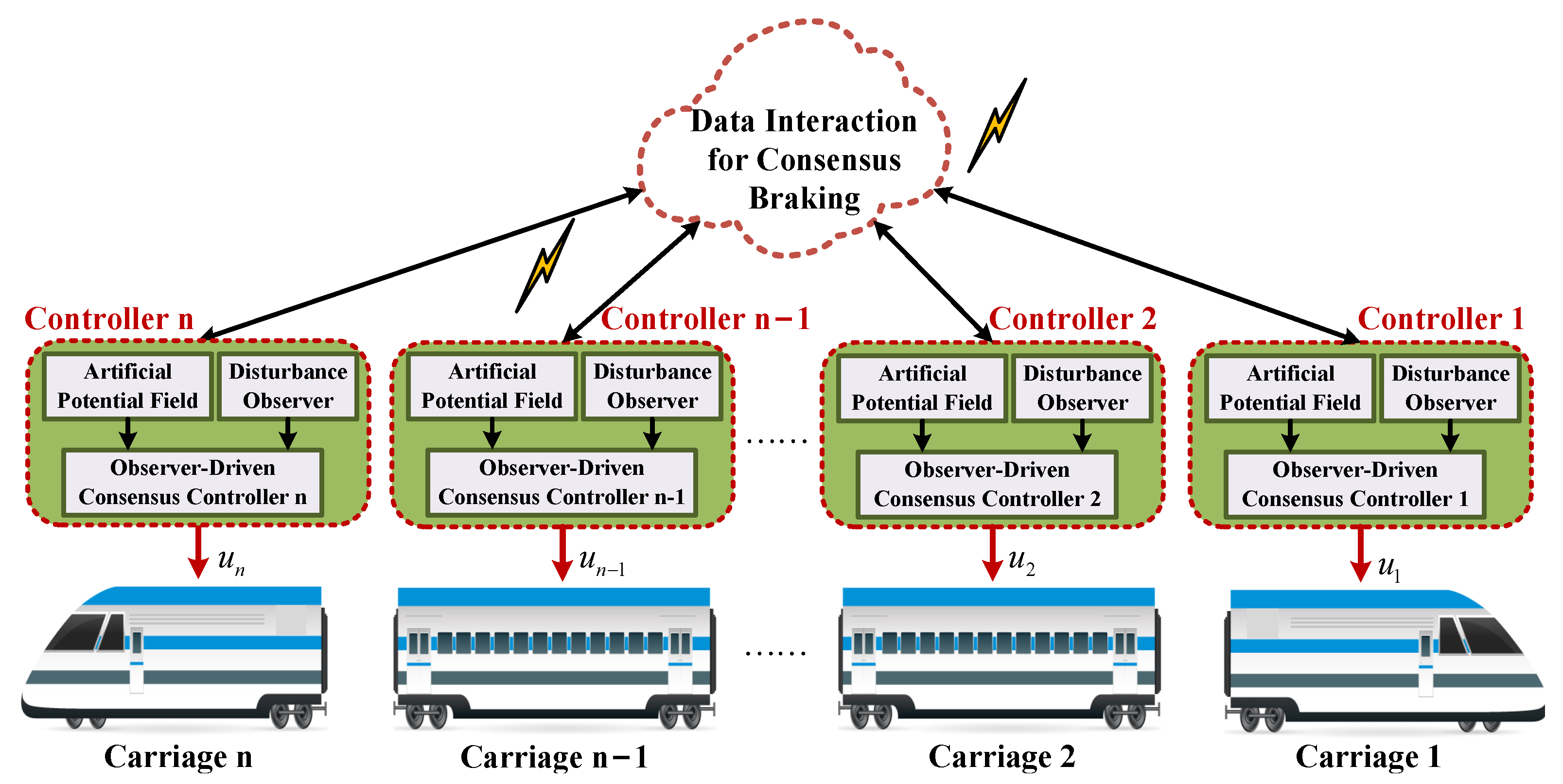
In this section, an observer-driven distributed consensus braking controller is developed. Firstly, a sliding mode disturbance observer is designed to estimate the total uncertainties including the non-linear coupling force and external disturbances. The estimation result is also utilized to compensate for the subsequent consensus control law. Then, a basic consensus braking controller is developed by introducing the cooperative control theory, and the potential field functions are adopted to guarantee the relative displacements between any adjacent carriages stabilizing in a safety range. Finally, the stability analysis of the proposed control approach is presented. Figure 2 depicts the framework diagram of the proposed approach.

3.1. Sliding-Mode Disturbance Observer

In the train braking process, the resistance encountered by the train includes not only air resistance, but also the track slope resistance and track curvature resistance. These resistances cannot be accurately formulated. Moreover, the coupling force between any adjacent carriages possesses a serious non-linear characteristic. Therefore, this paper leverages a sliding-mode disturbance observer to deal with the non-linearities and uncertainties in the system model (3).
In practical application, both the non-linear coupling force Φ i and the uncertain resistance f i of each carriage are bounded. Defined as φ i = Φ i 1 Φ i f i , and the system dynamics model (3) can be rewritten as
x ˙ 1 = v 1 , m 1 v ˙ 1 = K b 1 u 1 + φ 1 , x ˙ i = v i , m i v ˙ i = K b i u i + φ i , x ˙ n = v n , m n v ˙ n = K b n u n + φ n .
Utilizing Equation (10), the sliding mode disturbance observer can be designed as follows:
x ^ ˙ i ( t ) = v ^ i ( t ) + γ i 1 s i g n ( e i 1 ) , v ^ ˙ i ( t ) = K b i u i ( t ) m i + γ i 2 s i g n ( e i 2 ) ,
where x ^ i ( t ) and v ^ i ( t ) represent the estimation values of the displacement and velocity for carriage i, respectively; e i 1 and e i 2 represent the estimation errors of the displacement and velocity, respectively, and γ i 1 and γ i 2 are the observer gains.
Then, the estimation error vector can be defined as
e i = e i 1 e i 2 T = x i x ^ i v i v ^ i T ,
and the estimation error dynamics of the sliding-mode disturbance observer can be obtained as
e ˙ i 1 = e i 2 γ i 1 s i g n ( e i 1 ) , e ˙ i 2 = φ i γ i 2 s i g n ( e i 2 ) .
The following Lyapunov function can be designed
V i = 1 2 e i T e = 1 2 ( e i 1 2 + e i 2 2 ) ,
and the derivative of the Lyapunov function taken:
V ˙ i = e i 1 e i 1 ˙ + e i 2 e i 2 ˙ = e i 1 e i 2 γ i 1 s i g n ( e i 1 ) + e i 2 φ i γ i 2 s i g n ( e i 2 ) = e i 1 e i 2 γ i 1 e i 1 s i g n ( e i 1 ) + e i 2 φ i γ i 2 e i 2 s i g n ( e i 2 ) ,
According to the properties of the sign function, the following formula holds:
| e i 1 | = e i 1 s i g n ( e i 1 ) , | e i 2 | = e i 2 s i g n ( e i 2 ) .
Thus, we can obtain:
V ˙ i = e i 1 e i 2 γ i 1 | e i 1 | + e i 2 φ i γ i 2 | e i 2 | e i 1 ( | e i 2 | γ i 1 ) + e i 2 ( φ i γ i 2 ) min { ( | e i 2 | γ i 1 ) , ( φ i γ i 2 ) } e i 1 .
To make the derivative of the Lyapunov function a negative definite, the designed observer gains should satisfy
γ i 1 | e i 2 | 0 , γ i 2 φ i 0 .
Then, the designed disturbance observer will converge in finite time. Thus, the estimation error satisfies
e i = e i 1 = 0 , e i 2 = 0 ,
and the derivative of the estimation error satisfies
e ˙ i = e ˙ i 1 = 0 , e ˙ i 2 = 0 .
By substituting the error Equation (13), we can obtain:
x i = x ^ i , e i 2 = γ i 1 s i g n ( e i 1 ) , v i = v ^ i , φ i = γ i 2 s i g n ( e i 2 ) .
In finite time, the external disturbance and the non-linear part of the system dynamics can be expressed as
lim t φ ^ i = φ i = γ i 2 s i g n ( γ i 1 s i g n ( x i x ^ i ) ) .
To sum up, if Condition (18) is satisfied, δ ¯ > 0 , t l < T l , ∀ t > t l ,
| φ ^ i φ i | < δ ¯ .

3.2. Observer-Driven Consensus Braking Control

In this subsection, based on the established communication topology models, an observer-driven consensus braking controller is designed to achieve the above-proposed cooperative train brake tasks by utilizing the above-estimated value φ ^ i . The basic form of the developed consensus braking controller for each carriage is represented as follows:
u i = u i 1 + u i 2 + u i 3 ,
where the term u i 1 guarantees all carriages achieve the velocity consensus based on the consensus control algorithm, u i 2 is the artificial potential field function which, in part, ensures the relative displacements between any adjacent carriages are maintained within the safety region, and u i 3 denotes the observer-driven controller part, which is adopted to compensate for the uncertainties and non-linearities in the train braking dynamics.

3.2.1. Design of the Consensus Control Algorithm

The inconsistent rail condition and resistance lead to velocity differences between the carriages, which will cause the coupling between adjacent carriages to squeeze or stretch. Therefore, it is necessary to design a consensus protocol to guarantee the velocity differences between any adjacent carriages rapidly converge to zero and the relative displacement between any adjacent carriages is within a safe range.
For the velocity and displacement consistencies, the consensus control approach is designed based on the established communication topology models as follows:
u i 1 = α 1 j = 1 n a i j ( v i v j ) + α 2 j = 1 n b i j ( x i x j θ i j ) ,
where the α 1 and α 2 are the controller parameters, and α 1 > 0 , α 2 > 0 .

3.2.2. Design of the Artificial Potential Field

This subsection presents an artificial potential field function to strictly guarantee that the displacement differences between any adjacent carriages are maintained within the safety region. The artificial potential field function can be designed as follows:
U i j ( x i j ) = 1 | x i j | 2 θ 1 2 + 1 θ 2 2 | x i j | 2 , θ 1 < x i j < θ 2 .
The controller component based on the artificial potential field function can be denoted as
u i 2 = δ j = 1 n b i j U i j ( x i j ) ,
where δ > 0 is the controller parameter.
For the designed artificial potential field function in Equation (26), if the velocity difference between adjacent carriages is little and the corresponding relative displacement is within the safe deformation range of carriage couplers, i.e., θ 1 < x i j < θ 2 , the artificial potential field function will produce a little and stable control output. However, once the relative displacement between adjacent carriages is close to or reaches the defined safety region. The artificial potential field function will produce a large control effect on the designed controller to avoid damage caused by the excessive deformation of the carriage coupler.

3.2.3. Anti-Disturbance Control Design

The designed sliding disturbance observer can identify the uncertainties and non-linearities in the train braking dynamics. Based on the designed disturbance observer, the anti-disturbance control component is developed to make the velocity of each carriage follow the desired velocity curve under the uncertain disturbances. This control component can ensure that the tracking error v e i ( t ) = v i ( t ) v ( t ) is within a certain stable region under the external disturbance, where the external uncertain disturbance should be bounded.
According to the estimated value φ ^ i and the corresponding estimation error D i , given the desired velocity, the following formula can be obtained:
x ˙ i = v i , m i v ˙ i = K b i u i + ( φ ^ i D i ) .
Based on the above observer convergence analysis, we can calculate whether the estimation error D i is bounded. Furthermore, we can define the upper bound as Ω , i.e., | D i | Ω < . The anti-disturbance control law can be designed as
u i 3 = m i ( k i v e i + v ) + k d i φ ^ i ,
where k i and k d i are the control parameters, and k i > 0 , k d i > 0 .

3.3. Stability Analysis

This subsection investigates the stability of the proposed consensus braking controller. We can define x i x l 0 = x ˜ i , v i v = v ˜ i , and the tracking error dynamics can thus be obtained as:
x ˜ ˙ i = v ˜ i , v ˜ ˙ i = j = 1 n a i j ( v i v j ) j = 1 n b i j ( x i x j ) j = 1 n b i j U i j ( x i j ) K b i k i v e i K b i v D i ,
Defining X ˜ = x ˜ 1 , x ˜ 2 , , x ˜ n T , V ˜ = v ˜ 1 , v ˜ 2 , , v ˜ n T , M = L a + d i a g a 10 , a 20 , , a n 0 , N = L b + d i a g b 10 , b 20 , , b n 0 , R = D 1 K b 1 v , D 2 K b 2 v , , D n K b n v T ,
K = d i a g K b 1 k 1 , K b 2 k 2 , , K b n k n , E = v e 1 , v e 2 , , v e n T ,
U = j = 1 n b 0 j U ˜ 0 j ( x 0 j ) , j = 1 n b 1 j U ˜ 1 j ( x 1 j ) , , j = 1 n b n j U ˜ n j ( x n j ) T , the tracking error dynamics in Equation (30) can be further represented by
X ˜ ˙ = V ˜ , V ˜ ˙ = M V ˜ N X ˜ U K E + R .
According to the developed control input, as shown in Equation (24), and the tracking error dynamics, as shown in Equation (30), the Lyapunov function can be defined as
V = V ˜ T V ˜ + X ˜ N X ˜ + i = 0 n j = 0 n b i j U ˜ i j ( x i j ) ,
which represents the systematic energy for the tracking error dynamics (Equation (30)), satisfying the premised condition V > 0 .
It is worth noting that both Laplacian matrices L a and L b are positive definites, satisfying
L a > 0 and L b > 0 .
Thus, the designed Lyapunov function is a positive definite. The derivative of the Lyapunov function can be denoted as
V ˙ = 2 V ˜ T V ˜ ˙ + 2 V ˜ N X ˜ + i = 0 n j = 0 n b i j U ˜ ˙ i j ( x i j ) = 2 V ˜ T ( M V ˜ N X ˜ U K E + R ) + 2 V ˜ T N X ˜ + i = 0 n j = 0 n b i j U ˜ ˙ i j ( x i j ) = 2 V ˜ T M V ˜ 2 V ˜ T N X ˜ 2 V ˜ T U 2 V ˜ T K E + 2 V ˜ T R + 2 V ˜ T N X ˜ + i = 0 n j = 0 n b i j U ˜ ˙ i j ( x i j ) = 2 V ˜ T M V ˜ 2 V ˜ T U 2 V ˜ T K E + 2 V ˜ T R + i = 0 n j = 0 n b i j U ˜ ˙ i j ( x i j ) = 2 V ˜ T M V ˜ 2 V ˜ T ( K V ˜ R ) 2 V ˜ T U + i = 0 n j = 0 n b i j U ˜ ˙ i j ( x i j )
Further, we can obtain
V ˙ 2 V ˜ T M V ˜ 2 V ˜ 1 K b i k i m i n + 2 V ˜ 1 Ω i m a x 2 V ˜ T U + i = 0 n j = 0 n b i j U ˜ ˙ i j ( x i j ) = 2 V ˜ T M V ˜ 2 V ˜ 1 ( K b i k i m i n Ω i m a x ) 2 V ˜ T U + i = 0 n j = 0 n b i j U ˜ ˙ i j ( x i j ) ,
The derivative of the term U ˜ satisfies
U ˜ ˙ ( X ˜ ) = V ˜ U ˜ ( X ˜ ) .
Then, the derivative of the term i = 0 n j = 0 n b i j U ˜ ˙ i j ( x i j ) in Equation (35) can be obtained as
i = 0 n j = 0 n b i j U ˜ ˙ i j ( x i j ) = i = 0 n j = 0 n b i j ( v i + v j ) U ˜ ˙ i j ( x i j ) = 2 V ˜ T U
Substituting Equation (37) into Equation (35), we can further obtain
V ˙ = 2 V ˜ T M V ˜ 2 V ˜ 1 ( K b i k i m i n Ω i m a x )
When the control parameters K b i k i > Ω i m a x , the stability of designed controller can be achieved. It means that the velocity tracking error of each carriage can converge to zero in a finite time, satisfying
lim t v i v = 0 .
Moreover, the specific characteristics of the introduced artificial potential field function can ensure that the relative displacements between any adjacent carriages do not exceed the prescriptive safety region while the velocities of each carriage converge, i.e., satisfying
lim t x i x j = θ i j , θ i j θ 1 , θ 2
Based on the above stability analysis, the proposed controller can achieve displacement and velocity consistency, while ensuring the relative displacements between any adjacent carriages are within a safety constraint and converge to the nominal value. The proposed controller has no requirement on the number of carriages due to the inherent characteristics of the distributed cooperative control theory. This means that the proposed consensus braking controller can be extended to other formations of urban railway trains; for example, a train with four or eight carriages.

4. Simulation Results

In this section, the simulation tests are conducted to validate the proposed observer-driven distributed consensus braking controller. The effectiveness and superiority of the proposed control method have been verified in various operational scenarios.
Firstly, the desired braking curve of the virtual leader is set, and each carriage of an urban railway train is defined as the follower. The initial velocity of the virtual leader is defined as v ( t 0 ) = 90 km/h, and the corresponding deceleration is defined as a = 3.5 km/(h·s). Then, the desired braking curve of the virtual leader can be calculated by v ( t ) = v ( t 0 ) a · t . The sampling time is set as 1 ms. In practical application, urban railway trains have high requirements for safety and riding comfort. The relative coupler displacements between adjacent carriages represent a critical indicator of safety and riding comfort. Thus, refer to [24], the constraint of the relative displacement between adjacent carriages can be set as [ 1 , 1 ] cm. The main simulation parameters of the proposed controller are presented in Table 2.
Furthermore, to better verify the performance of the proposed control approach, the simulation scenarios were designed by the following cases: (i) Fine railway condition and no external disturbances; (ii) Poor railway condition and no external disturbances; (iii) Poor railway condition and existing external disturbances.
  • Case 1: Fine railway condition and no external disturbances.
In this case, the wheels of an urban railway train do not skid under a fine railway condition, and therefore each carriage’s braking capacity can satisfy the braking requirements of the desired braking curve. 
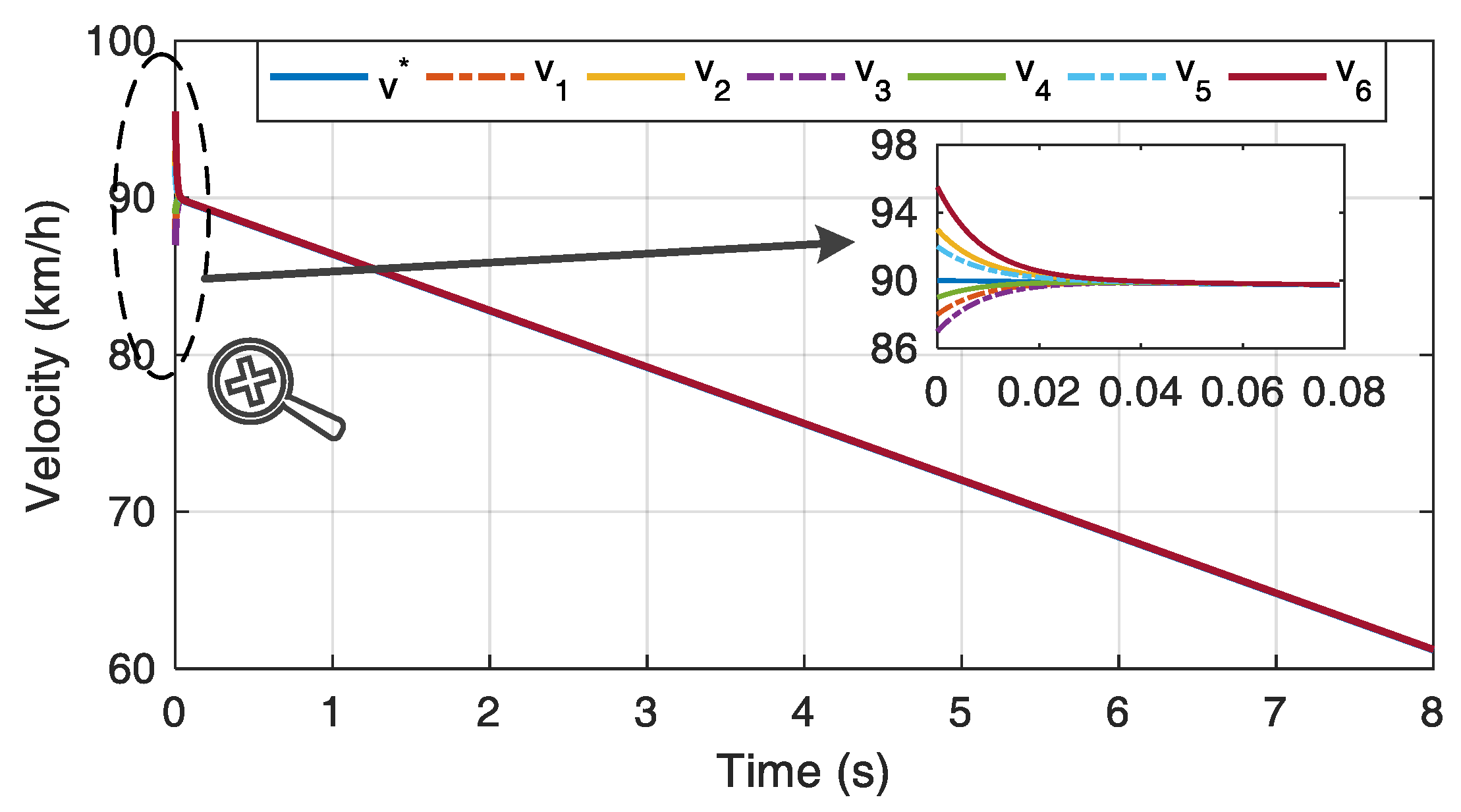
Figure 3 presents the consensus braking curves of each carriage in case 1. As shown in Figure 3, at the different initial values of carriage velocity, the proposed consensus braking controller can make the velocity of each carriage rapidly converge to the desired braking curve and be in consensus with each other. The convergence time is less than 0.04 s.
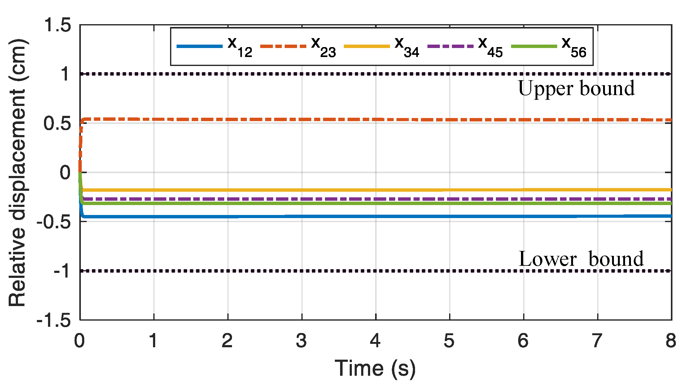
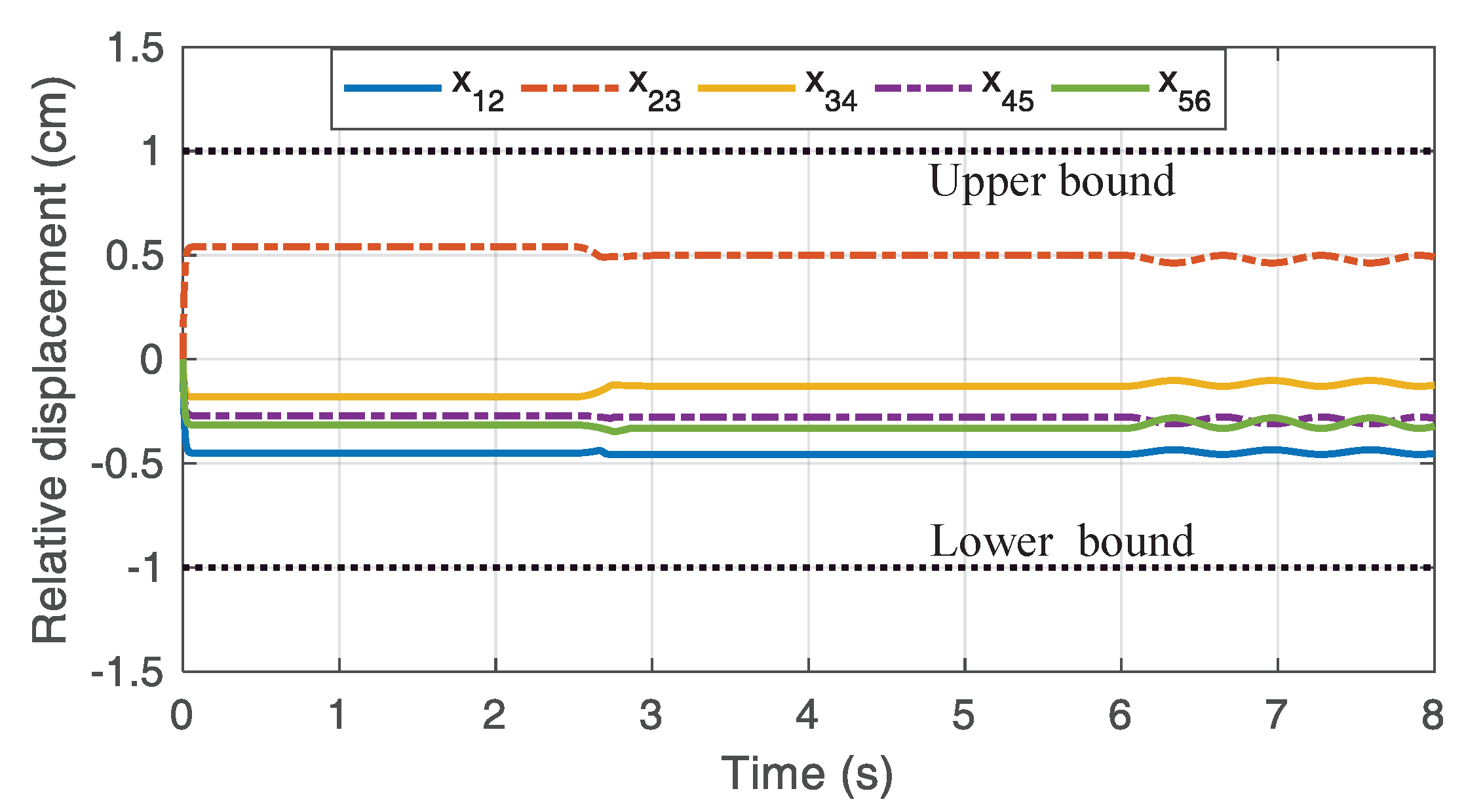
Figure 4 provides the relative displacement variations between any adjacent carriages. Owing to the artificial potential field function, the relative displacements between any adjacent carriages always meet the safety constraint [ 1 , 1 ] 
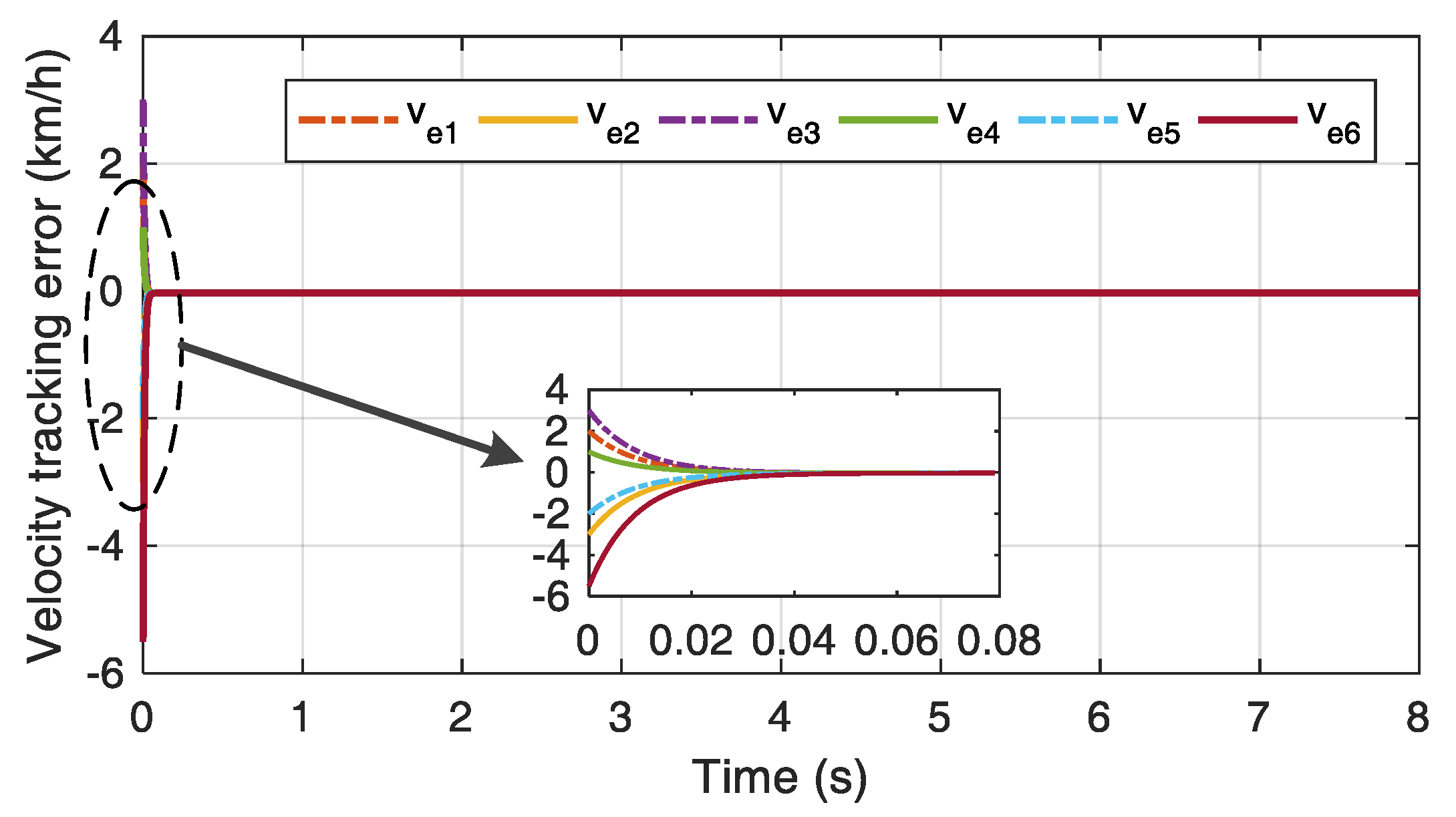
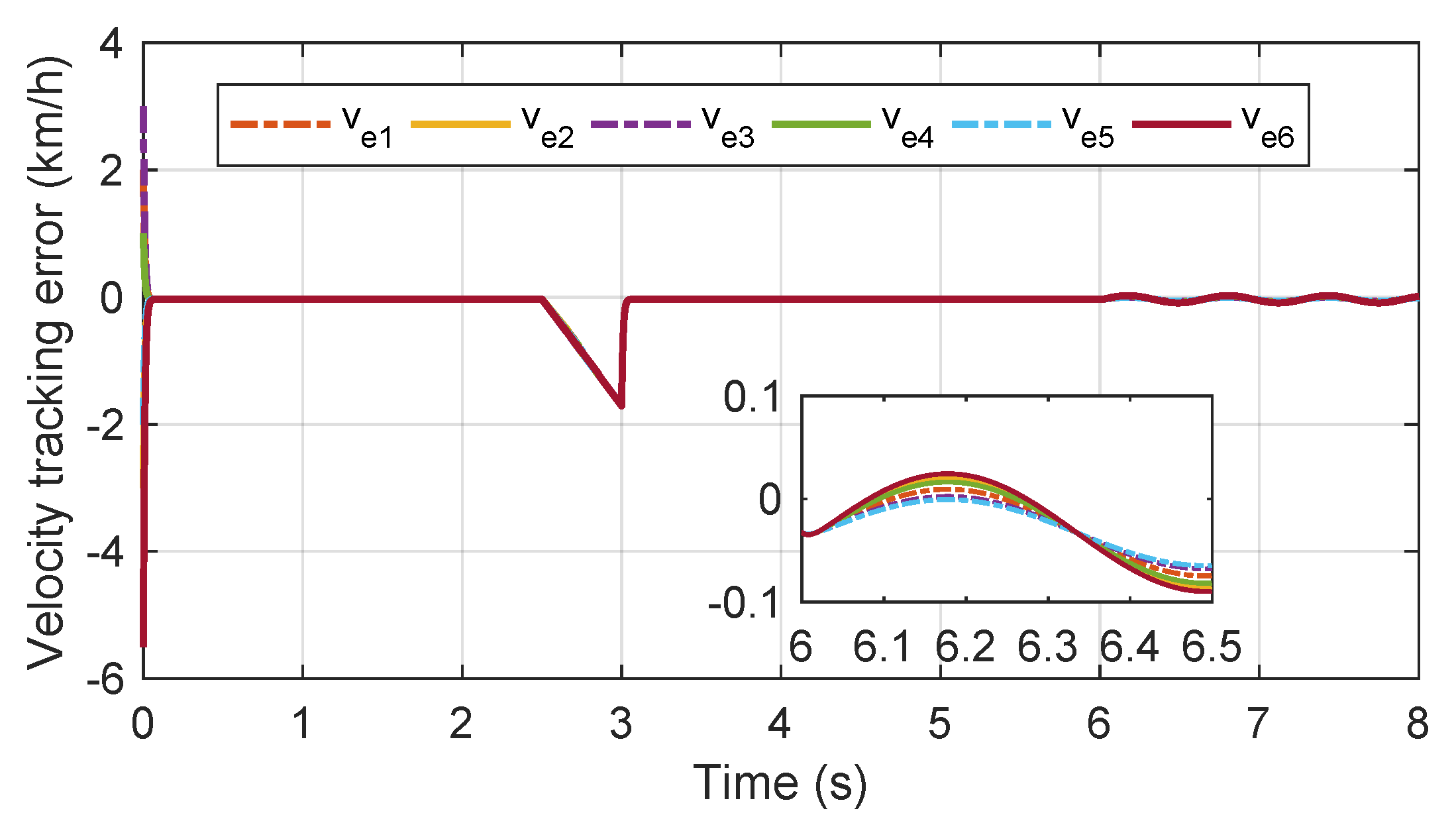
cm. The velocity tracking error curves in case 1 are plotted in 
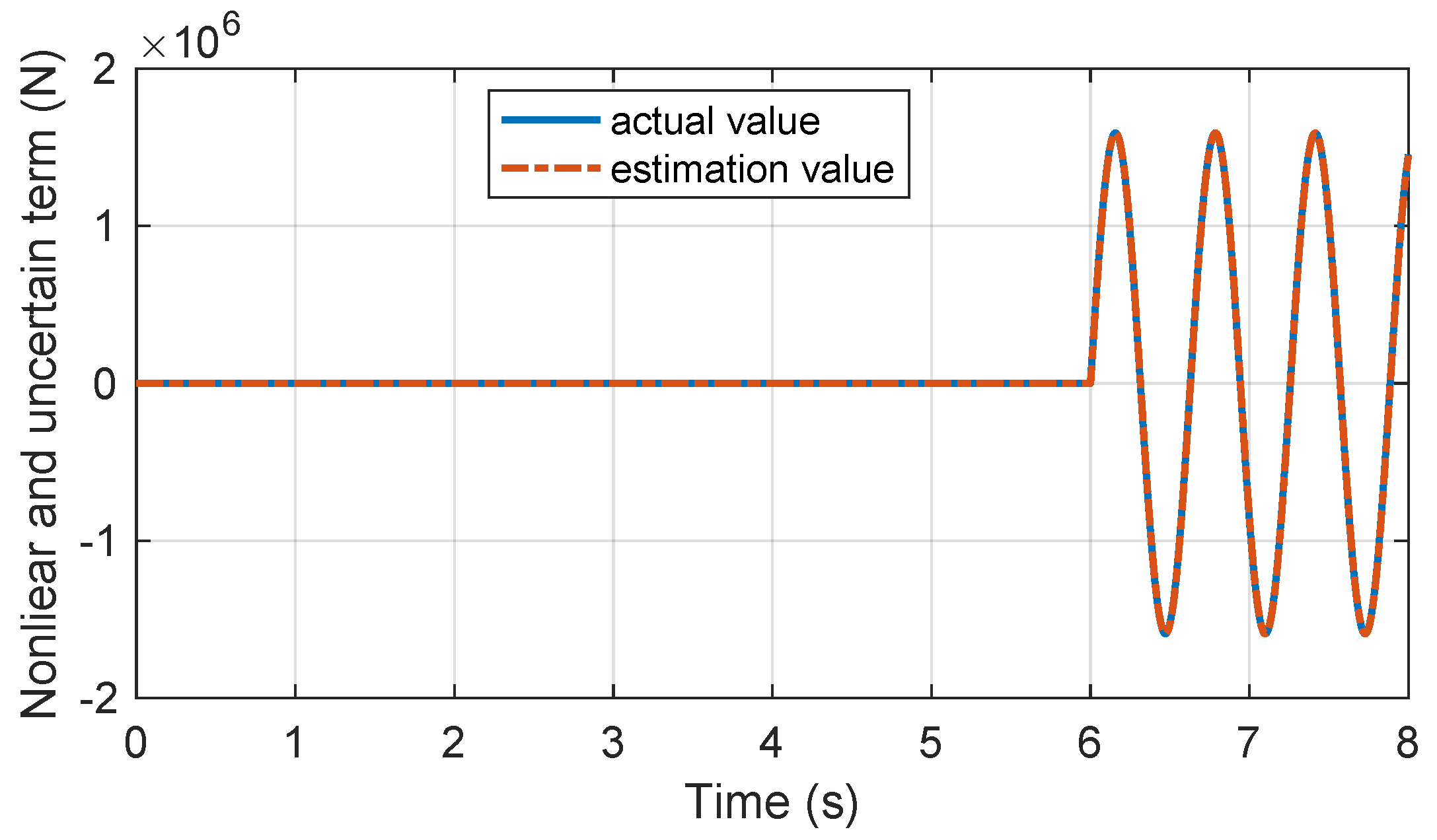
Figure 5. It can be seen from this figure that the proposed consensus braking control strategy can ensure the velocity tracking error of each carriage rapidly stabilizes around zero. As illustrated in Figure 6, the designed disturbance observer provides precise estimation results about the non-linear coupling force of carriage 2 in case 1. The estimation value can converge to the actual value within 20 ms.
  • Case 2: Poor railway condition and no external disturbances.
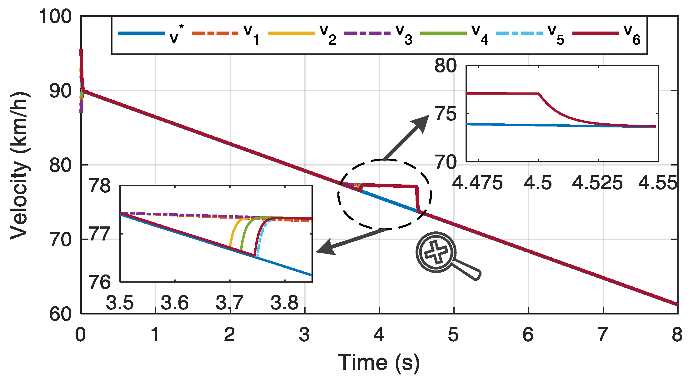
Each carriage of an urban railway train has sufficient braking capacity to achieve the desired braking demand when the railway condition is fine. However, when the railway condition deteriorates, especially for emergency braking, each carriage of the urban railway train may encounter a different sliding level. It means that the braking capacity will also decline. Under this circumstance, the braking control system of each carriage will employ anti-skid controls to ensure braking safety. These actions will cause the phenomenon that the velocity of each carriage is inconsistent. To further verify the performance of the proposed consensus braking control strategy, the railway condition of each carriage is deteriorated, respectively, when t = 3.5 s, and each carriage is set under different railway conditions. Further, to make the testing effect more obvious, after 1 s of skidding, the adhesion control is only employed to restore the braking capacity of each carriage.
Figure 7 describes the velocity curve of each carriage in this simulation scenario. Although the velocity of each carriage is inconsistent at the initial stage, the velocity of each carriage rapidly converges to the consensus target value under the action of the proposed braking control strategy. As shown in Figure 7, the railway condition deteriorated at 3.5 s. In this case, each carriage is configured under different rail conditions, and the braking capacity of each carriage is different. Then, the velocity of each carriage deviates from the desired value. In this case, carriage 3 encounters the highest sliding level, which indicates that carriage 3 has the least effective braking force. To prevent the velocity differences from increasing further, the velocities of the other carriages converge to the velocity of carriage 3 successively under the action of the proposed consensus braking controller.
Then, when the braking capacity is recovered, the proposed consensus braking control strategy can make each carriage quickly converge to the virtual reference velocity within a short time of about 0.03 s, ensuring the braking capacity of the whole train. Therefore, it can be clearly seen that the developed consensus braking control strategy ensures that each carriage can achieve the consensus braking behaviour and maintain the train braking capacity as far as possible. Furthermore, according to the above analysis, the proposed controller can make the velocity of each carriage converge to the desired value from different initial velocity levels.
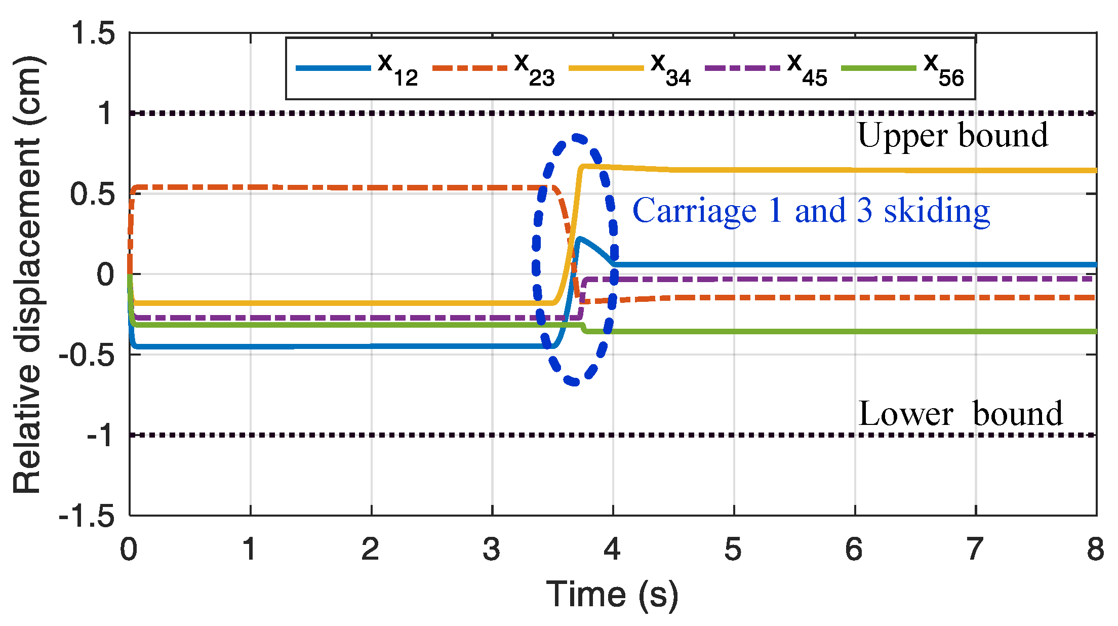
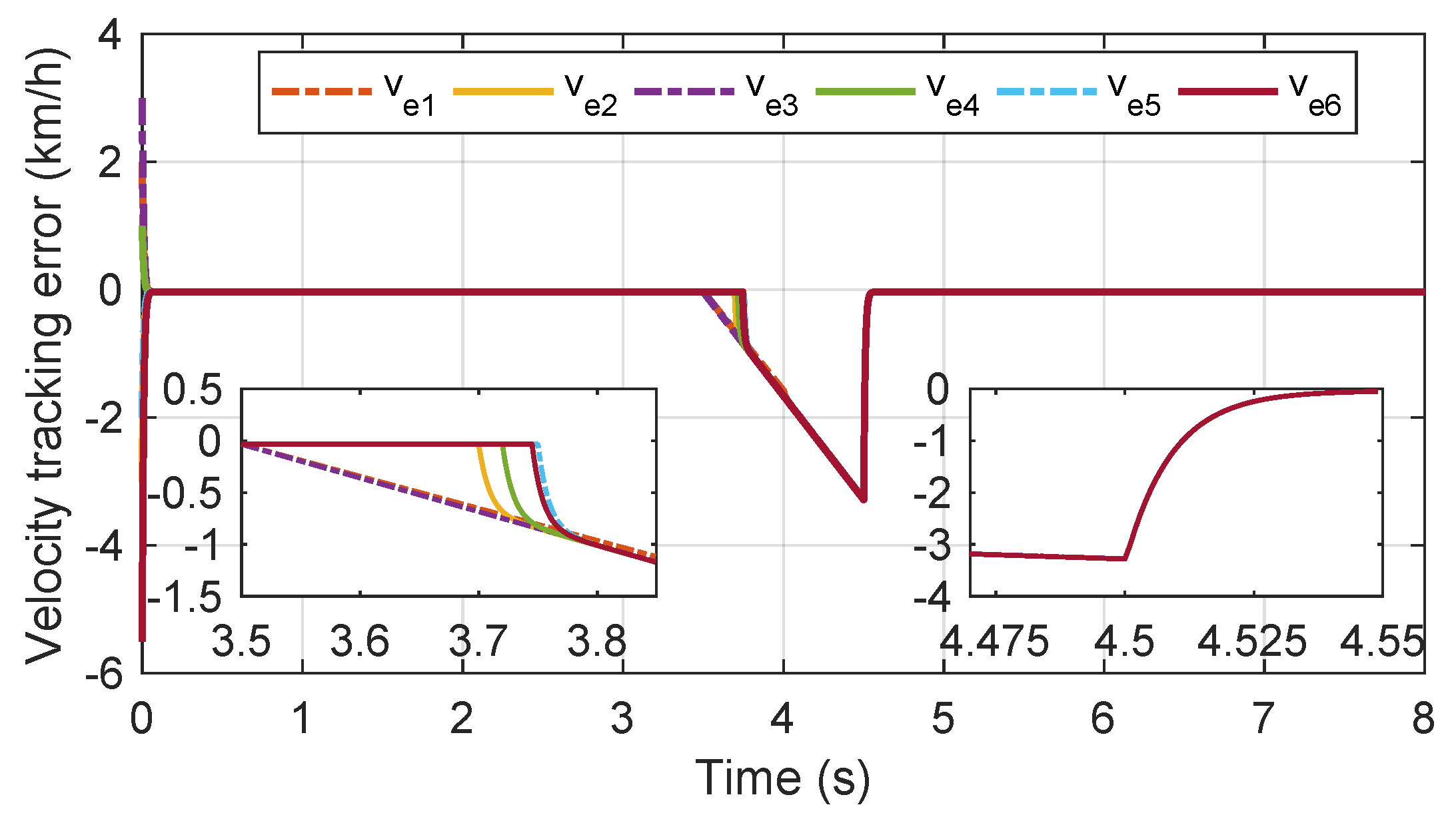
Figure 8 illustrates the relative displacements between adjacent carriages in case 2. In this simulation scenario, both carriages 1 and 3 encounter high skidding due to deterioration of railway conditions so that the relative displacements between carriages 1 and 2, carriages 2 and 3, and carriages 3 and 4 change obviously. Moreover, the proposed control strategy can ensure that these relative displacements always remain within the prescribed safety range. The velocity tracking errors are presented in Figure 9. It is worth noting that both carriages 1 and 3 cannot track the desired reference velocity due to the decrease in braking capacity, and other carriages should converge to the velocity of carriage 3 to ensure velocity consistency. Until the braking capacity of carriage 3 is recovered, all velocity tracking errors relative to the virtual reference velocity uniformly converge to around zero. 
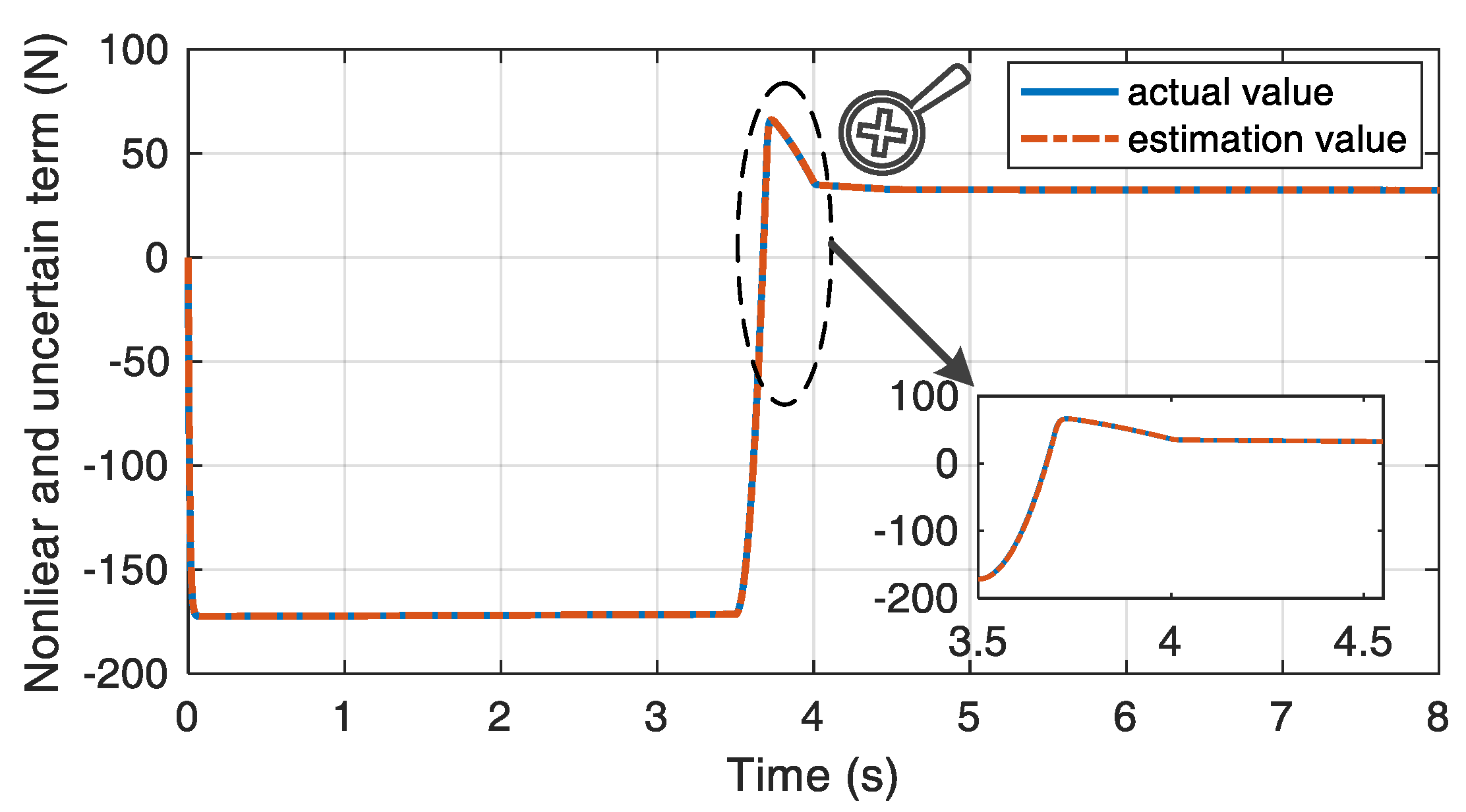
Figure 10 presents the estimation result for carriage 2 in case 2.
  • Case 3: Poor railway condition and existing external disturbance.
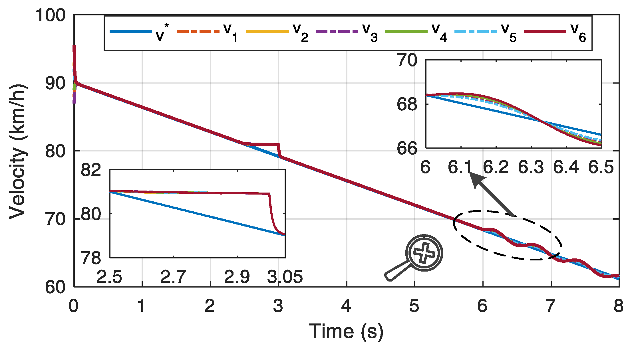
In practical applications, urban railway vehicles have to encounter various external disturbances. Thus, it is necessary to verify the performance of the proposed control strategy under uncertain external disturbances. In this simulation scenario, the sinusoidal disturbance signal is adopted to simulate the uncertain external disturbances, and more serious deteriorations of railway conditions are carried out at t = 2.5 s. Furthermore, comparative simulation tests are conducted to verify the effectiveness of the developed observer-driven consensus braking controller.
Figure 11 provides the velocity curve of each carriage without the anti-disturbance compensation control part in case 3. At t = 2.5 
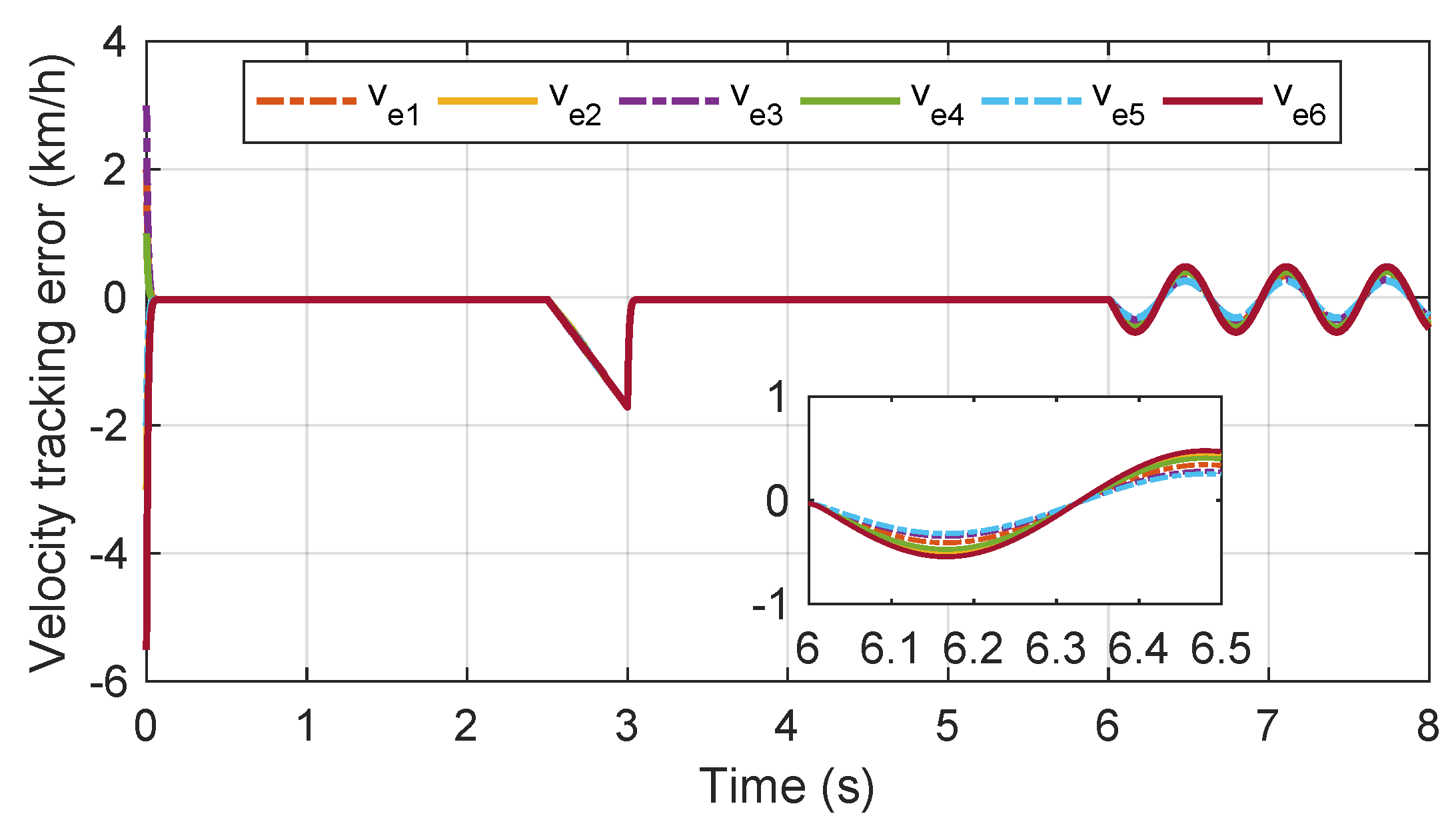
s, all carriages suffer a lack of braking capacity and are unable to continue tracking the virtual reference velocity. To ensure that the velocity of each carriage is consistent with that of its neighbour node, carriages gradually converge to the velocity of carriage 3, which has the most braking capacity loss similar to case 2. After the railway vehicle runs for 6 s, the uncertain external disturbance is employed. Then, the velocity-tracking performance of each carriage deteriorates due to the absence of compensation from the disturbance observer. As shown in Figure 12, the amplitude of the speed tracking error appears as frequent oscillations. This phenomenon will reduce the driving comfort and braking accuracy of the urban railway vehicle.
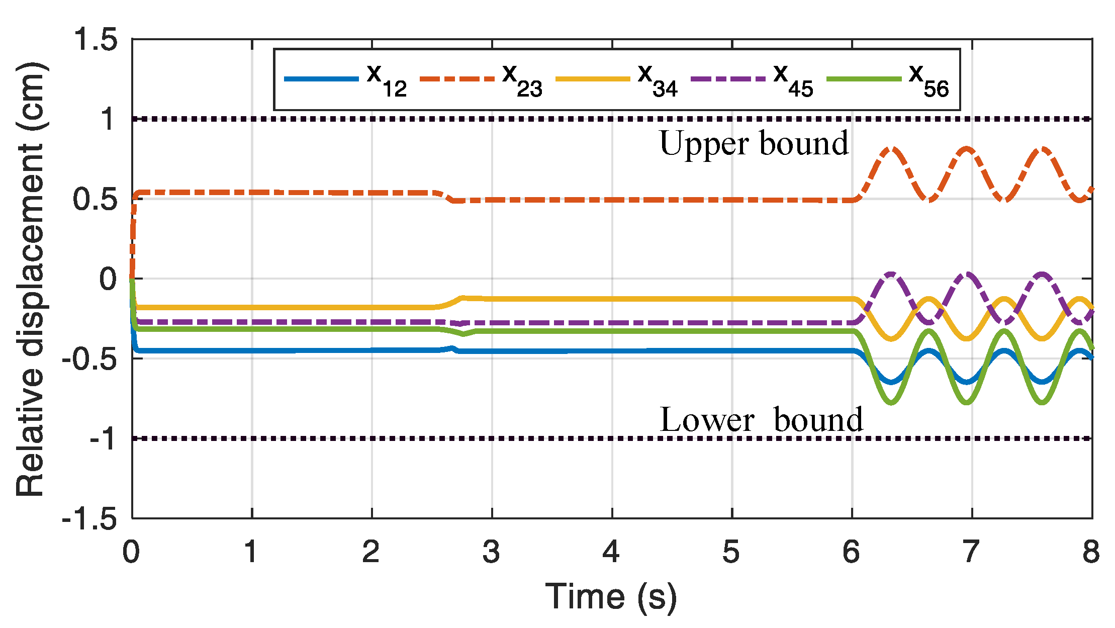
Figure 13 presents the relative displacement curves of each carriage without the anti-disturbance compensation control part in case 3. When all carriages skid, the proposed consensus braking control strategy can ensure that the relative displacement of each carriage does not significantly change and remains within the range of the safety constraints. However, although the relative displacement of each carriage still meets the safety constraints, deterioration will inevitably occur after the external disturbance is employed at t = 6 s.
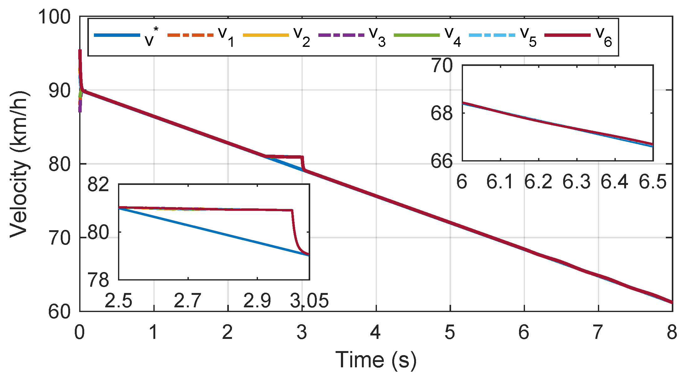
The disturbance-observer-driven consensus braking control strategy is re-applied to the urban railway vehicle braking control system. Figure 14 presents the velocity curve of each carriage with the proposed observer-driven consensus braking control strategy in case 3. As illustrated in Figure 14 and Figure 15, the designed anti-disturbance compensation control part makes the velocity tracking error of each carriage remain within a small range. The velocity of each carriage can converge to the consensus target in a short time. The braking performance and driving comfort of the urban railway vehicle with the proposed disturbance-observer-driven consensus braking control strategy can be guaranteed under various external disturbances.
The relative displacement curve of each carriage with the proposed observer-driven consensus braking control strategy is presented in Figure 16. The relative displacement between adjacent carriages does not significantly change, always within the range of safety constraints. Figure 17 presents the designed disturbance observer’s estimation result for carriage 2 in case 3. The comparative simulation results validate that the developed observer-driven consensus braking control strategy can significantly ensure braking performance under uncertain external disturbances. The effectiveness of the proposed method is again validated.

5. Conclusions

In this paper, a novel disturbance-observer-driven distributed consensus braking control strategy is proposed for urban railway vehicles, ensuring the velocity consistency and relative displacements between any adjacent carriages always remaining within a safety constraint. To address the inherent non-linearities and external disturbances, the sliding-mode observer-based anti-disturbance compensation control is developed, where the estimation value is fed back into the system input to implement active compensation. Further, the potential field function is introduced in the consensus controller design to strictly ensure train operation safety. The proposed cooperative braking controller is demonstrated to rapidly stabilize the velocity of each carriage close to the desired consensus value, thus ensuring the braking performance. Extensive simulation results indicate the effectiveness and feasibility of the proposed method in various operational scenarios. At present, the non-linearities and uncertainties of train braking systems are addressed in this paper. Future work will explore the development of the cooperative train braking controller by further considering the communication delay among carriages.

Author Contributions

Conceptualization, B.C. and W.D.; methodology, B.C. and R.Z.; software, B.C.; validation, F.Z.; formal analysis, B.C.; investigation, R.Z.; resources, W.D.; data curation, B.C.; writing—original draft preparation, B.C. and F.Z.; writing—review and editing, B.C. and R.Z.; visualization, B.C. and R.Z.; supervision, F.Z.; project administration, W.D.; funding acquisition, F.Z. All authors have read and agreed to the published version of the manuscript.

Funding

This research were funded by the General Project of Hunan Natural Science Foundation (2021JJ30876, 2021JJ30868).

Conflicts of Interest

The authors declare no conflict of interest.

References

  1. Yang, X.; Li, X.; Ning, B.; Tang, T. A survey on energy-efficient train operation for urban rail transit. IEEE Trans. Intell. Transp. Syst. 2015, 17, 2–13. [Google Scholar] [CrossRef]
  2. Picasso, B.; Caporale, D.; Colaneri, P. Braking control in railway vehicles: A distributed preview approach. IEEE Trans. Autom. Control. 2017, 63, 189–195. [Google Scholar] [CrossRef]
  3. Chen, D.; Chen, R.; Li, Y.; Tang, T. Online learning algorithms for train automatic stop control using precise location data of balises. IEEE Trans. Intell. Transp. Syst. 2013, 14, 1526–1535. [Google Scholar] [CrossRef]
  4. Aguiar, B.; Berdjag, D.; Demaya, B.; Guerra, T.M. A robust and fault tolerant approach for automatic train stop control system design. IFAC-Paper 2017, 50, 8549–8554. [Google Scholar] [CrossRef]
  5. Zhang, R.; Peng, J.; Zhou, F.; Chen, B.; Liu, W.; Huang, Z. Adaptive precision automatic train stop control based on pneumatic brake systems. In Proceedings of the IECON 2019-45th Annual Conference of the IEEE Industrial Electronics Society, Lisbon, Portugal, 14–17 October 2019; Volume 1, pp. 273–278. [Google Scholar]
  6. Wang, Q.; Chai, M.; Liu, H.; Tang, T. Optimized control of virtual coupling at junctions: A cooperative game-based approach. Actuators 2021, 10, 207. [Google Scholar] [CrossRef]
  7. Wang, X.; Tang, T.; He, H. Optimal control of heavy haul train based on approximate dynamic programming. Adv. Mech. Eng. 2017, 9, 1687814017698110. [Google Scholar] [CrossRef] [Green Version]
  8. Gao, D.; Peng, J.; Peng, H.; Chen, B.; Huang, Z. Cooperative braking of urban rail vehicles with Koopman model predictive control. IET Control. Theory Appl. 2022, 1, 1–12. [Google Scholar] [CrossRef]
  9. Zheng, Y.; Zhu, Y.; Wang, L. Consensus of heterogeneous multi-agent systems. IET Control. Theory Appl. 2011, 5, 1881–1888. [Google Scholar] [CrossRef]
  10. Zhao, F.; Liu, Y.; Wang, J.; Wang, L. Distributed Model Predictive Longitudinal Control for a Connected Autonomous Vehicle Platoon with Dynamic Information Flow Topology. Actuators 2021, 10, 204. [Google Scholar] [CrossRef]
  11. Li, S.; Yang, L.; Gao, Z. Coordinated cruise control for high-speed train movements based on a multi-agent model. Transp. Res. Part Emerg. Technol. 2015, 56, 281–292. [Google Scholar] [CrossRef]
  12. Gao, S.; Dong, H.; Ning, B.; Zhang, Q. Cooperative prescribed performance tracking control for multiple high-speed trains in moving block signaling system. IEEE Trans. Intell. Transp. Syst. 2019, 20, 2740–2749. [Google Scholar] [CrossRef]
  13. Wang, Y.; Song, Y.; Gao, H.; Lewis, F.L. Distributed fault-tolerant control of virtually and physically interconnected systems with application to high-speed trains under traction/braking failures. IEEE Trans. Intell. Transp. Syst. 2015, 17, 535–545. [Google Scholar] [CrossRef]
  14. Zhao, Y.; Wang, T. Distributed control for high-speed trains movements. In Proceedings of the 2017 29th Chinese Control and Decision Conference (CCDC), Chongqing, China, 28–30 May 2017; pp. 7591–7596. [Google Scholar]
  15. Bai, W.; Lin, Z.; Dong, H.; Ning, B. Distributed Cooperative Control of a High-speed Train. In Proceedings of the 2019 American Control Conference (ACC), Philadelphia, PA, USA, 10–12 July 2019; pp. 2716–2721. [Google Scholar]
  16. Wang, W.; Le, J.; Wang, Z.; Luo, X.; Kurths, J.; Yuan, M.; Ma, Y. Event-Triggered Consensus Control for High-Speed Train with Time-Varying Actuator Fault. IEEE Access 2020, 8, 50553–50564. [Google Scholar] [CrossRef]
  17. Chaudhari, S.; Shendge, P.; Phadke, S.B. Dynamic Nonlinear Gradient Observer based Extremum Seeking Control for Optimum Braking. IEEE Trans. Ind. Electron. 2021, 69, 2833–2842. [Google Scholar] [CrossRef]
  18. Ginoya, D.L.; Patel, T.R.; Shendge, P.; Phadke, S. Design and hardware implementation of model following sliding mode control with inertial delay observer for uncertain systems. In Proceedings of the 2011 3rd International Conference on Electronics Computer Technology, Kanyakumari, India, 8–10 April 2011; Volume 3, pp. 192–196. [Google Scholar]
  19. Chen, B.; Huang, Z.; Zhang, R.; Jiang, F.; Liu, W.; Li, H.; Wang, J.; Peng, J. Adaptive slip ratio estimation for active braking control of high-speed trains. ISA Trans. 2021, 112, 302–314. [Google Scholar] [CrossRef] [PubMed]
  20. Jing, C.; Xu, H.; Niu, X. Adaptive sliding mode disturbance rejection control with prescribed performance for robotic manipulators. ISA Trans. 2019, 91, 41–51. [Google Scholar] [CrossRef] [PubMed]
  21. Patil, A.; Ginoya, D.; Shendge, P.; Phadke, S. Uncertainty-estimation-based approach to antilock braking systems. IEEE Trans. Veh. Technol. 2015, 65, 1171–1185. [Google Scholar] [CrossRef]
  22. Kim, N.; Oh, D.; Oh, J.Y.; Lee, W. Disturbance-Observer-Based Dual-Position Feedback Controller for Precision Control of an Industrial Robot Arm. Actuators 2022, 11, 375. [Google Scholar] [CrossRef]
  23. Garg, V. Dynamics of Railway Vehicle Systems; Academic Press: Toronto, ON, Canada, 1984. [Google Scholar]
  24. Wang, X.; Li, S.; Tang, T. Robust optimal predictive control of heavy haul train under imperfect communication. ISA Trans. 2019, 91, 52–65. [Google Scholar] [CrossRef] [PubMed]
Figure 1. The dynamics of an urban railway train during braking.
Actuators 12 00111 g001
Figure 2. Proposed observer-driven distributed consensus braking control approach for an urban railway train.
Actuators 12 00111 g002
Figure 3. Velocity curve of each carriage with the proposed consensus braking controller in case 1.
Actuators 12 00111 g003
Figure 4. Relative displacement curve of each carriage with the proposed consensus braking controller in case 1.
Actuators 12 00111 g004
Figure 5. Velocity tracking error curve of each carriage with the proposed consensus braking controller in case 1.
Actuators 12 00111 g005
Figure 6. Estimation result for carriage 2 with the designed disturbance observer in case 1.
Actuators 12 00111 g006
Figure 7. Velocity curve of each carriage with the proposed consensus braking controller in case 2.
Actuators 12 00111 g007
Figure 8. Relative displacement curve of each carriage with the proposed consensus braking controller in case 2.
Actuators 12 00111 g008
Figure 9. Velocity tracking error curve of each carriage with the proposed consensus braking controller in case 2.
Actuators 12 00111 g009
Figure 10. Estimation result for carriage 2 with the designed disturbance observer in case 2.
Actuators 12 00111 g010
Figure 11. Velocity curve of each carriage without the anti-disturbance control component in case 3.
Actuators 12 00111 g011
Figure 12. Velocity tracking error curve of each carriage without the anti-disturbance control component in case 3.
Actuators 12 00111 g012
Figure 13. Relative displacement curves of each carriage without the anti-disturbance control component in case 3.
Actuators 12 00111 g013
Figure 14. Velocity curve of each carriage with the proposed observer-driven consensus braking control strategy in case 3.
Actuators 12 00111 g014
Figure 15. Velocity tracking error curve of each carriage with the proposed observer-driven consensus braking control strategy in case 3.
Actuators 12 00111 g015
Figure 16. Relative displacement curve of each carriage with the proposed observer-driven consensus braking control strategy in case 3.
Actuators 12 00111 g016
Figure 17. Estimation result for carriage 2 with the designed disturbance observer in case 3.
Actuators 12 00111 g017
Table 1. Nomenclature.
SymbolDefinition
x i The displacement carriage i
v i The velocity of carriage i
f i The total resistance of carriage i
F a i The actual braking force of carriage i
Δ l i The coupler’s deformation length between carriage i and carriage i + 1
Φ i The coupling force between carriage i and carriage i + 1
l 0 The original length of the coupling spring
κ i , ϵ i The elastic coefficients of the coupling spring i
m i The mass of carriage i
u i The braking control input of carriage i
K b i The braking coefficient of carriage i
f r i The running resistance of carriage i
f c i The additional resistance of carriage i
θ c i The track slope angle
D c i The curvature degree
A a The weighted adjacency matrix about the velocity data interaction
A b The weighted adjacency matrix about the displacement data interaction
D a The degree matrix about the velocity data interaction
D b The degree matrix about the displacement data interaction
L a , L b The Laplacian matrices
θ 1 The lower bound of the relative displacement
θ 2 The upper bound of the relative displacement
v The desired velocity
a r The desired deceleration
v e i The velocity tracking error
Table 2. Main simulation parameters of the observer-driven distributed consensus braking controller for urban railway trains.
ParametersValues
n6
κ i 80,000 N/m
ϵ i 0.5
m i [18,000, 21,000, 19,500, 20,000, 19,700, 22,000] kg
v i ( t 0 ) 88 , 93 , 87 , 89 , 92 , 95.5 km/h
x i ( t 0 ) 10 , 20 , 30 , 40 , 50 , 60 m
α 1 , α 2 120 , 100
k i 36
k d i 50
δ 2
θ 1 1 cm
θ 2 1 cm
Disclaimer/Publisher’s Note: The statements, opinions and data contained in all publications are solely those of the individual author(s) and contributor(s) and not of MDPI and/or the editor(s). MDPI and/or the editor(s) disclaim responsibility for any injury to people or property resulting from any ideas, methods, instructions or products referred to in the content.

