1. Introduction
The built building, as a rule, has deviations from the project, according to which the calculation was carried out. The accumulation of geodesic errors, due to which the nodes of the structure have a deviation from the design position in space, the change in forces during the construction of the building, the deviation of the mechanical characteristics of the structural elements when violating the technological process of construction and other events can cause these defects. The traditional methodology of analyzing new design schemes of a structure requires considerable effort to recalculate the structure. We are not interested in the distribution of forces in the entire structure, but only in the most stressed elements and sections during recalculation.
What is needed is a method of finding the forces for the new calculation scheme that would indicate where the unsafe cross-sections are, in which the limiting state will arise in the first place with a small cost of calculating the internal forces.
The theory of elastoplastic analysis could be one of the approaches [
1,
2,
3,
4,
5,
6,
7]. This is the most developed theory of successive elimination of structural connections due to reaching the limit state in the plastic stage of material deformation. Computational models are formulated for different kinds of stressed states of beams, frames, plates and shells, and theorems about the conditions of the limit state approach in the structure are proved.
There are two criteria generating the research methodology and leading to the same result.
The static criterion is based on the consideration of all possible stress states of the structure. The solution to the problem is considered to be the stressed state of the structure, at which the maximum intensity of external loads does not exceed the limit values, which are balanced by the internal efforts in the elements of the structure.
According to the kinematic method, it is necessary to assume that so many elements have entered the state of fluidity that the system has become geometrically changeable (turned into a kinematic chain). Of all the calculated values of the limit loads, the true value will be the lowest value at which the system becomes geometrically changeable.
Sequential application of the methodology could lead to the desired result. However, it reduces the whole set of problem LSDs (limit state designs) about the limit states of structures to only one of them. In addition, the result for one type of loading is obtained. While it is necessary to have a conclusion about the limit states for as many loads of the structure as possible.
Another theory that requires a similar methodology is the calculation for progressive collapse [
8,
9,
10,
11,
12,
13,
14,
15,
16,
17,
18,
19,
20,
21,
22,
23,
24,
25,
26]. Regulatory documents of many countries require the analysis of the erected structure for the successive disabling of structural elements that have been subjected to accidental or beyond design effects. A large number of possible acting and collapse variants make it necessary to use concepts that simplify the task. Such as the “tying force” clause, which is considered sufficient to prevent disproportionate collapse; the “conditional element removal” provisions, if the previous requirement is not met; or the “key element” clause, applied to elements whose conditional removal causes damage that exceeds the specified limits.
Other techniques are based on the removal of a single column from the first floor above the first floor of the building. The static analysis of the building structure is done with the column removal criteria in mind. According to these criteria, a column is removed for typical structures: an exterior column in the middle of the long side of the building; an exterior column in the middle of the shorter side of the building; a corner column.
Methods of Linear dynamic (Response spectrum) analysis combined with Nonlinear static analysis are widely used.
There are optimizations and other methods for evaluating trusses’ internal forces presented in [
27,
28,
29,
30].
The presence of such a large number of progressive collapse techniques indicates that the structure models and theory are underdeveloped. The biggest disadvantage is the impossibility to take into account all types of limiting states of structures, and the need to recalculate the different types of design models of the structure.
Obviously, the proposed methods have one goal—to find the elements in which the limit state will occur, so that they can be taken out of service on the current load.
The proposed approach uses the concept of progressive limiting state (failure) as a successive withdrawal of structural elements from operation under load due to the onset of the limiting state in them. The type of limit state is not specified, because the elements (bonds) are removed from the load at the time of its occurrence, and the designer can use the one that corresponds to the phenomenon in the study.
The limit state is realized at critical levels of the internal potential energy of the structure [
31,
32]. The distribution of internal forces in the system elements will change in a similar way until the moment of passing through the critical level of the potential energy of deformation of the system. The methodology for investigating the progressive limiting state of structures is reduced to determining the internal forces (displacements) in the elements of the deformed system when varying the main vector of generalized displacements (reactive forces of the system) applied in its nodes [
31,
32]. When crossing the critical level, the bonds in the most stressed element will be removed, which will entail a change in the design scheme or a change in the form of deformation. The process of removing ties will last until the system becomes an unstable structure.
The implementation of the technique gives the designer the opportunity to predict the possible design patterns and forms of deformation of the system in the successive onset of the limit state in its elements.
2. Methods
Let us present the problem of determining the displacements of the structure in the form of the stiffness method.
Here is the stiffness matrix of the structure; is the vector of generalized displacements of the system; is the vector of generalized reactions in the nodes of the system from external actions.
The expression written in the form (1) can be interpreted as the equality of reactions in the fictitious bonds caused by internal forces and external loads. Since we do not stipulate the magnitude of the external load in advance when deriving the equations of the displacement method, condition (1) is satisfied for any loads, including unit and zero loads. In the latter case, in addition to the zero vector of nodal displacements, there may be nonzero displacements for the case of self-stressing of the system. In other words, at all loading levels of the structure, the redistribution of node displacements takes place in accordance with the stiffnesses of our chosen nodes of the system, as in the case of self-stressing.
This condition can be written by analogy with the expression obtained in [
31], as a variation of possible displacements in the nodes of the system
here,
is the eigenvalues of the stiffness matrix caused by nodes displacements variation. The eigenvalues
is the main values of the nodal reactions of the system, and the eigenvectors
are the amplitude values of the node displacements of the trusses self-stress state.
The physical meaning of the derived Equation (2) is the state of self-stress in a statically indeterminate system at critical energy levels. The solution of the eigenvalue problem gives the main values of the reactions of the nodes of the structure and the corresponding vectors of amplitude values of the node displacements. At each critical energy level, starting from the first, and further, when the bonds that were in the limiting state are removed, the self-stress state of the structure will also change. However, at each critical energy level, the self-stress state will satisfy condition (2). For the extremal nodal forces, we have equality
where
includes minimum and maximum values and other possible nodal reactions of the structure.
The physical meaning of the proposed methodology can be explained through the concept of the primary structure (simple statically determinate structure) of a statically indeterminate problem. It is known that the primary structure of a statically indeterminate problem can be any statically determinate or statically indeterminate structure, including a given structure model. The number of primary structures of a statically indeterminate problem can be an infinite number. The choice of the primary structure in the force method, stiffness method or any other method does not influence the final result of the solution of the problem.
It follows on from the mathematical model of problem (1) that changes in the right part (application nodes, type of loading and its magnitude) result in a new value of forces and deformation distribution in the structural rods. That is why there is an infinite number of variants for the limit state approach in the elements of the structure. The problem of sequential reaching of the limit state in the structural rods becomes very complicated.
As it is known from the theory of eigenvalue problems, for any symmetric matrix it is possible to specify such an eigenvector, the components of which change proportionally to the eigenvalues in a similar way. In our case, this will be such a primary structure of the statically indeterminate problem for which the reactive response (nodal reactions or displacements) to external actions will change in proportion to the eigenvalues of the matrix in expression (2). Or the internal forces and deformations of the rods will change in proportion to the eigenvalues, and the distribution of forces (deformations) in the rods will change in a similar way. This type of stress state will not depend on the application nodes, the magnitude and types of the external loads.
Presenting the external node influences in the normalized form (unitary), it is possible to construct a method of finding the successive exit of the bars from the work under the actions due to the onset of the limit state in them.
Some known relations from structural mechanics presented in matrix form will formulate the algorithm for finding the “weak link” in the structure as follows.
We construct a matrix stiffness coefficient (internal stiffness matrix) of the system .
Then, using the equations of equilibrium of the nodes of the structure, we construct a static matrix .
The structure stiffness matrix is calculated as
We solve the eigenvalue problem for the stiffness matrix. The solution for the eigenvalue problem (2) will reveal the state of the system with minimal stiffness and the corresponding eigenvector of generalized displacements.
The generalized reactive forces of the system nodes are obtained according to (3) by multiplying the minimal eigenvalue by the corresponding eigenvector. Then forces and strains in the rods we get as
If we use the force method task statement, we should calculate the flexibility matrix of the structure .
For the structure’s flexibility matrix, we calculate the principal directions of the nodal displacement vectors by multiplying eigenvalues
by the eigenvectors
The vectors of nodal reactions and displacements of the structure normalized by the maximum value coincide with the accuracy of a sign.
The node vectors of the structural reaction to external actions (7) cause the maximum values of internal forces or strains of the structural rods.
The strains of the rods are determined by the principal nodal displacements
The calculation of the internal forces in the rods of the system is carried out by the strains
The normalized values of the vectors of internal forces and strains, determined by the force method and the stiffness method, are the same
The limit state condition may be presented in rod stresses, or in rod strains. If they are disturbed, the rod, in which this has occurred, must be “removed”, because it has ceased to work for the load. And the analysis of the new design scheme of the structure should be proceeded with. Before the calculation, we check the geometrical stability of the system at each stage by the condition
If the limit state is given through the strain limit, remove the rod with exceeding the strain limits found by (5) or (8). If the limit conditions are written in stresses, they are calculated from the forces in the rods (5) or (9).
In the case of several types of limit states, we remove the rod with extreme values of forces and deformations according to the conditions of the problem.
We continue solving according to the algorithm until we obtain a statically determined system. The condition for the loss of the load-carrying capacity is the transformation of the structure into a geometrically changeable structure.
Using the obtained normalized values of the limit loads, summed over all the stages, we find the values of the limit loads on the system.
Analysis of the values of the limit loads in the nodes of the system, allows you to build a map of allowable loads in the nodes of the structure, which will show the values of the projections of the limit loads in the horizontal and vertical directions [
31].
3. Results
The occurrence of the limit state in the structural rods can happen in two main cases:
- (1)
The accumulation of defects in the structural rods, errors in the construction of the structure, improper operation of the structure;
- (2)
Accidental loads, explosions and removal of connections.
3.1. Example 1. Determination of the Weak Link of a Structure under Case 1 Actions
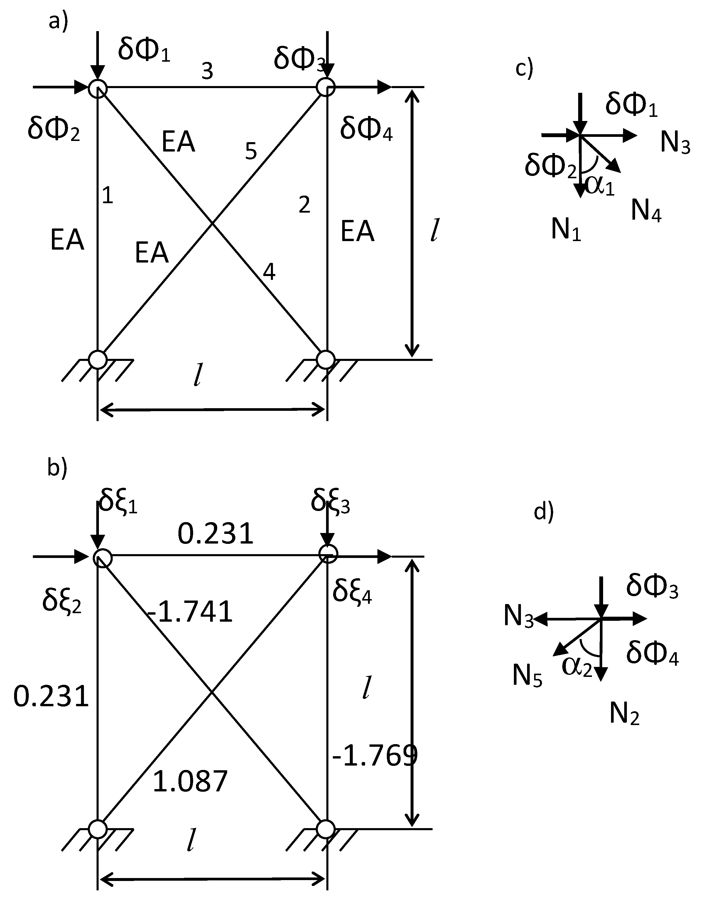
Consider a plane truss with redundancies shown in
Figure 1. The initial arbitrarily chosen degrees of freedom (DOF) are shown in
Figure 1a to solve the problem by the force method [
32], where the generalized reactions in the nodes
of the structure are varied. The stiffness method DOF is shown in
Figure 1b, where the generalized displacements in the nodes
of the structure are varied.
We take the stiffnesses of the rods as the same, and the displacements or reactions in the structure nodes are the same as the direction of DOF. The stiffnesses and numbers of the rods, as well as the geometric sizes, are shown in
Figure 1a.
The diagrams of the forces in the rods from the reactions in nodes cut out from the system necessary to compose the equations of equilibrium are shown in
Figure 1a,b. For the left node, we have
The static matrix, based on the equations of equilibrium of the nodes, has the form
The matrix of stiffness coefficients of the structure has the form
where the lengths of the inclined rods are equal to
,
—cross-sectional area of the rod,
—Young’s modulus.
The structure stiffness matrix calculated by (4) and has the form
The matrix of eigenvalues obtained for the flexibility matrix is written
The eigenvectors matrix for the flexibility matrix has the form
What is the physical meaning of these results? We have found the values of the nodal reactions of the construction and their directions in the Cartesian coordinate system. This is the main self-balanced (self-stressed) state of the construction.
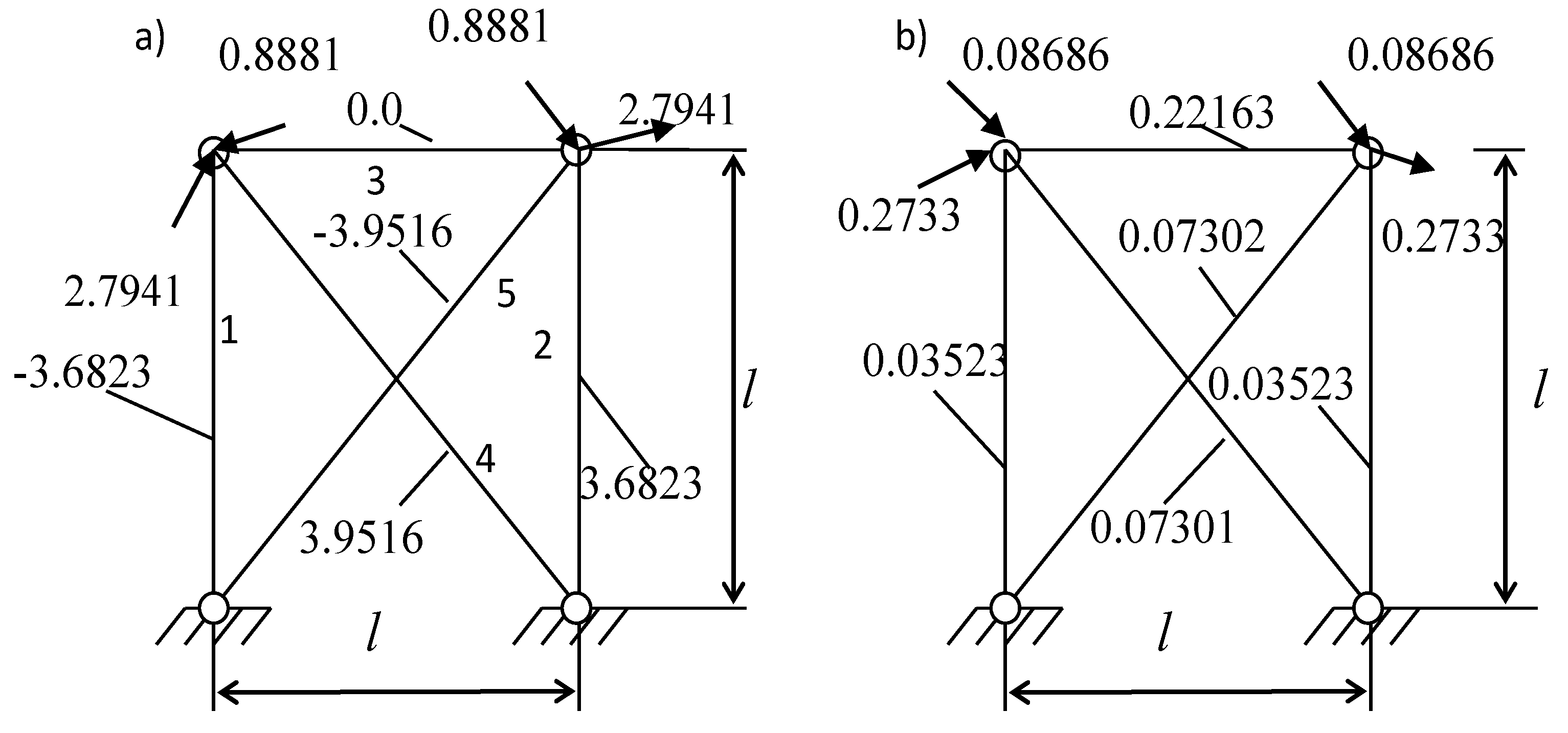
We may calculate force distribution in the rod structure. Rod forces will change by the same proportion until the construction loses one (or several) of the rods. The forces in the rods are shown in
Figure 1b, where the numerical values of the forces are placed next to the rods.
It is obvious that there may be displacements (reactions) directions, which correspond to the maximum (minimum) values of the structure’s flexibility (stiffness). Maximum (a) and minimum (b) forces in the truss rods and directions of structure reactions corresponding to the eigenvectors of the problem are shown in
Figure 2.
Any of the options for the direction of the structure reactive forces (external load) will give rod stress values between the maximum and minimum ones, as shown by numerical studies [
31]. The limit values of forces are achieved in the same rods of the structure under consideration and differ by a normalizing factor.
The service load work in the building structure is compensated for by a portion of the internal potential energy and remains unchanged. The rest of the internal potential energy of the structure is in a self-balanced state, and the possible limit values of the reaction of the structure are limited by the ellipse of limit states [
31]. Possible additional magnitudes of impacts must exceed the value of the vector of limiting reactions of the structure and be applied in the same direction.
If the application nodes and the possible directions of actions are known, we may find out the self-stressed state for it. Then it is possible to determine the element where the stress or displacement limit values will occur.
Returning to the solution of the problem, we assume that all of the nodes have the actions. After finding out the rods’ force, we conclude that the fourth and fifth rods can lose their bearing capacity from the same force, but with different signs. If we assume that the tensile and compressive strengths of the rods are the same, then the limit state can be reached in any of these rods.
Let the limit state come from the loss of stability. Then the fifth rod is the first to be removed at the normalized value of the limiting force .
The second stage considers the system with the fifth rod removed, as shown in
Figure 3.
The matrix of stiffness coefficients of the structure has the form
The structure stiffness matrix calculated by (4)
The matrix of eigenvalues obtained for the flexibility matrix is written
The eigenvectors matrix has the form
As can be seen from
Figure 3, the force distribution for the maximum eigenvalue and the minimum eigenvalue are similar. They differ by the normalization factor, correspondingly to the eigenvalues of the vectors.
Normalized forces in the rods
The forces calculated in the rods show that the most stressed rod is the fifth inclined one with a force of . The ultimate load on the system in two steps was .
3.2. Example 2. Determination of the Weak Link of the Structure When Design Actions Are Exceeded
Consider a truss in which rod 2 was removed as a result of an accident (
Figure 4).
Let us investigate the possible maximum carrying capacity of the truss. To do this, we find the eigenvalues and their corresponding vectors of reactive forces of the truss, as shown in Example 1.
The matrix of stiffness coefficients of the structure has the form
The structure stiffness matrix
The minimum eigenvalue and its corresponding vector are determined by
The main vector of nodal reactions
Normalized vector of internal forces in the rods
The weak link of the structure is the inclined rod with the number four. When rod number four is out of service, the structure becomes geometrically changeable.
We took the same stiffnesses of the rods in this problem for simplicity, so there was no need to calculate the stresses in the rods. We must use stress or strain to investigate any other structure model to verify that the LSD conditions are met.
4. Conclusions
We propose an approach that makes it possible to assess the carrying capacity of the built structure, taking into account the defects that appear in the process of construction, due to technological errors and human factors. In the process of operation, non-design impacts may appear, due to man-made effects or improper operation. In either case, it is necessary to assess the load-carrying capacity of the structures, and the sequence of the exit from work on the load of structural elements is of interest.
An algorithm for determining the most stressed element of the structure called the weakest link, which first of all, will not carry the load.
The matrix formulation of the problem allows us to investigate redundant structures in the form of the stiffness method and force method. The stages of formation of basic matrix relations for problem formulation are shown.
The mathematical model of the problem is an eigenvalue problem. The eigenvalues and eigenvectors allow us to form nodal reaction vectors of the structure with extreme properties. The extreme values of internal forces in the truss rods depend on the vectors of nodal reaction responses of the structure to external actions.
Part of strain energy balancing the work of external forces caused by the design load did not change. The remaining part of the strain energy is investigated to find the weak link. Additional actions on the structure cause forces in its elements, leading to the loss of bearing capacity of the weak link.
The method of calculation is implemented on the example of a redundant truss, for which the sequence of truss rod failure is shown, and the value of the ultimate load is determined.


