Article

Finite Element Analysis of the Bearing Capacity of Beamless Floor Slabs under Punching, Taking into Account the Design Parameters of the Contacting Elements

by
Tatiana Matseevich
Department of Higher Mathematics, National Research Moscow State Civil Engineering University, 26, Yaroslavskoye Shosse, 129337 Moscow, Russia
Buildings 2023, 13(5), 1221; https://doi.org/10.3390/buildings13051221
Submission received: 30 January 2023 / Revised: 20 April 2023 / Accepted: 21 April 2023 / Published: 5 May 2023
(This article belongs to the Special Issue Safety and Optimization of Building Structures)

Abstract

:
Static calculations of experimental models in an elastic formulation were carried out, and the regularities connecting the dependences of forces in the calculated cross-section of punching out from the main structural parameters of contacting elements (reinforced concrete slabs and pylons) and from the used concrete class were revealed. This article concerns the safety issues of reinforced concrete slabs under punching with different ratios and combinations of pylon and slab thickness parameters, as well as concrete strength. The objectives of the research are consideration of the fracture pattern of reinforced concrete monolithic slabs due to punching shear; comparative analysis of modern normative calculation methods and flat reinforced concrete slabs due to static punching shear; finite element modelling and analysis of the punching shear calculation results for reinforced concrete floor slabs; and the force distribution over the area of the contacting elements-saw and floor slab. The practical significance of the results lies in the use of the obtained forces in the contacting elements for the calculation and design of reliable structures of beamless floor slabs.

1. Introduction

1.1. Fracture Behavior of Monolithic Floor Slabs during Punching

Reinforced concrete floor is a responsible structural element of the overall material and structural design of a construction project of any functional purpose, performed in the horizontal plane and intended for (a) dividing the building volume of the capital construction project (flooring); (b) participating in the operation of the load-bearing structural system of the construction project; (c) providing the basis for placing the useful load on the construction project, etc.
Forces exerted on reinforced concrete floor slabs from supporting structures (pylons, columns, walls) often lead to their collapse and even to progressive collapse.
The very phenomenon of the punching shear of reinforced concrete floor slabs without girders is justifiably considered one of the most dangerous in the operation of nodal zones of reinforced concrete slab constructions because of its suddenness.
As a result of analysing such failures, it is possible to identify the main regularities of the impact of the punching shear pressure on reinforced concrete floor slabs:
-
numerous experimental and theoretical studies of the nodal zones of reinforced concrete slabs point to a link between the nature of a node’s performance and the structural design of its reinforcement;
-
stress concentrations from the punching pressure in the load-bearing pylons;
-
pylons are almost always subjected to significant damage when subjected to the punching shear force.
New requirements for the prevention of progressive collapse fully define an increased focus on the reliable functioning of the nodal zones of reinforced concrete slabs.
Based on the characteristic failure of reinforced concrete slabs, it is necessary to investigate the physical picture of the fracture processes and to make an analytical model, allowing the identification of rational methods of reinforcing slab structures and reserves to improve the load-bearing capacity.
The following paper proposes a study of one of the critical aspects of the design of reinforced concrete slabs—the determination of the boundary values of the load-bearing capacity under the impact of the pushing force.

1.2. Analytical Method for the Punching Calculation of Monolithic Reinforced Concrete Floor Slabs

According to [1], the analytical apparatus for the calculation of monolithic reinforced concrete floor slabs is determined from the equilibrium conditions of the resultant forces on the allocated flat element (see Figure 1).
In order to provide an acceptable approximation of the real working conditions, the selected unit volume of the concrete element is divided into a number of layers or plates (Figure 2), on which the normal forces (N), transverse forces (Q), bending moments (Mx, My), and torsional moments (Mxy)—which are not conditionally shown, so as not to complicate the figure—act.
The analytical apparatus in [1] provides for the calculation of structures according to limit states:
-
strength limit (related to load-bearing capacity);
-
the limit states of suitability for normal operation (related to deformation).
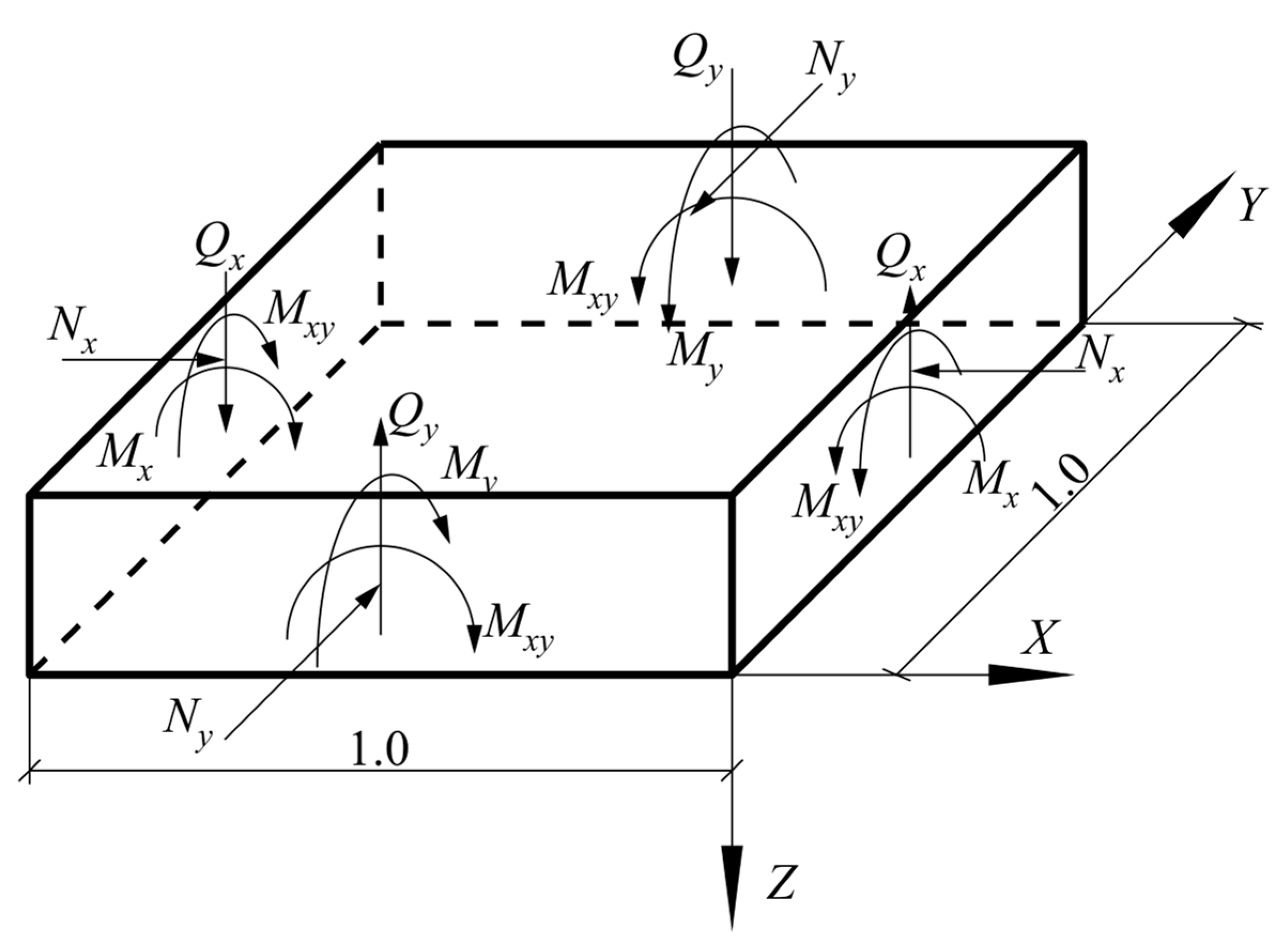
Thus, the analytical model of reinforced concrete floor slab in generalized form for the selected flat element is formed from the system of equilibrium equations of internal forces (Figure 1 and Figure 2):
M x , u l t M x · M y , u l t M y M x y 2 0 ; Q x Q x , u l t + Q y Q y , u l t 1 ; N x , u l t N x · N y , u l t N y N x y 2 0 .
At the same time, each of these equations of equilibrium forms a system of equations reduced to a plane stress state, where the stress distribution is determined by the condition of joint deformation:
a 22 4 F x 4 2 a 26 4 F x 3 y + 2 a 12 + a 66 4 F x 2 y 2 2 a 16 4 F x y 3 + a 11 4 F y 4 = 0 ;
where
  • F—stress function;
  • aik—stiffness properties of the slab under plane stress conditions.
For a single concrete volume and reinforcing elements, the system of equations is as follows:
-
for bending and torsional moments:
M x , u l t M x ; M y , u l t M y ;   M x y , u l t M x y ; M b , x y , u l t = 0.1 · R b · b 2 · h ; M s , x y , u l t = 0.5 · R s · A s x + A s y · h 0 .
-
for transverse forces:
Q u l t = Q b + Q s w ; Q b = 0.5 · R b t · b · h 0 ; Q s w = q s w · h 0 ;
-
for longitudinal forces:
N x , u l t N x ; N y , u l t N y ; N x y , u l t N x y ; N b , x y , u l t = 0.3 · R b · A b ; N s , x y , u l t = 0.5 · R s · A s x + A s y .
where
  • Мх—bending moment along the x-axis;
  • Му—bending moment along the y-axis;
  • Мху—torsional moment in the xy plane;
  • Мх,ult—ultimate bending moment along the x-axis;
  • Мy,ult—ultimate bending moment along the y-axis;
  • M b , x y , u l t —ultimate bending moment in concrete in the x- and y-axis;
  • M s , x y , u l t —ultimate bending moment of the reinforcement in the x- and y-axis;
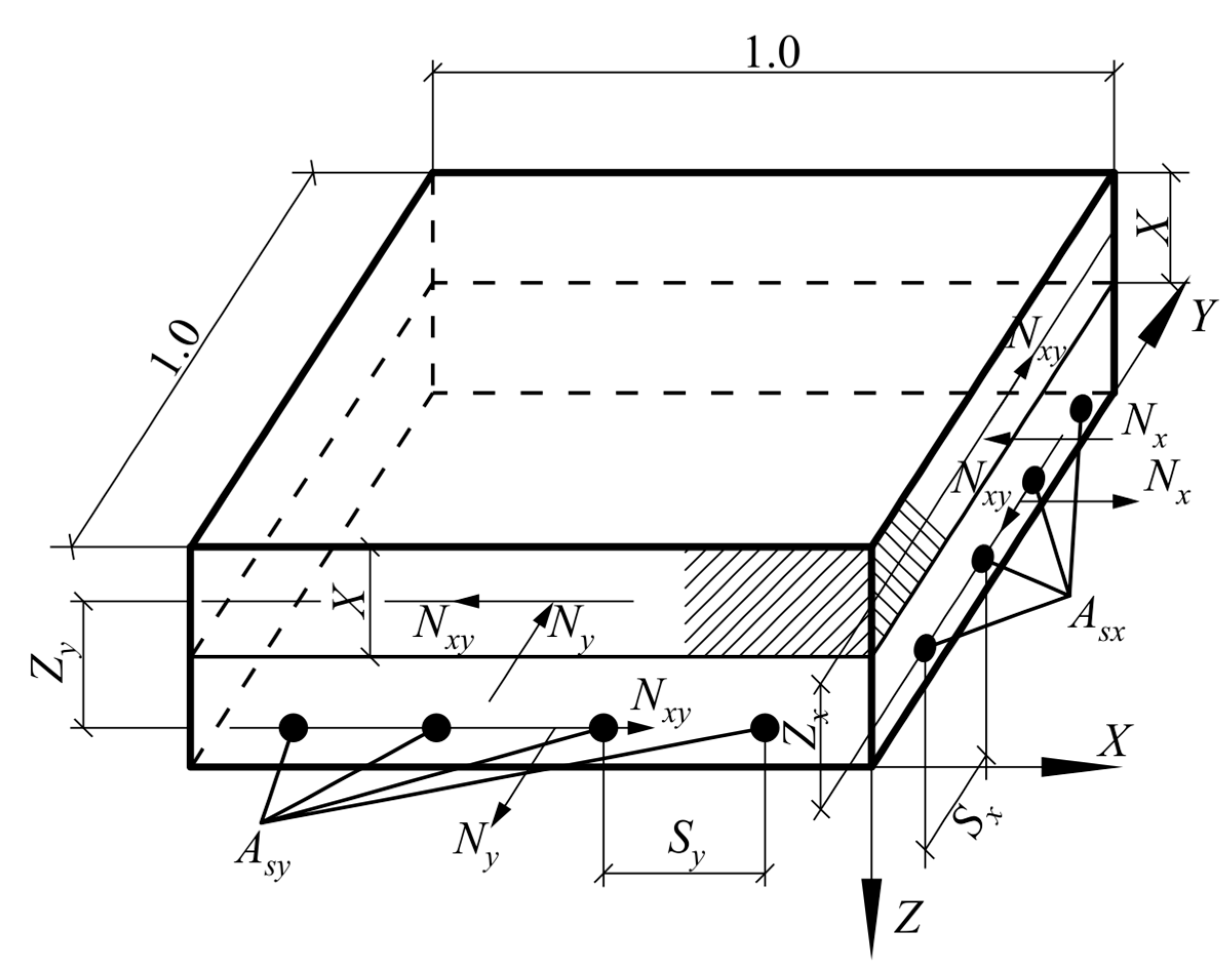
  • Nх—longitudinal forces along the x-axis;
  • Nу—longitudinal forces along the y-axis;
  • Nх,y—shear forces;
  • N x , u l t —ultimate longitudinal force along the x-axis;
  • N y , u l t —ultimate longitudinal force along the y-axis;
  • Qult, Qb, Qsw—transverse forces (ultimate, in concrete, in transverse reinforcement);
  • Rbt—tensile strength of concrete;
  • Rs—reinforcement tensile strength;
  • Аb—cross-sectional area of concrete;
  • Asx, Asy—reinforcement cross-sectional areas (x- and y-axis)
  • qsw—transverse reinforcement intensity;
  • b, h—width and height of the design cross-section of the support structure (pylon);
  • h0—effective height of the element section;
  • indexes (x, y)—belonging to calculation planes;
  • index b—single concrete element;
  • index s—single reinforcement element.
Thus, from the condition of equilibrium of internal forces on a single flat element (Figure 1 and Figure 2), an analytical model is formed that allows, with the necessary accuracy and in accordance with the boundary conditions, calculating reinforced concrete floor slabs in the punching zone under the action of a concentrated force and moments [1].
In [2,3], we derive the calculation of the load-bearing capacity of a reinforced concrete slab in the form of:
F p α · R b t · u c p · h 0 ,
where
  • α —coefficient, taking into account the (strength) class of the concrete element;
  • u c p —average value of the upper and lower perimeters of the punching pyramid.
For the punching shear calculation, the cross-section around the force transfer area of the concrete element is considered at a distance of h 0 / 2 normal to its longitudinal axis, with tangential forces acting on its surface (Figure 3).
The limit force taken by the concrete in the area of the punching zone is given by the formula:
F b , u l t = R b t · A b ,
where
  • R b t —tensile strength of concrete for the limit states of the second group;
  • A b —area of the design cross-section of the concrete at a distance of 0.5 h0 from the boundary of the application area of the concentrated force F with the working height of section h0, which is determined by the equation:
A b = u · h 0 ,
where
  • u —contour perimeter of the design cross-section;
  • h 0 —working section height of the reinforced concrete slab.
h 0 = 0.5   h 0 x + h 0 y ,
where h 0 x and h 0 y are the working height of the slab cross-section in the x and y directions, respectively.
The analytical model of a reinforced concrete slab in a punching mode has the following expression:
-
from the action of a concentrated load:
F F b , u l t F b , u l t = R b t · A b ; F F b , u l t + F s w , u l t F s w , u l t = 0.8 · q s w · u ;
-
from the combined action of a concentrated load and a bending moment:
F F b , u l t + M M b , u l t 1     M b , u l t = R b t · W b · h 0 .
Thus, the bearing capacity of a reinforced concrete beamless floor slab, according to the analytical model, depends only on the geometric characteristics of the contacting elements and the strength of the concrete and does not take into account the longitudinal reinforcement, which goes into reserve and can, of course, increase the load-bearing capacity.
In [2], three different shapes of pylons were investigated and tested on laboratory benches: square with 300 × 300 mm sides, angular with 300 mm length and 100 mm-width sides, and cruciform with 100 mm-width and 300 mm-length sides.
In [4], the results of experimental studies of the effect of the percentage of reinforcement and the thickness of the floor slab on the strength under punching pressure are presented. It is shown that an increase in the slab cross-section thickness and a decrease in the percentage of reinforcement lead to a reduction in the load-bearing capacity.
In [5], the cross-section thickness of the reinforced concrete slab is taken into account, and the percentage of reinforcement is not taken into account. It was found that for small percentages of reinforcement (µ < 0.5), the strength of the slab increases up to 35%, and for large percentages (µ > 1.5), it increases up to 50%.
In [6], it is proposed that the punching shear strength as a function of the limiting moment of resistance Mu should be determined as:
P p 4 h 0 · h 0 + a < 0.07 + 0.75 · M u h 0 2 · h 0 l s   ,
where
  • Рр—punching force (kN);
  • h0—working section height of the reinforced concrete slab (cm);
  • a—side dimension of a square column (cm);
  • Mu—ultimate bending moment;
  • ls—width of the bottom of the punching pyramid.
This approach was further developed in [7], where the dependence for slabs supported along the contour is proposed:
P p S · h 0 < 15 · 1 0.075 a h 0 5.25 φ 0 · f c
where
  • S—perimeter of the perforation contour of the calculated section;
  • φ 0 —numerical coefficient equal to the ratio of the breaking loads in pushing and in bending;
  • f c —cylindrical concrete strength.
It is also noted that the tensile strength of concrete under punching pressure is proportional to f c .
Summarizing the data from these studies, an expression is derived in [8]:
Р p 4 a + h 0 < 4 φ · f c
where φ —empirical coefficient.
The calculation model for the punching strength test according to [4], taking into account the designations in this paper, is shown in Figure 4. The punching resistance of a slab without transverse reinforcement has to be determined at the face of the column and at the test perimeter b 0 .
In this case, the faces of the punch pyramid are at an angle of 26.6°.
A critical evaluation of the traditional approach to the reinforcement of reinforced concrete slabs for punching was given in [9]. The experimental study was carried out on square reinforced concrete slabs of different thicknesses from 100 mm to 600 mm.
The results of this research concluded that there was a threefold decrease in the average breakaway stresses in a sloping crack during punching as the thickness of the reinforced concrete slab increased from 100 mm to 600 mm. With a slab thickness of 600 mm, the punching out occurred at a stress level of σ b r / R b r 0.6 .
It was also pointed out that the methodologies for the punching calculation of the pressure test were based on test results for slabs with a thickness of no more than 300 mm, which should be taken into account in the calculations by the introduction of a reduction factor for slabs with a thickness of more than 400 mm:
κ = 0.5 + 1 / 1 + 3 h 0 ,
where h0—working height of the plate (meters).
The analysis of the results of concrete slab punching tests carried out in the reviewed works indicates that as the thickness of the slab increases, the role of concrete in the nodal zone operation decreases. An understanding of these limitations is reflected in [1], where the fraction of transverse force taken up by transverse reinforcement during the punching process is limited to 50%.
In [10], the strength of beamless slabs is assessed under the U.S. design standard ACI 318, using an interaction equation that includes contributions from both shear and an unbalanced moment. Based on a reexamination of tests reported by Hanson and Hanson, the unbalanced moment at interior connections is shown to contribute far less to transverse shear than is assumed in the design. A simple limit analysis is presented that is more consistent with the observed behavior and accepted material limits and better predicts the test results.
In [11], the effectiveness of a new retrofitting technique to upgrade the structural behaviour of reinforced concrete (RC) deep beams without steel stirrups using carbon fibre reinforced polymer (CFRP) ropes as the only transverse shear reinforcement is experimentally investigated.
Promising results were derived, since the proposed strengthening technique enhanced the strength and altered the brittle shear failure to a ductile flexural one.
In [12], the effectiveness of slightly reinforced thin U-shaped cementations mortar jacketing for the repair of damaged shear-critical reinforced concrete beams is experimentally investigated.
Based on the overall performance of the beams, it is deduced that the shear strength and deformation capability of the jacketed beams were substantially increased compared to the corresponding capacities of the initial beams.
Comparisons indicated that jacketed beams can alter the failure mode from brittle shear to ductile flexural under certain circumstances.
In [13], the shear strength calculation equation was developed on the basis of improved statistical analysis of the database, supplemented by finite element analysis.
The work [14] presents the results of experimental studies, consisting of 13 symmetrical punching tests of beamless floor slabs. The study focuses on the effect of different supported area sizes and slab flexibility. Other investigated parameters are the coefficient of reinforcement for bending and for shear.
The article [15] presents the results of experiments on 16 samples of flat slabs, with and without transverse reinforcement. The tests were aimed at studying the effect of a set of mechanical and geometric parameters on the shear strength and deformation of flat plates supported by internal columns.
The results of studies of strength and deformability on fragments of the connection of columns and monolithic floor slabs of a beamless frame during crushing are given in [16]. The variable parameter was the shape of the cross section of the column. It was established that with an increase in the ratio of the sides of the section of the column, the calculated strength values exceed the experimental ones. This indicates that the normative method of calculation does not take into account the real nature of the distribution of forces in the punching zone of the plate.
In [17], nine loaded, reinforced concrete slabs resting on centrally located rectangular columns were tested. The lengths of the adjacent sides of the column had ratios in the range of 1–4.3. The shear forces were consistent with those calculated according to building codes for samples with a column aspect ratio of less than 2.0. For large ratios, the shear forces were less.
In [18], the results of punching tests of three full-scale samples of reinforced concrete slabs are presented. The main attention is paid to the punching failure modes obtained using different distributions of transverse reinforcement and their corresponding failure loads. Three failure modes were observed—punching without shear reinforcement, stamping outside the shear zone, and stamping in the shear zone due to concrete failure.
In [19], based on the punching shear provisions according to Eurocode2, a new Uniform Design Method (UDM) for flat plate and column bases is developed.
Buildings made of reinforced concrete are usually reinforced with vertical diaphragm walls located around the stair-lift nodes. In [20], the effect of elongation of a support on the resistance to punching of the internal connections of a column–slab without transverse reinforcement is studied. Therefore, punching in the corners of the walls can be missed in the design.
It is often difficult to distinguish between bending and bursting failure modes in tests to study the effectiveness of shear reinforcement in providing strength and ductility to slabs. Indicative results can only be obtained when the flexural reinforcement ratio is high enough to exclude the possibility of failure in the flexure prior to bursting. In [21], the influence of the reinforcement coefficient on bending is studied on the failure mode, strength, and ductility, using experiments on internal slab–column joints transmitting shear force or shear force in combination with an unbalanced moment. The test results show that it is sufficient that the breaking load in bending exceeds the bursting breaking load by 1.7 times.
The paper [22] focuses on the shear strength of pierced slabs supported by rectangular columns.
Twenty slab specimens were tested under concentrated loads, and it was found that the stresses in the slabs were concentrated mainly around the shorter sides of the rectangular columns. Holes greatly reduce the force of impact, and if the use of a hole is unavoidable, the best place for it is lengthwise on the long side of the column.

1.3. Analysis of Experimental Results

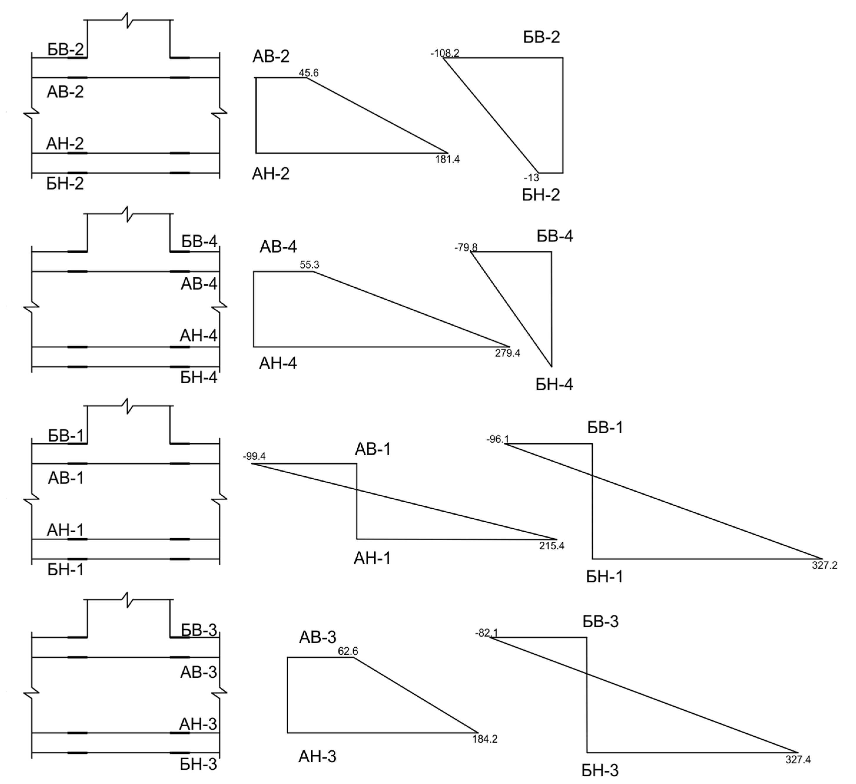
1.3.1. Deformations of Concrete and Reinforcement

With the participation of the author, experimental studies on punching by a static load were carried out.
Based on the values of relative deformations of concrete and reinforcement obtained in the course of the experiment for each specimen, diagrams of the distribution of deformations over the cross-section for static loading were constructed. The diagrams for static loading are plotted in accordance with the data obtained by taking into account the stage of loading.
In accordance with the placement of the sensors (see Figure 5), we will give an example of the constructed diagrams (see Figure 6 for one sample). Figure 6 shows diagrams corresponding to strain during the static loading stage, and Figure 7 shows diagrams corresponding to the failure stage of loading.
Here, C20 is the concrete class, and h100 is the slab thickness in mm.
Here, the designations have the following values:
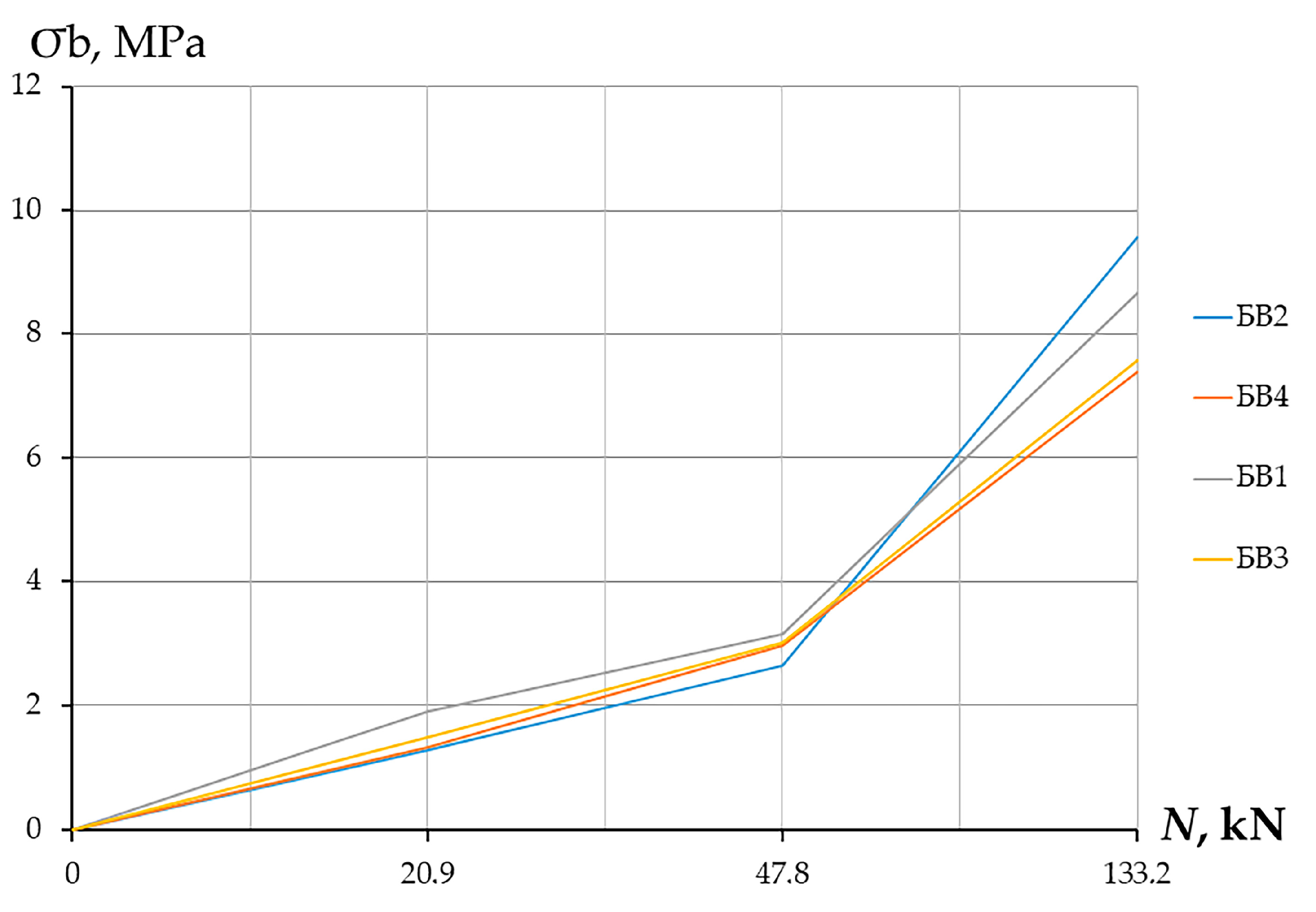
  • БВ—deformations of the concrete of the top zone,
  • БН—deformation of the concrete of the bottom zone,
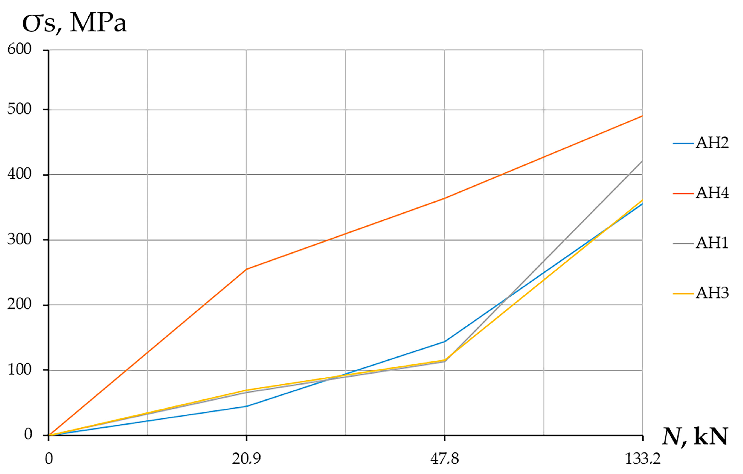
  • AB—deformation of the reinforcement of the top zone,
  • AH—deformation of the reinforcement of the bottom zone.
It is evident from the presented graphs, based on the analytical processing results for the specimens of identical construction, but differing in loading, that during static loading, the increase of stresses in the concrete and reinforcement, as well as the increase of the internal moment of the section, occurs in proportion to the external loading. Three stages of the stress–strain state of the specimen can be distinguished in the static loading.
The first stage, corresponding to 30–40% of the destructive load, is the elastic stage of the specimen structure. There is a gradual increase in the stresses in the tensile reinforcement up to 20% of the maximum, and the stresses in the compressed concrete increase up to 25%. The end of this elastic phase ends with the appearance of normal cracks on the bottom face of the specimen surface and the beginning of active development of the reduced surface of the ramming in the top compressed zone of the concrete.
In the second stage, there is an elastoplastic stage of work of the specimen structure. Normal cracks develop in the lower zone of the concrete, and stresses actively increase in the compressed zone of the concrete, forming the reduced surface of the ramming. The end of this stage is characterised by the active development of oblique cracks at 80–90% of the failure load.
From the analysis of the obtained diagrams, it can be concluded that during sequential static loading, there is a gradual increase in the deformations of the reinforcement of the bottom zone AH-1, AH-2, AH-3, and AH-4 and the deformations of the concrete of the bottom zone БН-1, БН-2, БН-3, БН-4. Gradually, with an increasing load on the test specimen, there is an increase in the deformation of the reinforcement in the top zone AВ-1, AВ-2, AВ-3, and AВ-4 and the deformations in the concrete in the top zone БВ-1, БВ-2, БВ-3, and БВ-4. Formation of the concrete of the compressed zone takes place, which increases up to the moment of fracture. Concrete strain diagrams are sign-variable, indicating compressive and tensile strain on different sides of the specimen.
The analysis of the deformations of the concrete and the reinforcement recorded during the investigations shows the following results.
Under the action of a static load, the deformations of the concrete and the reinforcement reached the following values:
-
The mean values of the maximum deformations for the compressed concrete were 163 × 10−5;
-
The mean values of the maximum deformations for the stretched concrete were 61 × 10−5. It should be noted here that the sensors continued to operate after the first cracks formed;
-
The average values of the maximum deformations for the compressed reinforcement were 30 × 10−5;
-
The average maximum deformation values for the tensile reinforcement were 248 × 10−5.

1.3.2. Stresses on Concrete and Reinforcement

For each test specimen, using the relative strain values obtained, the numerical values of the stresses in the reinforcement and concrete were determined, as well as the forces occurring in the tensile (lower reinforcement). These analytical operations were carried out using the following formulas:
σ s t = ε s t · E s  
N s t = σ s · A s  
σ b c = R b · ε ε R K · 1 ε ε R 2 + ε ε R 3 2 ε ε R
The height of the concrete compression zone was also determined for each specimen:
A b · σ b + σ s · A s c = σ s · A s
b · x 2 · σ b + σ s · A s c = σ s · A s
x = 2 · σ s · A s σ b · b
The results obtained for the samples tested under static loading are shown in Table 1.
The following dependence graphs are plotted for each sample (shown by the example of sample S h 100 C 20 ) (see Figure 8, Figure 9 and Figure 10).
Based on the obtained stresses, the magnitudes of the bending moments in the sections along the faces of the column were determined. In this case, the area of the reinforcement limited by the lower base of the edge of the punching pyramid was taken into account. The area of concrete is determined by the upper part of the face of the same pyramid.
From the presented graphs, made according to the results of the analytical processing of the results for the specimens of the same design, but differing in different loads, it can be seen that under static loading, the increase in stresses in the concrete and the reinforcement, as well as the increase in the internal moment of the section, occurs in proportion to the external loading. In this case, under static loading, several stages of the stress–strain state of the sample can be distinguished.
At the first stage, which corresponds to 30–40% of the breaking load, the elastic stage of the work of the sample structure occurs. There is a gradual increase in stresses in the tensile reinforcement up to 20% of the maximum, and stresses in the compressed concrete increase up to 25%. The end of this elastic stage of work ends with the appearance of cracks on the lower surface of the slab and the beginning of the formation of a reduced punching surface in the compressed zone of concrete.
At the second stage, the elastoplastic work of the sample structure takes place. There is a development of cracks in the concrete in the tensile zone of the slab, as well as an increase in stresses in the compressed zone of the concrete. The end of this stage is characterized by the active development of inclined cracks at the punching boundary of 80–90% of the breaking load.
The results of the experimental studies of the resistance to punching of the junction of the overlap with the column under static loading and of the analysis of the development of the stress–strain state of the samples until the moment of destruction showed the following:
-
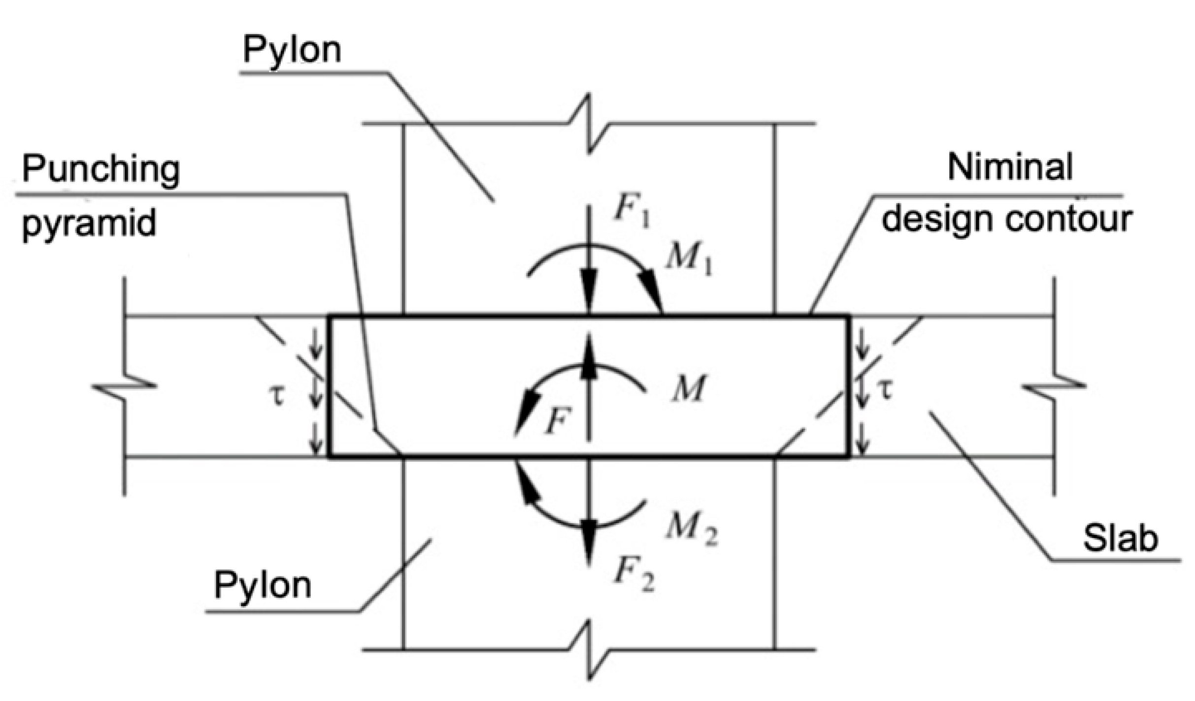
in the presence of longitudinal reinforcement, the destruction of the sample during the formation of cracks in the tensile zone does not occur, but a pair of forces is formed that forms a compressed zone of concrete within the apex of the punching pyramid and a tensile one from the lower reinforcement;
-
resistance to vertical load is exerted by the compressed zone of concrete formed by the surface of the reduced punching pyramid.
Furthermore, an analysis of the results of [1,2,3] shows that:
-
the summation on the edges of the punching pyramid of the tensile concrete and transverse reinforcement bearing capacity does not correspond to the actual fracture pattern;
-
the assumption of a uniform distribution of shear stresses in concrete over the entire area of the design cross-section is inconsistent with the experimental data;
-
the normative calculation method for concretes of classes C40 and C45 in some cases shows a significant increase in the load-bearing capacity of the concrete punching compared to the experimental;
-
the analysis does not take into account the longitudinal reinforcement of the reinforced concrete slab, the asymmetric stress state at the different faces of the columns, or the loading mode;
-
the bending moments acting in the columns cannot affect the floor slabs’ stress–strain state outside the limits of their cross-sections.
The results of the analysis [3], as well as the experimental data obtained by the author, led to the following observations:
-
tangential stresses are only uniformly distributed within the working height of the cross-section, not along the height of the concrete compression zone;
-
the bearing capacity of the slab obtained by analytical calculations in some cases exceeds those obtained from experiments;
-
there is unreasonable consideration of column forces from bending moments in the punching calculation of slabs;
-
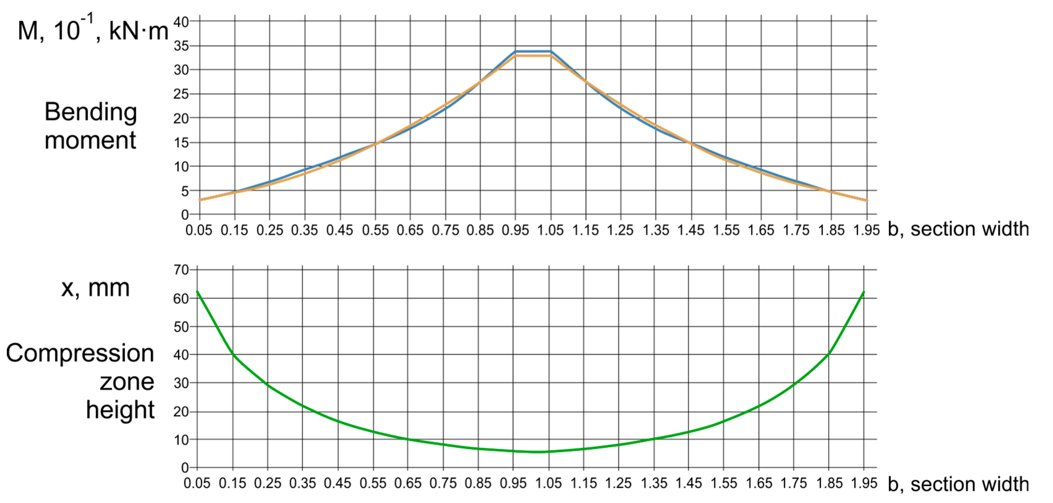
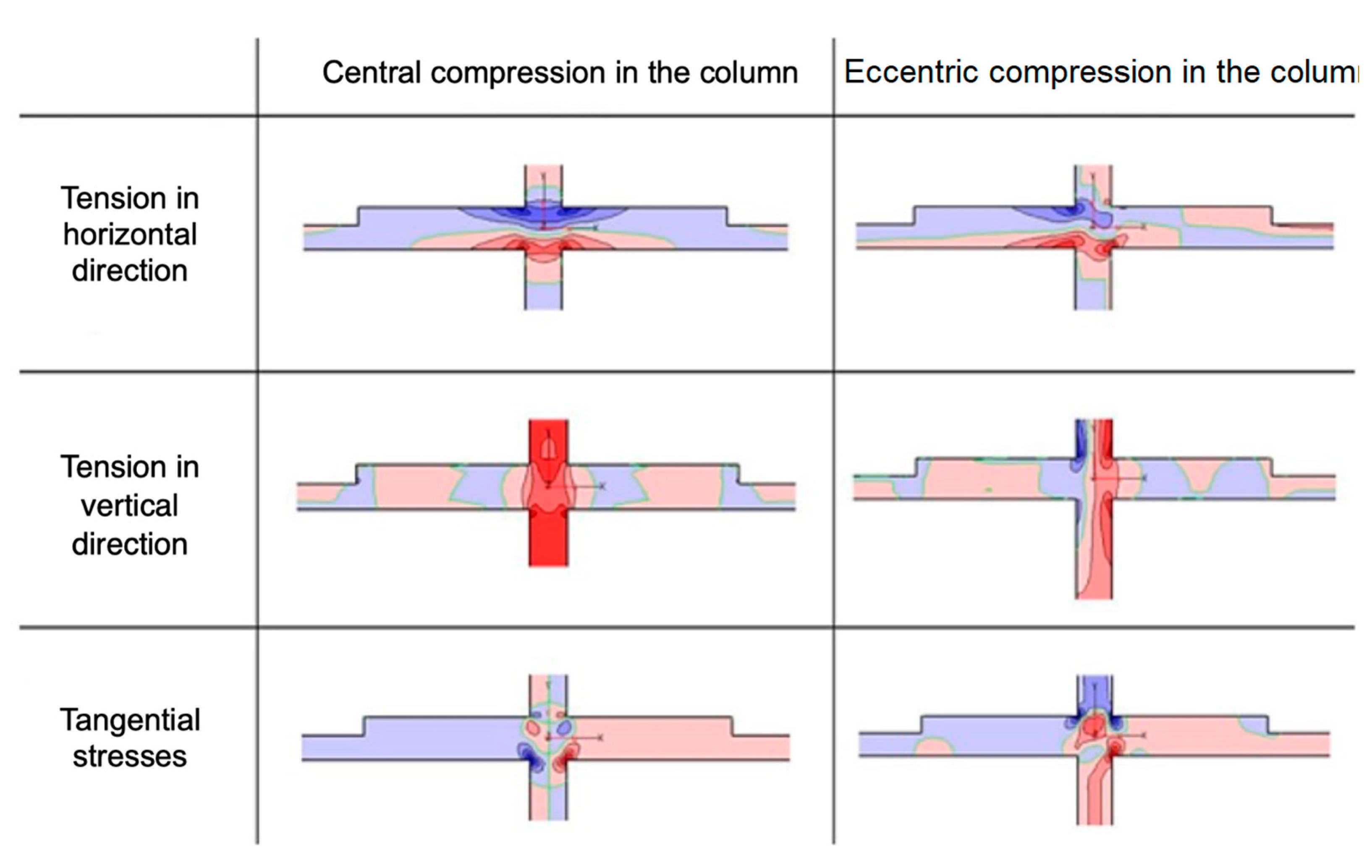
the failure mechanism of the punching failure depends more on the distribution of internal forces (moments), the height of the concrete compression zone, and the reaching of the yield point of the longitudinal tensile reinforcement (see Figure 11).
In [2], experimental data were obtained on the effect of the pylons’ cross-sectional shape on the character of the cracking of the floor slab during punching. Three shapes were investigated and tested on laboratory benches (Figure 12).

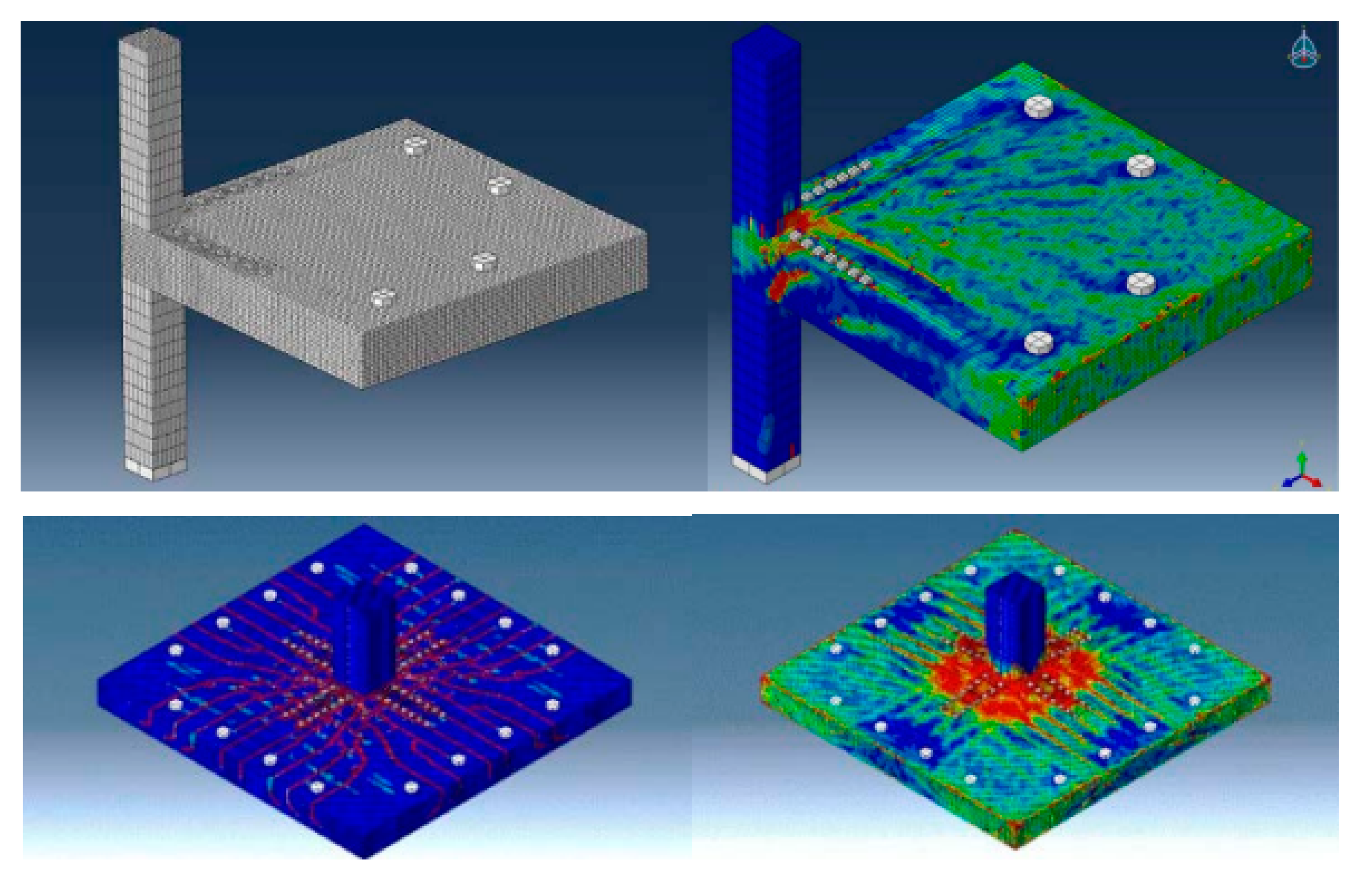
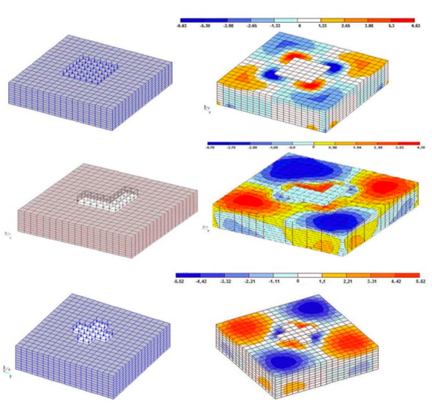
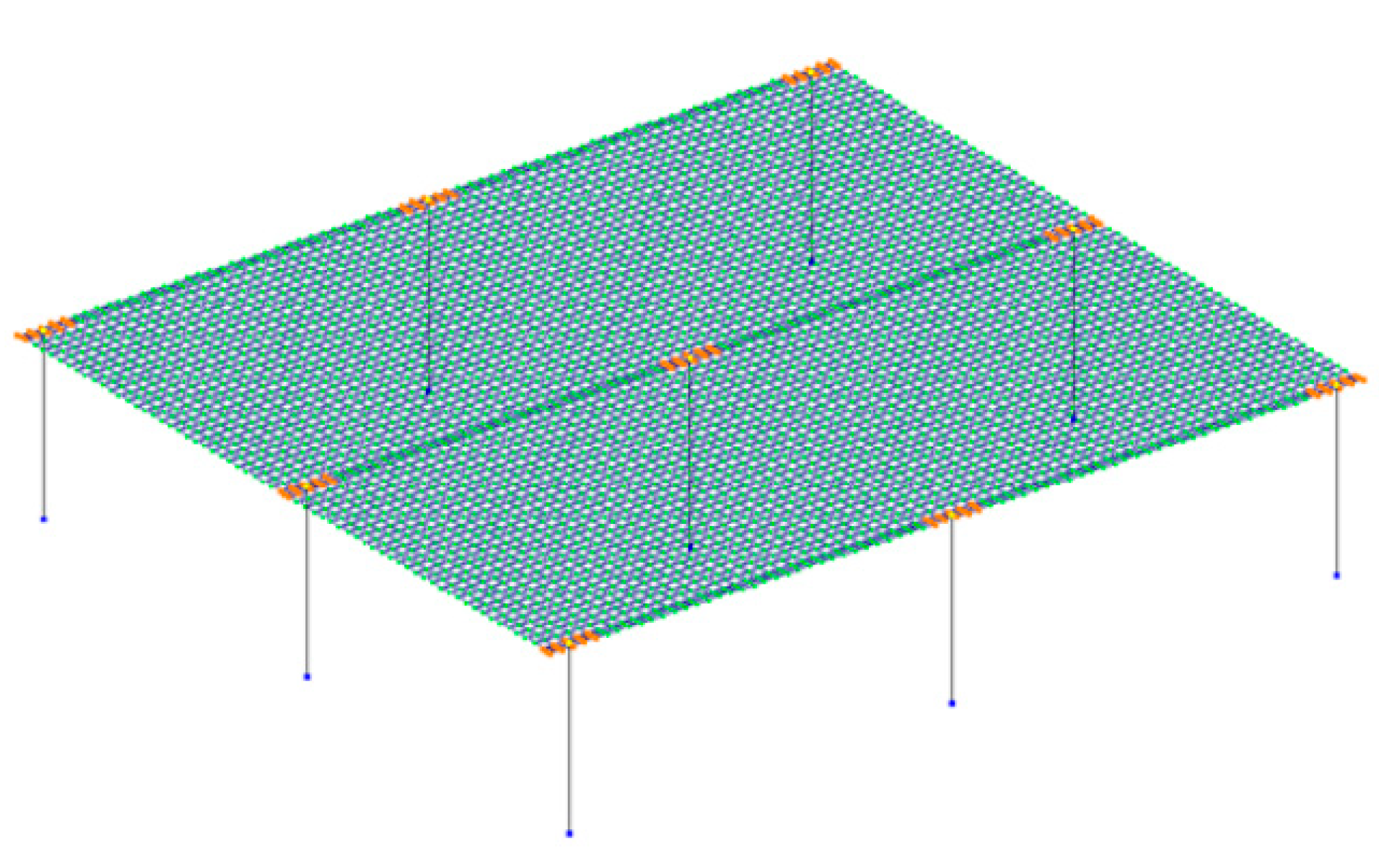
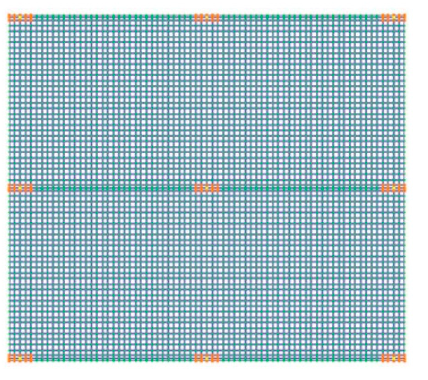
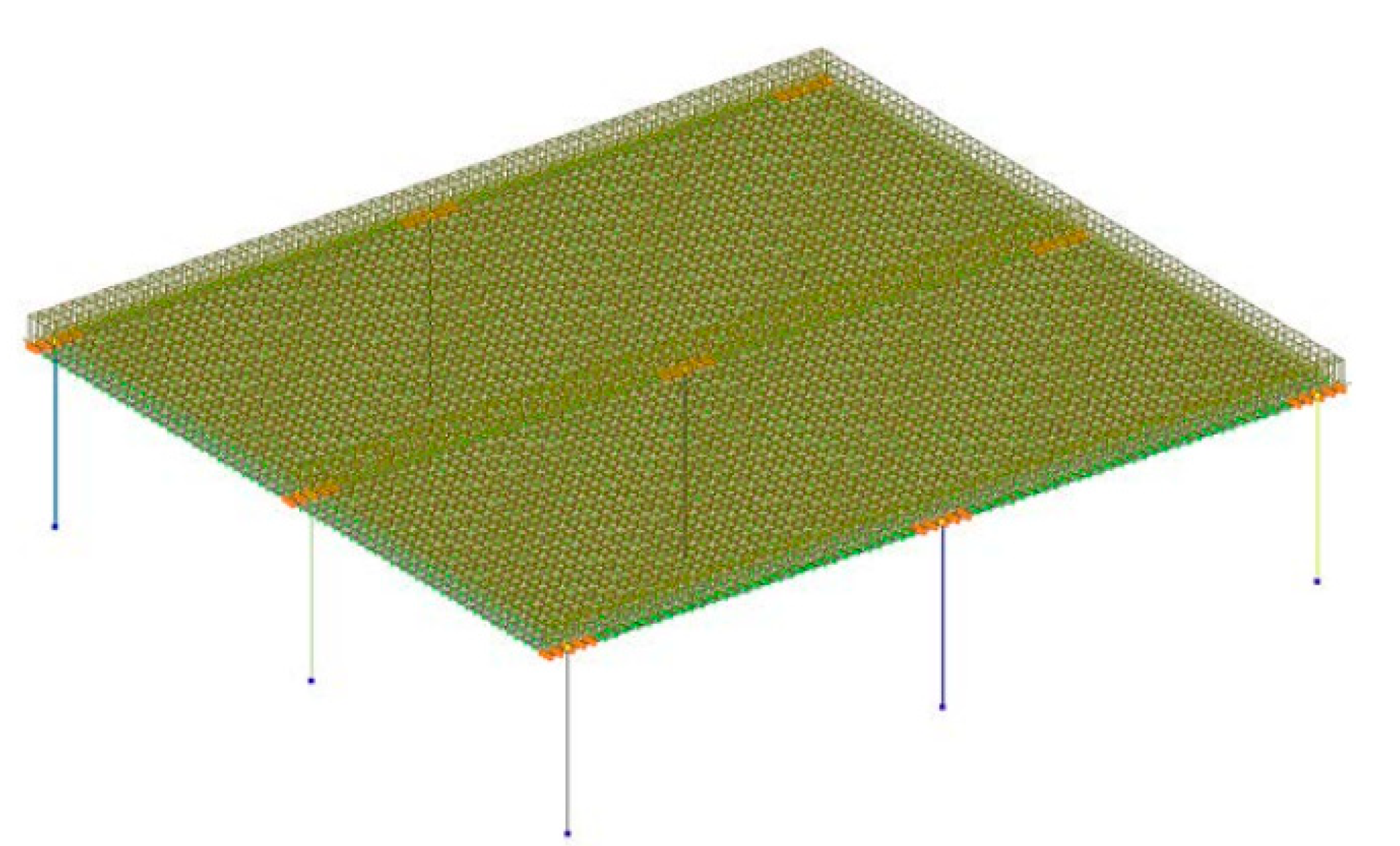
2. Materials and Methods

Finite Element Modeling of Flat Reinforced Concrete Floor Slabs

The modelling of a flat reinforced concrete floor slab was carried out in special software packages (Figure 13), as well as in [2] (Figure 14) and in [23] (Figure 15).
A flat model (Lyra) was used to estimate the distribution of shear forces causing punching. The reinforcement in a discrete form was not used in this model. In all models, the principle of detailed discretization was used, when the considered fragment of the model belongs to the building, and the support fastenings and boundary conditions reproduced this state. The concrete was modelled by shell finite elements of the plate type.
To clarify the nature of the stress distribution on a flat section of the junction of a plate and a column, flat shell elements were used, with the possibility of visualizing the main stresses vertically, horizontally, and diagonally (Figure 15).
The calculations were performed in a physically non-linear formulation for the action of a static load. The non-linearity of the concrete behaviour was taken into account, based on the Newton–Raphson method, in combination with the chord method. The breakdown condition was considered to be the interruption of the count, as evidence of the poor conditionality of the stiffness matrix. The static load was set to increase monotonically, with an increment of 10 kN at each step. In addition, the level of cohesive deformations was controlled, which was approximately described by the ultimate tensile deformations of the concrete and amounted to 0.00015.

3. Results

3.1. Calculation Results for the Pylon Punching Shear of the Monolithic Slab

In the LIRA CAD software, it is possible to automatically construct an indentation contour and obtain the corresponding value of the indentation force, displacement, moments, and other information in the form of iso-fields and numerical representations.
In order to construct a finite element model, according to [24], for a given software numerical simulation in a 2D research vector, it is necessary to specify the correlation dependence between the parameter of the ratio of the overall dimensions of the pushing structural element (column/pylon) and the bearing capacity of the flat reinforced concrete slab.
The following design data are taken into account:
-
the pylon sides’ ratio is taken as 1/4;
-
the minimum size of the support pylon is 200 mm;
-
the cross-sectional dimensions of the pylons are assumed to be 200 × 800, 200 × 1000, 200 × 1200, 200 × 1400, and 200 × 1600 mm;
-
the pylon spacing is assumed to be 6000 mm;
-
in order to avoid eccentricities and to simplify the investigations, a uniformly distributed load is applied to the slab, and the calculation model is assumed to be symmetrical.
To avoid specifying the pylons as 3D finite elements and to avoid exporting the calculation results, the pylons are modelled with rod finite elements in the form of absolutely rigid bodies that pass through the pylon axes. With their help and by combining the displacements of some plate nodes, the pylons’ support contours are set.
The general view of the FE model is shown in Figure 16, in which the punching contours (Figure 17) and loads (Figure 18) are specified.
The finite element model revealed the presence of force concentrators at the pylon’s corners (see Figure 19 and Figure 20), which is confirmed by the results of experimental studies [4,22,25,26,27]. It is also observed that the concentration intensity of forces at the corners of the pylon is directly related to the geometric parameters of the support element (in particular, the aspect ratio of the pylon). As the size increases at one of the pylon’s sides, the concentration of forces increases at the corners; however, closer to the centre of the long side, the punching force decreases.
The calculation contour of the monolithic slab penetration by the pylon is shown in Figure 21.
The contour is divided into three sections (1,2, and 3). The average forces along the length of the sections are determined by the Lira CAD 2021 R2 Update 3.1 software. The values of the averaged bending moment diagrams on the long opposite segments 1 and 3 are equal and do not affect the load-bearing capacity (pylon width а = 200 mm; side length = 800 mm, 1000 mm, 1200 mm, 1400 mm, and 1600 mm). The thickness of the floor slab is h = 200, 400, 600, 800, and 1000 mm. The protective layer of the upper reinforcement mesh is 30 mm. The concrete classes are C25 ( R b t = 1.05   MPa ) and C40 ( R b t = 1.4   MPa ).
To determine the maximum possible emerging stresses, it is necessary to load the plate with an ultimate force, according to Formula (6). When a pylon is loaded with such a force, a stress concentration occurs in its immediate vicinity. Therefore, it is necessary to bring the loading of the pylon’s loading area into compliance with the loading of the above pylon punching zone.
The slab thickness is 200 mm, class C25 concrete, with dimensions of 800 by 200 mm pylons.
The average effective height of the slab is h 0 = 200 30 = 170 mm.
The calculated load on the load area of the pylon is:
q = R b t u h 0 / A = 1.05 0.17 2.68 10 3 / 42.16 = 11.35   kN / m 2
The calculated punching pattern is created at the distance of 0.5 h0 from the pylon edges and consists of three parts with the length:
L 0 = a + h 0 = 200 + 170 = 370   mm  
The strength condition is F u + M у W b , y R b t h 0 .
The calculation forces are as follows:
F = L Q y 1 + Q x 2 + Q y 3 = 0.37 113.84 + 263.16 + 113.84 = 181.61   kN
where Qy1, Qx2, and Qy3 are averaged stress values at Section 1, Section 2 and Section 3, calculated by Lira-CAD (see Figure 22 and Figure 23).
M y = L M y 1 M y 3 / 2 = 0.37 64.87 64.87 / 2 = 0   kNm .
The perimeter of the design contour is as follows:
u = 3 L 0 = 3 370 = 1110   mm
F u + M y W b , y = 163.61
R b t h 0 = 1.05 170 = 178.5   N / mm .
163.61 < 178.5 .
The strength condition is met, the load capacity of the plate is secured, and the load capacity safety factor is 178.5 / 163.61 = 1.091 .
Further calculations are automated by means of the MS Excel program.

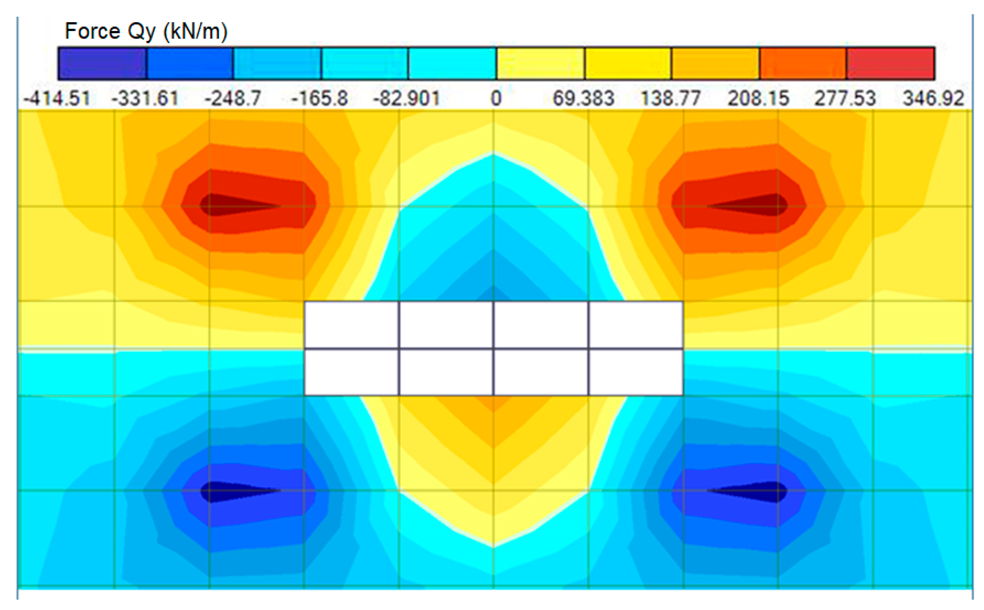
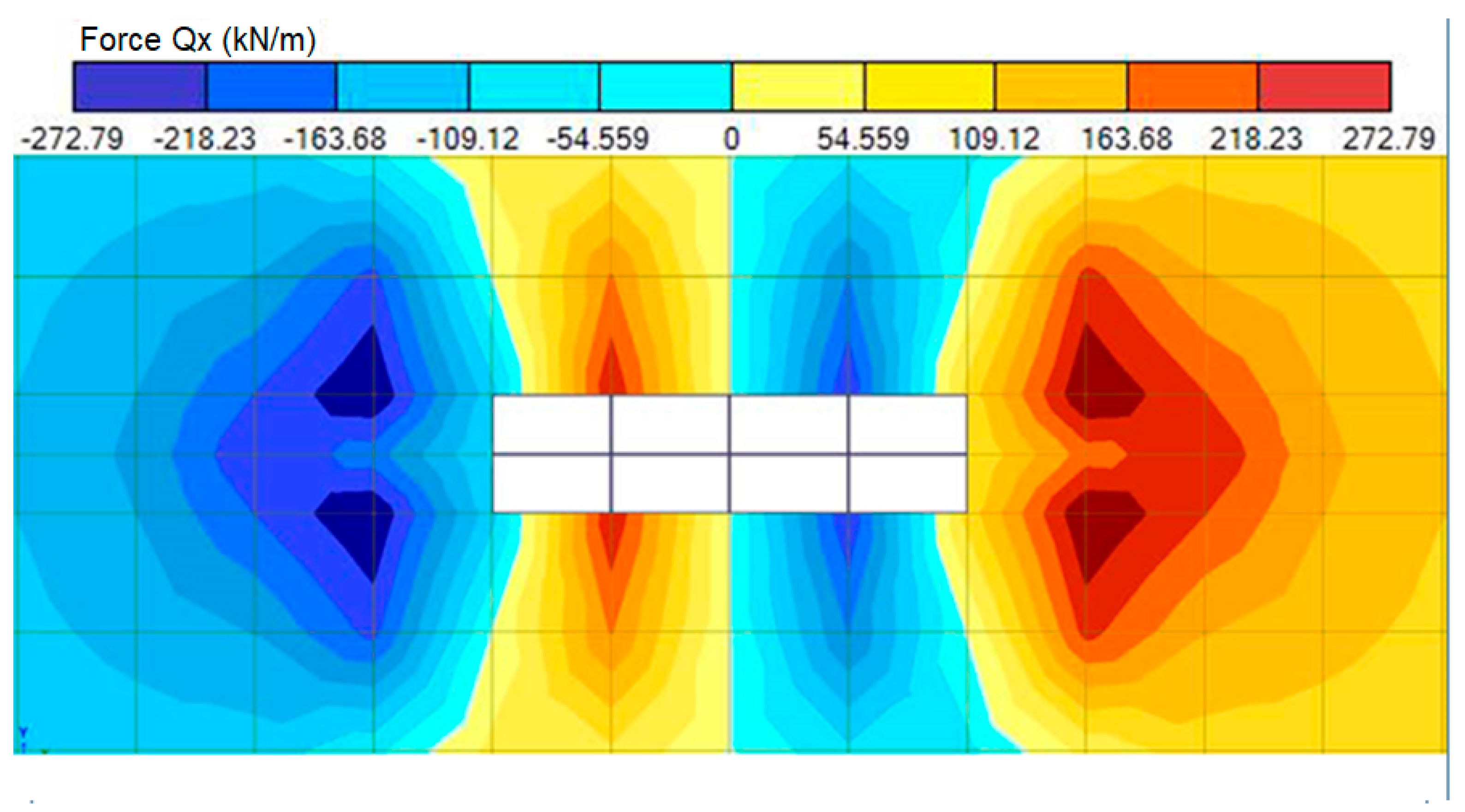
3.2. Influence of the Design Parameters of the Contacting Elements in Beamless Floor Slabs on the Calculation of the Punching Pressure

The load-bearing capacity safety factor values calculated in MS Excel are shown in Table 2.
The data obtained are shown as a graph of the load-bearing capacity coefficients for a slab of concrete of class C25 on its thickness (Figure 24) and the length of the pylon side (Figure 25).
The load-bearing capacity safety factor indicates the intensity of the load concentration in the punching zone. The bearing capacity safety factor can be plotted as a linear function of the pylon side lengths. Therefore, it becomes obvious that the greater the aspect ratio in a rectangular pylon, the greater the load concentration on the short side. It can also be observed that the stress concentration only increases for a slab thickness up to 400 mm, and then it decreases, i.e., the higher the working height of the slab, the lower the stress concentration along the base of the punching pyramid.

4. Discussion

The presented article reveals the load-carrying capacity of beamless floor slabs under punching from such parameters of contacting elements as slab thickness, geometric parameters of pylon sides, and concrete class. It is also found that:
-
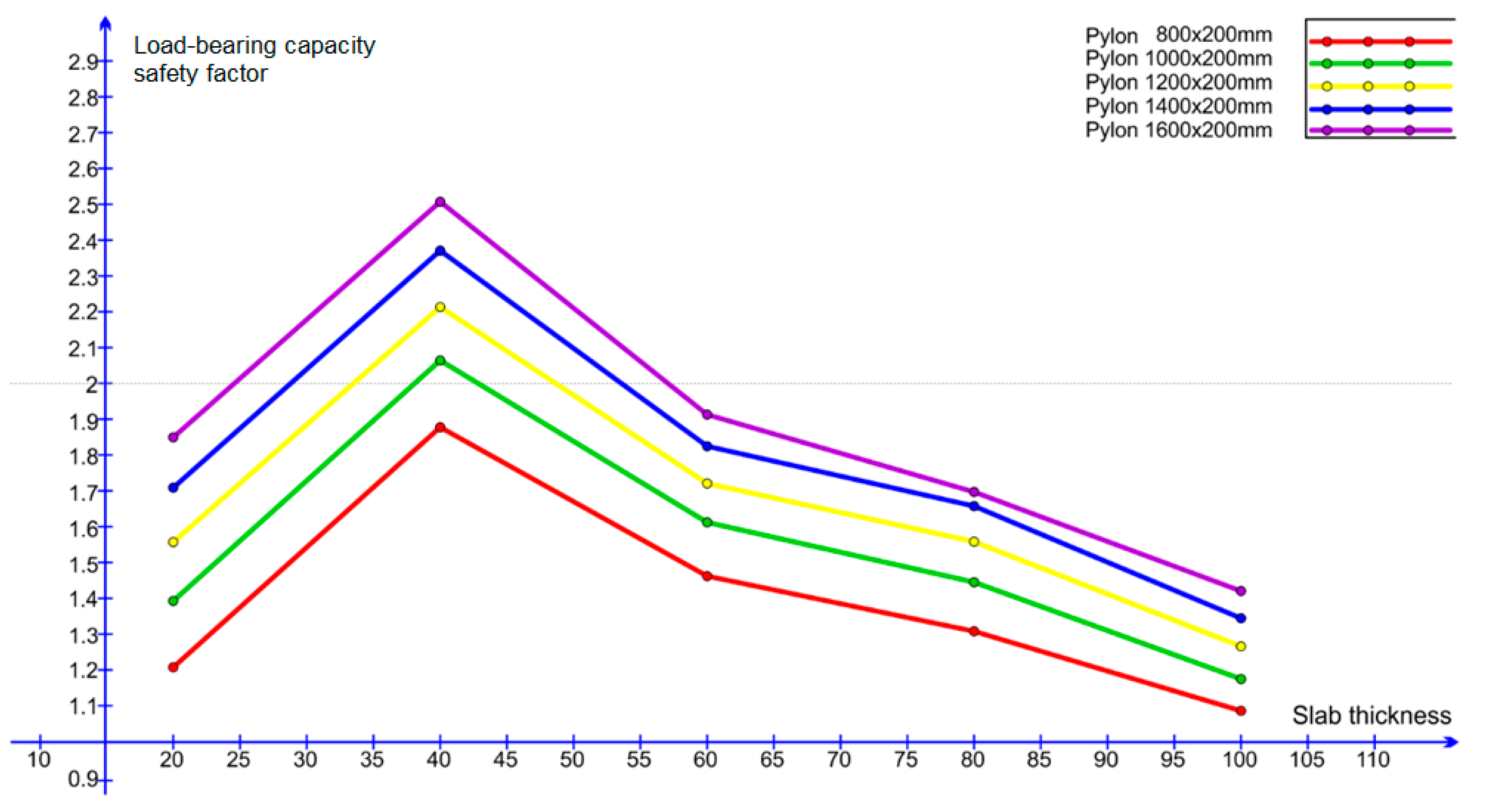
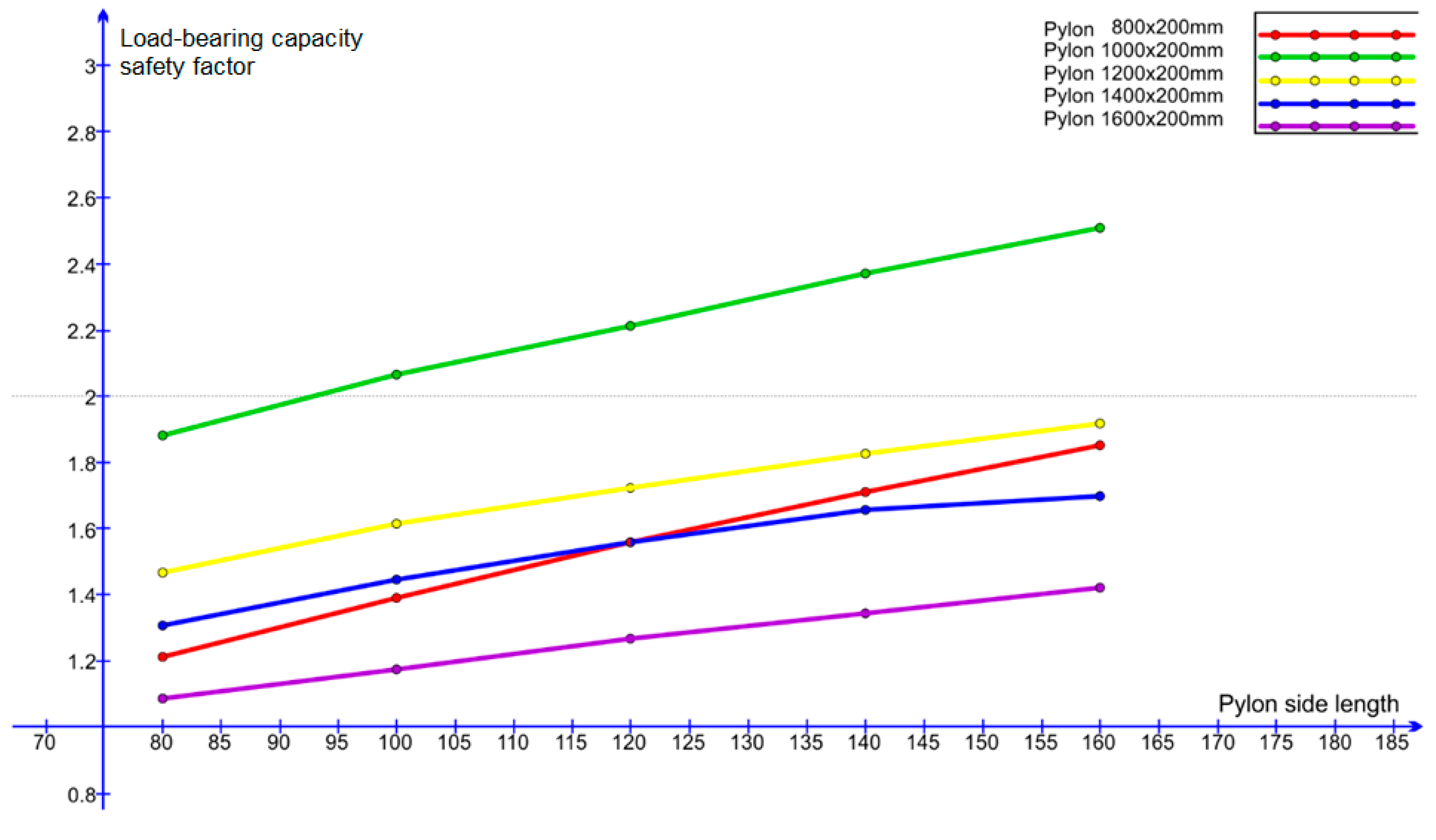
As the length and the ratio of the sides of the pylon cross-section increase, the concentration of forces increases proportionally, which lowers the load-carrying capacity of the floor slab. For the concrete classes C25 and C40 and the slab thickness of 200 mm, the increase of the pylon side length from 800 mm to 1000 mm leads to the increase of the bearing capacity safety factor by 14–15%, and the increase of the pylon side length from 1400 mm to 1600 mm leads to the increase of the bearing capacity safety factor by 7–8%. For reinforced concrete floor slabs with a thickness of 1000 mm, the safety factors are 8% and 4%.
-
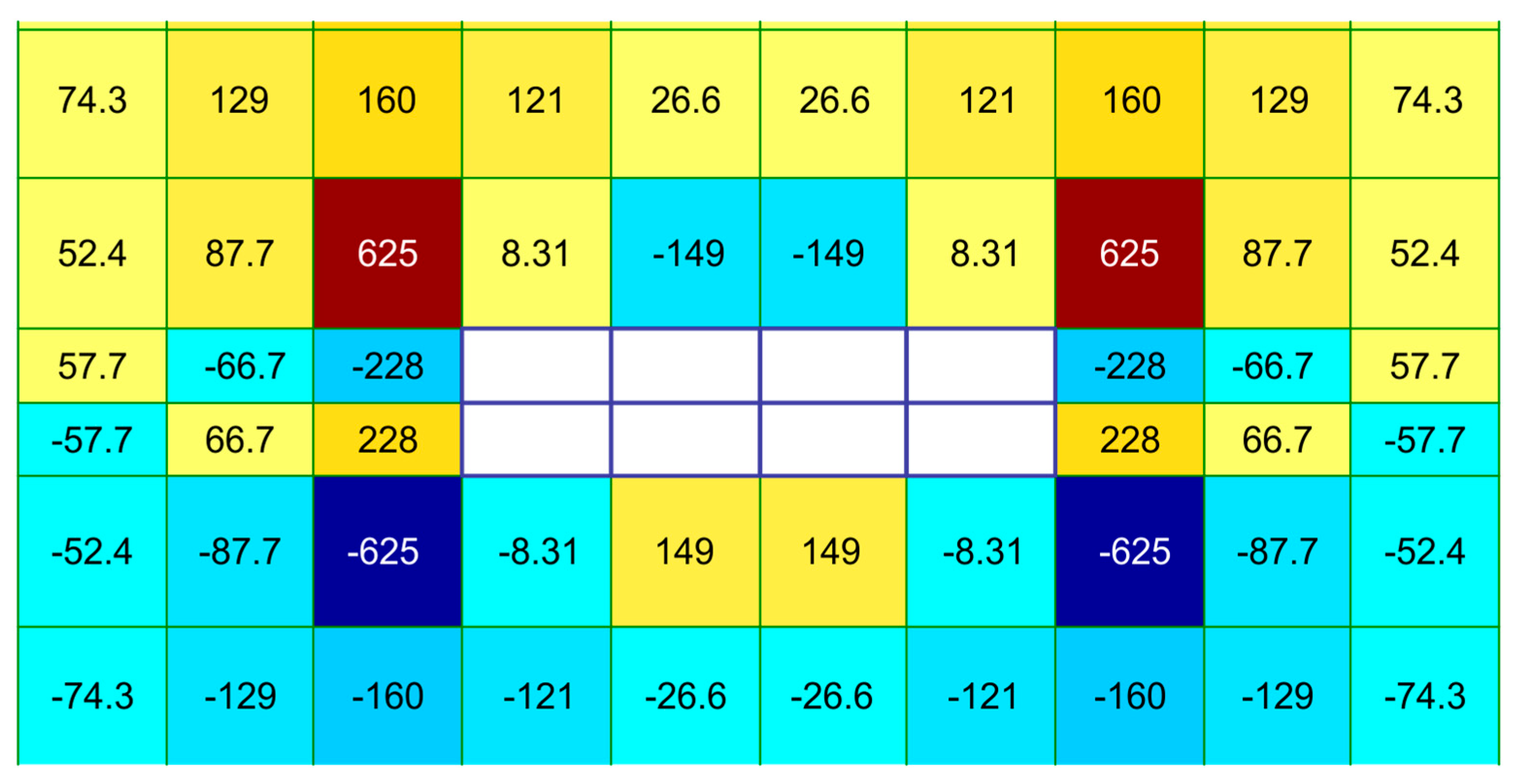
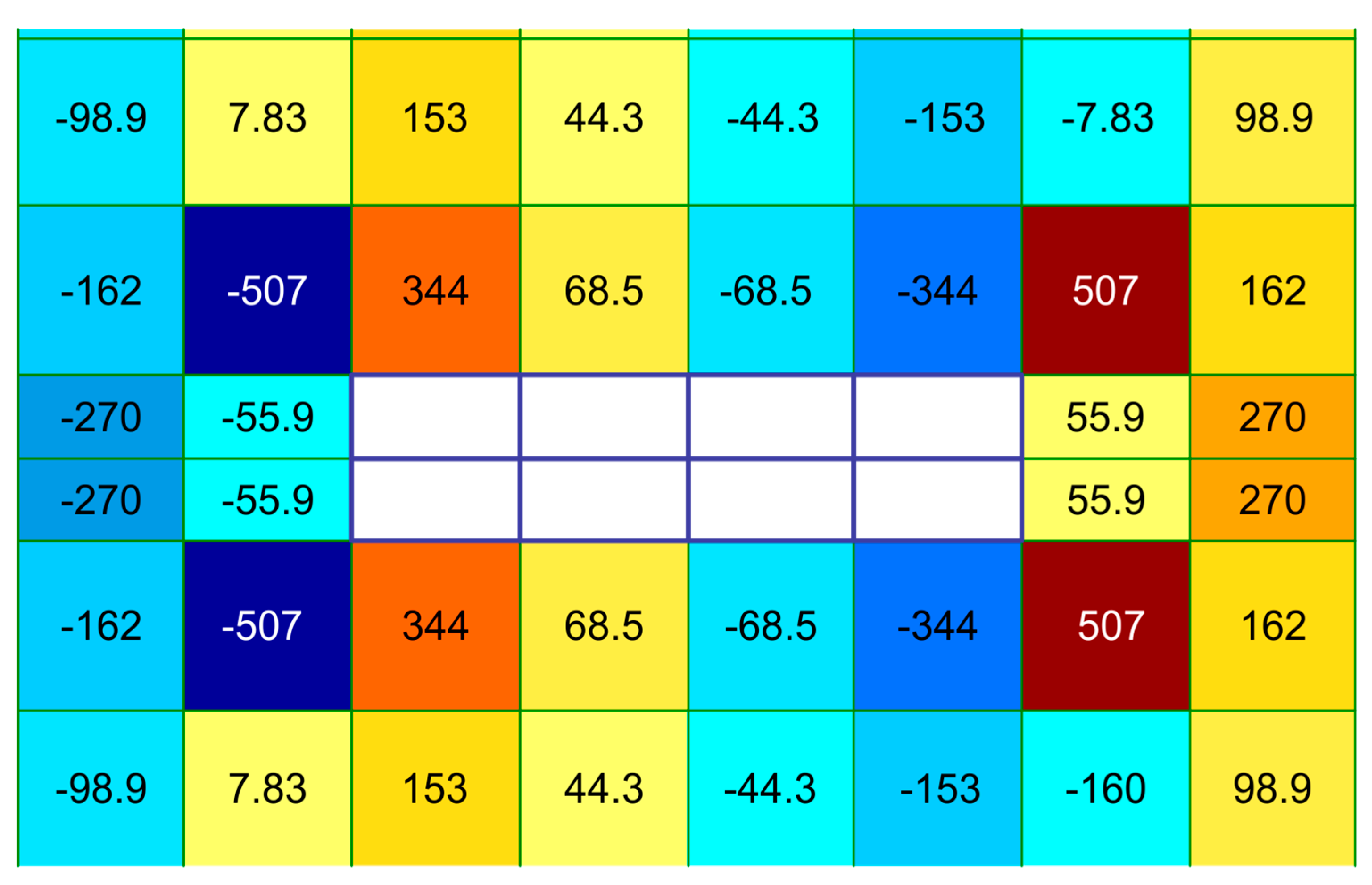
The force concentration graph in the design cross-section of a 400 mm-thick slab has a maximum value, irrespective of the concrete class and the cross-sectional dimensions of the pylon. As the slab thickness increases, there is a sharp decrease in the concentration of forces in the design cross-section, followed by a damping. There is also a tendency of convergence of the graphs for different pylons with increasing slab thickness. Thus, for concrete of class C25, the difference in concentration values for pylons with sides of 800 mm and a slab thickness of 200 mm is 53%, and for 1600 mm, it is 30%. For concrete C40, these values were 53% and 31%.
-
The concrete class has a significant influence on the load-bearing capacity of the floor slab, but it has little influence (up to 10%) on the load-bearing capacity safety factor.
-
In the presence of longitudinal reinforcement, there is no fracture of the specimen when cracks form in the tensile zone, but a pair of forces forms from the compressed zone of the concrete within the apex of the punching pyramid and the tensile zone from the lower reinforcement.
-
The load is resisted by the compressed zone of the punching pyramid.

5. Conclusions

Based on the analysis of the results, it can be stated that the character of the changes in the load-bearing capacity factor of the reinforced concrete slab in the case of failure is determined by changing the design parameters of the contacting elements in a beamless slab: different ratios of the pylon sides change the slab thickness and concrete strength.
As the length and the ratio of the sides of the pylon cross-section increases, the concentration of forces increases proportionally, which reduces the slab’s capacity for penetration.
As the thickness of the slab increases, there is a sharp decrease in the concentration of forces in the design cross-section, followed by attenuation.
The concrete class has a significant influence on the slab’s capacity for failure, but has little influence (up to 10%) on the load-bearing capacity factor.
In the presence of longitudinal reinforcement, the failure of the specimen during cracking in the tensile zone does not occur, but a pair of forces is formed from the compressed zone of the concrete in the areas of the apex of the punching pyramid and the tension zone from the bottom reinforcement; use a transverse reinforcement in the area of the punching zone.
With a decrease in the safety factor for the bearing capacity of the floor slab for punching by at least two times, it is necessary to change the class of concrete, reduce the length of the pylon side, reduce the pitch of the supporting pylons, or increase the thickness of the slab, as well as use transverse reinforcement in the punching zone.

Funding

This research received no external funding.

Institutional Review Board Statement

Not applicable.

Informed Consent Statement

Not applicable.

Data Availability Statement

The data presented in this study are available on request from the corresponding author.

Conflicts of Interest

The authors declare no conflict of interest.

References

  1. Code of Practice 63.13330.2018 Concrete and Reinforced Concrete Structures. Basic Provisions. SNiP 52-01-2003 (with Amendment N 1): SP (Code of Practice) [SP 63.13330.2018 Gelezobetonniye i kamenniye konstrukcii. Osnovnie polozheniya. SNiP 52-01-2003 (s izmeneniyem № 1)]. Ministry of Construction and Housing and Communal Services of the Russian Federation. Official edition. M.: Standartinform. 2019. Available online: docs.cntd.ru (accessed on 29 June 2019).
  2. Klovanich, S.F.; Shehovtsov, I.V. Pressing of Reinforced Concrete Slabs. Full-Scale and Numerical Experiments; ONMU: Odessa, Russia, 2011; p. 119. [Google Scholar]
  3. EN 1992-1-1:2004; Eurocode 2: Design of Concrete Structures. Part 1-1: General Rules and Rules for Buildings. The European Standard. European Committee for Standardization: Brussels, Belgium, 2004. Available online: eurocodes.jrc.ec.europa.eu (accessed on 29 June 2019).
  4. Muttoni, A. Punching shear strength of reinforced concrete slabs without transverse reinforcement. ACI Struct. J. 2008, 105, 440–450. [Google Scholar]
  5. ACI Committee 318. Building Code Requirements for Structural Concrete (ACI 318-19) and Commentary (ACI 318R-19); American Concrete Institute: Farmington Hills, MI, USA, 2019; 624p. [Google Scholar]
  6. Whitney, C.S. Ultimate Shear Strength of Reinforced Concrete Flat Slabs. J. ACI 1957, 54, 57–63. [Google Scholar]
  7. Moe, J. Shearing Strength of Reinforced Concrete Slabs and Foatings under Concentrated Loads; Portland Cement Association: Washington, DC, USA, 1961; pp. 117–124. [Google Scholar]
  8. ACI Committee 318. Building Code Requirements for Structural Concrete (ACI 318-05); American Concrete Institute: Farminton Hills, MI, USA, 2005; p. 70. [Google Scholar]
  9. Zalesov, A.S.; Gundar, V.A.; Chizhevsky, V.V. Edge piercing. Concr. Reinf. Concr. 1990, 36–38. [Google Scholar]
  10. Alexander, S.D.B.; Simmonds, S.H. Moment transfer at interior slab-column connections. ACI Struct. J. 2003, 100, 197–202. [Google Scholar]
  11. Chalioris, C.E.; Kosmidou, P.-M.K.; Papadopoulos, N.A. Investigation of a New Strengthening Technique for RC Deep Beams Using Carbon FRP Ropes as Transverse Reinforcements. Fibers 2018, 6, 52. [Google Scholar] [CrossRef]
  12. Chalioris, C.E.; Kytinou, V.K.; Voutetaki, M.E.; Papadopoulos, N.A. Repair of Heavily Damaged RC Beams Failing in Shear Using U-Shaped Mortar Jackets. Buildings 2019, 9, 146. [Google Scholar] [CrossRef]
  13. Dönmez, A.; Bažant, Z.P. Size effect on punching strength of reinforced concrete slabs with and without shear reinforcement. ACI Struct. J. 2017, 114, 875–886. [Google Scholar] [CrossRef]
  14. Einpaul, J.; Bujnak, J.; Ruiz, M.F.; Muttoni, A. Study on influence of column size and slab slenderness on punching strength. ACI Struct. J. 2016, 113, 135–145. [Google Scholar] [CrossRef]
  15. Fernández Ruiz, M.; Muttoni, A. Size effect in shear and punching shear failures of concrete members without transverse reinforcement: Differences between statically determinate members and redundant structures. Struct. Concr. 2017, 19, 65–75. [Google Scholar] [CrossRef]
  16. Filatov, V.; Galyautdinov, Z.; Suvorov, A. Elaboration of testing technique of flat slabs on punching shear strength using finite element modeling. MATEC Web Conf. 2018, 196, 02048. [Google Scholar] [CrossRef]
  17. Hawkins, N.M.; Falssen, H.B.; Hinojosa, R.C. Influence of column rectangularity on the behavior of flat plate structures. ACI Spec. Publ. 1971, SP-30, 127–146. [Google Scholar]
  18. Heinzmann, D.; Etter, S.; Villiger, S.; Jaeger, T. Punching tests on reinforced concrete slabs with and without shear reinforcement. ACI Struct. J. 2012, 109, 787–794. [Google Scholar]
  19. Kueres, D.; Siburg, C.; Herbrand, M.; Classen, M.; Hegger, J. Uniform design method for punching shear in flat slabs and column bases. Eng. Struct. 2017, 136, 149–164. [Google Scholar] [CrossRef]
  20. Setiawan, A.; Vollum, R.L.; Macorini, L.; Izzuddin, B.A. Punching of RC slabs without transverse reinforcement supported on elongated columns. Structures 2020, 27, 2048–2068. [Google Scholar] [CrossRef]
  21. Stein, T.; Ghali, A.; Dilger, W. Distinction between punching and flexural failure modes of flat plates. ACI Struct. J. 2007, 104, 357–365. [Google Scholar]
  22. Teng, S.; Cheong, H.K.; Kuang, K.L.; Geng, J.Z. Punching shear strength of slabs with openings and supported on rectangular columns. ACI Struct. J. 2004, 101, 678–687. [Google Scholar]
  23. Lyudkovsky, A.M.; Sokolov, B.S. Experience of designing and testing reinforced nodes of monolithic reinforced concrete slab support on columns. MSUCE Bull. 2018, 13, 33–43. [Google Scholar]
  24. Official Website of LIRA-SAPR. Official Website of LIRA-SAPR Software Package. Available online: liraland.ru (accessed on 29 June 2019).
  25. Tamrazyan, A.G. Calculation of reinforced concrete plates with hole at long-term loading. IOP Conf. Ser. Mater. Sci. Eng. 2018, 365, 052021. [Google Scholar] [CrossRef]
  26. Tamrazyan, A.G. The Assessment of Reliability of Punching Reinforced Concrete Beamless Slabs under the Influence of a Concentrated Force at High Temperatures. Procedia Eng. 2016, 153, 715–720. [Google Scholar] [CrossRef]
  27. Sagaseta, J.; Tassinari, L.; Ruiz, M.F.; Muttoni, A. Punching of flat slabs supported on rectangular columns. Eng. Struct. 2014, 77, 17–33. [Google Scholar] [CrossRef]
Figure 1. Calculation diagram of a flat element.
Buildings 13 01221 g001
Figure 2. Layout of a flat reinforced concrete element.
Buildings 13 01221 g002
Figure 3. Calculation diagram of a reinforced concrete floor slab unit.
Buildings 13 01221 g003
Figure 4. Scheme of the punched section of the slab according to [4], taking into account the designations in the text. A—main reference section.
Buildings 13 01221 g004
Figure 5. Scheme of installation and marking of sensors for sample S h 100 С 20 .
Buildings 13 01221 g005
Figure 6. Relative strain diagrams under static loading of the sample S h 100 С 20 .
Buildings 13 01221 g006
Figure 7. Relative strain diagrams at failure of the sample S h 100 С 20 .
Buildings 13 01221 g007
Figure 8. Graph of the dependence of the internal moment M on the external load N for the sample   S h 100 C 20 .
Buildings 13 01221 g008
Figure 9. Graph of the dependence of the reinforcement stresses of the (bottom tensile zone) σs on the external load N for the sample S h 100 C 20 .
Buildings 13 01221 g009
Figure 10. Graph of the dependence stress of the concrete (top compressed zone) σb as a function of the external load N for the sample S h 100 C 20 .
Buildings 13 01221 g010
Figure 11. Change of bending moment and height of concrete compression zone in the cross-section of the tested specimens during punching.
Buildings 13 01221 g011
Figure 12. Experimental pylon shapes used in [2].
Buildings 13 01221 g012
Figure 13. Finite element model of the load-bearing capacity of a beamless floor slab when it is pressed through.
Buildings 13 01221 g013
Figure 14. Finite element model of a reinforced concrete slab in terms of its load-bearing capacity during push-through, according to [2].
Buildings 13 01221 g014
Figure 15. Finite element model of the stress–strain state of the slab–column connection during punching, according to [23].
Buildings 13 01221 g015
Figure 16. General view of the detailed design model in LIRA CAD.
Buildings 13 01221 g016
Figure 17. Formation of punching contours and assignment of an absolutely rigid body on a FE model made in LIRA CAD.
Buildings 13 01221 g017
Figure 18. Loading of the FE model.
Buildings 13 01221 g018
Figure 19. Mosaic stress concentration of transverse forces, Qy, along the y-axis.
Buildings 13 01221 g019
Figure 20. Mosaic concentration of transverse force stresses, Qx, along the x-axis.
Buildings 13 01221 g020
Figure 21. Design contour in the event of punching: 1, 2, 3—calculation sections; 4—load application zone (pylon).
Buildings 13 01221 g021
Figure 22. Stresses of Qy.
Buildings 13 01221 g022
Figure 23. Stresses of Qx.
Buildings 13 01221 g023
Figure 24. Load-bearing capacity safety factor diagram for monolithic beamless floor slabs made of concrete B25 as a function of their thickness.
Buildings 13 01221 g024
Figure 25. Load-bearing capacity safety factor diagram for monolithic beamless floor slabs made of C25 concrete depending on pylon side length.
Buildings 13 01221 g025
Table 1. Results of static load tests on specimens.
Specimen ε s t ,   10 5 ε b c ,   10 5 x e x p   cm x e x p , a v   cm x c a l   cm x c a l , a v   cm σ s t ,
k g / c m 2
σ b ,
k g / c m 2
S h 100 C 15 56.947.7--2.93.9114040
98.9---1979-
45.910.1-4.99209.2
55.55.3--11104.9
S h 120 C 15 277.9115.6--5.43.35000102.7
124.290.9-2.9248384.3
92.673.7-2.6185370.2
84.681.5-2.2169376.7
S h 100 C 20 237.8112.52.862.63.75.0362897.4
-100.92.336.6500075.3
-82.9-4.9430888.3
-91.2-4.8368477.2
S h 120 C 20 254.41052.512.455.44.0434679.9
234.2103.92.522.74038149.9
268.8120.32.55-3874-
275.3120.92.23.9307078.2
Table 2. Load bearing capacity safety factors of the experimental models for the middle pylon penetration.
Concrete C25
Side Ratios of the Pylon200 mm400 mm600 mm800 mm1000 mm
Plate Thickness
b/h = 1/41.2101.8801.4661.3091.088
b/h = 1/51.3932.0661.6151.4471.176
b/h = 1/61.5582.2131.7231.5591.266
b/h = 1/71.7112.3721.8261.6571.345
b/h = 1/81.8522.5091.9151.7001.421
Concrete C40
b/h = 1/41.2211.8851.4481.2831.047
b/h = 1/51.4012.0821.5981.4121.135
b/h = 1/61.5642.2411.7171.52901.223
b/h = 1/71.7272.3891.8211.6231.307
b/h = 1/81.8662.5241.9141.7201.383
Disclaimer/Publisher’s Note: The statements, opinions and data contained in all publications are solely those of the individual author(s) and contributor(s) and not of MDPI and/or the editor(s). MDPI and/or the editor(s) disclaim responsibility for any injury to people or property resulting from any ideas, methods, instructions or products referred to in the content.

