
Physico-Chemical Substantiation of Obtaining an Effective Cement Composite with Ultrafine GGBS Admixture

Department of Building Materials, Moscow State University of Civil Engineering, 26, Yaroslavskoye Shosse, 129337 Moscow, Russia
*
Author to whom correspondence should be addressed.
Buildings 2023, 13(4), 925; https://doi.org/10.3390/buildings13040925
Submission received: 26 February 2023
/
Revised: 15 March 2023
/
Accepted: 28 March 2023
/
Published: 31 March 2023
(This article belongs to the Special Issue Safety and Optimization of Building Structures)
Abstract
:To solve a number of problems in construction materials science, composites with nano and ultrafine admixtures were analyzed. Their properties were studied, taking into account the variants of homogenization and stabilization of the system. To characterize the processes of the structure formation of a new material, mathematical methods were also applied. According to the literature review, the aim of the work was formulated. The subject of this research is to conduct physico-chemical studies that characterize the processes occurring during the homogenization and stabilization of the cement system with GGBS components and to establish the effect of the admixture on the properties of the composite. To achieve this goal, an ultrafine admixture based on GGBS was obtained, and the possibility of its introduction into the cement system in the form of a stabilized suspension instead of mixing water was considered. To provide increased characteristics of cement stone modified with the ultrafine admixture, a number of tests were carried out to study homogenization and stabilization of fine slag particles in suspension. The ultrasonic processing parameters were defined to provide uniform distribution of fine slag additive in the suspension: the processing time is 15–20 min, the frequency of ultrasonic vibrations is 44 kHz, the temperature of the dispersed medium is 25 ± 2 °C. To define physical and chemical processes appearing during the introduction of fine slag into water and water-polymer dispersed medium, the mechanism of interaction between fine slag and water was studied. In addition, the mechanism of chemisorption on the surface of fine slag particles and the stabilization mechanism of ultrafine slag particles with a plasticizer was studied to form the concept of aggregate and sedimentation stability of slag particles in suspension. It was found that the stabilization of fine slag particles by a plasticizer is significantly influenced by the hardness of water. The higher the water hardness, the more plasticizer required to stabilize the fine slag particles. At the same time, it was established that the concentration of the plasticizer should not exceed the critical micelle concentration value. If it is exceeded, the plasticizer solution transforms into the micellar colloidal system, and the stabilization of fine slag suspension will not occur. The studies of homogenization and stabilization of the slag suspension allowed the authors to substantiate the possibility of uniform distribution of fine particles in the cement matrix, followed by the formation of a denser and stronger cement stone structure. Cement-sand samples based on Portland cement (OPC) and slag-Portland cement (SPC) with GGBFS admixture showed higher compressive and flexural strength characteristics in the initial hardening periods and at 28 days. It was found that modified samples are more stable in an aggressive medium. On the 90th day of exposure, the resistance coefficient was 0.9 for a modified sample based on OPC and 0.98 for a modified sample based on SPC. The increased sulfate attack resistance of the samples is due to the formation of a dense stone with reduced porosity. It is noted that the porosity of modified OPC samples decreases by 14% and by 18% for SPC-based modified samples compared to the control sample at 28 days. Due to the fact that pores in the cement stone are blocked with hydration products, which make the structure of the cement stone denser, the filtration of aggressive solutions deep into its structure is difficult. Thus, the obtained concrete based on a cement composite with ultrafine slag can be applied as a protective layer of steel reinforcement in a reinforced concrete structure.
1. Introduction
The development of the modern construction industry requires new materials that effectively combine constructive, functional and special properties, as well as structural and finishing characteristics. To achieve these goals, it is necessary to examine construction materials science. The analysis of new admixtures which have not previously been used in the production of building materials or the search for new approaches to the application of components already used, is essential. It is also substantial to study the processes occurring in the structure of the material during the introduction of new components, applying various methods to determine physical and chemical parameters that control the process of structure formation during the hydration processes in the material.
In order to understand the current state in the field of construction materials science and to improve approaches to obtain effective environmentally friendly materials and methods for their production, a complex of physico-chemical and mathematical methods was used. A literature review was also conducted to determine the concept of this study.
Recently, interest in nanotechnology has increased in various branches of science and technology, especially in electronics, pharmaceuticals, medicine, energy, etc. [1,2,3,4,5]. In the construction industry, nanotechnology occupies its position in the production of building materials [6,7,8,9]. The application of carbon nanotubes (CNT) [10,11,12], nanocellulose [13,14], nanosilica [15,16], nano-TiO2 [17], etc., as nanocomponents, which increase the strength characteristics of the material, is noted. Titanium oxide nanoparticles also demonstrate photocatalytic features and provide not only an increase in strength but also provide self-cleaning properties of the concrete surface and gypsum-based composites [18,19,20,21]. To obtain enhanced characteristics of the material with nano-additives, it is necessary to achieve uniformity of its distribution in the binder matrix. This can be achieved by homogenization and stabilization of nanosystems in suspensions [22,23,24,25]. Homogenization can be achieved by ultrasound processing [22,23]. In addition, application of ultrasonic energy leads to different degrees of cluster destruction depending on the power of ultrasonic vibrations from 20 to 60 watts [23]. However, not only does the destruction of nanoparticles during ultrasonic treatment occur, but the coagulation of nanoparticles also occurs if the sound pressure level reaches 160 dB [26].
The work [22] shows positive results of the study with an integrated approach combining the effect of a polycarboxylate ether plasticizer and ultrasonication on CNT dispersion. In [24], three surfactants were used to stabilize nickel nanoparticles, including sodium dodecyl sulfate, cationic surfactant cetyltrimethylammonium bromide and a polyoxyalkalene derivative of amine (Hypermer), as well as a polymer of xanthan gum.
It was noted in [25] that when using the methods of high-speed homogenization (HSH) and high-pressure homogenization (HPH) with Plantacare 2000® as a surfactant, it is possible to achieve uniform particle distribution in the nanosuspension. Thus, the stabilizing effect of nanoparticles in suspensions can be achieved by using various surfactants, polymers, and plasticizing additives, especially in combination with suspension homogenization methods [22,24,25].
A complex of physico-chemical studies and calculations [27,28,29,30] as additional methods for studying the homogenization and stabilization process in nanosuspensions allow us to analyse the effect of nano-additives on the structure formation of building material.
In the development of modern science and technology, as well as in the construction industry, the environmental component should be considered [20,31,32].
A substantial task for building materials science is the utilization of waste from metallurgical enterprises as secondary resources in the production of building materials [33,34,35]. Such waste includes granulated blast furnace slag. Many studies have been devoted to its application in the production of cement, concrete, and composite binders [36,37,38,39,40]. Products made of slag cements have several advantages over ordinary Portland cement. These include low exothermic effect, increased sulfate attack and heat resistance, workability of concrete mix, and protection of constructions from weathering and cracking [41,42,43,44,45]. These characteristics increase the durability of concrete constructions. However, the use of slag cements in the construction industry is limited, which is due to the slow strength gain in the initial hardening periods. This problem requires additional research.
To provide the durability of reinforced concrete structures, it is necessary to study the corrosion processes caused by the influence of aggressive medium. Therefore, one of the main tasks of building materials science is to reduce damage to concrete structures caused by corrosion.
It is known that sulfate ions in an aggressive medium can react with components of cement stone, significantly increasing their solubility and causing the exchange reactions with the substitution of a cation in sulfate for a calcium ion from cement stone. These processes lead to the accumulation in pores and capillaries of concrete of insoluble solid compounds with larger volume than the initial hydration products, which causes cracking of concrete and destruction of reinforced concrete structures [46,47]. Ettringite is a soluble compound formed in cement stone as a result of sulfate-induced attack. Its formation in the structure of cement stone leads to the appearance of internal tensile stresses, resulting in concrete cracking [48]. This problem can be solved by mineral additives and industrial waste (zeolite, slag, ash, silica, etc.) application, which can reduce the deterioration processes in cement stone and prevent concrete material from cracking [49,50,51].
To decline the corrosion processes in reinforced concrete, it is necessary to form a 10–30 mm thick concrete protective layer, which would not separate from the reinforced concrete structure when exposed to aggressive medium [52,53]. This can be achieved by the addition of inhibitors, cathodic and anodic protection, etc. [54].
Summing up the results of the literature review, mail lines of this research were determined.
To enhance the production of construction materials, it is necessary to develop new additives, such as nanomaterials, as well as industrial waste that should be utilized to improve the ecological situation on the planet. Combining these two aspects of the study it is supposed to obtain an ultrafine admixture from the production wasteground granulated blast furnace slag.
Since ultrafine additives have a tendency toward aggregation, it is necessary to achieve homogenization and stabilization of the particles in order to obtain enhanced characteristics of the building material. It is supposed to subject the admixture particles to ultrasonic processing and plasticizing additives’ influence. To study the effect of ultrasonication and plasticizer effect on slag particles, studies of ultrasonic processing parameters and sedimentation and aggregate stability of fine slag suspensions will be conducted. In addition, defining the surface-active properties of plasticizers and their optimal quantity required for particle stabilization will be studied.
To study the effect of fine slag on the properties of cement systems, construction, technical, physical, and mechanical tests will be conducted; the resistance to sulfate attack of cement composites will be studied; and the analysis based on research results will be completed.
The aim of the present work is to obtain an effective cement composite modified with GGBS admixture and to conduct a complex of physico-chemical studies describing the processes occurring during the homogenization and stabilization of the modified cement matrix and affect the formation of a structure with enhanced properties.
2. Materials and Methods
2.1. Research Concept
In this study, a slag suspension based on ultrafine ground granulated blast furnace slag (GGBFS) was used as an object of research. The suspension was introduced into Portland cement (OPC) and Portland slag cement (SPC). The research is aimed at studying the effect of slag suspension on the properties of the materials.
In order to make comprehensive conclusions from the results of the study, it is necessary to follow several stages:
- (1)
- Obtaining of ultrafine admixture based on GGBFS;
- (2)
- Preparation of suspension of GGBFS admixture;
- (3)
- Homogenization and stabilization of the suspension;
- (4)
- Investigation of water and plasticizer influence on the slag suspensions stabilization and on the obtaining of cement compositions;
- (5)
- The study of construction and technical properties, physical and mechanical characteristics, as well as the study of resistance to sulfate attack of the obtained composites.
2.2. Raw Materials
Two types of cement were used in the work: Portland cement (OPC) and Portland slag cement (SPC). Both types of cement were obtained in a laboratory ball mill. Portland cement clinker (produced by Podolsk–Cement JSC, Podolsk, Moscow region, Russia) and gypsum stone (gypsum quarry of Novomoskovsk, Tula region, Russia) were used for the production of cements. Chemical and mineralogical composition of Portland cement clinker are presented in Table 1 and Table 2, the chemical composition of gypsum stone is shown in Table 3. CaO (31.84%) and SO3 (40.91%) from gypsum stone interacts with tricalcium aluminate and water forming ettringite, which covers cement grains with a thin film, prevents the hydration process and retards the setting of cement. Thus, the presence of gypsum allows to adjust the setting time of cement paste and provides workability up to 4–6 h.
Portland cement is obtained by joint grinding of Portland cement clinker in an amount of 100% and natural gypsum in an amount of 5% over 100%.
The same materials were used for the production of Portland slag cement: Portland cement clinker, gypsum stone and GGBS. The characteristics of GGBS are presented in Table 4. The composition of the SPC includes 60% of Portland cement clinker, 40% of slag and natural gypsum in an amount of 5% over 100%.
Grinding was carried out until the residue on the sieve R008 was 6%.
2.3. Obtaining of Ultrafine Slag
GGBS was grinded in a laboratory jet mill LHL-1(VILITEK LLC, Russia) with a built-in classifier that allows to adjust the required resulting product particle size. To obtain ultrafine slag, the classifier upper limit was 20 microns. The characteristics of the granulated blast furnace slag, its chemical and phase compositions are given in Table 4. The particle size after grinding in a jet mill was determined using a Mastersizer 3000 laser diffraction particle size analyzer (Malvern Instruments Ltd., Malvern, UK). The distribution curve of slag particles by fractions is shown in Figure 1, the granulometric composition of GGBS is presented in Table 5.
Table 5 demonstrates that GGBS obtained in a laboratory jet mill have a predominant particle size of 1–5 μm, which allows to attribute it to submicron particles with tendency to aggregation. To prevent the coagulation processes, it is proposed to transfer the slag powder into a suspension with its subsequent stabilization.
2.4. Research Methods
The stabilization of ultrafine particles was studied in this work. The indicator of the stabilizer protective power is the minimum amount of substance required to stabilize the unit volume of hydrosol and is called the protective number.
If the volume and concentration of the stabilizer and the volume of the hydrosol are known, then the law of equivalents can be applied to finding the protective number.
The law of equivalents can be written as:
If C1 is the protective number S (g/L), V1 is the volume of sol V (mL), C2 is the concentration of the stabilizer solution Cst (g/L) and the volume V2 is the volume of the stabilizer solution necessary to protect the sol from coagulation Vprot (mL), then we get the following equation:
To determine pH of the dispersed medium of GGBS suspensions, a laboratory pH meter, ANION-4110 ionometer (LLC NPP “Infraspak-Analit”, Novosibirsk, Russia), was used.
For experimental measurement of surface tension, the stalagmometric method was used. The value of the surface tension was calculated by the equation:
where ρ is the density of the liquid; ρst is the density of the standard liquid; nst is the number of drops of the standard liquid; n is the number of drops of the studied liquid; σst is the surface tension of the standard liquid; σl is the surface tension of the liquid.
If surface tension is determined in water solutions with small concentrations of substances that change the surface tension of water, the densities of the solutions and the standard liquid-water can be considered approximately equal. Then, the formula for the calculation will have the form:
Since the plasticizer in this work is an ionnogenic surfactant, the activity of the components is taken into account, which is expressed in terms of concentration and activity coefficient γ. For the electrolyte:
where c± is the average ionic concentration; ν is the stoichiometric coefficient of the electrolyte (ν = ν+ + ν−); ν+ and ν− are the stoichiometric coefficients of the electrolyte ions.
In most cases, the activity coefficient γ is not known and in dilute solutions it can be neglected by taking γ±i = 1.
Consequently, the Gibbs adsorption equation used in calculations and for constructing the Gibbs adsorption isotherm takes the following form:
The surface activity of the plasticizer can be determined graphically as the angle tangent to the isotherm of the plasticizer surface tension at C→0, taken with the opposite sign:
Knowing the dependence of the surface tension on the concentration of the plasticizer (Figure 3), it is possible to calculate the Gibbs adsorption of the plasticizer by the method of graphical differentiation of the experimental curve σ = f (cν).
Substitute the obtained value according to Equation (7) into Equation (6):
This way, adsorption values of G are calculated for a number of points on the curve and, according to the calculated data, an adsorption isotherm is constructed in the coordinates G = f (c) (Figure 4).
Technical and physico-mechanical characteristics of both OPC and SPS-based samples (20 × 20 × 20 mm and standard 40 × 40 × 160 mm) containing slag suspensions (10, 30, 50 g/L) stabilized with a sulfonaphthalene-formaldehyde-based plasticizer (5 g/L) were determined according to the national standard GOST 30744-2001 [55].
The resistance to sulfate attack was estimated by changes in the physical and mechanical properties of samples prepared from a 1:3 cement-sand mortar and stored in aggressive medium—2% sulfuric acid solution.
The resistance coefficient was calculated from the ratio of the bending strengths of the samples during hardening in an aggressive medium and in potable water.
The porosity of the samples was determined by the pycnometer method.
Spectroscopic studies were carried out on the “Specord” 75 IK (Germany) device in the range of wave numbers from 700 to 4000 cm−1 in KBr pellets. The spectra from the studied and reference samples were collected under the same conditions with an accelerating voltage of 20 kV, an angle between the direction of the electron beam and the plane of the sample of 90° and a current through the sample of 0.4 × 10⁻⁸ A. The counting time was 100 s, which at a counting speed of 2500 imp/s, gives 250,000 impulses, providing good statistical accuracy of the count.
The morphology of hydrate phases and changes in the structure of cement stone were studied using a scanning electron microscope “JSM—35 CF” (Jeol, Tokyo, Japan) under the following conditions: HV = 15 kV, SEI = 5, WD = 15 mm, aperture = 2, sample exposure = 50 s, C = 7.5, B = 6.5, photodetector aperture = 8. Samples of cement stone were sprayed with copper at a vacuum station under pressure of 1 × 10⁻⁴ mmHg and examined at 3000× magnification; specific areas were photographed.
3. Results
3.1. Homogenization and Stabilization of Fine Slag Suspension with the Use of Ultrasonic Processing
As already noted, in order to prevent the coagulation processes between the particles of ultrafine slag, leading to their aggregation and, accordingly, to a decline of characteristics of the final product containing the ultrafine component, it is required to prepare a suspension from the GGBS powder and stabilize it.
Suspensions with a content of 10, 30, 50 g/L of GGBS were prepared in water and water-polymer dispersed medium with subsequent ultrasonication.
For the research, plasticizer SP-1 (manufactured in Russia, Polyplast Novomoskovsk LLC, Novomoskovsk, Tula region) was used, which is a long-chain anionic surfactant produced on the basis of sulfonated naphthalene-formaldehyde resins.
Ultrasonic treatment of slag suspensions was carried out using the UZDN-I device; the optimal parameters of treatment were determined experimentally. The results of the experiment are presented in Figure 5 and Figure 6.
The influence of ultrasonic processing on the separation and uniform distribution of slag particles in water-dispersed medium was evaluated according to the following parameters:
- -
- processing time (τ), the oscillation frequency (ν) and the temperature of the dispersed medium (t).
One parameter was evaluated while the others were constant.
During the determination of optimal ultrasonic processing conditions, a slag suspension with a concentration of 10 g/L (1%) was used. The samples of cement stone were produced with the same suspension, used instead of mixing water, after various conditions of ultrasonic processing. The ultrasonication parameters were established by indirect method by compressive strength measurement of OPC-based samples. Cement was mixed with a water slag suspension (10 g/L) in accordance with the established normal consistency of cement paste, which is 25%. The compressive strength of samples (20 × 20 × 20 mm) after one day of hardening was an indicator of fine particles separation quality. From this data, we can derive the following function:
Rc (day) = f (τ, t)
The determination of the optimal time of ultrasonic processing of slag suspension was carried out by establishing the dependence Rc (day) = f (τ), where τ = 5, 10, 15, 20, 30, 60 min, when t = const, ν= const. The resulting dependence is shown in Figure 5a.
It can be seen from Figure 5a that at τ ≥ 20 min the compressive strength has a constant value, therefore, the optimal processing time of slag suspension with a concentration of 10 g/L (1%) is 15–20 min.
The influence of the temperature of the dispersed medium on the ultrasonic treatment process of slag particles was carried out by establishing the dependence Rc (day) = f(t), where t = 17, 20, 25, 30, 40, 50 °C. The processing time and frequency are constant. The resulting dependence is shown in Figure 5b.
Figure 5b shows that if dispersed medium temperature is more than 35 °C, a decrease in the strength of the samples is observed on the first day of hardening. This is due to the fact that at elevated temperatures, the diffusion transfer of particles leads to an increase in the homogeneity of the dispersed system at the same time the coagulation process takes place, causing the enlargement of particle aggregates. Both of these processes cause an imbalance, and, consequently, a decrease in the efficiency of ultrasonic treatment. At 35 °C, the strength of the samples declines, so it is not recommended to carry out ultrasonication above this temperature. It has been established that in order to obtain the maximum result of suspensions’ ultrasonication, the temperature of the dispersed medium should be maintained within 25 = ±2 °C.
The established dependencies Rc (day) = f (τ, t) correspond with the distribution curves of slag particles shown in Figure 6 for different processing parameters, which confirms the possibility of using the proposed indirect method in assessing the uniformity of distribution of slag particles in the cement matrix.
The next stage in the study is the establishment of aggregative and sedimentation stability in dispersed media using ultrasonic energy and without it.
To achieve this, slag particles were introduced into water and water-polymer (water + plasticizer) dispersed media with concentration of 10 g/L, 30 g/L, 50 g/L. Preparation of GGBS suspensions without ultrasonic processing was carried out by five-minute stirring with a magnetic stirrer; the ultrasonic treatment was processed on the UZDN-I device for 15 min at a frequency of 44 kHz (Figure 6a). Prepared slag suspensions were transferred into cylinders of 100 cm3 to observe the sedimentation process.
The results demonstrate that the sedimentation process of slag particles can be divided into 3 periods: I—the period of intensive sedimentation of particles; II—the period of clarification of the dispersed medium; III—final period of slag particles sedimentation.
In the first period, large particles settle, particles with size of less than 1 microns remain in the dispersed medium. They can be classified as submicron, as noted earlier. In the II period, particles with a size of less than 1 micron settle, the dispersed medium becomes almost clear. The sedimentation process is completed in the III period, when the dispersed medium becomes absolutely transparent.
Figure 7 show the results of sedimentation stability of fine slag particles in water-dispersed medium without ultrasonic treatment.
It follows from Figure 7 that the higher the concentration of slag particles, the faster the process of their sedimentation proceeds during all periods. This is because, under equal conditions, particles with higher concentration more often collide with each other and with the walls of the cylinder. As a result, the process of surface interaction between the particles is induced, leading to their aggregation into groups and faster settling under gravity. At the same time, larger particles carry along particles with a small size.
The slags used in the work have alkali nature, since the alkali modulus Mo = 1.1 (Table 4), therefore, alkali orthosilicates prevail, mainly 2CaO∙SiO2 (Ca2SiO4), so slag can be considered as dicalcium silicate.
When GGBS is introduced into water, hydrolysis begins according to the following chemical equation:
Ca2SiO4 + 2H2O = Ca(OH)2 + CaH2SiO4
In aqueous-dispersed medium, slag particles are surrounded by water dipoles, adsorbed on their surface (Figure 8), while electrolytic decomposition of water into H+ ions (or hydronium H3O+ ion) and OH- occurs. OH- ions interact with Ca2+,which are part of the slag, and transfer them into solution, forming Ca(OH)+ ions, while pH of dispersed medium increases (Table 7). H+ ions associate with the SiO44- tetrahedron, forming different types of silicic acid ions (HSiO43−, H2SiO42−, H3SiO4) on the surface of slag particles. Slag particle (Ca2SiO4) is negatively charged. Electric double layer formation occurs on the interfacial surfaces, which together with a dispersed phase forms a slag micelle (micelle 1):
{(Ca2SiO4)m nSiO44− 4(n − x) H+}4− ∙ 4 × H+
As the reaction proceeds, reaction products are formed on the surface of slag particles, and the solution is gradually saturated with Ca2+ and OH− ions. Ca2+ ions are larger and higher charged than H+ ions, replace them in the diffuse and adsorption layer and migrate to the surface of colloidal particles with active centers, causing the process of chemisorption (Figure 9).
As a result, on the surface of slag particles, chemisorption occurs with the participation of mobile Ca2+ ions and silicate ions of the stationary surface of slag according to the following equation:
CaH2SiO4 + Ca(OH)2 = Ca2SiO4 + 2H2O
Ca2+ ions, which are in excess, act as potential determining ions and the surface of the slag particle is positively charged.
As a result, the GGBS micelle (micelle No. 2) can be written as follows:
{(Ca2SiO4)m nCa2+ 2(n − x) OH−}2+∙ 2 × OH−
Most of the slag particles with H+ counterions (micelle No. 1) presumably remain negatively charged due to the absence of active centers on their surface. As a result, there is no sharp shift in the pH values of the dispersed medium to the alkaline region after a day of sedimentation (Table 7). OH-ions forming in the medium as a result of hydrolysis and acting as counterions are neutralized by H+ from the water medium. The pH of the medium decreases slightly.
Thus, in the “slag-water” system without ultrasonication, two types of micelles are formed (micelle No. 1, micelle No. 2), where slag particles are negatively and positively charged, respectively. The presence of the electric double layer on the slag particles determines the aggregative and sedimentation stability of the sag-water system without ultrasonic processing due to the electrostatic stability factor.
Studies of the “slag-water” system after ultrasonic processing were carried out. Figure 10 presents the results of an experiment on defining the aggregative and sedimentation stability of slag suspensions in the water-dispersed medium after ultrasonic processing at ν = 44 kHz, t = 15 min and tds = 25 °C, and Table 8 presents a comparison of particle sedimentation rates after ultrasonic processing and without it.
From this data, it follows that ultrasonic processing provides the increase of slag suspension stability by 2–3 times compared to suspensions without ultrasonic treatment.
Ultrasound energy provides intensive mixing of the particles in the water-dispersed medium and their destruction with formation of slag particles of smaller size with a larger number of active surface centers compared to conventional mechanical mixing. Slag particles also form micelles No. 1 and No. 2. The process of slag micelle formation after ultrasonication occurs much faster than without it; the dispersed systems demonstrate stability, and the electrostatic factor of aggregate stability increases.
This is confirmed by slight changes in pH values of water-dispersed medium registered in suspensions with particle concentration of 10, 30, 50 g/L immediately after ultrasonic processing and in 24 h after it (Table 7).
The influence of prepared slag suspensions after ultrasonic processing under recommended conditions, under improper conditions and without ultrasonic processing was estimated by compressive strength test of cement stone with slag suspension admixture. The results of the experiment are shown in Table 9.
As it follows from Table 9, the strength characteristics of samples prepared with slag suspensions after ultrasonic processing under recommended conditions are higher than after mechanical mixing. This confirms the effectiveness of ultrasonic energy application in the preparation of slag suspensions.
In turn, if ultrasonic treatment of slag suspensions increases the dispersed medium temperature >30 °C, the strength characteristics of the samples are significantly reduced. This is explained by the fact that an increase in the temperature of the dispersed medium contributes to the acceleration of the warm movement of particles, which promotes the process of slag particles coagulation. These results correlate with the data obtained by observing the process of sedimentation of slag suspensions prepared under improper conditions (Table 10; Figure 6b). Faster sedimentation of slag particles in suspensions at elevated temperatures, especially at t = 50 °C, confirms the intensity of coagulation processes.
According to the results of the study, the properties of the material modified with slag suspensions primarily depends on the ultrasonic processing temperature. If the required conditions are not met, and the slag suspension heats up, then rapid coagulation occurs, which has a negative effect on the uniformity of the suspension distribution through the cement system and, accordingly, on the properties of the cement stone. Thus, in order to obtain an aggregate and sedimentation-stable slag suspension using ultrasonic treatment, it is required to carry out thermostating, where the temperature of the dispersed medium should vary within 25 ± 2 °C.
3.2. Stabilization of Ultrafine Slag Suspension by Plasticizing Additive
To increase the aggregate and sedimentation stability of the GGBS-water system without ultrasonic processing, a stabilizing additive in the form of a plasticizer based on sulfonaphthalinformaldehyde was used.
To establish the concentration of the plasticizer required to prevent coagulation in slag suspensions, a plasticizing additive in concentration from 1 to 10 g/L was introduced into a dispersed medium containing 5% of slag. The suspensions were transferred into cylinders (100 cm3) to observe the sedimentation process of stabilized slag particles until its complete sedimentation (III period of particle sedimentation). The experimental results are shown in Table 11.
As it follows from Table 11, the introduction of a plasticizer into the slag–water system increases the sedimentation stability of slag suspensions: optimal concentration of a sulfonaphthalinformaldehyde-based plasticizer is 5–10 g/L.
The results of the study of aggregate and sedimentation stability of slag particles in water-polymer dispersed medium with a plasticizer concentration of 5 g/L without ultrasonic processing are shown in Figure 11. Table 12 also provides a comparative analysis of sedimentation rates of slag particles in water and water-polymer dispersed media.
As it follows from Table 12, the introduction of a stabilizing additive into the suspension provides stability to the system. The suspension becomes more stable by 34.6 times in the I period, by 18.7 times in the II period, by 4 times in the III period. The greatest effect in the stabilization of slag particles was achieved in the first period of particles settling.
The pH tests of the water-polymer dispersed medium (Table 13) showed that the medium became more alkaline. This confirms that the plasticizer used in the work is an anionic surfactant.
The interaction of slag particles with a plasticizer in water medium occurs according to the following chemical equation:
where R is the nonpolar radical of the surfactant.
Ca2SiO4 + R-SO3-Na + HOH = CaHSiO4-OSO2-R + NaOH
The adsorption process starts on the surface of the particles, accompanied by the fixation of surface-active anions—functional sulfo-groups of R-SO3−—formed due to the dissociation process of the plasticizer in water-dispersed medium (Figure 12).
The surface of the particle is negatively charged, H+ ions are located in the diffuse layer. The electric double layer is formed with the participation of a plasticizer. This process occurs on ultrafine slag particles having only a positive charge, since this plasticizer is anionic. From this moment, the slag particle micelle (micelle 3) has the following form:
{(Ca2SiO4)m nR-SO3− (n − x) H+}−∙ xH+
The formation of the adsorption layer on the surface of slag particles is influenced by the main hydrocarbon chain directed oppositely. Radicals form strong and elastic gel-like films on the surface of slag particles, increasing the structural and mechanical factor of aggregate stability. In this case, the anionic component of the plasticizer adsorbs on the surface of the particles, makes it lyophilic and promotes the formation of a solvate layer. The described processes are confirmed by minor changes in the pH of the medium in the slag-water-polymer suspension after 24 h exposure (Table 13), which indicates the effectiveness of particles stabilization with a plasticizer.
The presence of functional groups on the surface of slag particles is confirmed by IR spectroscopy by the presence of absorption bands in the region of 1000–1100 cm−1, related to bending and stretching vibrations of the SO42−group, as well as by an increase of band intensity in 3700–3200 cm−1 region related to water and OH– groups (Figure 13).
The introduction of a plasticizer into a slag suspension without ultrasonic processing promotes electrostatic, structural and mechanical and adsorption-solvate factors of aggregate stability. The last of the listed factors of aggregate stability can be neglected because its effect is minimal.
Studies of the “slag-water” and “slag-water-plasticizer” systems were carried out at optimal concentrations of stabilizers (5 g/L) using ultrasonic processing.
Ultrasonication of slag-water-plasticizer suspension under proper conditions promotes the increase in the stability of the system (Figure 14). Table 14 shows a comparative analysis of the sedimentation rates of stabilized slag particles without and after ultrasonic processing.
As it follows from Table 14, a “slag-water-plasticizer” system after ultrasonic processing becomes more stable. The stability of slag+ plasticizer suspensions increases by 5 times in all periods.
Ultrasonication in the presence of a plasticizer in the “slag-water” system, promotes slag particles to form micelles No. 3 actively; the number of active centers on the slag surface increases, and their interaction with sulfo groups occurs at a faster rate. As a result, a highly viscous interlayer of nonpolar radicals of sulfonaphthalene formaldehyde molecules is forming in the adsorption layer, performing a stabilizing effect. This interlayer remains in the adsorption layer much longer after ultrasonic treatment than after ordinary mixing of the suspension components. Next, the electric double layer with a sufficiently thick diffuse layer consisting of H+ ions is forming. At last, elastic gel-like films appear. Overall, this makes the slag-water-plasticizer system after ultrasonic processing highly stable, which is confirmed by constant pH values of the water-polymer dispersed medium in suspensions with slag concentrations of 10, 30, 50 g/L immediately after ultrasonic processing and in 24 h after it (Table 15).
The studies show that after ultrasonic processing there is an increase in aggregate and sedimentation stability of “slag-water” and “slag-water-plasticizer” systems than without it. Ultrasonic energy causes an increase in pressure in the medium up to hundreds of MPa, which promotes more complete destruction of the material. Thus, ultrasonic action on the slag particles in water and water-plasticizer medium causes intensive formation of new surfaces compared to ordinary mechanical action. The subsequent formation of the electric double layer on new interfacial surfaces leads not only to a uniform distribution of slag particles in water but also to a uniform distribution of surfactants on the surface of slag particles in the “slag-water-plasticizer” system, thereby causing an increase in the electrostatic and structural and mechanical factors of the aggregate stability of slag suspensions.
The quality of slag-water and slag-water-plasticizer suspensions directly depends on the conditions of processing. Figure 15 shows the dependence of compressive strength of cement stone on the properties of stabilized slag suspensions processed at temperatures of the dispersed medium of 25 and 40 °C.
As it follows from Figure 15, the strength of cement samples with stabilized slag particles obtained under normal conditions is higher than that of samples with stabilized slag obtained under improper conditions of ultrasonic processing and have compressive strength values similar to the sample containing only OPC+plasticizer. Ultrasonic processing of slag suspension stabilized by a plasticizer under thermostatic conditions increases the electrostatic, structural and mechanical factors of the aggregate stability due to the activation of diffusion in the acoustic field. At elevated temperatures, the diffusion transfer emerges so intensively that coagulation occurs, causing a decrease in aggregate stability and leading to the destabilization of GGBS particles in the suspension [56,57].
Therefore, ultrasonic treatment of the “slag-water-stabilizer” system at Tdispersed medium = 25 °C provides the homogenization and stabilization of the system, and an increase in the temperature of the dispersed medium caused by the absorption of ultrasound, as well as in the water slag suspension, leads to a decrease in the efficiency of particle processing, and, accordingly, to a decline in the quality of stabilization.
3.3. Study of Surface-Active Properties of Plasticizer in Water of Different Hardness
To provide effective stabilization of slag suspensions with plasticizing additives, it is necessary to consider the hardness level of water-dispersed medium. For the research, water from two sources was used: soft (No. 1) and hard water (No. 2). The characteristics of the water are presented in Table 16.
Table 17, Table 18, Table 19 and Table 20 show the results of sedimentation of ultrafine slag suspensions in water and water-polymer dispersed media with a plasticizer content of 5 g/L and in water of different hardness (water No. 1, water No. 2).
The results of the studies show that the sedimentation rate in water dispersed medium No. 2 increased in the I period—from 0 to 27%; in the II period—from 10 to 24%; in the III period—from 4 to 9% compared with water No. 1, both after ultrasonic processing and without it (Table 17 and Table 18).
It was also noted that the stabilizing effect of the plasticizing additive is less in hard water (No. 2) than in soft water (No. 1) at the same concentration of the plasticizer, both with and without ultrasonic treatment (Table 19 and Table 20).
The sedimentation rate in the water-polymer dispersed medium No. 2 increased in the I period—by 3–5 times; in the II period—by 2–3 times; in the III period—from 50 to 60% compared with the water-polymer dispersed medium No. 1, both with and without ultrasonic treatment.
To study the effect of water No. 1 (soft) and No. 2 (hard) on the stabilizing effect of the plasticizing additive, the surface tension of the plasticizer was determined depending on the concentration of solutions. The critical micelle concentration (CMC) was found using the surface tension data. CMC is the starting point for explaining the stabilizing effect of the plasticizer on the dispersed system in waters with different hardness, since the formation of surfactant micelles reduces particles stabilization.
Surfactant solutions were prepared to determine its surface-active properties (Table 21):
The choice of concentrations is determined by the characteristics of the plasticizer and water.
According to values, obtained by the stalogmometric method, a graph σ = f (cν) (Figure 16) was constructed, with further determination of surface activity and Gibbs adsorption of plasticizer solutions.
To determine the surface-active properties of the plasticizer, it is necessary to establish the stoichiometric coefficient of the electrolyte.
If the plasticizer dissociates in the general form R-SO3-Na → R-SO3− + Na+, then υ+ = 1 и υ− = 1, hence υ = 2, where υ± is the number of ions formed during the dissociation of surfactant molecules.
From the isotherms (Figure 16), calculations were carried out to construct Gibbs adsorption isotherms Γ= f(cν) for this ionnogenic surfactant, taking into account different characteristics of the solvent (water) (Figure 17).
These dependencies allow us to draw conclusions about the adsorption activity of water surfactant solutions before and after micelle formation. The type of adsorption isotherm for water solutions of ionogenic surfactants is defined by its dissociation in volume and a significant decrease in dissociation in the surface layer due to the nonpolarity of the adjacent phase.
To determine the CMC of surfactant solutions, dependencies σ = f(lgCν) were constructed (Figure 18). From the graphs, values of lgCν CMC were determined with the subsequent finding of CMC for plasticizer.
CMC was derived from the surface tension isotherm of colloidal surfactants: above CMC, the processes of micelle formation spontaneously occur, and the solution transforms from the molecular dispersed state to the state of associated micelles. When the monolayer is completely filled (Γ = A∞, where A is absolute adsorption), a constant value of σ corresponds to a constant value of the chemical potential of surfactant in the solution, which determines the micelle formation as the process when a new phase emerges.
Spherical micelles are formed in surfactant solutions at concentrations close to CMC; the number of aggregations grows rapidly in a narrow concentration range. Spherical micelles contain from 20 to 100 molecules. With a further increase in the concentration, i.e., exceeding the value of CMC, the number of micelles in which polymorphic transformations occur increases, and the solution transforms into a micellar (associative) colloidal system.
The study found that this type of plasticizer is characterized by two CMCs, both in soft and hard waters. The appearance of two points on the curve can be explained by the existence of several types of micelles. At concentrations above CMC1, unstable spherulites-type micelles occur and then disappear. CMC2 stable spherical micelles form and then transform into non-spherical asymmetric micelles. At concentrations of plasticizer 1.5–2 times their CMC2, they lose the ability to dissolve and precipitate. It is unacceptable to add a plasticizer at concentrations above CMC2, because of structural changes in the micelles of the plasticizer. Thus, the concentration of the plasticizer should not exceed CMC1.
The obtained data of surfactant properties (surface activity, Gibbs adsorption, CMC) are shown in Table 22.
To compare the characteristics of the plasticizer in water No. 1 and No. 2, graphs σ = f(lgCν) and Γ = f (Cν) were constructed (Figure 19).
As it follows from Table 22 and Figure 19, the surface activity and Gibbs adsorption of plasticizer solutions are lower in hard water than in soft water. CMC1 and CMC2 for plasticizer solutions in hard water are shifted towards higher concentrations, i.e., the values of CMC1 and CMC2 increase in hard water plasticizer solutions. This indicates that calcium and magnesium ions suppress micelle formation in the plasticizer solution. Consequently, to stabilize fine particles, for example, slag, it is necessary to introduce a larger amount of plasticizer. It can also be assumed that to obtain the specified properties of cement stone, it is necessary to increase the amount of the plasticizer when preparing cement or cement-sand mortars with hard water.
To confirm this hypothesis, physical, mechanical and structural properties of Portland cement-based composites with ultrafine components (GGBS concentration is 3 g/L) prepared with soft and hard water with plasticizer at different concentrations were tested (Figure 20 and Figure 21).
As it follows from Figure 20, both in soft and hard water up to CMC1 (6 g/L—for soft water and 7 g/L—for hard water), the strength of samples, both with plasticizer and samples containing stabilized slag suspension, increases. At concentrations close to CMC1 (7 g/L for soft water and 8 g/l for hard water), the results are comparable to those at CMC1. With an increase in concentration up to CMC2, there is a gradual decrease in the strength of the samples (8–9 g/L—for soft water, 9–15 g/L—for hard water). At CMC2 and above, there is a sharp decrease in the strength of the samples (10–12 g/L for soft water, 20–25 g/L for hard water).
The results in Figure 21 show that the same trend can be traced for porosity values: the porosity of the samples is the lowest at CMC1 and in its region (5–6 g/L—for soft water; 6–7 g/L—for hard water), both for samples containing only a plasticizer and for samples containing a stabilized slag suspension.
From this study, we can conclude that surface-active properties of a plasticizer, defined in water of different hardness, allow us to establish optimal concentration of a plasticizer both for the preparation of cement-sand mortars and for the stabilization of ultrafine admixture for cement system.
3.4. Studying the Properties of Composites
To establish the effect of slag suspensions on the properties of cement composites, construction and technical properties of cement mortar were investigated, tests of compressive and flexural strength, studies of sulfate attack resistance and porosity of cement-sand samples were conducted.
The construction and technical properties of an OPC-based cement mortar containing slag suspension are presented in Table 23 and, on the basis of SPC, in Table 24.
The results show that when water-slag suspension is introduced into cements, the water-cement ratio remains constant or increases slightly even after ultrasonic processing.
If a water-polymer slag suspension is introduced into cement composite, normal consistency of the cement mortar decreased compared to the reference sample, which is due to the mechanism of interaction of plasticizer particles with the surface of cement and slag grains. In samples containing water-polymer slag suspensions, compared to the sample with plasticizer only, there is also a slight increase in the water cement ratio without and after ultrasonic processing. However, after ultrasonic processing, the water demand is higher than without it. The reason is that a larger number of active centers are formed on the surface of slag particles, leading to the formation of a larger number of positively charged areas of the slag grain surface that interact with the anionic component of the plasticizer. This determines the higher water demand of cement mortar containing water-polymer slag suspension after ultrasonic treatment.
There is a slowdown in the setting time of samples based on OPC and SPC containing water slag suspension compared to the control sample, as well as for samples containing water-polymer slag suspension without ultrasonic processing when compared to the sample with plasticizer only. This can be explained by the large quantity of slag grains with a negative surface charge which cannot be occupied by plasticizer. This process leads to inhibition of the cement hydration process.
In samples containing water-polymer slag suspension after ultrasonication, an acceleration of setting time is observed compared to samples with water-polymer slag suspension without ultrasonic processing. This is due to the formation of new surfaces that cause the intensification of hydrolysis and hydration processes with the formation of a larger number of positively charged slag particles where a plasticizer can adsorb. Stabilized slag particles prevent the immobilization of water with a plasticizer, promoting its access to clinker cement minerals, thereby accelerating the setting time of cement mortar. Since the suspension contains positively and, presumably, negatively charged slag particles which are not covered with a plasticizer, the setting time of samples with slag and plasticizer after ultrasonic processing slowdown compared to samples containing only a plasticizer.
For strength tests, cubes of 20 × 20 × 20 mm in size from cement mortar with water and water-polymer slag suspensions were prepared. The results of the study for OPC-based samples are presented in Table 25 and for SPC—in Table 26.
The results of the study show that introduction of ultrafine slag suspension into the cement composition promotes the increase in strength characteristics of the cement stone for both OPC- and SPC-based samples. The maximum results were obtained for samples containing a stabilized slag suspension.
It was noted that the strength of OPC-based samples increased by 41.8% after one day of hardening (from 18.2 to 25.8 MPa) compared to the control sample and by 58.1% (from 16.1 to 25.8 MPa) compared to the sample with only a plasticizer. At 28 days, the strength increased by 39.5% (from 62.8 to 87.6 MPa) compared to the control sample and by 23.2% (from 71.1 to 87.6 MPa) compared to the sample with plasticizer only.
The first day strength of SPC-based samples increased by 62.4% (from 12.5 to 20.3 MPa) compared to the control sample and by 1.9 times (from 10.9 to 20.3 MPa) compared to the sample containing only a plasticizer. The 28-day strength increased by 1.8 times (from 40.2 to 73.9 MPa) compared to the control sample and by 46.3% (from 50.5 to 73.9 MPa) compared to the sample containing only plasticizer.
The studies show that the highest compressive strength is provided by the introduction of a stabilized slag suspension with a GGBS content of 30 g/l into cements based on OPC and SPC.
Based on the results of the study standard (40 × 40 × 160 mm), samples were prepared from 1:3 cement-sand mortar based on OPC and SPC containing a stabilized slag suspension with a slag concentration of 30 g/l for flexural and compressive strength tests (Table 27).
The results of the studies showed that the flexural strength of modified OPC-based samples increased by 15% in the initial periods of hardening; compressive strength increased by 47%; flexural strength of SPC-based samples increased by 25%; compressive strength increased by 72% in the initial periods of hardening.
The 28-day flexural strength of modified OPC-based samples increased by 10%; compressive strength increased by 30%; modified samples based on SPC flexural strength increased by 17.5%, and compressive strength increased by 29%.
To study the resistance to sulfate attack, modified samples were placed in a 2% solution of sulfuric acid and exposed for 7, 14, 28, 56, and 90 days.
To study deterioration processes, samples of 40 × 40 × 160 mm were used, prepared from 1:3 cement-sand mortar at 28 days age. They were placed in nonaggressive and aggressive medium in parallel. Potable water was used as a nonaggressive medium.
To provide equal access of the aggressive medium to the samples, they were placed in a container avoiding contact with other samples and the container walls. The samples were completely immersed in an aggressive medium by hanging with a rope. The solution layer above the samples was at least 20 cm.
The samples were tested in series: one before immersion in the medium, then one series after each exposure period.
The concentration of the aggressive medium was regularly tested. Its characteristics should not vary by more than 5%. The temperature of the medium was also constant 22 ± 3 °C.
After the exposure period, the samples were removed from the container, rinsed with tap water, dried, then tested and weighed.
After exposure, studies of physical, mechanical and structural properties were carried out, and the resistance coefficient of the samples was determined. The results of the research are shown in Figure 22 and Figure 23.
As it follows from Figure 22, modified samples are more stable in an aggressive medium. The strength of the modified OPC-based samples on the 90th day of exposure is 51.9 MPa, which is 59% higher than the strength of the control sample; the strength of the modified SPC-based sample is 49.9 MPa, which is 32% higher than the strength of the control sample.
When comparing the strength of samples exposed in aggressive medium for 90 days, there is a decrease in the strength of OPC-based samples by 31% compared to OPC samples without additives and by 16% for modified OPC-based samples; the strength of the SPC-based sample decreased by 13.5% compared to SPC samples without additives and by 11% for modified SPC-based samples. The studies show that presence of ultrafine slag in the cement composition provides better sulfate attack resistance for both PC and SPC-based samples.
The increased sulfate attack resistance is due to the formation of a dense stone with reduced porosity, as it follows from Figure 23. This is especially evident for modified SPC-based samples. The results can be explained by the fact that the pores in the cement stone are filled by hydration products resulting in the formation of a denser structure. This process prevents the filtration of aggressive medium deep into its structure.
4. Discussion
The studies show that in order to obtain increased characteristics of cement stone by introducing ultrafine component into the cement system, in this case, ultrafine slag, it is necessary to achieve uniformity of its distribution in the material. The most efficient result can be achieved by introducing an ultrafine admixture in the form of a stabilized suspension instead of mixing water. Stabilization of the suspension is provided by an integrated approach: chemical (using a plasticizer) and physical (using ultrasonic processing) exposure. Ultrasonic homogenization and stabilization of GGBS suspension at UZDN-I device should be carried out under proper conditions: the frequency of ultrasonic vibrations is 44 kHz, the time of treatment is 15–20 min, the temperature of the dispersed medium is within 25 ± 2 °C. Otherwise, two competing processes will occur in the suspensiIn: intensive Brownian motion and coagulation, leading to aggregation of particles, and, consequently, to an uneven distribution of slag particles in the suspension and, accordingly, in the cement system, which leads to a decrease in the strength characteristics of the cement stone.
For the stabilization of fine particles by chemical action, the concentration of the stabilizer and hardness of water should be taken into account. With higher water hardness, more stabilizer is required to be introduced into the suspension; the concentration should be lower than CMC, otherwise, there will be an increase in the quantity of micelles in which polymorphic transformations occur, and the stabilizer solution will transform into the micellar (associative) colloidal system, which is unable to stabilize fine particles in the suspension and, accordingly, in the cement system.
It was also found that the samples with slag suspensions, stabilized using an integrated approach, perform higher structural, physical and mechanical characteristics because the particles of the suspension with a plasticizer entirely involved into the hydration process in the cement system (Figure 24).
Stabilized slag particles not only act as centers of directed crystallization, concentrating hydration products on their surface, but also react with calcium hydroxide formed as a product of hydrolysis and hydration of clinker minerals, which promotes intensive nucleation and growth of crystallohydrates.
Initial hydrate compounds and stabilized slag suspensions form a stable colloidal system. Then, self-reinforcement process occurs, associated with the recrystallization of colloidal-sized compounds into larger ones with specific needle- and long-fiber-like habitus (Figure 25).
Such crystallohydrates are involved in the construction of cement matrix, which, due to prolonged hydration, is compacted and strengthened, thereby contributing to an increase in strength characteristics of the stone. The results of this work show that the introduction of stabilized GGBS suspensions contributes to an increase in the initial and 28-day strength of OPC- and SPC-based samples, which allows for the use of this type of cement without heat and moisture treatment in multi-storey building construction.
The studies show that when ultrafine admixture is introduced into the composition of a cement-sand mortar, the structure of the cement stone becomes denser. This leads to an increase in the sulfate attack resistance of the material in a sulphate medium.
Increased density and sulfate attack resistance of the obtained composites demonstrate that concrete based on this material can be used as a protective layer of steel reinforcement. It is assumed that the ultrafine component in the protective layer of concrete provides dense structure of the cement stone which can prevent concrete cover separation under aggressive external medium and increase its durability.
5. Conclusions
The authors considered the possibility of introducing GGBS into the cement system in the form of a stabilized slag suspension instead of mixing water. This method provides uniform distribution of the additive in the matrix of the material and contributes to improving technical characteristics of the final product.
To investigate the increased characteristics of cement stone modified with ultrafine additive, a number of studies on homogenization and stabilization of fine slag suspension were conducted.
The authors established optimal parameters for ultrasonic processing at UZDN-I device to achieve uniform distribution of fine slag additive in the suspension: the processing time is 15–20 min, the frequency of ultrasonic vibrations is 44 kHz, the temperature of the dispersed medium is 25 ± 2 °C.
To describe physical and chemical processes occurring during the introduction of fine slag into water and water-polymer dispersed media, the authors investigated mechanisms of interaction of fine slag with water, the process of chemisorption on the surface of slag particles and its stabilization with a plasticizer. This data allows to form the concept of aggregate and sedimentation stability of slag particles in suspension.
It was found Ihat in slag-water systems without ultrasonic processing, two types of micelles are formed (micelle No. 1, micelle No. 2) with negatively and positively charged slag particles, respectively. The presence of the electric double layer on slag particles determines the aggregate and sedimentation stability of the slag-water system without ultrasonic processing due to the electrostatic stability factor.
When a plasticizer is introduced into slag suspension without ultrasonic processing, electric double layer is formed with the participation of a plasticizer (micelle 3). This occurs only on positively charged ultrafine slag particles since the plasticizer is anionic. Thus, when introducing a plasticizer into a slag suspension without ultrasonic processing, electrostatic, structural, mechanical and adsorption-solvate factors of aggregate stability mainly work. The last factor can be neglected because its influence is minimal.
Under ultrasonic energy in the presence of a plasticizer, slag particles participate in the formation of micelles No. 3 actively. As a result, the quantity of active centers on the slag surface increases, and their intensive interaction with the sulfo-groups of the plasticizer occurs. This leads, firstly, to the appearance of a highly viscous stabilizing interlayer of nonpolar radicals of plasticizer molecules in the adsorption layer, which remains there much longer compared to conventional mechanical mixing and secondly to the formation of the electric double layer with a sufficiently thick diffuse layer of H+ ions. Thirdly, it leads to the presence of elastic gel-like films. Thus, the “slag-water-plasticizer” system after ultrasonic processing performs maximal stability.
The authors also found that the stabilization of GGBS particles by a plasticizer is affected by the hardness of water, which is the main part of the dispersed medium in the suspension. The higher the water hardness, the more plasticizer is required to stabilize slag particles. However, studies of plasticizer surface-active properties show that the concentration of the plasticizer should not exceed the CMC value, otherwise there will be an increase in the quantity of micelles in which polymorphic transformations occur, leading to the transition of the solution into a micellar colloidal system. The formation of such a system cannot provide the stabilization of fine particles in the suspension and, accordingly, in the cement system.
The studies of homogenization and stabilization of the slag suspension allowed us to prove the possibility of uniform distribution of fine particles in the cement matrix, followed by the formation of a denser and stronger cement stone structure.
Higher strength characteristics of cement-sand samples containing ultrafine slag were observed.
The results of the studies show that in the initial hardening periods, flexural strength of modified OPC-based samples increased by 15% (from 2.42 to 2.79 MPa), compressive strength by 47% (from 13.4 to 19.7 MPa); in modified samples based on SPC, flexural strength increased by 25% (1.98 to 2.48 MPa), compressive strength by 72% (from 7.4 to 12.7 MPa).
The results of 28-day strength characteristics showed that in modified samples based on OPC, flexural strength increased by 10% (from 6.41 to 7.06), compressive strength by 30% (from 47.7 to 61.8); in modified samples based on SPC, flexural strength increased by 17.5% (from 5.21 to 6.12 MPa), compressive strength by 29% (from 43.6 to 56.2 MPa).
The tests conducted to establish sulfate attack resistance show that modified samples are more stable in an aggressive medium. The strength of modified OPC-based samples is 51.9 MPa on the 90th day of exposure (resistance coefficient is 0.9), which is 59% higher than the strength of the control sample; the strength of the modified SPC-based sample is 49.9 MPa (resistance coefficient is 0.98), which is 32% higher than the strength of the control sample. The increased sulfate attack resistance of the samples is due to the formation of a dense stone with reduced porosity. This is confirmed by studies of the structure of the samples. It is noted that the porosity of modified OPC-based samples at 28 days decreases by 14% compared to the control sample; the porosity of modified SPC-based samples at 28 days of hardening decreases by 18% compared to the control sample.
The obtained results can be explained by the fact that pores in the cement stone are filled with hydration products which make the structure of the cement stone denser. This prevents the filtration of aggressive solutions deep into its structure. Thus, concrete based on a cement composite with GGBS particles can be used as a protective layer for steel reinforcement in a reinforced concrete structure.
Author Contributions
Conceptualization, I.K., S.S. and O.Z.; methodology, S.S.; validation, S.S. and O.Z.; formal analysis, I.K., S.S. and O.Z.; investigation, S.S. and O.Z.; resources, I.K., S.S. and O.Z.; data curation, S.S. and O.Z.; writing—original draft preparation, I.K.; writing—review and editing, S.S. and O.Z.; visualization, I.K., S.S. and O.Z.; supervision, S.S.; project administration, I.K., S.S. and O.Z.; funding acquisition, S.S. All authors have read and agreed to the published version of the manuscript.
Funding
The research was carried out with the financial support of Moscow State University of Civil Engineering.
Data Availability Statement
The data presented in this study are available on request from the corresponding author.
Conflicts of Interest
The authors declare no conflict of interest.
References
- Nigro, R.L.; Fiorenza, P.; Pécz, B.; Eriksson, J. Nanotechnology for Electronic Materials and Devices. Nanomaterials 2022, 12, 3319. [Google Scholar] [CrossRef]
- Pandey, P. Role of Nanotechnology in Electronics: A Review of Recent Developments and Patents. Recent Patents Nanotechnol. 2022, 16, 45–66. [Google Scholar] [CrossRef]
- Sun, T.; Li, C.; Li, X.; Song, H.; Su, B.; You, H.; Zhang, T.; Jiang, C. Pharmaceutical Nanotechnology. In Nanomedicine; Springer: Singapore, 2023; pp. 179–283. [Google Scholar] [CrossRef]
- Yang, Y.; Jiao, P. Nanomaterials and nanotechnology for biomedical soft robots. Mater. Today Adv. 2023, 17, 100338. [Google Scholar] [CrossRef]
- Maksimović, M.; Forcan, M. The role of nanotechnology in revolutionizing energy sector. Int. J. Electr. Eng. Comput. 2019, 3, 79–84. [Google Scholar] [CrossRef]
- Thammadi, S.P.D.; Pisini, S.K. Nanotechnology and building construction: Towards effective stakeholder engagement. IOP Conf. Ser. Earth Environ. Sci. 2022, 1084, 012074. [Google Scholar] [CrossRef]
- Pisarenko, Z.; Ivanov, L.; Wang, Q. Nanotechnology in Construction: State of the Art and Future Trends. Nanotechnologies Constr. A Sci. Internet-J. 2020, 12, 223–231. [Google Scholar] [CrossRef]
- Ali, A.A. Nanotechnology in Civil Engineering Construction. Int. J. Struct. Civ. Eng. Res. 2020, 9, 87–90. [Google Scholar] [CrossRef]
- Xiao, J.; Han, N.V.; Li, Y.; Zhang, Z.; Shah, S.P. Review of recent developments in cement composites reinforced with fibers and nanomaterials. Front. Struct. Civ. Eng. 2021, 15, 1–19. [Google Scholar] [CrossRef]
- Zhu, Y.; Sun, M.; Li, Z.; Liu, Y.; Fang, Y. Influence of Plasma Modified Carbon Nanotubes on the Resistance Sensitiveness of Cement. J. Wuhan Univ. Technol.-Mater. Sci. Ed. 2023, 38, 136–140. [Google Scholar] [CrossRef]
- Wang, B.; Pang, B. Properties improvement of multiwall carbon nanotubes-reinforced cement-based composites. J. Compos. Mater. 2019, 54, 2379–2387. [Google Scholar] [CrossRef]
- Liu, X.; Wang, G.; Yu, J.; Liu, R.; Lyu, K.; Zuo, J.; Shah, S.P. Stress-sensitivity of carbon nanotube-grafted-carbon fiber incorporated cement-based composites. J. Build. Eng. 2022, 64, 105589. [Google Scholar] [CrossRef]
- Guo, A.; Sun, Z.; Sathitsuksanoh, N.; Feng, H. A Review on the Application of Nanocellulose in Cementitious Materials. Nanomaterials 2020, 10, 2476. [Google Scholar] [CrossRef] [PubMed]
- Aziz, M.A.; Zubair, M.; Saleem, M. Development and testing of cellulose nanocrystal-based concrete. Case Stud. Constr. Mater. 2021, 15, e00761. [Google Scholar] [CrossRef]
- Rajput, B.; Pimplikar, S.S. Strength and Durability of Nano-silica Added Cement Composites—A Way Forward. Smart Technol. Energy Environ. Sustain. Dev. 2022, 1, 321–335. [Google Scholar] [CrossRef]
- Verma, M. Evaluation survey of concrete composite using nano and micro silica materials for better properties. Mater. Today Proc. 2021, in press. [Google Scholar] [CrossRef]
- Mabeyo, P.E.; Gu, J. Coupled effects of hydrophilic nano silica oxide and anatase nano titanium oxide on strengths of oilwell cement. Tanzan. J. Sci. 2021, 47, 568–582. [Google Scholar] [CrossRef]
- Ünal, S.; Canbaz, M. Effect of industrial wastes on self-cleaning properties of concrete containing anatase-TiO2. Rev. Construcción, J. Constr. 2022, 21, 493–505. [Google Scholar] [CrossRef]
- Luna, M.; Delgado, J.; Romero, I.; Montini, T.; Gil, M.A.; Martínez-López, J.; Fornasiero, P.; Mosquera, M. Photocatalytic TiO2 nanosheets-SiO2 coatings on concrete and limestone: An enhancement of de-polluting and self-cleaning properties by nanoparticle design. Constr. Build. Mater. 2022, 338, 127349. [Google Scholar] [CrossRef]
- Ghosh, S.; Patra, R.; Majumdar, D.; Sen, K. Developing scenario of titania-based building materials for environmental remediation. Int. J. Environ. Sci. Technol. 2021, 18, 2077–2102. [Google Scholar] [CrossRef]
- Yavaş, A.; Kalkan, Ş.O.; Güler, S.; Şahin, G.N.; Gündüz, L. A novel gypsum-based lightweight composite: A combined investigation of technical and self-cleaning properties. J. Aust. Ceram. Soc. 2022, 58, 981–998. [Google Scholar] [CrossRef]
- Shamanth Gowda, T.; Ranganath, R.V. Super plasticizer assisted bath ultra sonication for dispersion of multi walled carbon nanotubes in cement composites. J. Dispers. Sci. Technol. 2023, 1–15. [Google Scholar] [CrossRef]
- Fukushima, W.; Hidema, R.; Suzuki, H. Dispersion Model of Fine Particles in a Suspension under Ultrasonic Irradiation. Nihon Reoroji Gakkaishi 2022, 50, 297–303. [Google Scholar] [CrossRef]
- Yi, S.; Babadagli, T.; Li, H. Stabilization of nickel nanoparticle suspensions with the aid of polymer and surfactant: Static bottle tests and dynamic micromodel flow tests. Pet. Sci. 2020, 17, 1014–1024. [Google Scholar] [CrossRef] [Green Version]
- Oktay, A.N.; Ilbasmis-Tamer, S.; Celebi, N. The effect of critical process parameters of the high pressure homogenization technique on the critical quality attributes of flurbiprofen nanosuspensions. Pharm. Dev. Technol. 2019, 24, 1278–1286. [Google Scholar] [CrossRef] [PubMed]
- Khmelev, V.N.; Nesterov, V.A.; Bochenkov, A.S.; Shalunov, A.V. The Limits of Fine Particle Ultrasonic Coagulation. Symmetry 2021, 13, 1607. [Google Scholar] [CrossRef]
- Peddavarapu, S.; Srinivasan, R. Local maximum-entropy approximation based stabilization methods for the convection diffusion problems. Eng. Anal. Bound. Elements 2023, 146, 531–554. [Google Scholar] [CrossRef]
- Stanek, W. Sedimentation tests of nanoparticles zns suspensions precipitated on inorganic supports. Ochr. Przed Koroz. 2021, 64, 8–15. [Google Scholar] [CrossRef]
- de Hijes, P.M.; Shi, K.; Noya, E.G.; Santiso, E.E.; Gubbins, K.E.; Sanz, E.; Vega, C. The Young–Laplace equation for a solid–liquid interface. J. Chem. Phys. 2020, 153, 191102. [Google Scholar] [CrossRef]
- Bommineni, P.K.; Punnathanam, S.N. Calculation of interfacial free energy for binary hard sphere mixtures. Proc. Indian Natl. Sci. Acad. 2022, 88, 802–810. [Google Scholar] [CrossRef]
- Jolanta, H.; Elżbieta, S. On the application of sustainable building materials in geodesy and civil engineering. Mater. Today Proc. 2022, 57, 701–704. [Google Scholar] [CrossRef]
- Madkour, M.; Agha, L. Nanotechnology Sustainable Construction towards Green Heritage. Archcairo8. 2019. Available online: https://www.researchgate.net/publication/332870873_NANOTECHNOLOGY_SUSTAINABLE_CONSTRUCTION_TOWARDS_GREEN_HERITAGE (accessed on 17 January 2023).
- Yalley, P.P. Experimental Study of Concrete Modified with Medium Carbon Steel Fine Particles. Int. J. Eng. Sci. 2019, 9, 50–54. [Google Scholar] [CrossRef]
- Papesch, R.; Dvorský, T.; Václavík, V.; Svoboda, J.; Klus, L. Ladle Slag as an Admixture in Cement Composites. Key Eng. Mater. 2020, 838, 53–58. [Google Scholar] [CrossRef]
- Papesch, R.; Macalova, K.; Charvat, J.; Dvorsky, T.; Vaclavik, V. Treatment and utilization of artificial aggregate in the production of cement composites. IOP Conf. Series: Earth Environ. Sci. 2021, 900, 012032. [Google Scholar] [CrossRef]
- Jonczy, I.; Grzesik, B.; Wieczorek, A.N.; Gerle, A.; Nuckowski, P.M.; Staszuk, M. Characteristics of the phase and chemical composition of blast furnace slag in terms of the possibility of its economic use. Gospod. Surowcami Miner. 2022, 38, 153–172. [Google Scholar] [CrossRef]
- Gáspár, L.; Bencze, Z. Blast furnace slag in road construction and maintenance. Dorogi i Most. 2021, 2021, 53–59. [Google Scholar] [CrossRef]
- Kim, D.V.; Bazhenova, S.I.; Nguyen, T.C.; Tang, V.L.; Do, M.C.; Le, V.L.; Nguyen, V.D.; Nguyen, C.L.; Hoang, M.T. Blast furnace slag properties at different grinding times and its effect on foam concrete properties. Stavební Obz.-Civ. Eng. J. 2022, 31, 32–44. [Google Scholar] [CrossRef]
- Yoon, S.; Choi, W.; Jeon, C. Hydration properties of mixed cement containing ground-granulated blast-furnace slag and expansive admixture. J. Mater. Cycles Waste Manag. 2022, 24, 1878–1892. [Google Scholar] [CrossRef]
- Zhitkovsky, V.; Dvorkin, L.; Ribakov, Y. Optimization of Self-Compacting Concrete Containing Blast-Furnace Slag Compositions. Adv. Mater. Sci. Eng. 2022, 2022, 1–11. [Google Scholar] [CrossRef]
- Samchenko, S.V.; Zorin, D. Improving the Efficiency of Slag Portland Cement by Reducing Shrinkage Deformations. Mater. Sci. Forum 2020, 992, 104–110. [Google Scholar] [CrossRef]
- Yanin, O.; Yemelianova, T.; Novikova, S. Experimental studies of the deformation properties of concrete based on sulfate-resistant slag Portland cement as a material for hard coatings of agricultural airfields. IOP Conf. Series: Mater. Sci. Eng. 2021, 1164, 012089. [Google Scholar] [CrossRef]
- Tiza, M. Evaluation of Thermal Effects on Slag Cement Concrete’s Strength Properties. J. Cem. Based Compos. 2020, 3, 11–15. [Google Scholar] [CrossRef]
- Le, H.T.D.; Pham, L.D. Granulated blast furnace slag as a supplement enhancing fire resistance of portland cement mortar. Vietnam. J. Sci. Technol. 2021, 59, 69–78. [Google Scholar] [CrossRef]
- Ming, Y.; Chen, P.; Li, L.; Hu, C. Portland Cement Partially Replaced by Blast Furnace Slag and Multi-Walled Carbon Nanotubes: Effect on Corrosion Resistance of Carbon Steel Reinforcement in 3% NaCl. Int. J. Electrochem. Sci. 2020, 15, 9003–9012. [Google Scholar] [CrossRef]
- Tian, Y.; Yan, X.; Zhang, M.; Lu, D.; Yang, T.; Wang, Z.; Li, W. Internal transport and corrosion behaviors of sulfate corrosion media carried by recycled aggregate in concrete. Constr. Build. Mater. 2020, 260, 120480. [Google Scholar] [CrossRef]
- Du, J.; Li, G.; Wu, J. Concrete sulfate corrosion coupled with hydraulic pressure. Mar. Georesources Geotechnol. 2019, 38, 40–47. [Google Scholar] [CrossRef]
- Sun, D.; Cao, Z.; Huang, C.; Wu, K.; De Schutter, G.; Zhang, L. Degradation of concrete in marine environment under coupled chloride and sulfate attack: A numerical and experimental study. Case Stud. Constr. Mater. 2022, 17, e01218. [Google Scholar] [CrossRef]
- Estokova, A.; Kovalcikova, M. Chemical sulphate corrosion on cement composites in various model environments. Curr. Mater. Sci. 2022, 15, 174. [Google Scholar] [CrossRef]
- Estokova, A.; Figmig, R.; Galanova, N. Cement composites with waste incorporation under acid rain attack. Detritus 2022, 18, 24–34. [Google Scholar] [CrossRef]
- Figmig, R.; Estokova, A.; Luptak, M. Concept of Evaluation of Mineral Additives’ Effect on Cement Pastes’ Durability and Environmental Suitability. Materials 2021, 14, 1448. [Google Scholar] [CrossRef]
- Theiss, A.F.; Effting, C.; Schackow, A. Evaluation of techniques for the prevention of steel corrosion in reinforced concrete in an aggressive environment. J. Urban Environ. Eng. 2022, 16, 25–33. [Google Scholar] [CrossRef]
- Zhang, L.; Niu, D.; Wen, B.; Luo, D. Concrete Protective Layer Cracking Caused by Non-Uniform Corrosion of Reinforcements. Materials 2019, 12, 4245. [Google Scholar] [CrossRef] [PubMed] [Green Version]
- Patel, R. Prevention of corrosion of steel reinforcement in concrete. AIP Conf. Proc. 2019, 2158, 020035. [Google Scholar] [CrossRef]
- GOST 30744-2001 Cements; Methods of testing with using polyfraction standard sand. GostPerevod: Moscow, Russia, 2002; Volume 35.
- Samchenko, S.; Kozlova, I.; Zemskova, O.; Baskakova, E. Increase of aggregative and sedimentation stability of slag suspensions by ultrasound. E3S Web Conf. 2019, 110, 01061. [Google Scholar] [CrossRef]
- Samchenko, S.; Kozlova, I.; Zemskova, O.; Nikiporova, T.; Kosarev, S. Method of Modifying Portland Slag Cement with Ultrafine Component. Adv. Intell. Syst. Comput. 2019, 983, 807–816. [Google Scholar] [CrossRef]
Figure 1.
Distribution curve of GGBS particles by fractions.

Figure 2.
Structural formula of sulfonaphthalene-formaldehyde plasticizer.

Figure 3.
Graphical determination of the adsorption value by the surface tension isotherm.

Figure 4.
The dependence of Gibbs adsorption on the concentration of the plasticizer.

Figure 5.
The determination of parameters for the ultrasonic processing of slag suspensions: (a) The dependence of the strength of slag-modified samples on the time of ultrasonic processing; (b) The dependence of the strength of slag-modified samples on the temperature of the dispersed medium.
Figure 5.
The determination of parameters for the ultrasonic processing of slag suspensions: (a) The dependence of the strength of slag-modified samples on the time of ultrasonic processing; (b) The dependence of the strength of slag-modified samples on the temperature of the dispersed medium.

Figure 6.
Distribution curves of fine slag particles in suspension after ultrasonic processing: (a) at t = 25 °C; τ = 15 min; (b) at t = 50 °C; τ = 15 min.
Figure 6.
Distribution curves of fine slag particles in suspension after ultrasonic processing: (a) at t = 25 °C; τ = 15 min; (b) at t = 50 °C; τ = 15 min.

Figure 7.
Dependence of the particle sedimentation rate on the concentration of ultrafine slag without ultrasonic treatment.
Figure 7.
Dependence of the particle sedimentation rate on the concentration of ultrafine slag without ultrasonic treatment.

Figure 8.
The mechanism of interaction of slag particle (Ca2SiO4) with water.

Figure 9.
The mechanism of chemisorption on the surface of the slag particles.

Figure 10.
Dependence of the particle sedimentation rate on slag concentration after ultrasonic processing.
Figure 10.
Dependence of the particle sedimentation rate on slag concentration after ultrasonic processing.

Figure 11.
Dependence of the particle sedimentation rate on the slag concentration in water-polymer dispersed medium.
Figure 11.
Dependence of the particle sedimentation rate on the slag concentration in water-polymer dispersed medium.

Figure 12.
The mechanism of stabilization of slag with a plasticizer.

Figure 13.
Infrared absorption spectra of slag suspension: without plasticizer; 1—without plasticizer, 2—with plasticizer.
Figure 13.
Infrared absorption spectra of slag suspension: without plasticizer; 1—without plasticizer, 2—with plasticizer.

Figure 14.
The dependence of the particle sedimentation rate on slag concentration in water-polymer dispersed medium after ultrasonic processing.
Figure 14.
The dependence of the particle sedimentation rate on slag concentration in water-polymer dispersed medium after ultrasonic processing.

Figure 15.
The effect of stabilized slag suspensions processed at different temperatures of the dispersed medium on the compressive strength of samples.
Figure 15.
The effect of stabilized slag suspensions processed at different temperatures of the dispersed medium on the compressive strength of samples.

Figure 16.
Surface tension isotherms of the plasticizer in σ-Cν coordinates: (a)—in soft water No. 1, (b)—in hard water No. 2.
Figure 16.
Surface tension isotherms of the plasticizer in σ-Cν coordinates: (a)—in soft water No. 1, (b)—in hard water No. 2.

Figure 17.
Gibbs adsorption isotherm of the plasticizer in Γ-Cν coordinates: (a)—in soft water No. 1, (b)—in hard water No. 2.
Figure 17.
Gibbs adsorption isotherm of the plasticizer in Γ-Cν coordinates: (a)—in soft water No. 1, (b)—in hard water No. 2.

Figure 18.
Surface tension isotherms of the plasticizer in σ-lgCν coordinates: (a)—in soft water No. 1, (b)—in hard water No. 2.
Figure 18.
Surface tension isotherms of the plasticizer in σ-lgCν coordinates: (a)—in soft water No. 1, (b)—in hard water No. 2.

Figure 19.
Characteristics of the plasticizer in waters No. 1 (soft) and No. 2 (hard): (a)—σ = f(lgCν); (b)—Γ = f (Cν).
Figure 19.
Characteristics of the plasticizer in waters No. 1 (soft) and No. 2 (hard): (a)—σ = f(lgCν); (b)—Γ = f (Cν).

Figure 20.
The dependence of the strength of the samples on the concentration of the plasticizer: (a,b)—soft water (No. 1); (c,d)—hard water (No.2); (a,c)—at 1 day of hardening; (b,d)—at 28 days of hardening.
Figure 20.
The dependence of the strength of the samples on the concentration of the plasticizer: (a,b)—soft water (No. 1); (c,d)—hard water (No.2); (a,c)—at 1 day of hardening; (b,d)—at 28 days of hardening.

Figure 21.
The dependence of the porosity of the samples on concentration of the plasticizer: (a,b)—soft water (No. 1); (c,d)—hard water (No.2); (a,c)—1 day of hardening; (b,d)—28 days of hardening.
Figure 21.
The dependence of the porosity of the samples on concentration of the plasticizer: (a,b)—soft water (No. 1); (c,d)—hard water (No.2); (a,c)—1 day of hardening; (b,d)—28 days of hardening.

Figure 22.
Dependence of compressive strength on exposure time in 2% H2SO4 solution.

Figure 23.
Resistance coefficient and porosity of samples exposed in a sulfate medium for 3 months.

Figure 24.
A schematic representation of GGBS particles stabilization with a plasticizer (a) and the participation of slag stabilized with a plasticizer in the construction of a cement stone matrix (b).
Figure 24.
A schematic representation of GGBS particles stabilization with a plasticizer (a) and the participation of slag stabilized with a plasticizer in the construction of a cement stone matrix (b).

Figure 25.
The structure of SPC-based stone with stabilized slag suspension at 2 days age (electron microscopy, ×3000).
Figure 25.
The structure of SPC-based stone with stabilized slag suspension at 2 days age (electron microscopy, ×3000).


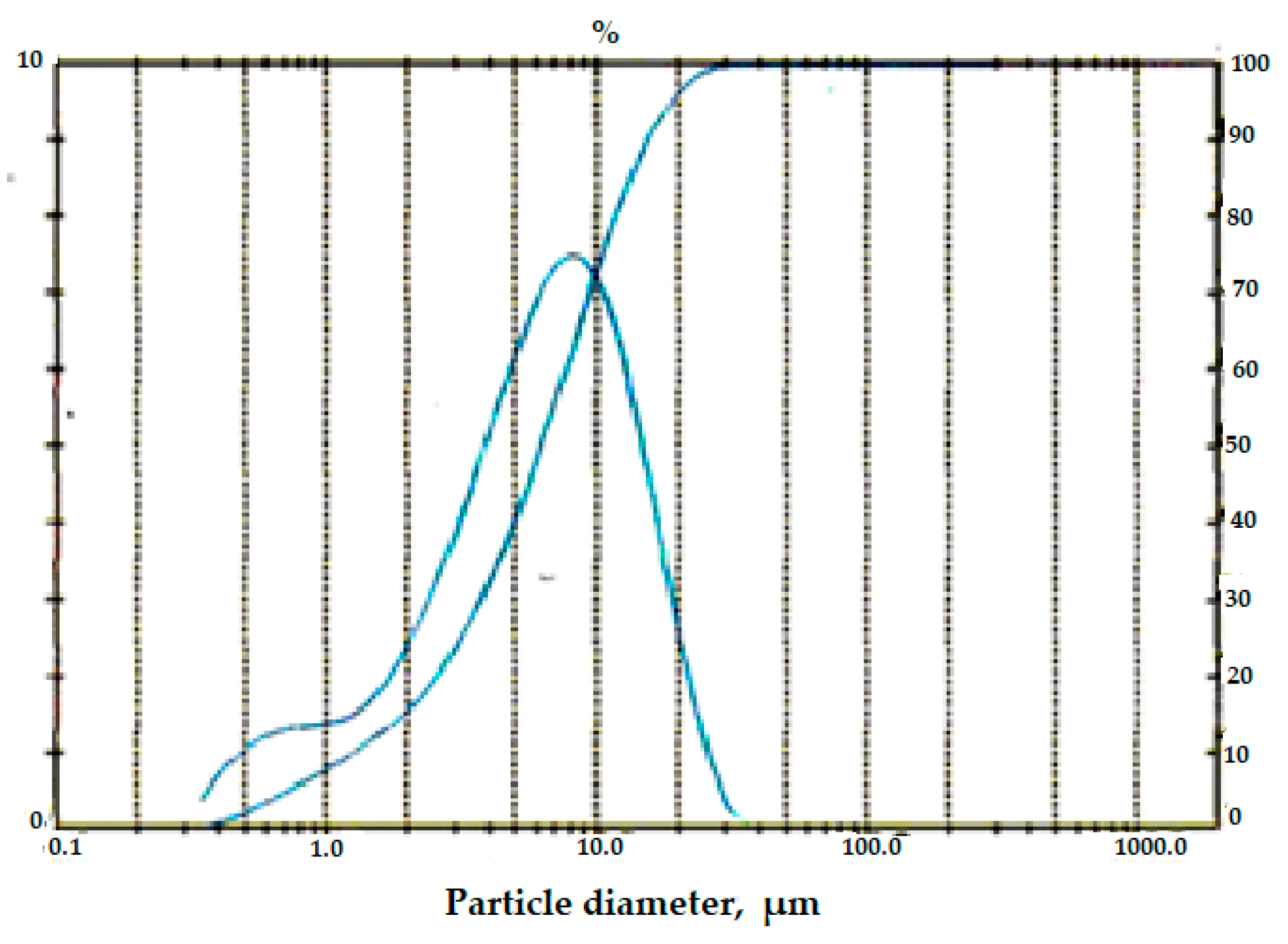
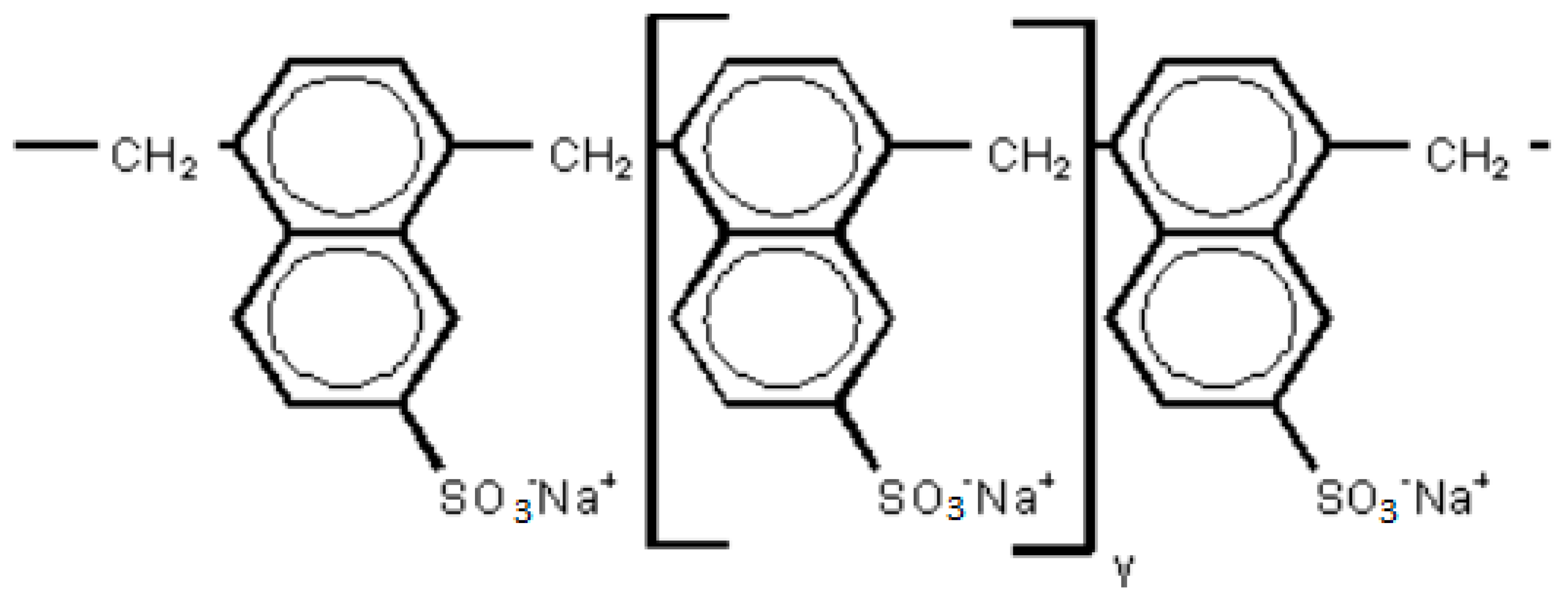
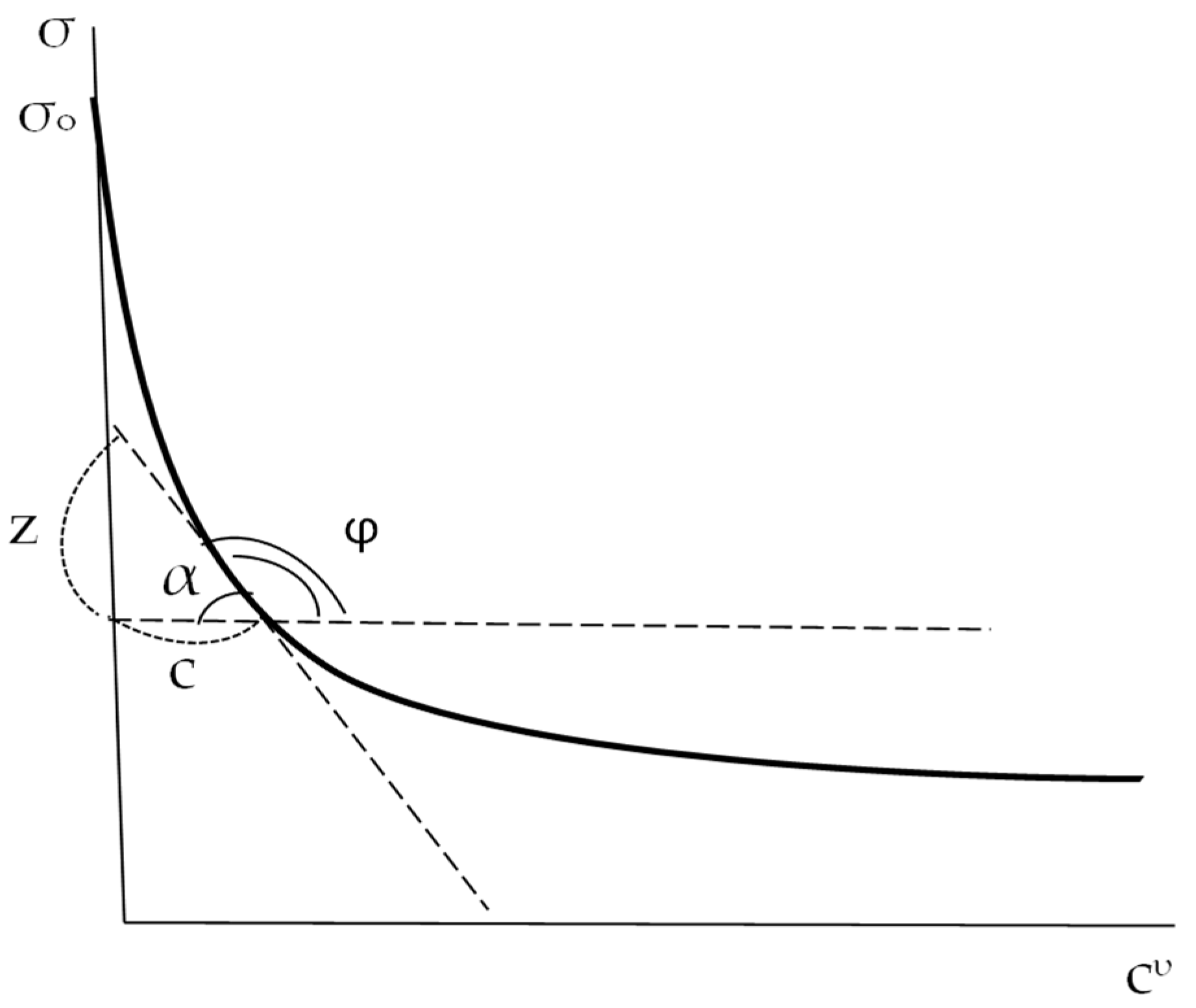
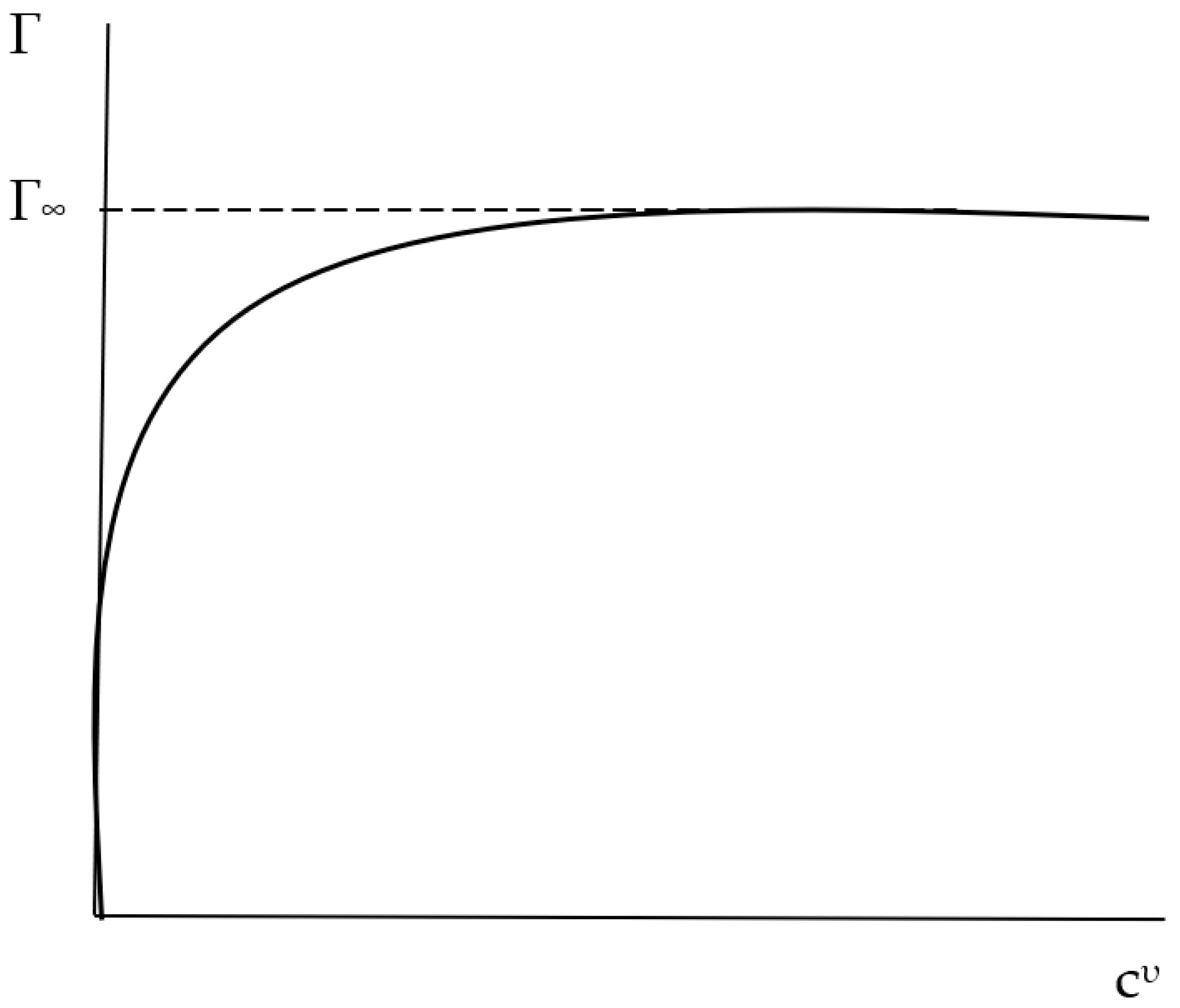
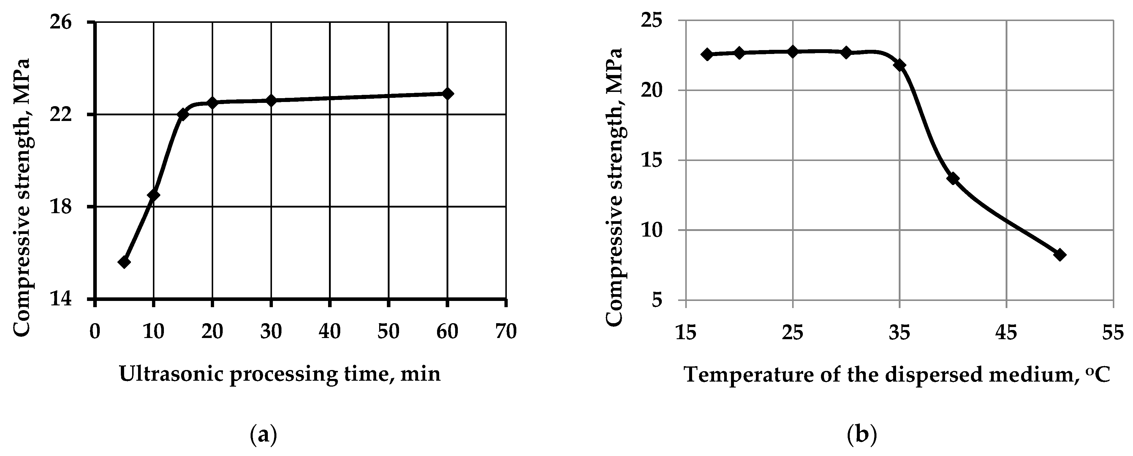
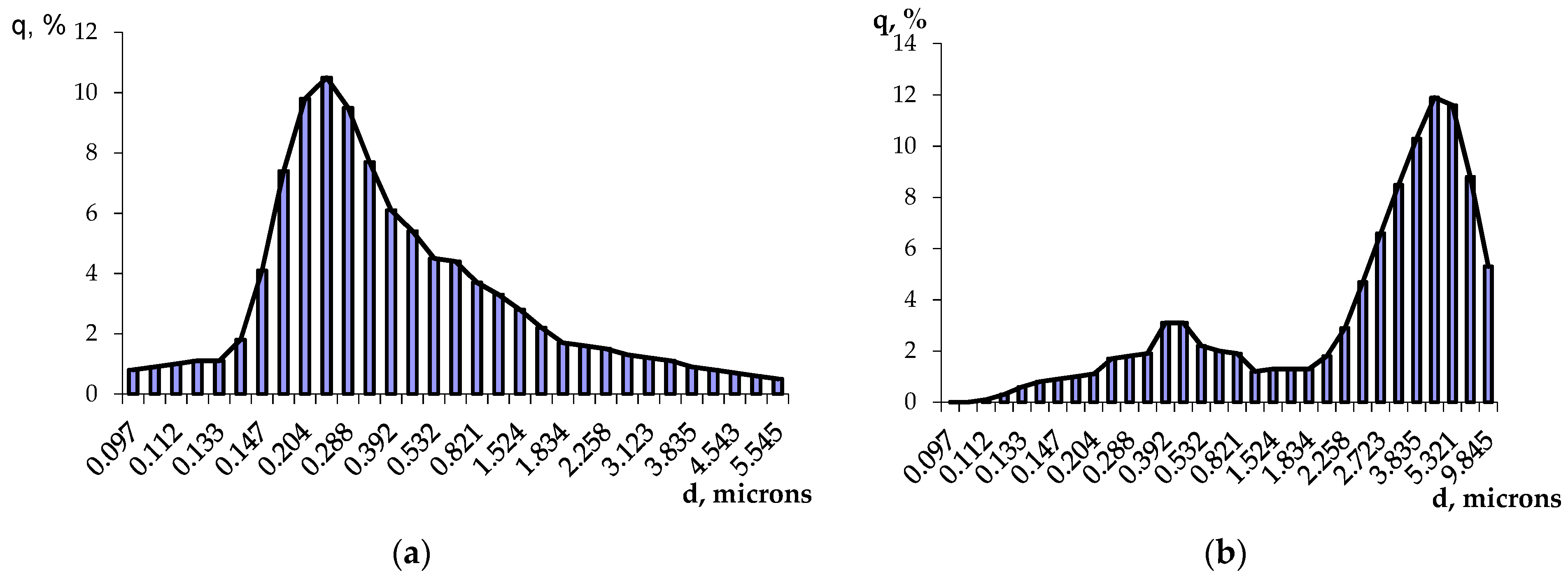
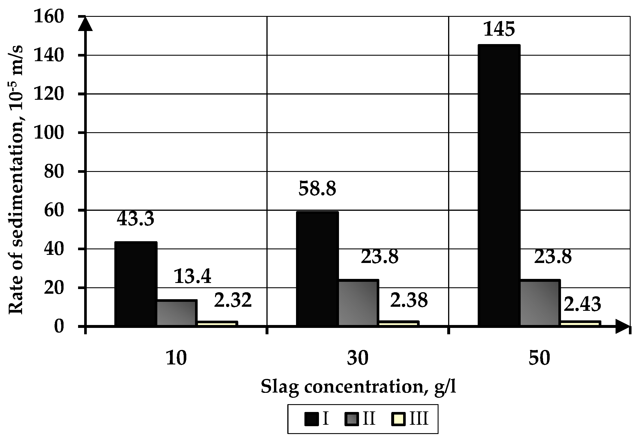
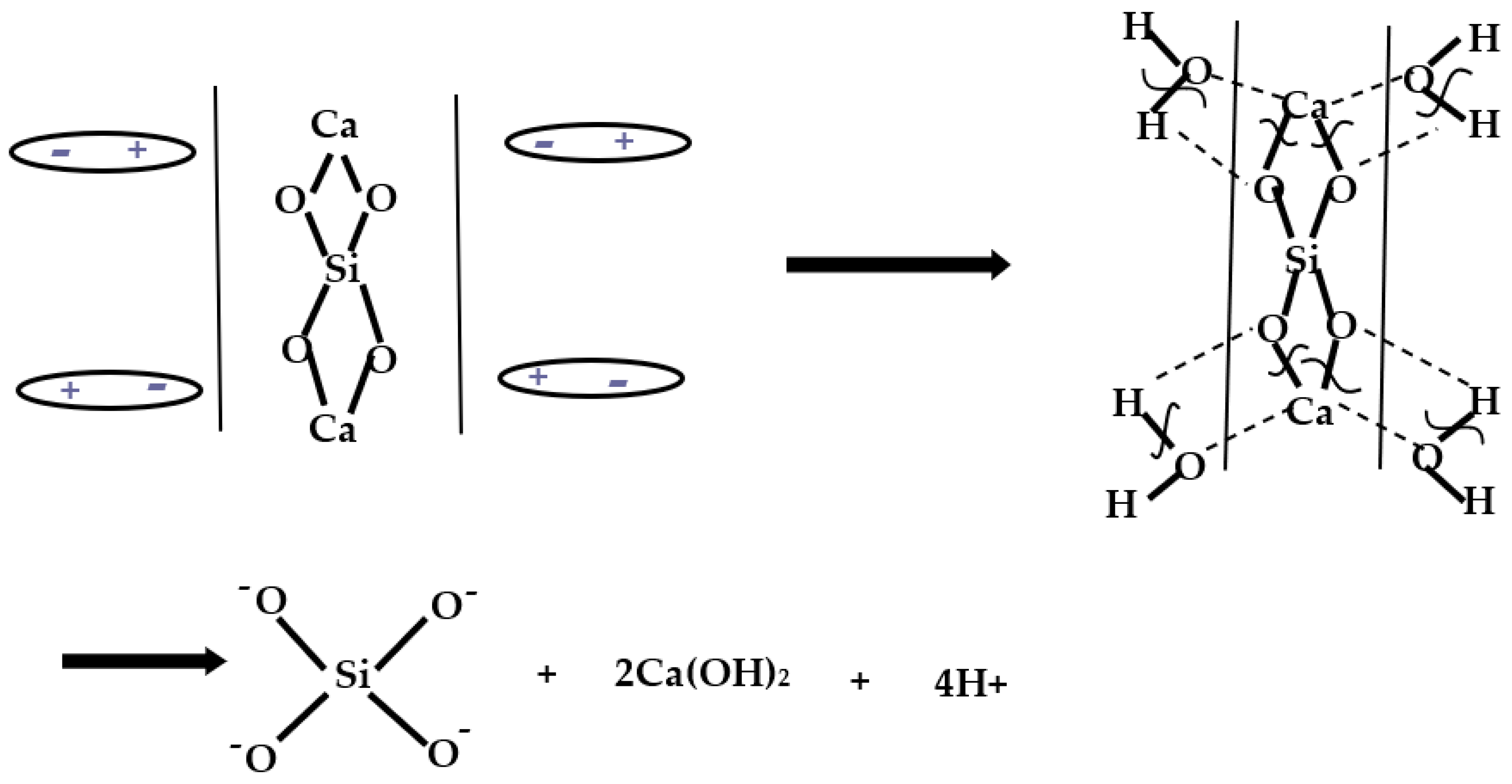
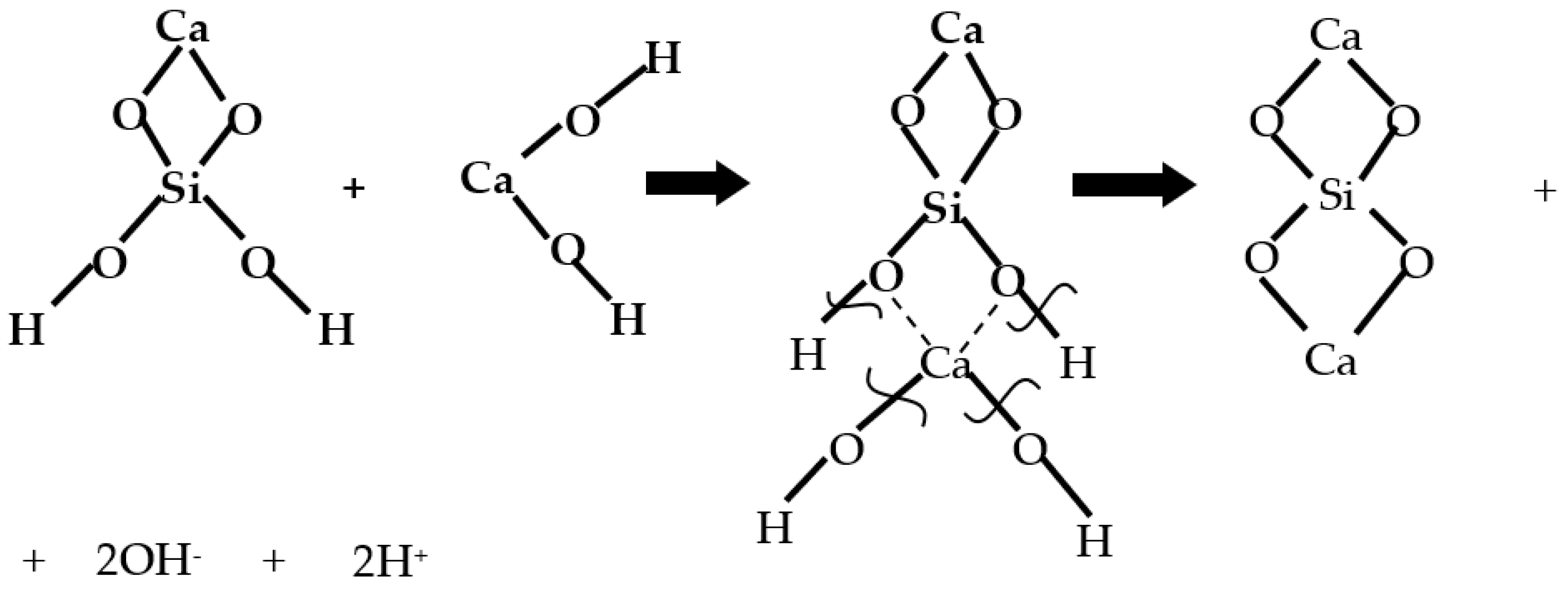
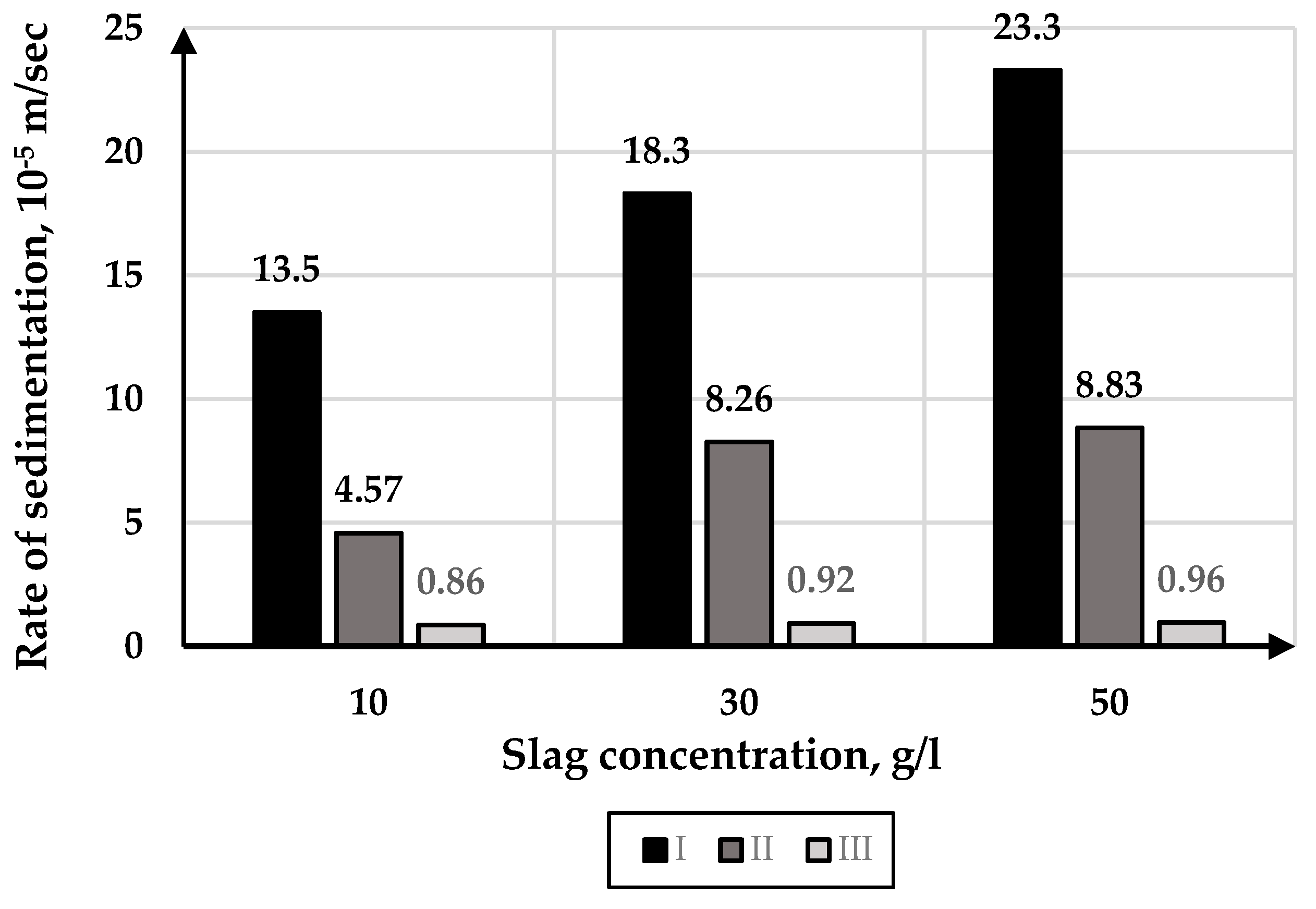
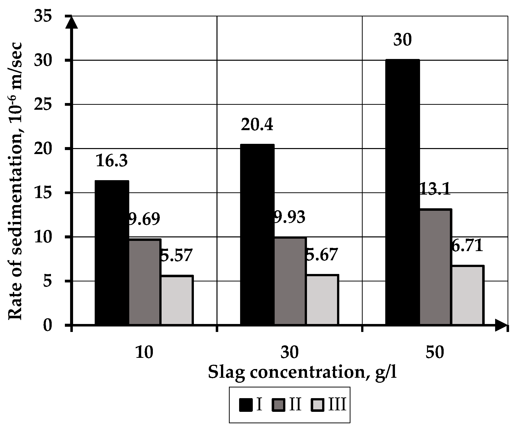
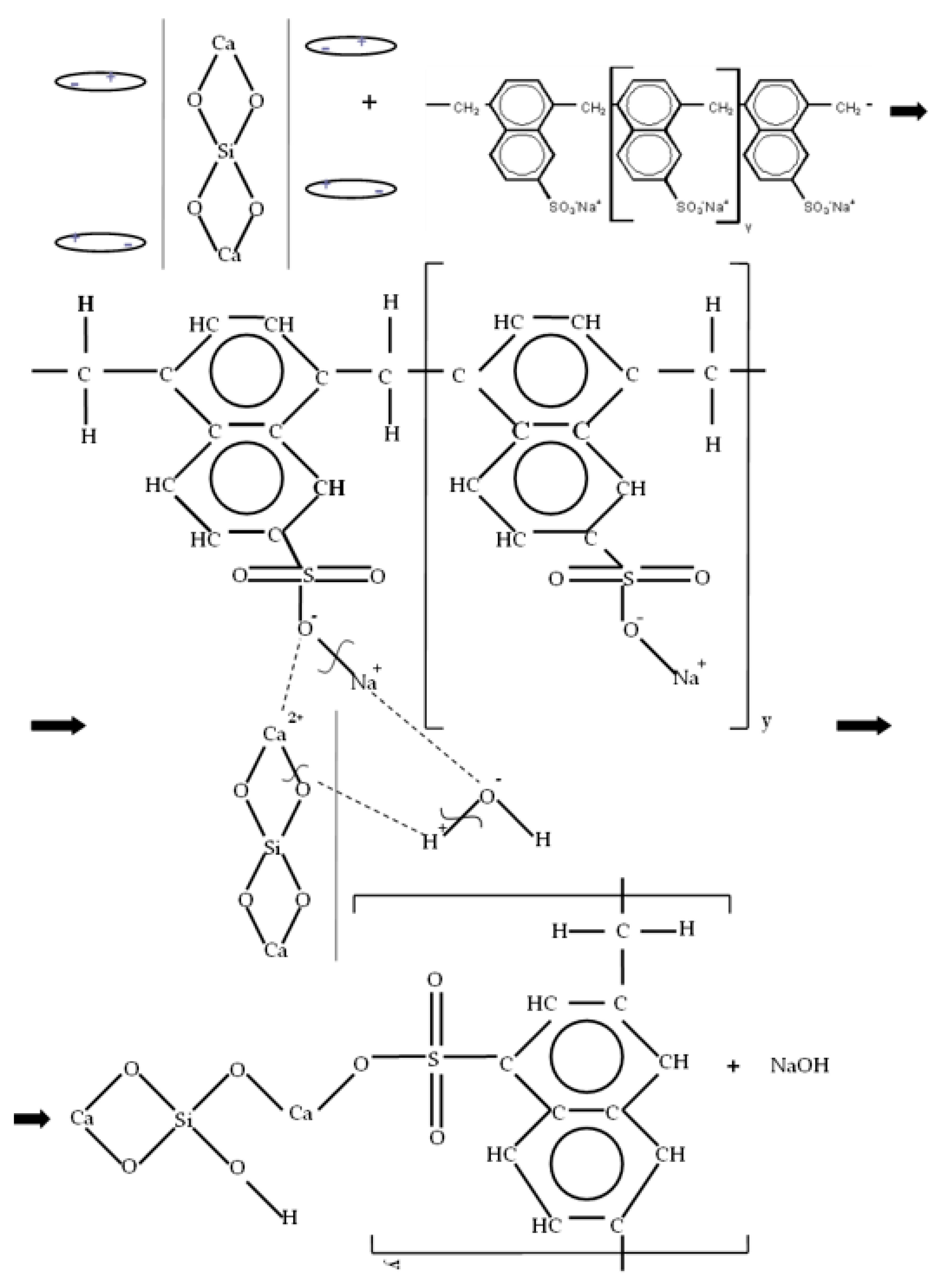
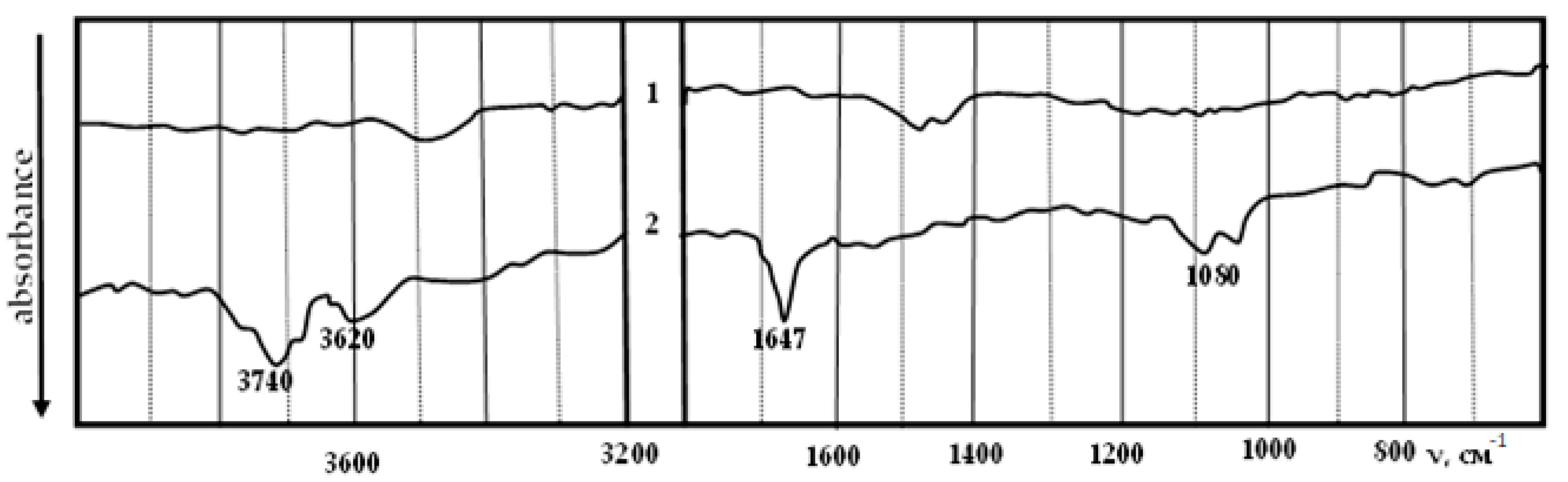
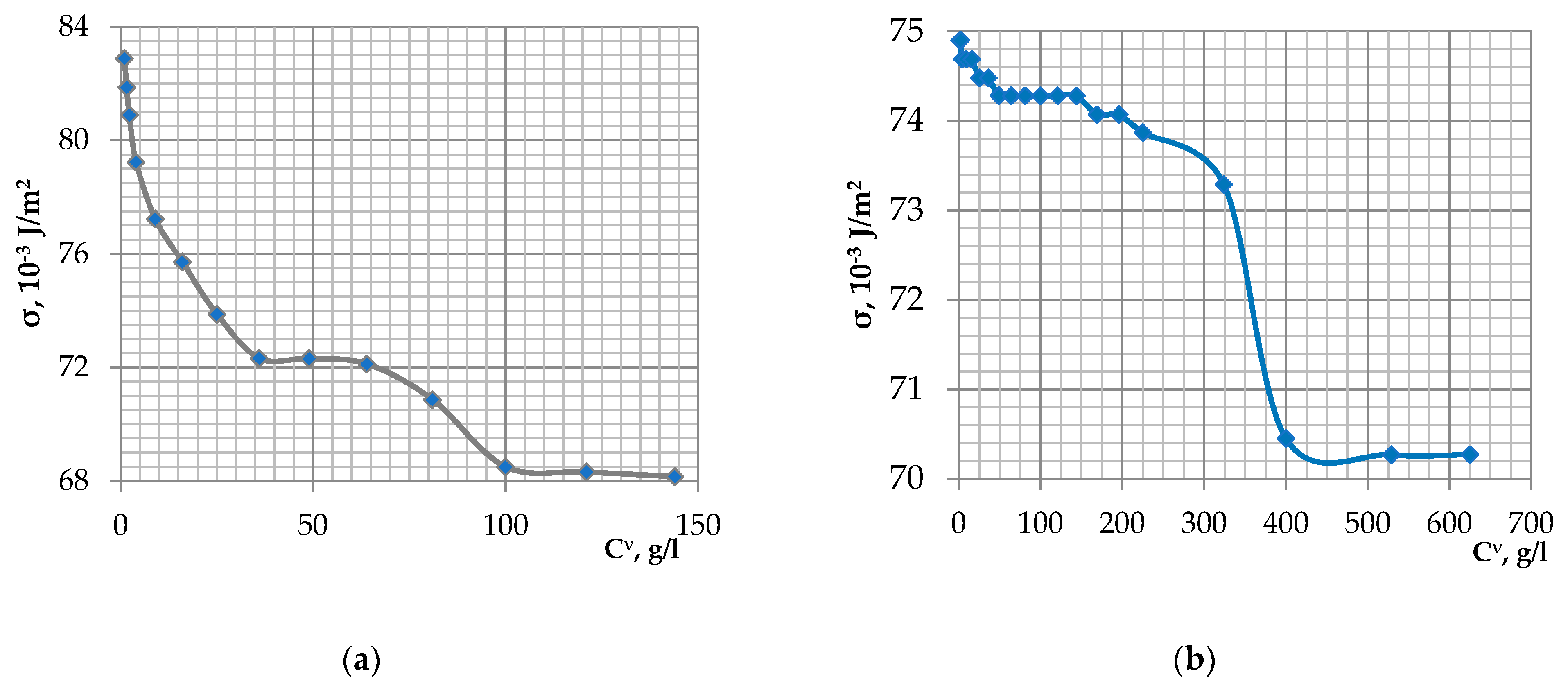
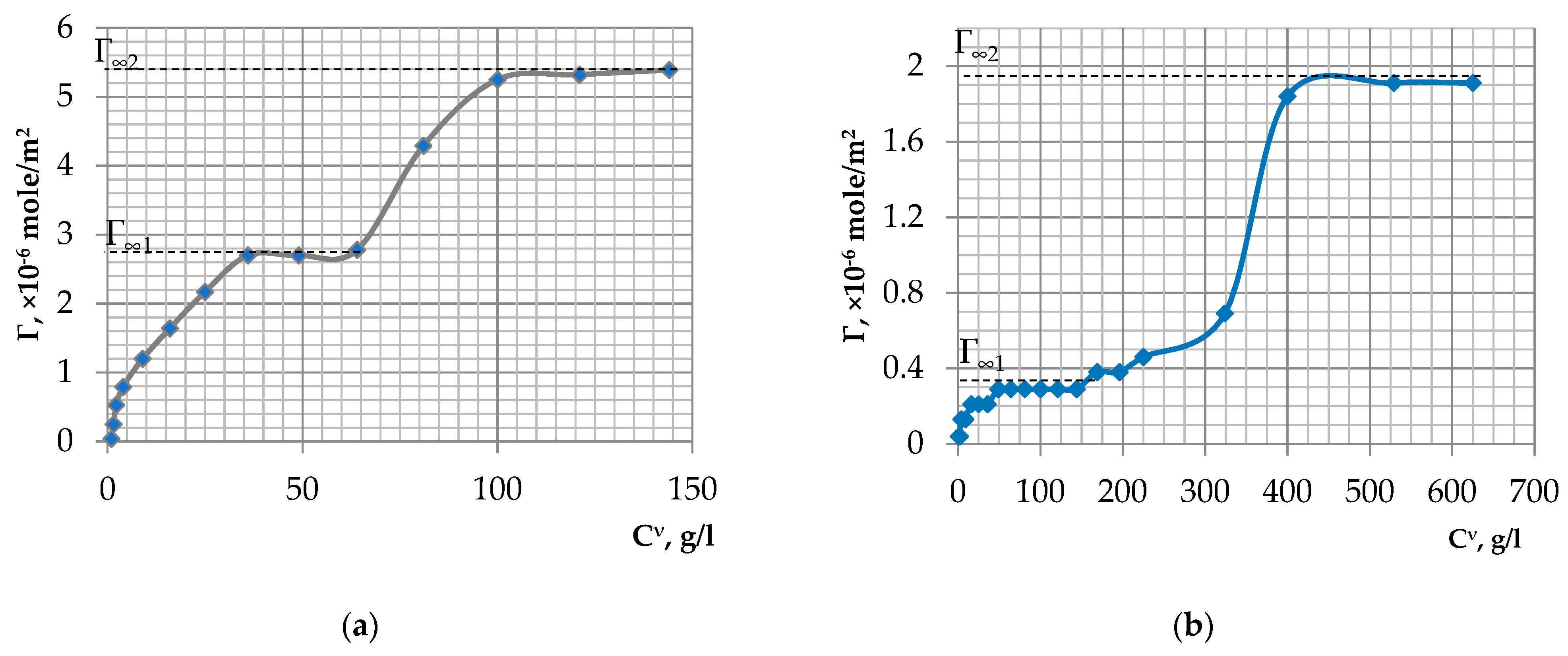
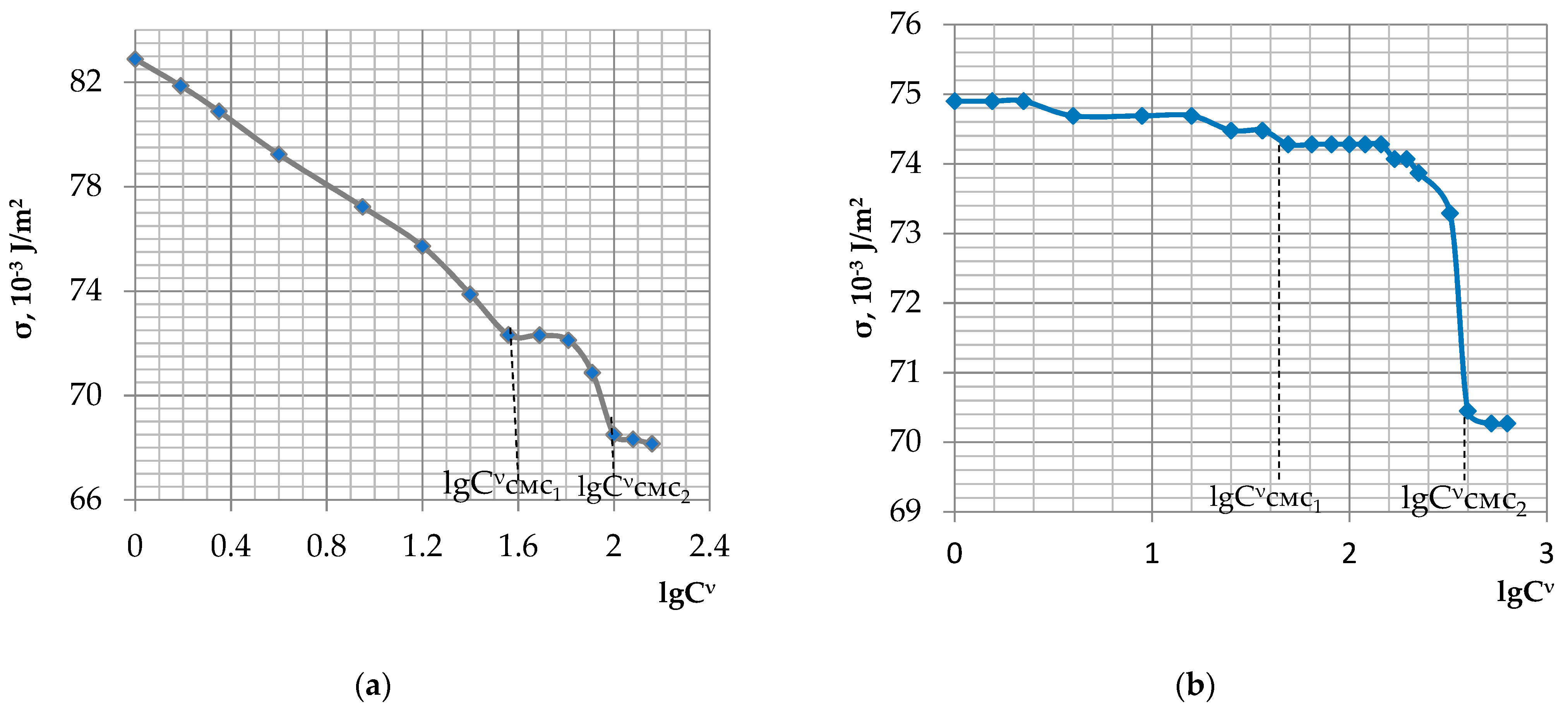
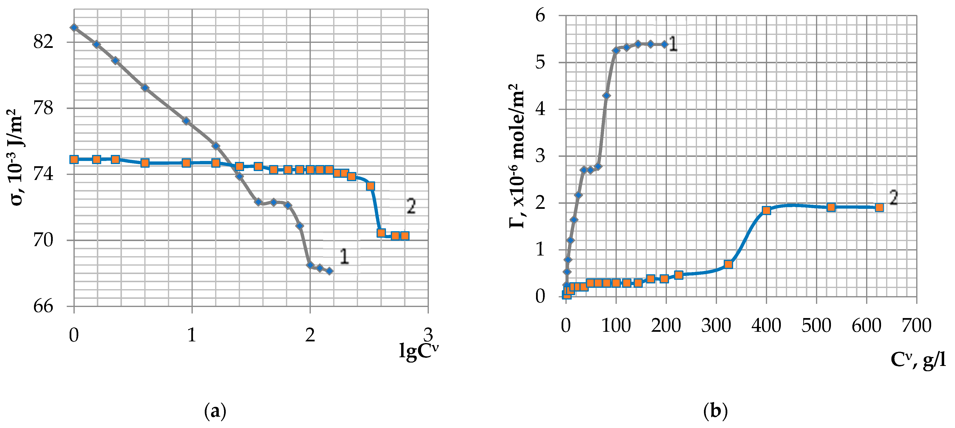
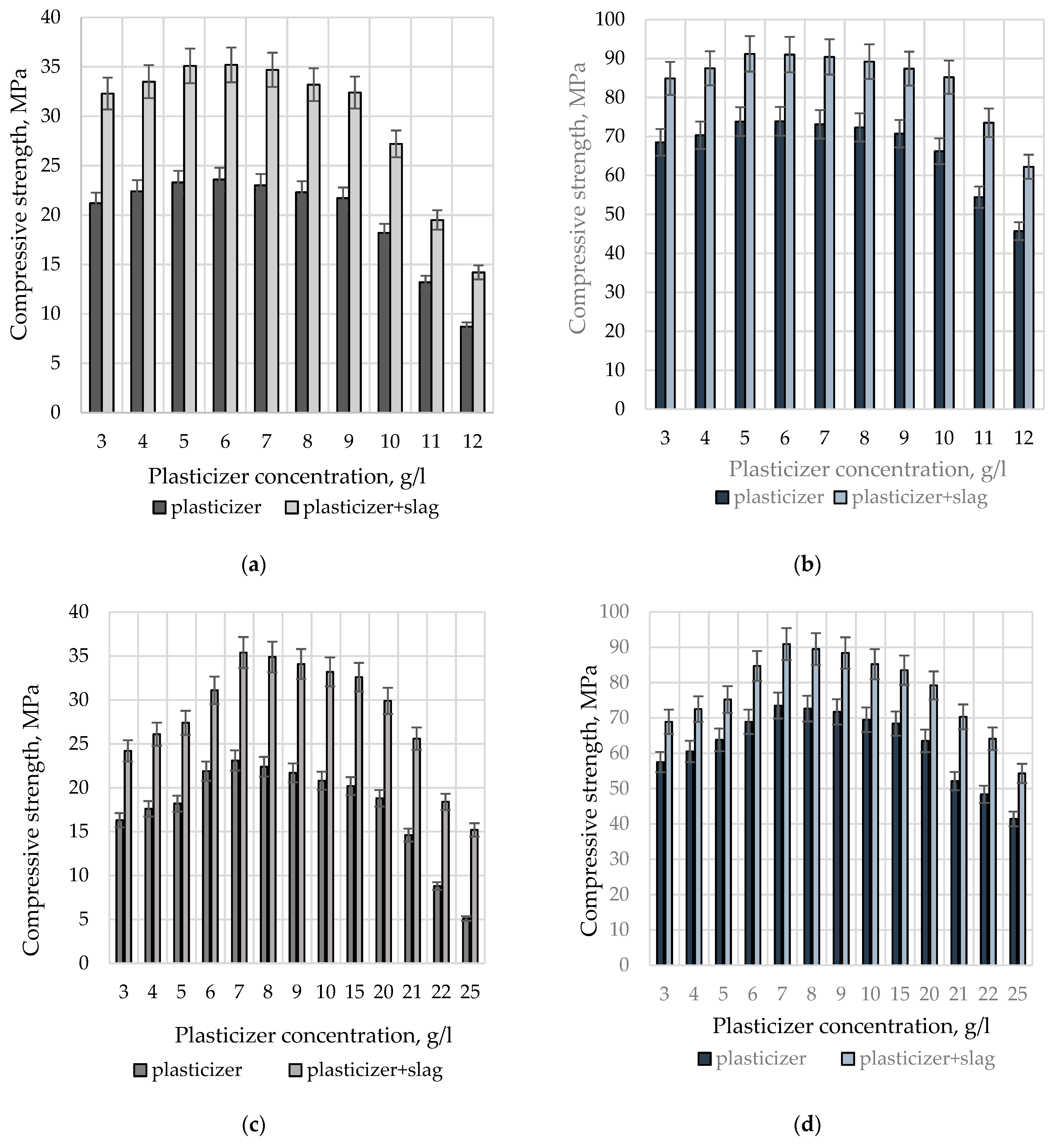
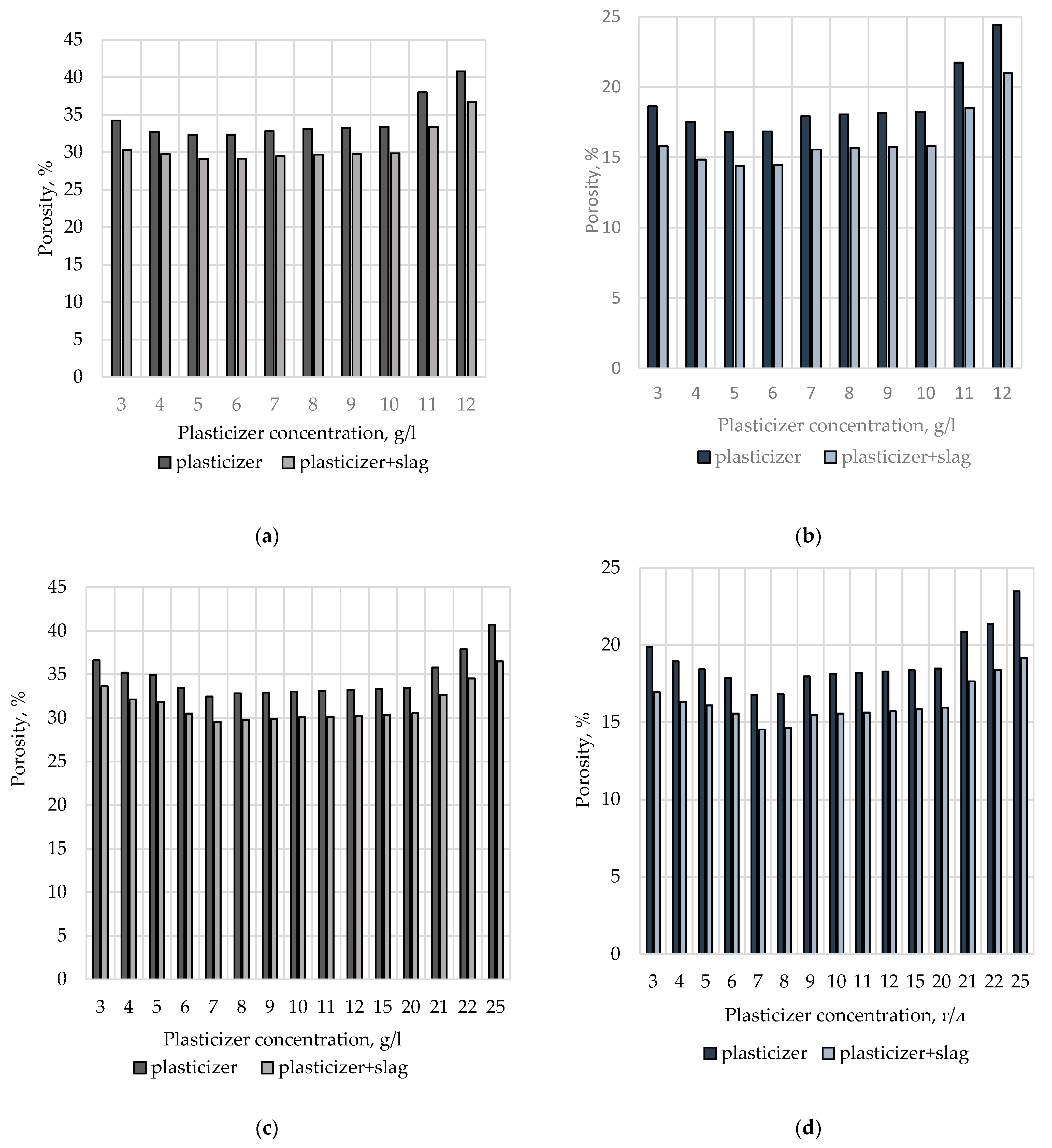
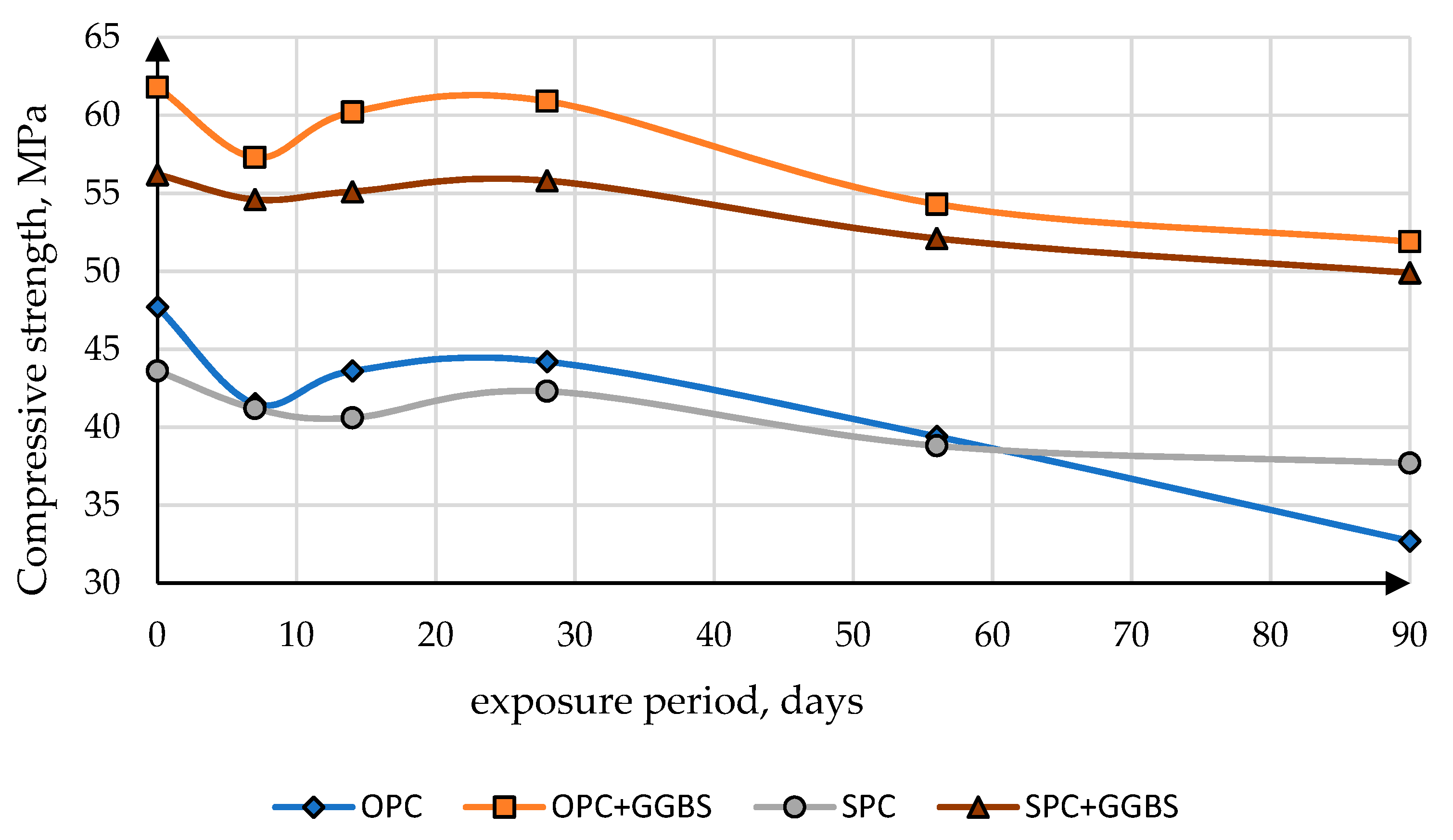
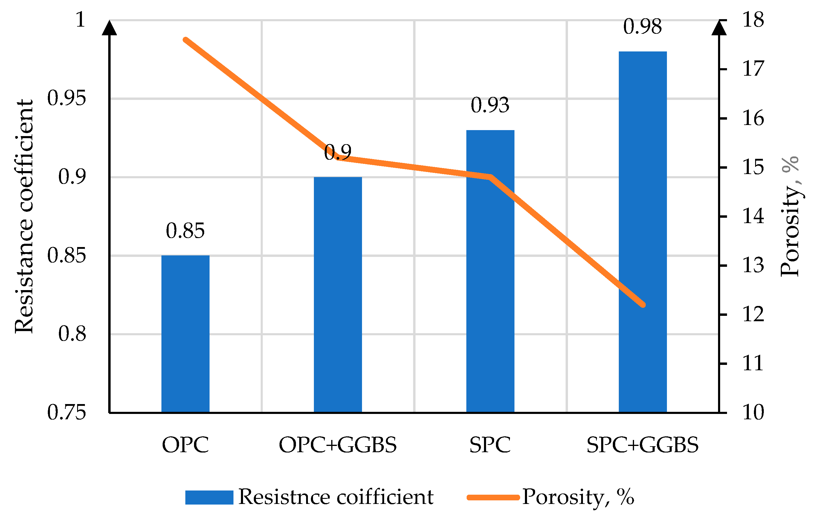
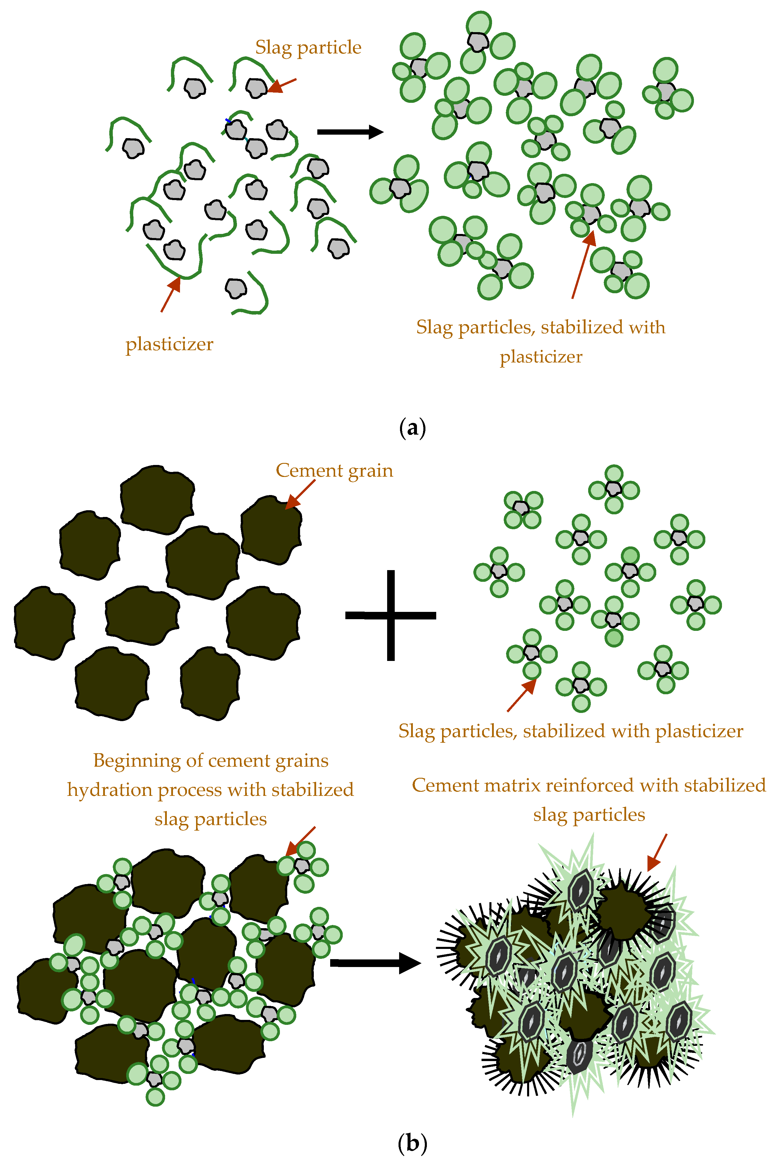
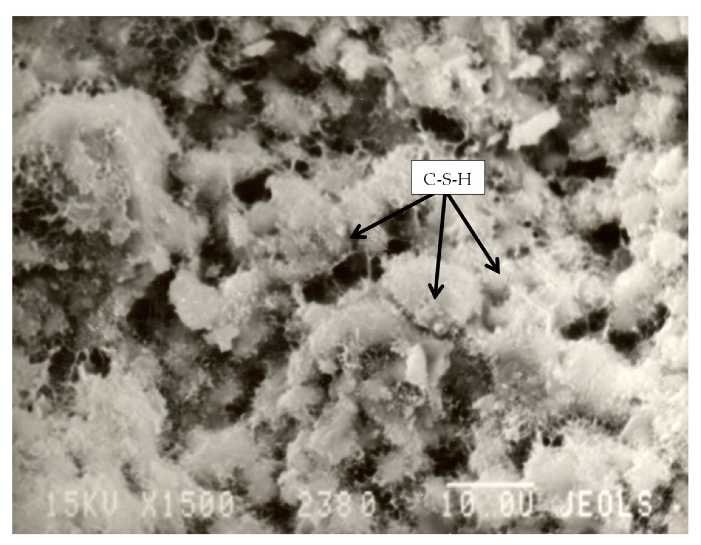
Table 1.
Clinker chemical composition.
| Components | Mass Loss after Calcination | CaO | SiO2 | Al2O3 | Fe2O3 | MgO | SO3 | R2O |
|---|---|---|---|---|---|---|---|---|
| Clinker | 0.81 | 62.65 | 20.10 | 4.46 | 8.62 | 1.85 | 0.57 | 0.94 |
Table 2.
Clinker mineralogical composition.
| Mineral Content, % | |||
|---|---|---|---|
| C3S | C2S | C3A | C4AF |
| 60.00 | 21.00 | 3.00 | 12.00 |
Table 3.
Chemical composition of gypsum stone.
| Components | Mass Loss after Calcination | CaO | SiO2 | Al2O3 | Fe2O3 | MgO | SO3 | MnO | TiO2 | Na2O | K2O | Cl− |
|---|---|---|---|---|---|---|---|---|---|---|---|---|
| Content, % | 22.18 | 31.84 | 2.08 | 0.27 | 0.26 | 1.74 | 40.91 | 0.006 | 0.022 | 0.03 | 0.16 | 0.007 |
Table 4.
GGBS characteristics.
| Chemical composition, % | CaO | SiO2 | Al2O3 | MgO | Fe2O3 + FeO | other |
| 45.40 | 38.20 | 8.10 | 3.20 | 0.80 | 4.30 | |
| Phase composition, % | glass | Crystalline phase | ||||
| 93.20 | 6.80 | |||||
| Alkali modulus, % | 1.10 | |||||
Table 5.
Granulometris composition of GGBS.
| Particle Size, μm | Fraction Content, mass.% |
|---|---|
| 0–1 | 9 |
| 1–5 | 37 |
| 5–7 | 17 |
| 7–10 | 14 |
| 10–15 | 10 |
| 15–20 | 8 |
| 20–30 | 5 |
Table 6.
Superplasticizer characteristics.
| Parameter | Requirement |
|---|---|
| Color, type | Brown powder |
| Mass fraction of dry substance, % | ≥90.0 |
| Chloride content, % | ≤0.1 |
| pH | 8.0 ± 1 |
Table 7.
pH of the dispersed medium in the “slag-water” system.
| Period of pH Measurement | Slag Concentration, g/L | pH of Dispersed Media in Slag Suspensions | |
|---|---|---|---|
| Without Ultrasonic Treatment | After Ultrasonic Treatment | ||
| - | - | 7.6 | |
| After homogenization | 10 | 7.82 | 7.98 |
| 30 | 8.02 | 8.13 | |
| 50 | 8.08 | 8.20 | |
| In 24 h after homogenization | 10 | 7.72 | 7.90 |
| 30 | 7.52 | 8.01 | |
| 50 | 7.24 | 8.05 | |
Table 8.
Comparison of slag particles sedimentation rates in water medium after ultrasonic processing and without it.
Table 8.
Comparison of slag particles sedimentation rates in water medium after ultrasonic processing and without it.
| Slag Concentration, g/L | Vwithout ultrasonic/Vafter ultrasonic | ||
|---|---|---|---|
| I | II | III | |
| 10 | 3.20 | 2.93 | 2.70 |
| 30 | 3.21 | 2.88 | 2.59 |
| 50 | 6.22 | 2.70 | 2.53 |
Table 9.
Comparison of strength characteristics of samples with slag suspension under different conditions of ultrasonic processing.
Table 9.
Comparison of strength characteristics of samples with slag suspension under different conditions of ultrasonic processing.
| Conditions of Preparation | Slag Concentration, g/L | Compressive Strength, MPa | |||||||
|---|---|---|---|---|---|---|---|---|---|
| 1 Day | 3 Day | 7 Day | 28 Day | ||||||
| Rc | σ, % | Rc | σ, % | Rc | σ, % | Rc | σ, % | ||
| - | - | 18.2 | ±4.0 | 23.3 | ±4.0 | 35.2 | ±4.0 | 62.8 | ±4.0 |
| Mechanical mixing | 10 | 20.4 | ±4.0 | 33.8 | ±4.0 | 42.4 | ±4.0 | 75.6 | ±4.0 |
| 30 | 20.3 | ±4.0 | 33.9 | ±4.0 | 42.2 | ±4.0 | 76.7 | ±4.0 | |
| 50 | 19.7 | ±4.0 | 31.5 | ±4.0 | 40.1 | ±4.0 | 74.0 | ±4.0 | |
| Ultrasonic processing (ν = 44 kHz, τ = 15 min; Tdispersed medium = 25 °C) | 10 | 22.8 | ±4.0 | 37.9 | ±4.0 | 45.7 | ±4.0 | 78.8 | ±4.0 |
| 30 | 22.5 | ±4.5 | 38.3 | ±4.0 | 46.2 | ±4.0 | 79.9 | ±4.0 | |
| 50 | 21.3 | ±4.5 | 35.5 | ±4.0 | 44.1 | ±4.0 | 77.1 | ±4.0 | |
| Ultrasonic processing (ν = 44 kHz, τ = 15 min; Tdispersed medium = 40 °C) | 10 | 19.8 | ±4.5 | 30.1 | ±4.0 | 40.1 | ±4.0 | 74.5 | ±4.0 |
| 30 | 19.5 | ±4.5 | 30.7 | ±4.0 | 41.0 | ±4.0 | 74.0 | ±4.0 | |
| 50 | 18.3 | ±4.5 | 28.9 | ±4.0 | 39.5 | ±4.0 | 72.2 | ±4.0 | |
| Ultrasonic processing (ν = 44 kHz, τ = 15 min; Tdispersed medium = 50 °C) | 10 | 14.4 | ±4.5 | 22.3 | ±4.0 | 35.7 | ±4.0 | 66.6 | ±4.0 |
| 30 | 14.1 | ±4.5 | 23.6 | ±4.0 | 38.4 | ±4.0 | 69.2 | ±4.0 | |
| 50 | 13.4 | ±4.5 | 20.2 | ±4.0 | 35.5 | ±4.0 | 69.9 | ±4.0 | |
Table 10.
Time and rate of sedimentation of slag particles in water medium after ultrasonic processing under improper conditions.
Table 10.
Time and rate of sedimentation of slag particles in water medium after ultrasonic processing under improper conditions.
| T, °C | Slag Concentration, g/L | Period of Sedimentation | |||||
|---|---|---|---|---|---|---|---|
| I | II | III | |||||
| Time of Sedimentation, min | Rate of Sedimentation, 10−5 m/s | Time of Sedimentation, min | Rate of Sedimentation, 10−5 m/s | Time of Sedimentation, h-min | Rate of Sedimentation, 10−5 m/s | ||
| 40 °C | 10 | 12 | 21.3 | 44 | 5.80 | 3-20 | 1.28 |
| 30 | 8 | 31.9 | 23 | 10.87 | 3-00 | 1.42 | |
| 50 | 4 | 63.8 | 20 | 12.75 | 2-45 | 1.55 | |
| 50 °C | 10 | 9 | 23.2 | 38 | 6.71 | 3-00 | 1.42 |
| 30 | 6 | 42.5 | 19 | 13.42 | 2-40 | 1.59 | |
| 50 | 3 | 85.0 | 16 | 15.93 | 2-10 | 1.96 | |
Table 11.
Sedimentation stability of slag suspension without ultrasonic processing.
| Parameter | Number of Cylinder | |||||||||
|---|---|---|---|---|---|---|---|---|---|---|
| 1 | 2 | 3 | 4 | 5 | 6 | 7 | 8 | 9 | 10 | |
| Plasticizer concentration, g/L | 1 | 2 | 3 | 4 | 5 | 6 | 7 | 8 | 9 | 10 |
| Protective number of suspension, ×10−3 g/L | 0.8 | 3.4 | 7.5 | 13.2 | 21 | 30 | 41 | 54 | 67.5 | 83 |
| End of complete sedimentation, h-min | 2-30 | 3-40 | 4-50 | 5-20 | 6-30 | 6-40 | 6-40 | 6-50 | 6-50 | 7-00 |
Table 12.
Comparative analysis of the sedimentation rates of slag in water and water-polymer dispersed medium.
Table 12.
Comparative analysis of the sedimentation rates of slag in water and water-polymer dispersed medium.
| Slag Concentration, g/L | Vwithout plasricizer /Vwith plasricizer | ||
|---|---|---|---|
| I | II | III | |
| 10 | 26.6 | 13.8 | 4.2 |
| 30 | 28.8 | 24.0 | 4.2 |
| 50 | 48.3 | 18.2 | 3.6 |
Table 13.
pH values of the dispersed medium in the “slag-water-plasticizer” system.
| Period of pH Measurement | Slag Concentration, g/L | pH of Dispersed Medium | |
|---|---|---|---|
| Without Plasticizer | With Plasticizer | ||
| - | - | 7.6 | - |
| - | - | - | 8.06 |
| After homogenization | 10 | 7.82 | 8.11 |
| 30 | 8.02 | 8.13 | |
| 50 | 8.08 | 8.16 | |
| In 24 h after homogenization | 10 | 7.72 | 7.99 |
| 30 | 7.52 | 7.99 | |
| 50 | 7.24 | 8.02 | |
Table 14.
Comparative analysis of the sedimentation rates of slag particles in a water-polymer suspension after and without ultrasonic processing.
Table 14.
Comparative analysis of the sedimentation rates of slag particles in a water-polymer suspension after and without ultrasonic processing.
| Slag Concentration, g/L | Vwithout ultrasonic proc./Vafter ultrasonic proc. | ||
|---|---|---|---|
| I | II | III | |
| 10 | 5.25 | 7.81 | 4.64 |
| 30 | 5.17 | 3.44 | 4.73 |
| 50 | 5.89 | 3.80 | 4.33 |
Table 15.
pH values of the dispersed medium in water-polymer slag suspensions.
| Period of pH Measurement | Slag Concentration, g/L | pH of Dispersed Medium | |
|---|---|---|---|
| Without Ultrasonic Proc. | After Ultrasonic Proc. | ||
| - | - | 8.06 | - |
| After homogenization | 10 | 8.11 | 8.34 |
| 30 | 8.13 | 8.37 | |
| 50 | 8.16 | 8.42 | |
| In 24 h after homogenization | 10 | 7.99 | 8.36 |
| 30 | 7.99 | 8.38 | |
| 50 | 8.02 | 8.41 | |
Table 16.
Water characteristics.
| Parameter | Water No. 1 | Water No. 2 |
|---|---|---|
| pH | 7.6 | 7.0 |
| Hardness, mg-ekv/L | 2.8 | 22.5 |
| Fe, mg/L | 0.38 | 0.15 |
Table 17.
Time and rate of sedimentation of slag particles in water dispersed media of different hardness without ultrasonic processing.
Table 17.
Time and rate of sedimentation of slag particles in water dispersed media of different hardness without ultrasonic processing.
| Water | Slag Concentration, g/L | Period of Sedimentation | |||||
|---|---|---|---|---|---|---|---|
| I | II | III | |||||
| Time of Sedimentation, min-s | Rate of Sedimentation, 10−5 m/s | Time of Sedimentation, min | Rate of Sedimentation, 10−5 m/s | Time of Sedimentation, min | Rate of Sedimentation, 10−5 m/s | ||
| No. 1 | 10 | 6-00 | 43.3 | 19 | 13.4 | 115 | 2.32 |
| 30 | 3-55 | 58.8 | 12 | 23.8 | 110 | 2.38 | |
| 50 | 2-10 | 145.0 | 12 | 23.8 | 105 | 2.43 | |
| No. 2 | 10 | 5-40 | 47.1 | 17 | 15.7 | 110 | 2.42 |
| 30 | 3-40 | 72.7 | 10 | 26.7 | 105 | 2.54 | |
| 50 | 1-50 | 145.0 | 9 | 29.6 | 100 | 2.67 | |
Table 18.
Time and rate of sedimentation of slag particles in water dispersed media of different hardness after ultrasonic processing.
Table 18.
Time and rate of sedimentation of slag particles in water dispersed media of different hardness after ultrasonic processing.
| Water | Slag Concentration, g/L | Period of sedimentation | |||||
|---|---|---|---|---|---|---|---|
| I | II | III | |||||
| Time of Sedimentation, min | Rate of Sedimentation, 10−5 m/sec | Time of Sedimentation, min | Rate of Sedimentation, 10−5 m/s | Time of Sedimentation, min | Rate of Sedimentation, 10−5 m/s | ||
| No. 1 | 10 | 19 | 13.5 | 56 | 4.57 | 5-00 | 0.86 |
| 30 | 14 | 18.3 | 31 | 8.26 | 4-40 | 0.92 | |
| 50 | 11 | 23.3 | 29 | 8.83 | 4-30 | 0.96 | |
| No. 2 | 10 | 17 | 15.7 | 53 | 5.05 | 4-50 | 0.92 |
| 30 | 12 | 22.2 | 28 | 9.52 | 4-30 | 0.99 | |
| 50 | 9 | 29.6 | 26 | 10.26 | 4-20 | 1.03 | |
Table 19.
Time and rate of sedimentation of slag particles in water dispersed medium of different hardness with plasticizer without ultrasonic processing.
Table 19.
Time and rate of sedimentation of slag particles in water dispersed medium of different hardness with plasticizer without ultrasonic processing.
| Water | Slag Concentration, g/L | Period of Sedimentation | |||||
|---|---|---|---|---|---|---|---|
| I | II | III | |||||
| Time of Sedimentation, h-min | Rate of Sedimentation, 10−6 m/s | Time of Sedimentation, h-min | Rate of Sedimentation, 10−6 m/s | Time of Sedimentation, h-min | Rate of Sedimentation, 10−6 m/s | ||
| No. 1 | 10 | 2-40 | 16.3 | 4-30 | 9.69 | 7-50 | 5.57 |
| 30 | 2-00 | 20.4 | 4-00 | 9.93 | 7-00 | 5.67 | |
| 50 | 1-50 | 30 | 3-20 | 13.1 | 6-30 | 6.71 | |
| No. 2 | 10 | 0-40 | 61.0 | 2-00 | 22.2 | 5-20 | 8.33 |
| 30 | 0-25 | 106.7 | 1-30 | 29.6 | 4-40 | 9.52 | |
| 50 | 0-18 | 148.1 | 1-00 | 44.4 | 4-10 | 10.67 | |
Table 20.
Time and rate of sedimentation of slag particles in water dispersed medium of different hardness with plasticizer after ultrasonic processing.
Table 20.
Time and rate of sedimentation of slag particles in water dispersed medium of different hardness with plasticizer after ultrasonic processing.
| Water | Slag Concentration, g/L | Period of Sedimentation | |||||
|---|---|---|---|---|---|---|---|
| I | II | III | |||||
| Time of Sedimentation, h-min | Rate of Sedimentation, 10−6 m/s | Time of Sedimentation, h-min | Rate of Sedimentation, 10−6 m/s | Time of Sedimentation, h-min | Rate of Sedimentation, 10−6 m/s | ||
| No. 1 | 10 | 14-00 | 3.10 | 24-00 | 1.81 | 45-00 | 0.96 |
| 30 | 11-00 | 3.94 | 15-00 | 2.89 | 40-00 | 1.09 | |
| 50 | 8-00 | 5.10 | 11-40 | 3.45 | 28-00 | 1.55 | |
| No. 2 | 10 | 3-30 | 12.7 | 9-00 | 4.94 | 30-00 | 1.48 |
| 30 | 2-30 | 17.8 | 6-30 | 6.84 | 25-00 | 1.78 | |
| 50 | 1-40 | 26.7 | 5-50 | 7.62 | 18-00 | 2.47 | |
Table 21.
Plasticizer solutions concentrations for the evaluation of its surface-active properties.
| Water | Plasticizer Concentration, g/L | ||||||||||||||||||||
|---|---|---|---|---|---|---|---|---|---|---|---|---|---|---|---|---|---|---|---|---|---|
| No. 1 | 1 | 1.25 | 1.5 | 2 | 3 | 4 | 5 | 6 | 7 | 8 | 9 | 10 | 11 | 12 | - | - | - | - | - | - | - |
| No. 2 | 1 | 1.25 | 1.5 | 2 | 3 | 4 | 5 | 6 | 7 | 8 | 9 | 10 | 11 | 12 | 13 | 14 | 15 | 18 | 20 | 23 | 25 |
Table 22.
Characteristics of plasticizer solutions.
| Water | lgCν at CMC1/CMC2 | CMC1/CMC2, g/L | g±, ×10−4 J·m/mole | Γ × 10−6 mole/m2 at CMC1/CMC2 | Γ∞1/Γ∞2, ×10−6 mole/m2 |
|---|---|---|---|---|---|
| 1 | 1.56/2 | 6/10 | 7.39 | 2.7/5.25 | 2.78/5.39 |
| 2 | 1.69/2.6 | 7/20 | 0.71 | 0.29/1.84 | 0.29/1.91 |
Table 23.
Construction and technical properties of cement mortar based on OPC with slag suspension.
| Dispersed Medium | Slag Concentration, g/l | Normal Consistency, % | Setting Time | ||||
|---|---|---|---|---|---|---|---|
| Without Ultrasonic Processing | After Ultrasonic Processing | Without Ultrasonic Processing | After Ultrasonic Processing | ||||
| Initial | Final | Initial | Final | ||||
| h-min | h-min | h-min | h-min | ||||
| Water | 0 | 25.0 | - | 2-40 | 5-00 | - | - |
| 10 | 25.0 | 25.0 | 3-05 | 5-35 | 3-00 | 5-30 | |
| 30 | 25.5 | 25.5 | 3-15 | 5-40 | 3-10 | 5-30 | |
| 50 | 25.5 | 25.5 | 4-05 | 6-05 | 3-30 | 5-45 | |
| Water-plasticizer * | 0 | 23.0 | 23.0 | 2-30 | 4-50 | 2-30 | 4-50 |
| 10 | 23.5 | 24.0 | 3-10 | 5-20 | 2-40 | 4-55 | |
| 30 | 23.5 | 24.5 | 3-15 | 5-30 | 2-45 | 5-00 | |
| 50 | 24.0 | 24.5 | 3-30 | 5-45 | 3-10 | 5-10 | |
* the concentration of the plasticizer in the slag suspension is 5 g/L.
Table 24.
Construction and technical properties of cement mortar based on SPC with slag suspension.
| Dispersed Medium | Slag Concentration, g/l | Normal Consistency, % | Setting Time | ||||
|---|---|---|---|---|---|---|---|
| Without Ultrasonic Processing | After Ultrasonic Processing | Without Ultrasonic Processing | After Ultrasonic Processing | ||||
| Initial | Final | Initial | Final | ||||
| h-min | h-min | h-min | h-min | ||||
| Water | 0 | 25.0 | - | 2-50 | 3-40 | - | - |
| 10 | 25.0 | 25.5 | 3-00 | 4-10 | 3-00 | 4-05 | |
| 30 | 25.0 | 25.5 | 3-10 | 4-15 | 3-10 | 4-10 | |
| 50 | 25.0 | 25.5 | 3-15 | 4-20 | 3-10 | 4-15 | |
| Water-plasticizer * | 0 | 23.0 | 23.0 | 2-40 | 3-30 | 2-40 | 3-30 |
| 10 | 23.5 | 24.5 | 2-55 | 3-55 | 2-35 | 3-40 | |
| 30 | 23.5 | 24.5 | 3-00 | 4-00 | 2-40 | 3-45 | |
| 50 | 23.5 | 24.5 | 3-10 | 4-10 | 2-50 | 3-50 | |
* the concentration of the plasticizer in the slag suspension is 5 g/L.
Table 25.
Strength characteristics of OPC-based samples with slag suspension.
| Dispersed Medium | Slag Concentration, g/L | Compressive Strength, MPaAge (Days) | |||||||||||||||
|---|---|---|---|---|---|---|---|---|---|---|---|---|---|---|---|---|---|
| Without Ultrasonic Procesing | After Ultrasonic Procesing | ||||||||||||||||
| 1 | 3 | 7 | 28 | 1 | 3 | 7 | 28 | ||||||||||
| Rc | σ, % | Rc | σ, % | Rc | σ, % | Rc | σ, % | Rc | σ, % | Rc | σ, % | Rc | σ, % | Rc | σ, % | ||
| Water | 0 | 18.2 | ±4 | 23.3 | ±4 | 35.2 | ±4 | 62.8 | ±4 | - | - | - | - | - | - | - | - |
| 10 | 20.4 | ±4 | 28.8 | ±4 | 43.4 | ±4 | 77.6 | ±4 | 22.8 | ±4 | 37.9 | ±4 | 45.7 | ±4 | 78.8 | ±4 | |
| 30 | 20.3 | ±4 | 28.9 | ±4 | 44.2 | ±4 | 78.7 | ±4 | 22.5 | ±4 | 38.3 | ±4 | 46.2 | ±4 | 79.9 | ±4 | |
| 50 | 19.6 | ±4 | 27.5 | ±4 | 41.1 | ±4 | 78.0 | ±4 | 21.3 | ±4 | 35.5 | ±4 | 44.1 | ±4 | 77.8 | ±4 | |
| Water-plasticizer * | 0 | 16.1 | ±4 | 29.9 | ±4 | 47.1 | ±4 | 71.1 | ±4 | 16.3 | ±4 | 29.6 | ±4 | 46.6 | ±4 | 71.1 | ±4 |
| 10 | 22.1 | ±4 | 36.8 | ±4 | 49.3 | ±4 | 83.5 | ±4 | 25.9 | ±4 | 44.6 | ±4 | 54.3 | ±4 | 87.8 | ±4 | |
| 30 | 22.9 | ±4 | 36.2 | ±4 | 49.7 | ±4 | 83.2 | ±4 | 26.6 | ±4 | 46.8 | ±4 | 55.0 | ±4 | 88.5 | ±4 | |
| 50 | 21.7 | ±4 | 35.3 | ±4 | 48.2 | ±4 | 82.4 | ±4 | 24.9 | ±4 | 42.9 | ±4 | 51.6 | ±4 | 86.5 | ±4 | |
* the concentration of the plasticizer in the slag suspension is 5 g/L.
Table 26.
Strength characteristics of SPC-based samples with slag suspension.
| Dispersed Medium | Slag Concentration, g/L | Compressive Strength, MPaAge (Days) | |||||||||||||||
|---|---|---|---|---|---|---|---|---|---|---|---|---|---|---|---|---|---|
| Without Ultrasonic Processing | After Ultrasonic Processing | ||||||||||||||||
| 1 | 3 | 7 | 28 | 1 | 3 | 7 | 28 | ||||||||||
| Rc | σ, % | Rc | σ, % | Rc | σ, % | Rc | σ, % | Rc | σ, % | Rc | σ, % | Rc | σ, % | Rc | σ, % | ||
| Water | 0 | 12.5 | ±4 | 16.4 | ±4 | 26.2 | ±4 | 40.2 | ±4 | - | - | - | - | - | - | - | - |
| 10 | 15.1 | ±4 | 28.7 | ±4 | 39.8 | ±4 | 58.2 | ±4 | 17.2 | ±4 | 32.6 | ±4 | 43.4 | ±4 | 63.6 | ±4 | |
| 30 | 15.5 | ±4 | 29.6 | ±4 | 40.3 | ±4 | 61.9 | ±4 | 17.9 | ±4 | 33.4 | ±4 | 44.7 | ±4 | 63.9 | ±4 | |
| 50 | 14.6 | ±4 | 23.1 | ±4 | 39.7 | ±4 | 60.7 | ±4 | 16.8 | ±4 | 29.8 | ±4 | 41.1 | ±4 | 62.5 | ±4 | |
| Water-plasticizer * | 0 | 10.9 | ±4 | 18.2 | ±4 | 31.4 | ±4 | 49.9 | ±4 | 10.8 | ±4 | 18.7 | ±4 | 31.9 | ±4 | 50.5 | ±4 |
| 10 | 17.3 | ±4 | 33.4 | ±4 | 43.3 | ±4 | 64.1 | ±4 | 20.4 | ±4 | 38.7 | ±4 | 46.5 | ±4 | 73.7 | ±4 | |
| 30 | 17.8 | ±4 | 33.9 | ±4 | 42.9 | ±4 | 64.9 | ±4 | 20.5 | ±4 | 39.1 | ±4 | 46.9 | ±4 | 74.9 | ±4 | |
| 50 | 17.0 | ±4 | 31.8 | ±4 | 40.4 | ±4 | 63.3 | ±4 | 19.9 | ±4 | 38.1 | ±4 | 45.7 | ±4 | 73.1 | ±4 | |
* the concentration of the plasticizer in the slag suspension is 5 g/L.
Table 27.
Physical and mechanical characteristics of cement mortar.
| Composition | Flexural Strength (MPa) Age (Days) | Compressive Strength (MPa) Age (Days) | ||||||||||||||||||
|---|---|---|---|---|---|---|---|---|---|---|---|---|---|---|---|---|---|---|---|---|
| 1 | 3 | 7 | 14 | 28 | 1 | 3 | 7 | 14 | 28 | |||||||||||
| Rc | σ, % | Rc | σ, % | Rc | σ, % | Rc | σ, % | Rc | σ, % | Rc | σ, % | Rc | σ, % | Rc | σ, % | Rc | σ, % | Rc | σ, % | |
| OPC | 2.42 | ±4 | 2.6 | ±4 | 4.4 | ±4 | 5.4 | ±4 | 6.4 | ±4 | 13.4 | ±4 | 19.4 | ±4 | 27.1 | ±4 | 33.1 | ±4 | 47.7 | ±4 |
| OPC+GGBS | 2.79 | ±4 | 3.9 | ±4 | 5.0 | ±4 | 6.0 | ±4 | 7.1 | ±4 | 19.7 | ±4 | 34.5 | ±4 | 41.6 | ±4 | 58.7 | ±4 | 61.8 | ±4 |
| SPC | 1.98 | ±4 | 2.3 | ±4 | 4.1 | ±4 | 5.0 | ±4 | 5.2 | ±4 | 7.4 | ±4 | 15.1 | ±4 | 24.2 | ±4 | 29.4 | ±4 | 43.6 | ±4 |
| SPC+GGBS | 2.48 | ±4 | 3.4 | ±4 | 4.7 | ±4 | 5.5 | ±4 | 6.1 | ±4 | 12.7 | ±4 | 24.2 | ±4 | 36.5 | ±4 | 44.1 | ±4 | 56.2 | ±4 |
Disclaimer/Publisher’s Note: The statements, opinions and data contained in all publications are solely those of the individual author(s) and contributor(s) and not of MDPI and/or the editor(s). MDPI and/or the editor(s) disclaim responsibility for any injury to people or property resulting from any ideas, methods, instructions or products referred to in the content. |
© 2023 by the authors. Licensee MDPI, Basel, Switzerland. This article is an open access article distributed under the terms and conditions of the Creative Commons Attribution (CC BY) license (https://creativecommons.org/licenses/by/4.0/).
Share and Cite
MDPI and ACS Style
Kozlova, I.; Samchenko, S.; Zemskova, O. Physico-Chemical Substantiation of Obtaining an Effective Cement Composite with Ultrafine GGBS Admixture. Buildings 2023, 13, 925. https://doi.org/10.3390/buildings13040925
AMA Style
Kozlova I, Samchenko S, Zemskova O. Physico-Chemical Substantiation of Obtaining an Effective Cement Composite with Ultrafine GGBS Admixture. Buildings. 2023; 13(4):925. https://doi.org/10.3390/buildings13040925
Chicago/Turabian StyleKozlova, Irina, Svetlana Samchenko, and Olga Zemskova. 2023. "Physico-Chemical Substantiation of Obtaining an Effective Cement Composite with Ultrafine GGBS Admixture" Buildings 13, no. 4: 925. https://doi.org/10.3390/buildings13040925
Note that from the first issue of 2016, this journal uses article numbers instead of page numbers. See further details here.