1. Introduction
Lamella structures are spatial structures in a diamond pattern, formed by ribs called lamellae. The typical length of a lamella in a structure is twice the size of the diamond. The end of each lamella connects to the middle of the lamella from another direction [
1]. The first example of these structures was the Zollinger roof, a timber lamella structure patented by the architect Friedrich Zollinger in the 1920s (
Figure 1). The success of the Zollinger roof spread throughout Europe, and some Zollinger structures are still in use in countries other than Germany [
2,
3]. These structures can be classified as braced vaults or domes, when observing the pattern of the lamellae in a Zollinger roof [
1,
4]. Over the past century, lamella roofs have been made from timber, steel, and reinforced concrete. Timber and steel lamella roofs are constructed primarily of lamellae with purlins [
4,
5,
6,
7] and are classified as braced or gridshell structures, while reinforced-concrete lamella roofs [
8,
9,
10] are ribbed shells.
A diamond pattern of lamellae has usually been applied to vaults and domes. The geometry of the vault is a cylindrical surface with different primary curves: (1) circular segment, (2) parabola, and (3) funicular curve [
1]. For a circular cylinder surface, all the lamellae and their joints are uniform; the geometry of each lamella is the same, as its radius of curvature and length. The only difference between the lamellae is caused by their position in the structure, so the edges of the lamellae are cut differently. Other cylindrical surfaces have self-similar lamellae sets; every group of lamellae has the same characteristics as the previous but is scaled in length. The same goes for spherical and elliptical domes.
Uniformity of elements contributes to the ease of construction and enables prefabrication [
12]. The ease of construction implies that the uniformity of elements and the lamellae length (max. 3 m) make the assembly process more manageable. The idea behind the design was for unskilled workers to build the roof in less than a week, with almost no scaffolding [
12]. The system is self-supporting after several elements have been assembled [
13]. This characteristic of lamella structures is one of the reasons to reconsider their use in contemporary construction practice. This is guided by the development of new technologies and digital fabrication, which enable uncomplicated production of elements (for example, on CNC machines), faster construction, and economic structures, all following the trends of sustainable development [
14,
15]. The small number of lamella types and their connections leads to a reduction in production costs. The short period of erection reduces the cost of construction. All these advantages make the lamella structure economical.
The 2030 Agenda for Sustainable development defines 17 goals for a sustainable future, with nine goals regarding the construction sector [
16]. Architects have to think of new forms of building design, with sustainable materials with a low carbon footprint, such as timber [
17,
18,
19]. The idea behind redesigning a historical timber structure, the Zollinger roof, is to follow new design codes, contemporary building practices, and the sustainable development paradigm.
Another reason for choosing a timber lamella structure for research is the diamond pattern’s aesthetic, especially wood’s psychological effect. The wood’s color and texture affect the object’s appearance and create a unique feeling of comfort and warmth in the space. How it is applied affects the object’s visual character and artistic expression. “
Wood… is one of the materials that can emphasise and express the specific features of the construction work on which they are applied, starting from the basic structure to the details” [
20].
The redesign of the Zollinger roof was guided with the aim of maintaining all the advantages of this historical timber structure: the diamond pattern, the uniformity of elements, and the ease of construction, but to design a structure that can achieve stability with no additional elements (purlins or roof decking). To achieve this, a new rigid or semi-rigid joint must be designed.
This paper focuses on the types of joint for timber lamella structures. This paper aims to present, analyze, and systematize the existing types of joints and to propose a new type for a prototype of a timber lamella structure. Based on recent research on types of joints [
21], one of the main conclusions is that new joints need to minimize the eccentricity that appears in the original joint. Some authors [
21,
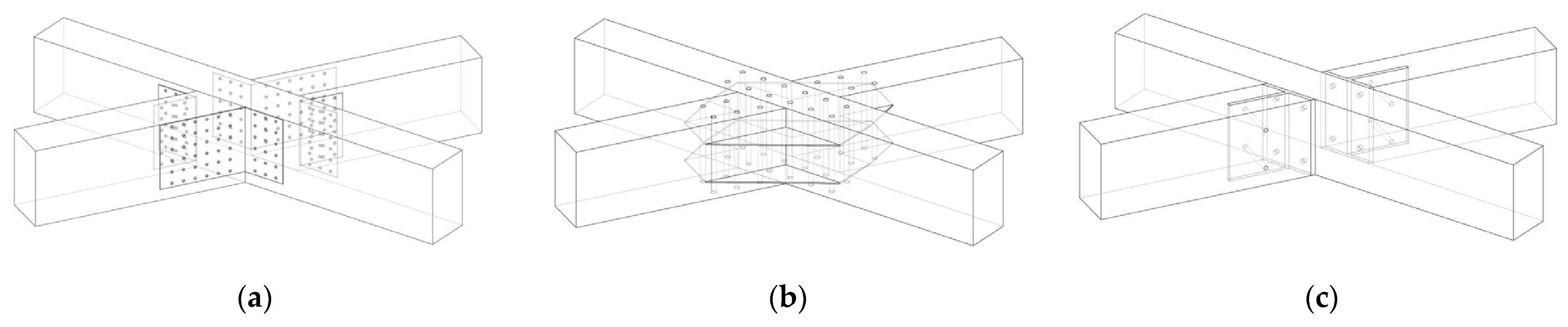
22] suggested that the axes of lamellae have to intersect in the joint, thus differing from the original joint in the Zollinger roof, where the lamellae are spaced apart. To understand the design of the joints, one must first observe the geometry of the structure and the shape of the lamellae. As presented by Tutsch [
6], the lamellae can follow a helix curve on a cylindrical surface (
Figure 2a) and have a torsional shape, can be modified to a discrete torsion (
Figure 2b), or be vertically placed in relation to the floor (
Figure 2c). A thorough analysis of the geometry of timber lamella vaults was presented by Petrović et al. [
13], with the conclusion that the lamellae must follow a helix curve to be uniform and to intersect at the node.
The research presented in this paper represents an improvement on the existing knowledge and sets a basis for further study. Each of the existing joints for a timber lamella structure was analyzed in this paper, based on five parameters: (1) the eccentricity, (2) load capacity with emphasis on inner forces, (3) the number of elements, (4) ease of assembly regarding the lamella structure, and (5) adaptability to the circular cylindrical surface. The first four parameters are typical for any timber joint. The fifth parameter is significant because of the lamella axes’ complex geometry, as Petrović et al. showed [
13]. The systematization of joints is followed by a discussion that shows the advantages and limitations of the presented joints, to give a conclusion about the best possible solution for a timber lamella joint, which will be applied to the prototype.
2. Geometry and Characteristics of Timber Lamellae
Lamella is a linear structural element, small in length compared to the span of the structure. The geometric configuration of lamellae is a diamond pattern. In the Zollinger roof, the lamellae are planks with a beveled upper edge. They are mounted by placing the end of one lamella on the middle of the lamella from the other direction. All the lamellae are vertical in relation to the floor, and their shape gives the roof the shape of a pointed arch made of two segments, with the geometry of a right circular cylinder (see
Figure 1). The lengths of the axes of the lamellae are equal, except for those on the perimeter of the structure, where the length of the axis of the lamellae is half the length of the axes of the other lamellae. The ends of the lamellae are shaped concerning their position in the structure: central lamellae, lamellae on the crown, and ridge lamellae.
The first lamella structure, the Zollinger roof, was formed by lamellae made of monolithic timber with a cross-section width of 2.5 cm or 5 cm, depending on the span of the roof and the length of the lamellae themselves [
23]. Three lamellae meet at the node—one central lamella and two connecting ones separated by three times the width of one lamella. When the cylinder is divided into equal segments, and straight lines connect the points on the cylinder envelope, the end of the lamella from one direction does not intersect with the middle of the lamella from the other direction [
13]. In the Zollinger roof, this problem is solved by shaping the upper edge of the lamella as an arch, achieving a higher cross-sectional height in the middle of the lamella at the point where the connection is made. The joint of the lamellae in the Zollinger roof is made with bolts.
A geometric analysis of a timber lamella vault [
13] represents one of the possible solutions for the design of the lamellae. Different sets of lamella axis lengths are obtained using the graphical method of projecting the grid onto the cylinder envelope. The lamellae remain vertical in relation to the floor, as in a Zollinger roof. The axes of the lamellae are planar arcs belonging to the envelope of the cylinder, and each lamella can be shaped as a glued laminated timber arc. This geometric model shows that the lengths of the lamella axes increase from the ridge to the crown, while at the same time, their angle of cut increases [
13]. The ridge lamellae are vertical and are placed parallel to the ground. The lamellae along the crown have a slope of 30–60°, depending on the segment of the cylinder envelope on which the grid is projected. The pitch of the lamella determines the angle of the end cuts, as well as the design of the lamella joints. In the example of the roof structure for an ice rink in Toronto [
24], a T-section steel plate connection is used for the joints, in which the shape of the steel plate follows the cut at the lamella ends.
Another graphical method, dividing the cylinder into equal segments, produces lamellae axes of the same length [
13]. This lamella type was adopted for designing the prototype, because it retains the advantages of the original lamella construction, the Zollinger roof. The ideal curve along that the lamellae is a spatial curve—a helix. The lamella roof should be designed so that axes of lamellae intersect at the node and create a continuous roof surface for installing the cover. A lamella structure with the axes of the lamellae as helixes produces lamellae that are all the same, but they are torqued around their longitudinal axes. The simplification of the spatial curve, the helix into a planar arc, contributes to the simpler execution of the lamellae, which remain uniform [
13]. For the prototype of the structure, lamellae with a cross-section of 6/16 cm were designed, which were made of glued laminated timber arches, the axes of which intersected at the node, as shown in
Figure 3.
Figure 4 shows one isolated planar arc lamella applied to the prototype of the lamella structure. The ends of the lamellae were cut at an angle, so that the cross-section pressed onto the central lamellae where the connection was made. The lamella joint must be designed to correspond to the rotation of lamellae in the node, which occurs because of the simplification of the axis of the lamellae. The differences in the types of lamella appear based on their position in the structure and length along the perimeter (half the length of the axes of the typical lamellae). The joints at the ends of the lamellae differ from the position where they connect with other structural elements.
3. Types of Joints for Timber Lamellae
Joints for timber structures can be classified into four major types: (1) wood joints; (2) joints with bolts, nails, or dowels; (3) joints with steel plates; and (4) joints with adhesive. The first type is usually used for carpentry and classical roofs. The second and third types are interchangeably used, depending on the structural loads of each joint in the structure, while joints with adhesive are still being researched [
15]. Joints for timber lamella structures have changed over the past century, from simple bolt joints to experimental ones using plates, bolts, and dowels.
3.1. The Zollinger Joint and Its Modification
Zollinger roofs were made as part of a circular cylinder surface. To place the lamellae vertically in relation to the floor, they have to be rotated to follow the path of the helix, as shown in
Figure 2c. The Zollinger roof was made of planks with variable cross-sections and processed in a workshop according to the template [
23]. Since the state of the art in the 1920s demanded a bolted connection [
12,
21], Zollinger needed to overcome two limitations: the helix shape of the curve, and the required spacing of the lamellae for mounting the bolts.
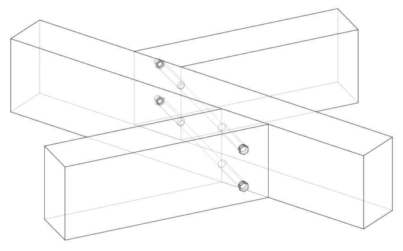
The original joint in the lamella structure is formed with bolts that pass through three lamellae, one is placed centrally, and the connecting lamellae are rotated and spaced apart by three lamella thicknesses, as can be seen in
Figure 5 [
25]. The spacing between lamellae is used for easy bolt placement [
21], while at the same time, it solves the problem of the geometry. All lamellae are vertical in relation to the floor, and this spacing allows them to follow the path of the helix from one support to the next, while remaining the same length [
6]. In the zone where the connecting lamella is obliquely pressing onto the central lamella, transverse forces and bending moments around the vertical axis occur. The normal force from the connecting lamella is transferred via a bolt, and bearing stresses appear around the borehole. However, the advantages of this connection are its easy assembly and the possibility of replacing the lamella if needed [
21]. The eccentricity in the joint creates a bending moment in the area where the cross-section is weakened. The author overcame this by employing a variable cross-section, reaching its total height in the weakening area. This variation is also used to create the curvature of the roof.
The design of the Zollinger’s joint was developed following the state of the art and the roof’s geometry. At the same time, the architect achieved ease of construction, uniform elements, and an aesthetically pleasing structure.
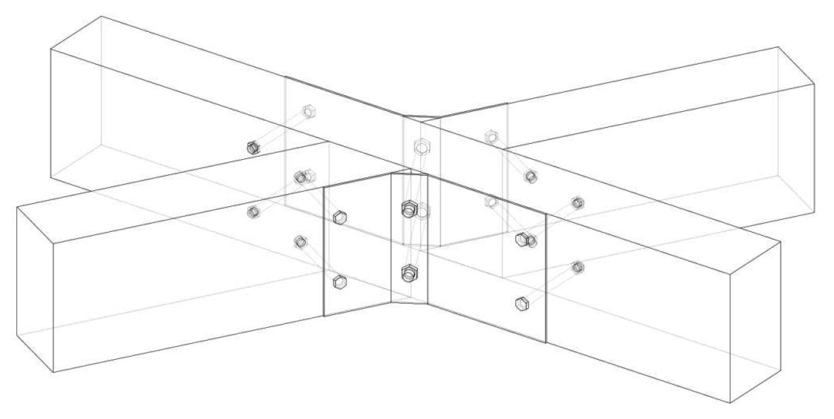
A modification of the original joint was presented in the book by Müller [
25]. The space between connecting lamellae is lost, and additional steel plates and bolts are placed to join the three lamellae in the node. This type of joint is not seen in other literature and is not explained in this book either. As presented in
Figure 6, it can be concluded that the axes of the lamellae intersect in the node and that there is no eccentricity, making this joint an improvement on Zollinger’s joint. On the other hand, the geometry of the lamella structure has to be changed for this node to be applied.
Figure 2a,b show a possible solution for the torsion of the lamellae needed to allow the axes to follow the helix curve on the circular cylinder surface. This type of joint would have to be modified for vaulted lamella structures.
3.2. Wood Joint for Lamellae
Recent research on lamella structures conducted by the FLEX team from the Hochschule für Technik, Wirtschaft und Kultur (HTWK) Leipzig led to the invention of a new wood joint called the micro-step joint (
Figure 7). The connecting lamellae are closer together, and the whole cross-sectional area transfers the forces, since there is no bolt. The eccentricity and the moment around the vertical lamella axis are reduced. Screws are used to tighten the joint, which are calculated using the transverse force that appears in the node. The cross-section in the middle of each lamella is weakened by the offset in the area where the tension from the bending moment appears [
21].
The Zollinger and the micro-step joint were subjected to testing of compressive strength. The micro-step joint proved more efficient in its loading capacity; 80% stronger than Zollinger’s joint. It also showed a more uniform distribution of forces. The typical failure behavior of the Zollinger joint is displayed in the zone of the bolted connection, where cracks appear along the fiber of the wood. The micro-step joint failed where the cross-section had been weakened, so the central lamella broke. Since the micro-step joint was made with connecting lamellae spaced apart, to allow a comparison with Zollinger’s joint, the conclusion was that it would be possible to make it more efficient by pulling the lamellae closer together, thus reducing the eccentricity and the bending moment and increasing the load carrying capacity [
21]. The micro-step joint can also be observed as a modification of the Zollinger joint, which was designed based on contemporary technical solutions. The lamellae can be shaped and sized on a CNC machine [
21], making production fast and easy. Another research work from the HTWK explored the assembly of the lamella structure, showing a method for manufacturing the lamella ends [
26].
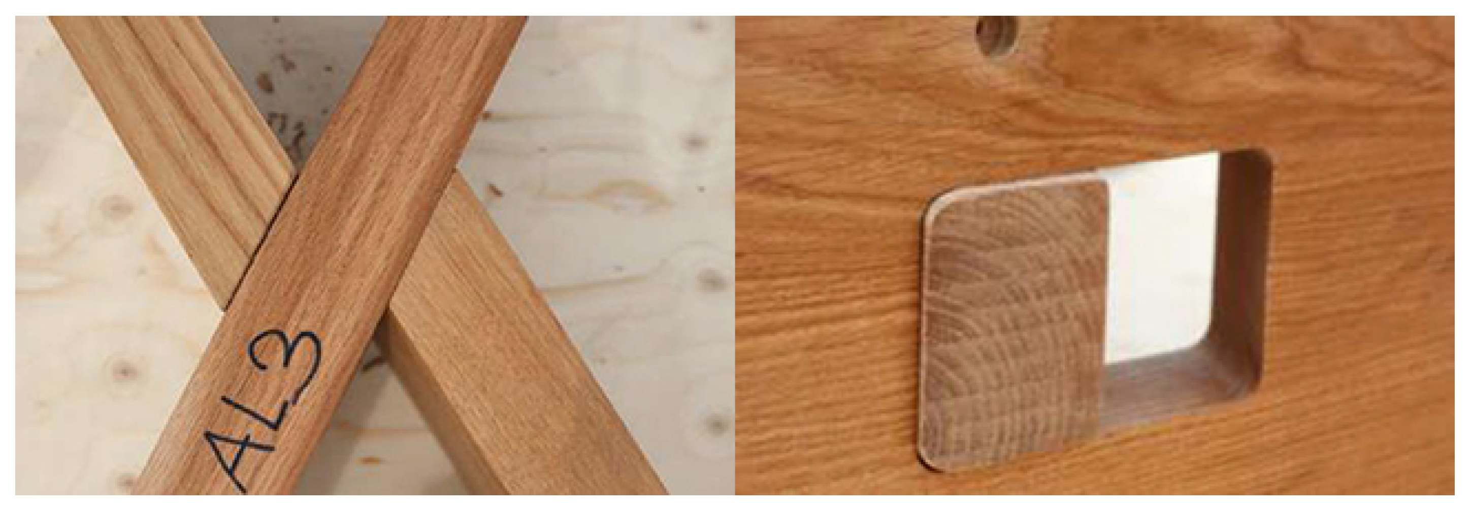
Another wood joint for the lamella structure can be seen in an example from Great Britain, constructed in 2019: a Wiltshire family home by Bath Bespoke. The diamond pattern was applied to a simple pitched roof, and the lamella joint was built without steel elements as a traditional mortise and tenon joint. The middle of each lamella was cut in a rectangular shape, to place the connecting lamellae through the opening, as shown in
Figure 8 [
27]. This type of joint is simple and efficient, but only for flat surfaces. The question remains if it could be applied to curved surfaces. The design authors emphasized that the joint needed to be precisely constructed, so the modules were built in a workshop and then transferred to the site to be assembled in place [
27]. There must not be any gap between the lamellae for this joint to work, because all forces are transferred along the perimeter of the mortise. This type of wood joint follows the contemporary aspiration for a green, no-carbon future, but they require further development to be used commercially. Experiments regarding carpentry joints are being carried out, to examine their bearing stiffness and to propose their use in contemporary structures [
28]. The presented joints are strengthened with screws/dowels, but to be sustainable, they should be designed as Japanese wood joints [
29].
3.3. Lamellae Joints with Steel Plates
The authors of the Timber Construction Manual propose three more types of joints for timber lamellae [
22]. In these joints, the axes of the lamellae intersect in the node, and the connection is achieved with steel plates nailed or bolted to the lamellae.
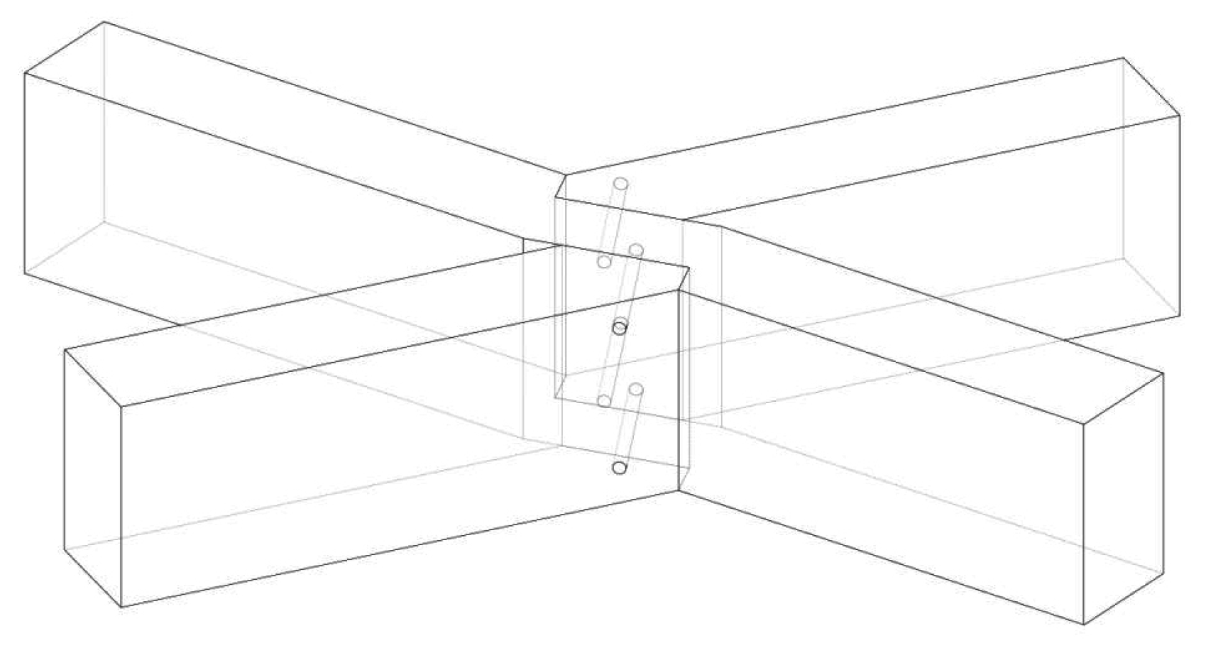
The first joint, the nailed bent steel plate joint shown in
Figure 9a, is similar to the modified Zollinger joint presented by Müller. It is constructed with bent steel plates nailed to the lamellae, following the angle at which they are placed. The timber and steel elements are separated. The steel plates can be prefabricated to the designed angle, and there is no need for additional shaping of the lamellae. However, nails cannot be placed if the angle is less than 90°, so an improvement of this joint is needed. As in the modification of Zollinger’s joint [
25], one possible solution is to only place the steel plates on the obtuse angles.
The second joint, the horizontal plate joint in
Figure 9b, is constructed of horizontal steel plates put into slits in the lamellae and nailed to them from the top. The advantage of this type of joint is having a moment connection between the lamellae. For a diamond pattern structure, a moment connection means the quadrangle is stiff and does not need additional elements, such as purlins or bracing.
Figure 9c shows the third joint presented in the manual, the T-section joint, which is primarily used in timber structures. This joint is constructed from two steel plates, which form a T-section, let into slits in the center of the lamellae and dowelled. The experimental tests for this type of joint showed that this is a semi-rigid connection, which should be analyzed as such [
30,
31]. This joint is easily adapted to any angle of the lamellae and is hidden inside the lamella, thus protecting the steel from corrosion. Compared to the last two joints, it does not affect the overall appearance of the timber lamella structure. The loading capacity of the T-section joint can be regulated by the thickness of the steel plate and the number of bolts. Joints with two steel plates have a greater overall loading capacity than the other joints presented. An experiment with axially loaded elements with dowelled joints confirmed their high load capacity and versatility of application [
32].
The choice of the right joint depends on the structural design, the necessary loading capacity, and the dominant forces in the nodes. The proposed joints with steel plates eliminate the eccentricity in the node but require a change in the geometry of the lamella structure. Compared to Zollinger’s joint, these joints are more complicated to manufacture and install, but perform better than a bolted connection. The second and third joints require additional shaping of the lamellae for placement of the steel plates. Thus, more time is needed for manufacturing.
3.4. The Joint by Scheer and Purnomo
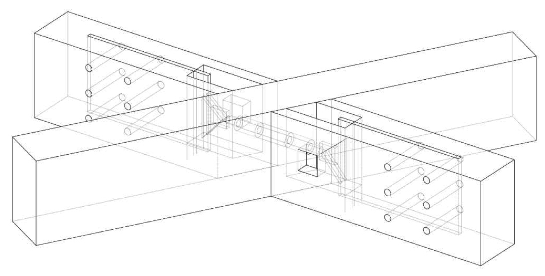
The engineers Scheer and Purnomo from the Technical University of Berlin researched timber lamella barrel vaults (lamellae on a circular cylinder surface). The results of numerical model and prototype testing led them to the conclusion that there is a need to develop a new joint according to the design regulations for timber structures. The authors proposed an adjustable and detachable joint, as shown in
Figure 10 [
33]. As a hinge-type joint, it requires additional elements in the lamella structure, such as purlins or roof decking. The ends of each lamella are shaped and cut to place a steel plate dowelled to the lamella. A tread bolt is attached to a triangular plate, to mount the lamella onto the center of the next one. An additional joint element is a screw spanner used to tighten the joint. The joint is constructed by mounting the connecting lamella with the tread bolt to the internal thread installed in the center of each lamella, which allows rotation around the longitudinal axis of the lamellae (torsional moment) in the connection.
The advantages of this proposed joint are the easy mounting of the lamellae, due to its adjustability and the possibility of detachment. The outside appearance of the joint does not affect the aesthetic of the timber lamella structures, because the only visible parts are the dowels, which can be hidden behind timber plugs. Its disadvantages are the complexity of the fabrication of elements and the joint installation, such as the cutting and shaping of the lamellae, which would take more time to manufacture than for the other joints previously presented.
4. Systematization of the Existing Joints for Timber Lamellae
The joints were analyzed based on the following parameters:
the eccentricity,
load capacity,
number of elements/complexity of the joint,
ease of manufacturing and assembly,
adaptability to the cylindrical surface,
Table 1 presents the existing joints, showing the floor plan and the axonometric view of each joint, the elements of the joints, the eccentricity, the moment transfer, advantages, and limitations. These parameters were chosen based on the description of the existing joints presented in the previous section. The eccentricity was singled out as one of the main problems of Zollinger’s joint, because it produces a bending moment around the vertical axis of the lamella, usually where the lamella’s cross-section is weakened. The load capacity of any joint is vital, so it is defined as the second parameter for analysis. The complexity of the joint is an essential parameter in the study of timber lamella joints, because the aim is to achieve an economical structure. Very complex joints raise the price of the production and/or assembly, which leads us to the fourth parameter for analysis. The last is focused on the geometric design of the timber lamella vaults. The design of the joint depends on the shape and position of each lamella in the structure, which is defined by its geometry [
6,
13].
Table 1 aims to systematize the existing joints, to draw conclusions about their modification and propose a new timber lamella joint. The eccentricity is observed based on the dominant axial forces acting on the lamellae. The moment of eccentricity appears around the vertical axis of the lamella. Analyzing the joints for timber lamella structures based on these parameters helps determine possible solutions for this structure when applied to a circular cylindrical surface.
Table 1 shows that the new joint has to be designed such that the lamellae axes intersect in the node, to eliminate eccentricity, as is presented in the advantages column for all joints except the Zollinger joint and the wood joints. The new joint should be a moment connection to stabilize the diamond pattern in the lamellae structure. The main connection elements should be placed inside the lamellae and dowelled or bolted to permit a concealed joint. The new joint should have a clear separation of elements and a simple prefabrication method.
5. Discussion on the Analyzed Timber Lamellae Joints
Most presented joints suppose that the axes of the lamellae intersect in the node, making this an essential parameter for comparison. The idea behind this solution is the elimination of the eccentricity that appeared in the original Zollinger joint. The axial forces dominate the lamella structure, creating a moment of eccentricity around the vertical axis for each joint where the connecting lamellae are spaced apart. The joint with the highest eccentricity is Zollinger’s joint. The wood joints are designed with the connected lamellae spaced apart, but the spacing is reduced to one width of the lamellae. The micro-step joint has proven to be more efficient than Zollinger’s joint regarding the load capacity, because of the reduced eccentricity [
21]. The eccentricity in the joint is eliminated by placing the connecting lamellae on one axis, as in all the other joints presented in this paper.
The contemporary joints presented in Timber Construction Manual [
22] have a greater loading capacity than the original one, because of the steel plates forming each joint. The joint with bent steel plates nailed to the lamellae cannot be manufactured as presented in the manual, since the nails cannot be installed at an acute angle. This joint needs improvement, but it should be considered one of the possible connections, since it can be easily adapted to a cylindrical surface, as opposed to the joint with horizontal steel plates. The horizontal plates would have to be parallel to the central lamella, so that they would be rotated about the connecting lamellae for the angle of their rotation, as in the concealed circular joint. The steel plate joint with the greatest loading capacity is the horizontal steel plate joint, which is a moment connection. The other two types of joint presented in the manual [
22] are semi-rigid [
30,
31]. The modification of the Zollinger joint presented by Müller [
24] and the T-section joint have a similar loading capacity, regarding the number of elements that form the joint.
When comparing and analyzing the existing timber lamellae joints, the conclusion is that Zollinger’s joint is the easiest to install. The wood and steel are separated, and the bolts used for the connection are standardized. The idea behind the joint design is for the workers to easily mount the elements, so that the roofs can be erected in a short period [
12]. On the other hand, the time for the preparation is less than for the other joints. The lamellae are cut and shaped in a workshop, but there is no need for the prior manufacturing of the connection elements. Other joints have to be previously manufactured in a workshop and transferred to the building site, which is the contemporary construction practice. The steel plates for the joints are cut, bent, and/or welded in a workshop and then nailed and bolted at the building site. The joint with horizontal steel plates and the T-section joint [
22] should be first installed in the middle of the lamellae, so that the steel plates dictate the position of the connecting lamellae, making the process of structure assembly simpler and faster. The Scheer and Purnomo joint is the most complex, since it has a large number of elements, and the preparation for the structure assembly is time-consuming. The lamellae need to be beveled, cut, and pierced, and the joint has to be prepared and assembled in the workshop, the steel plates cut and drilled, and the bolts installed. The wood joint applied for the classical pitched roof [
27] only has screws to reinforce the joint but is very complex to manufacture. The lamellae need to be precisely cut to form the connection, because there must not be any gaps between them. The preparation of the lamellae takes a lot of time and energy. The micro-step joint has several elements, similarly to the original one, but more time is needed to shape the lamellae [
21]. The precision of the cut can be achieved with the use of a CNC machine for the shaping of the lamellae, and this can also help reduce the production time.
Regarding the adaptability to a cylindrical surface, most of the proposed joints would have to be modified. The original joint was developed for a bolted connection, which required the lamellae to be spaced apart to place the bolts, thus producing eccentricity in the node but also solving the problem of the geometry of the lamellae axes following a cylindrical surface. The modification of this joint was guided by the idea of increasing the load capacity, while reducing the eccentricity. The lamellae were placed on the same axis, intersecting in the node, which resulted in rotation around their longitudinal axis, to follow the helix curve around the cylindrical surface. To have all the lamellae the same and for their axes to intersect, the ideal geometry of the axis is the helix, but then each lamella would have to be torqued. The helix must be simplified to an arch curve to manufacture the lamellae. The joint for a lamella structure applied to a cylindrical surface must follow the rotation of the lamellae, which requires a modification of the presented joints. The applied steel plates in the presented joints must be rotated, and the lamellae must be cut obliquely in the wood joints. The most straightforward modification is the rotation of the steel plates in the T-section joint [
22]. The plates are placed almost independently of the position of the lamellae from each other, so that they can follow the rotation of the vertical axis plane of each lamella. This rotation does not affect the joint’s design, since the plates’ position remains unchanged. The same goes for the Scheer and Purnomo [
33] joint design, since the steel plate is positioned in the connecting lamella’s vertical axis plane, and the central lamella’s threaded tube does not change its position in the joint. The problem with this joint is that the lamellae must be cut obliquely to the central lamella, making it more time-consuming, for an already complex joint. The production time could be reduced if the lamellae were shorter and cut only for installing the steel plate, while the triangular steel plate with screw spanner would not be concealed into the lamellae. The steel plates in the joint with horizontal steel plates [
22] pass simultaneously through all three lamellae, so they cannot be modified. The horizontal steel plate joint is complex to manufacture, because the slits for the horizontal plates need to be precisely cut for a specific angle of the rotation of the lamellae. For wood joints to be applied to a circular cylinder surface, the cutting and beveling of the lamella would be very complex and require great precision. The use of CNC machines could allow the manufacturing of lamellae for these joints.
6. Proposition of a Timber Lamellae Joint for a Prototype
The analysis and systematization of the joints showed that the joint design with steel plates is one of the most advantageous, as it has no eccentricity, no reduction of the lamella cross-section, and is easy to adapt and mount. Based on the geometry of the timber lamella structure, a joint has to be designed to follow the rotation of the lamellae in the node. The cylindrical surface requires a helix curve for the axis of the lamellae [
6,
13], so an idealization to the planar arc must be made. This results in the rotation of the lamellae, which appears in the node [
13]. The authors propose a joint with steel plates, inspired by the T-section joint and the bent steel plate joint [
22]. Even though the T-section joint was the authors’ first choice, because it is concealed inside the lamella and does not change the timber aesthetic, it has to be modified for the rotation in the node, elongating the plates and increasing the number of bolts. With this change, the most straightforward solution is to have the plates on the outside of the lamellae, reducing the time needed to produce and shape the lamellae. The designed joint is easily mounted onto the lamellae, and it decreases the time required for assembly, because it defines the exact position of the next lamella in the structure.
The designed joint is presented in
Figure 11 and was implemented for the prototype design of a timber lamella vault presented by Petrović et al. [
13]. The first steel plate of the joint is positioned in the center of the lamellae, while the other two plates follow the outer sides of the connecting lamellae and their rotation. The position of the bolt holes is defined using Eurocodes 3 and 5 [
34,
35].
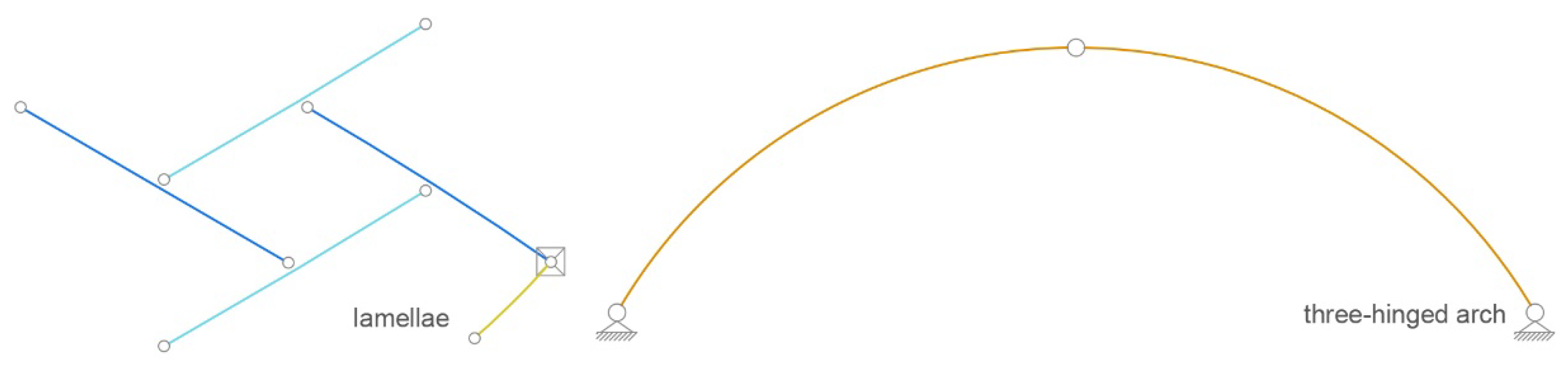
The prototype is a timber lamella vault following a cylindrical surface. It has a span of 10.75 m, and it was designed using arched lamellae lying on point supports and three-hinged arches as gable arches of the structure. All elements were made from glued laminated timber. A finite element model was designed for snow and wind loads on the structure [
36], to obtain the maximum forces for the designed timber lamella joint. The model of the lamella structure was made of arched beams—lamellae, connected with hinges, and with three-hinged arches at the gable ends (
Figure 12). The load capacity of the joint was calculated using Eurocode EN 1995-1-1:2012 [
35]. The joint was designed as a double-shear steel–wood connection with thin steel sheets, t = 3 mm, placed laterally to the wood and bolted with M12 bolts, class 5.6.
The characteristic load-carrying capacity per shear plane per fastener should be taken as the smallest value obtained from the following expressions, for thin steel plates as the outer members of a double shear connection, according to the failure modes for steel-to-timber connections J and K:
where
fh,α,k is the characteristic embedment strength in the timber member,
My,Rk is the characteristic yield moment of the fastener,
t is the plate thickness and,
d is the diameter of the fastener.
The characteristic embedment strength is calculated as follows:
where f
h,0,k is the characteristic embedment strength parallel to the wood fiber calculated as
Since the timber density for lamellae is ρ
k = 450 kg/m
3 and k
90 = 1.53, the angle between the resulting force and the grain direction is α = 5.83° according to the formula:
The value of the characteristic embedment strength parallel to the grain is fh,0,k = 32.295 N/mm2.
The characteristic yield moment of the fastener depends on the diameter of the fastener d = 12 mm and its characteristic tensile strength f
u,k = 560 N/mm
2 and is calculated as:
The value of the characteristic load-carrying capacity per shear plane per fastener for mode J is:
and for mode K is:
Making the value for mode K the minimum value. The axial force accepted by one bolt equals
and for a double-shear bolt, the axial force equals N = 25,832.5 N.
The calculation if the total load capacity in the grain direction is shown in
Table 2.
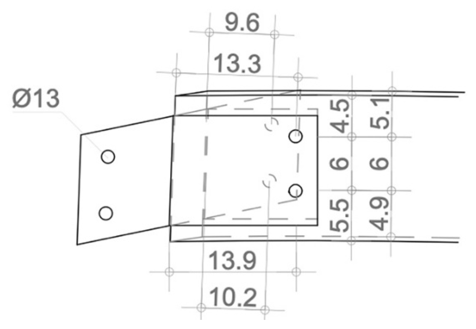
The dominant forces in the timber lamella vault are axial forces. The maximum resultant force in the joint from the finite element model was R = 17.59 kN, so it was concluded that the designed connection was suitable for the prototype. The dimensions of the steel plates and the position of the bolt holes are presented in
Figure 13.
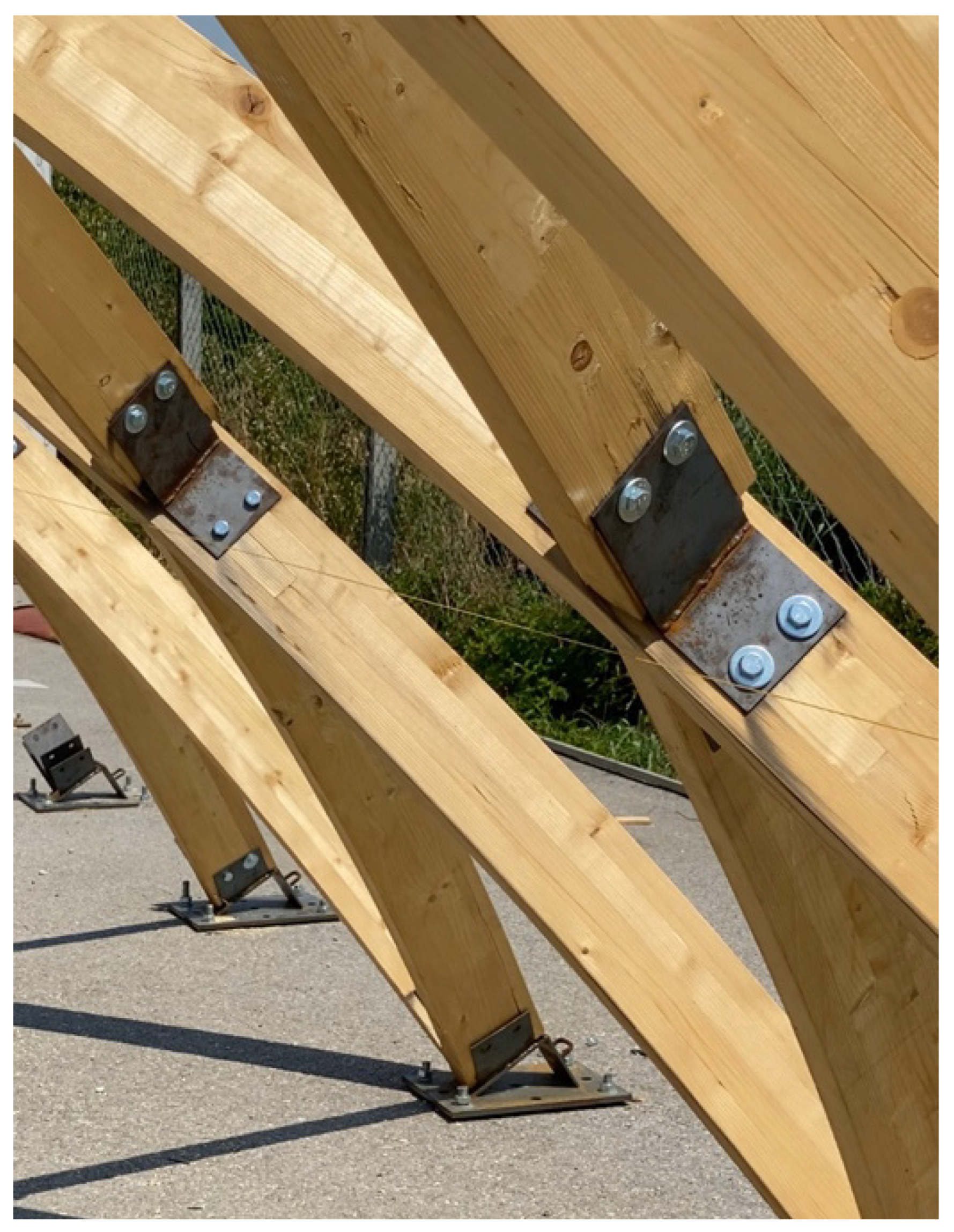
The designed joint was applied to the prototype of a timber lamella structure. During the assembly, the previous conclusions about lamella structures were analyzed. The advantages of historical lamella structures are the uniformity of the elements, the ease of assembly, and the economic structure. The chosen lamella and joint design for the prototype confirmed all these advantages. All lamella axes were the same length, except the ones on the perimeter, which were half the length. There were six types of lamellae and corresponding joints, because of the different cuts at the ends of the lamellae depending on their position in the structure, confirming that the timber lamella structure had uniform elements. The amount of time needed for shaping and mounting the lamellae was short, and the whole structure was built in less than a week, with only three workers [
13]. There was no need for scaffolding. In the beginning, simple supports had to be placed, but immediately after placing several lamellae, they could stand independently. Every additional lamella reinforced the previous one and set its position in the structure. The production of elements and the structure assembly confirmed the ease and economy of construction.
Figure 14 shows a prototype segment, where the joints can be seen.
7. Conclusions
The presented research demonstrated a timber lamella vault and an analysis of its elements. The redesign of a timber lamella vault according to the authors’ preferences and contemporary design guides required a new lamella and joint design. The idea behind the design was to keep all the advantages of the historical lamella structures: the uniformity of elements, the ease of assembly, and an economic structure. The presented design of an arched lamella and a steel plate joint, applied to the structure prototype, confirmed all these advantages.
The vital part of this paper was the presentation of the characteristics of the various joints for timber lamella structures. All joints were discussed, classified, and evaluated concerning the possibility of application for a cylindrical surface, since most lamella structures are built as vaults. The existing joints were systematized, and a proposition for a new joint was presented. The analysis led to the conclusion that each joint was designed according to the state of the art of the time and had its advantages concerning the analyzed parameters.
The overall conclusion was that the design of a timber lamella joint is complex and requires extensive geometrical and static analysis of the structure. The diamond pattern requires moment connection or purlins to achieve stability, so the joint has to comply with the structural design.
This research has confirmed the need to create prototypes in the modern age on a scale of 1:1, in which design problems and new or modified structural assemblies can be seen, as well as issues that arise when constructing the structure and preparing the workshop documentation.
Designing a timber lamella structure, which consists of many uniform elements (the lamellae and joints), opens the possibility of serial production. The lamellae’s small dimensions simplify the transportation and assembly process. The consumption of material per square meter of a lamella structure is approximately equal to the consumption of material for typical halls with a cylinder geometry of the same volume. However, the advantage of the lamella structure is reflected in the aesthetics of the diagonal network of timber lamellae.


