Article

Performance Analysis of Short-Span Simply Supported Bridges for Heavy-Haul Railways with A Novel Prefabricated Strengthening Structure

1
Key Laboratory of Railway Industry of Infrastructure Safety and Emergency Response, Shijiazhuang Tiedao University, Shijiazhuang 050043, China
2
School of Safety Engineering and Emergency Management, Shijiazhuang Tiedao University, Shijiazhuang 050043, China
3
School of Civil Engineering, Shijiazhuang Tiedao University, Shijiazhuang 050043, China
*
Authors to whom correspondence should be addressed.
Buildings 2023, 13(4), 876; https://doi.org/10.3390/buildings13040876
Submission received: 22 February 2023 / Revised: 24 March 2023 / Accepted: 26 March 2023 / Published: 27 March 2023
(This article belongs to the Special Issue Study on Concrete Structures)

Abstract

:
A novel prefabricated strengthening structure (NPSS) is proposed to improve the vertical stiffness and load-bearing capacity of existing short-span bridges for heavier axle-load trains passing through. The strengthening principle of the NPSS is revealed through theoretical derivation. A refined calculation model is prepared to investigate the effects of two important parameters on the structural behavior of the bridge, including the support stiffness and the installation location of the NPSS. The calculation model is also verified with four-point bending test of a bridge removed from a heavy-haul railway. With the calculation model and the response surface methodology (RSM), the functional relationships among the crucial mechanical indexes of the bridge and the two parameters of the NPSS are methodically established. Thus, the optimal values of the parameters are determined via a multi-objective optimization model and the analysis hierarchy process-fuzzy comprehensive evaluation method. Furthermore, the feasibility of the optimal parameters is appropriately verified based on simulations of the vehicle–track–bridge dynamics. The existence of the NPSS with optimal parameters could enhance the vertical stiffness of the bridge by 21.0% and bearing capacity by 19.5%. In addition, it could reduce the midspan dynamic deflection amplitude by 23.4% and vertical vibration acceleration amplitude of the bridge by 25.2%. The results of the study are expected to contribute to the capacity development and rehabilitation of existing heavy-haul railways with low cost and convenient construction without railway outage.

1. Introduction

As the main passage for transporting bulk goods, such as coal and ore, the heavy-haul railway plays a pivotal role in national economic construction and has become one of the crucial directions of the world’s railway development [1]. Heavy axle-load, long-marshaling trains, and high traffic density are the ways to improve transport capacity, and increasing axle load is the most effective measure to reduce costs and improve efficiency [2]. The mechanical performance of existing short-span simply supported bridges for heavy-haul railways is most sensitive to axle load. Therefore, the increase in axle load causes high deflection and crack propagation, which reduces the vertical stiffness and the load-bearing capacity of bridges [3,4]. It also seriously threatens the traffic safety of heavy axle-load trains [5,6,7]. Meanwhile, the service life of the existing short-span bridges with enormous stock is far from the design value. Considering the economic factor, the existing bridges cannot be demolished or reconstructed. Therefore, bridge-strengthening technologies are an effective way to improve the performance of the existing short-span bridges to realize the capacity development and rehabilitation of existing heavy-haul railways.
Numerous investigators have examined strengthening theories, experimental methods, materials research and case studies [8,9,10,11,12,13,14,15,16]. So far, many structure-strengthening approaches have been presented, and can be generally divided into three types, including the section augmentation type, external bonded materials type, and structural system transformation type [17,18,19]. Some of the methods are also used to improve the seismic performance of the existing structures, and many scholars have carried out substantial research for that reason [19,20,21,22]. When the section augmentation method is applied to bridges, it has significant impact on the original structure, train operation and traffic under the bridge [22,23,24,25]. Meanwhile, the strengthening effect of the method is suboptimal because of the small change in section size. According to whether prestressing is provided or not, the second type can be further divided into two subtypes, i.e., external non-prestressing method [26,27], and external prestressing method [9,10,28,29]. The bonded materials are mainly steel plates and fiber-reinforced polymer (FRP). Due to its high strength, light weight, noncorrosive nature and good fatigue resistance, the structure-strengthening method with FRP is one of the hottest globe research aspects in the field of structural maintenance [30,31,32]. Long-term application practice shows that the prestress loss of FRP is relatively large under long-term heavy axle load, which weakens the strengthening effect. In addition, brittle debonding failures and inapplicability on moist surfaces or at low temperatures are also issues that limit the full utilization of this method [9]. Due to its wide adaptability to small-span and long-span bridges, the third type is applied in more and more bridges. Zhou et al. [33], Xu et al. [34], Hu et al. [35] proposed transforming simply supported bridges into continuous systems to improve the transverse stiffness and reduce the deflection of double-T railway bridges or box-girder highway bridges. Song et al. [36] transformed rigid frame-continuous girder into a pseudo-cable-stayed system for mitigating the midspan deflection of the Yellow River Dongming Highway Bridge. Zhang et al. [37] also proposed changing long-span continuous box-girder bridges into self-anchored suspension bridges for controlling both the internal force and deflection of the main girder. Chen et al. [38], Hou et al. [39], and Jiang et al. [40] used external sub-structures to form a new system with the original structure which could substantially upgrade the mechanical behaviors of strengthened bridges. The third type of structure-strengthening approaches offers many desirable properties including high reliability, good fatigue resistance and high environmental adaptability, but the construction period with railway outage is too long to meet the requirement of high traffic density for existing heavy-haul railways.
Thus, a novel prefabricated strengthening structure (NPSS) for short-span simply supported bridges is proposed. The NPSS is constructed to change the support system of bridges by employing an assembly method which has no effect on train operation. Theoretical derivations and finite element simulation are employed to examine the effectiveness of the NPSS. Based on the response surface methodology (RSM) and the multi-objective optimization method, the parameters associated with the NPSS are optimized. Further, the effect of the optimized NPSS on coupled systems, including vehicles, tracks, and bridges, is also investigated on the basis of an inclusive dynamic analysis. The goal of the paper is to determine the key parameters of the NPSS and obtain the optimal values, which can provide guidance for the detailed design of the NPSS. Therefore, the detailed design method of the NPSS is not covered in this paper.

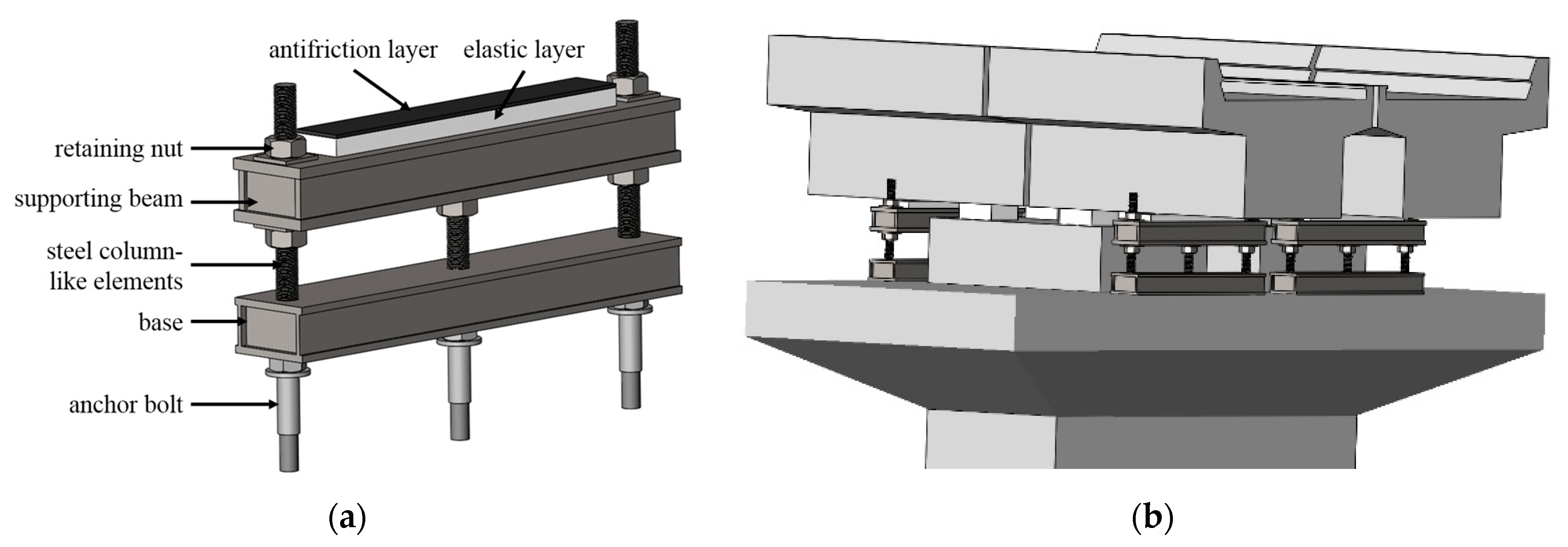
2. Proposed Methodology

In order to adapt to the limited installation space and lessen the installation effect on the operation of heavy axle-load trains, an NPSS is proposed for short-span bridges with simply supported ends, as demonstrated in Figure 1.
The NPSS is essentially composed of a base, steel column-like elements, a supporting beam, and an elastic layer. The base is connected to the pier top by the anchor bolts (see Figure 1a). The steel column-like elements represent an important device that connects the base to the upper supporting beam. The height of the supporting beam could be promptly adjusted with the bolts installed on the steel column-like elements. The elastic layer mounted on the supporting beam could provide an elastically appropriate support for the upper beam. The antifriction layer still should be installed between the elastic layer and the upper beam to lessen the influence of the NPSS on the longitudinal and transverse mechanical performance of the bridge. Since original bridge bearings undergo the dead loads of both the beam and the upper track structure, the NPSS only provides a proper support for the live load of trains. As the structures and sizes of short-span bridges which should be strengthened are dissimilar, the dimensions of the NPSS components should be designed for each bridge. The vertical stiffness and the installation location of the NPSS are the vital factors determining the produced stresses within the NPSS. Additionally, the produced stresses affect the design size of the NPSS, so the two factors denote the main analysis factors.

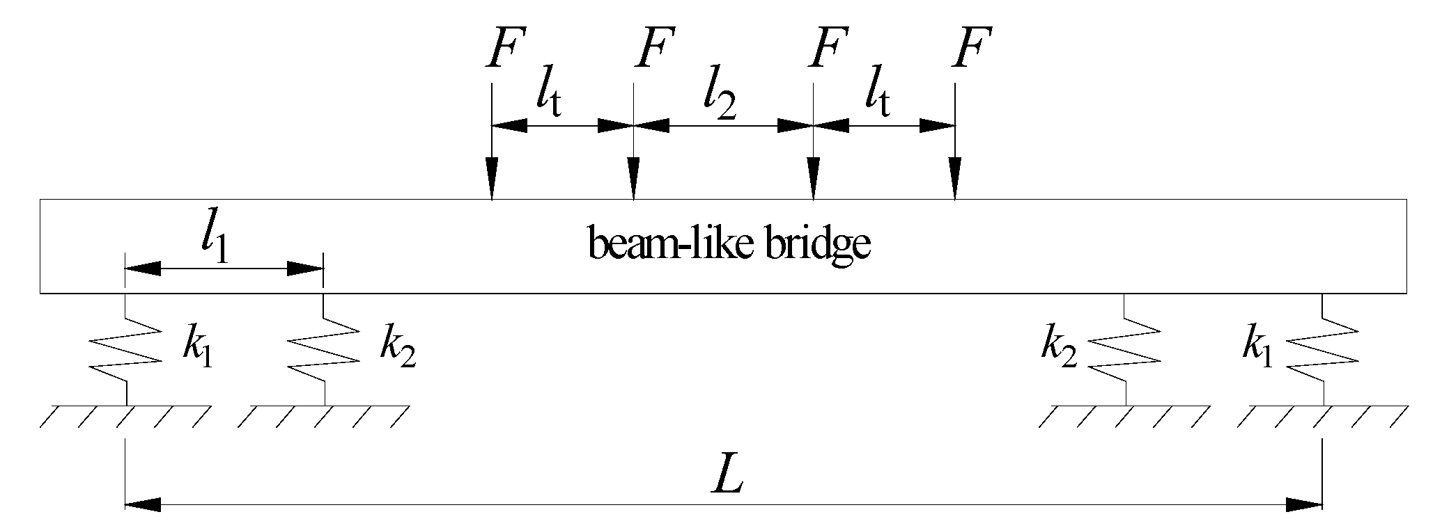
3. Theoretical Model

Based on the load bearing and force transmission paths of the bridge with attached NPSS, the whole system can be simplified into the mechanical model demonstrated in Figure 2. In addition, several simplification hypothesis or assumptions are taken.
(1) The three assumptions including continuity assumption, uniformity assumption and isotropy assumption in mechanics of materials are applied.
(2) The load diffusion caused by rail, fastener, sleeper and ballast bed is ignored.
(3) The support forces of bearing and NPSS are simplified as concentrated loads.
(4) The effect of shear on deformation is ignored.
An appropriate simplified mechanical model can be utilized to show the structural strengthening principle of the NPSS in view of the static performance of the bridge. For short-span bridges, the most unfavorable load condition is that the back bogie of the first vehicle and the front bogie of the second vehicle are symmetrically arranged in the midspan.
Without considering the influence of the shear effect, the midspan bending moment (M) and the deflection (w) caused by the load accounting for the NPSS are expressed by:
M = L l t l 2 B A l 1 F ,
w = C + B A D F E I ,
in which
A = 12 E I k 1 + k 2 k 1 k 2 l 1 + 6 L l 1 8 l 1 2 B = 24 E I k 1 l 1 + 3 L 2 l 2 2 6 l t l t + l 2 4 l 1 2 C = L 4 l 1 2 L 2 24 + E I 2 l 1 L k 1 l 1 + 2 l t + l 2 3 + l 2 3 48 D = E I L k 1 + k 2 2 k 1 k 2 l 1 E I k 1 + l 1 3 6 + L 2 l 1 8 L l 1 2 3
where EI denotes the vertical bending rigidity of the bridge, L is the computed span of the bridge, as shown in Figure 2, l1 represents the center distance between the bridge bearing and its adjacent NPSS, the factors lt and F stand for the bogie’s wheelbase and the axle load, respectively. l2 is the difference between lz and lt (see Figure 2), and lz denotes the center distance between the back bogie of the first vehicle and the front bogie of the second vehicle. F denotes the wheel weight. Furthermore, the factors k1 and k2 in order are the vertical stiffness values of the bridge bearing and the NPSS (i.e., bearing stiffness and support stiffness for short, respectively). Please see Appendix A for formula derivation.
For large values of the support stiffness, the support force of the bridge bearing and the NPSS subjected to the live load are in opposite directions. Additionally, it causes the NPSS to undergo a large vertical load, which is unfavorable for structural design. Therefore, the support stiffness should guarantee that the support force of the bridge bearing and the resulting force within the NPSS would be in the same direction, namely:
k 2 8 E I l 1 L 2 l 2 2 2 l t l t + l 2 + 4 l 1 l 1 L ,
Before strengthening, the midspan bending moment (My) is evaluated by:
M y = L l t l 2 F ,
Hence, the reduction of the maximum midspan bending moment (dM) caused by the NPSS is obtained as:
d M y = B A l 1 F ,
The presented relations above denote the main strengthening principle of the NPSS.

4. Finite Element Model and Verification

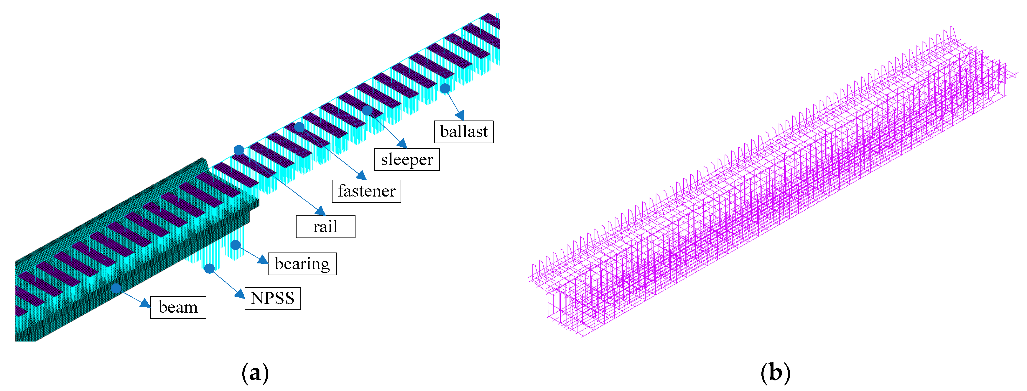
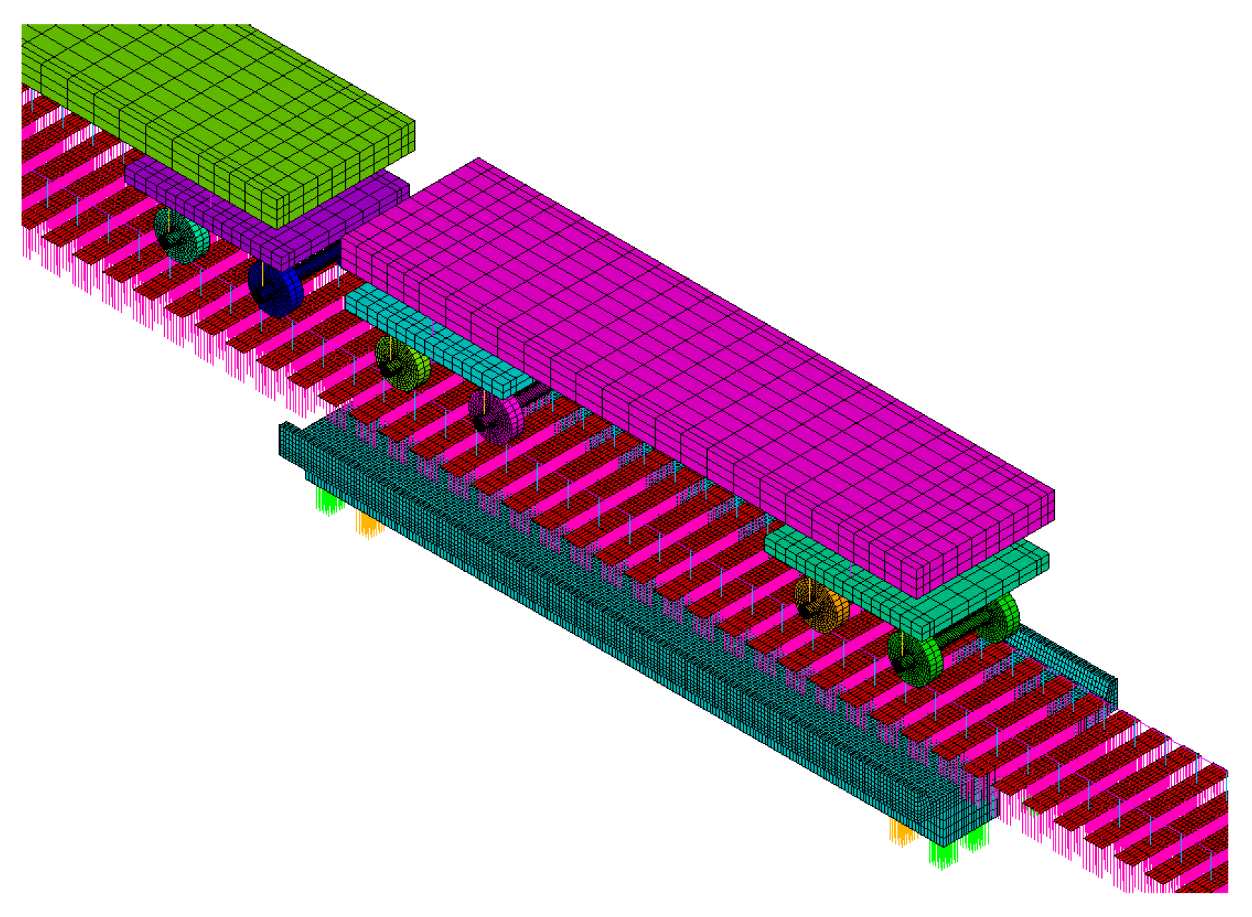
4.1. Finite Element Model
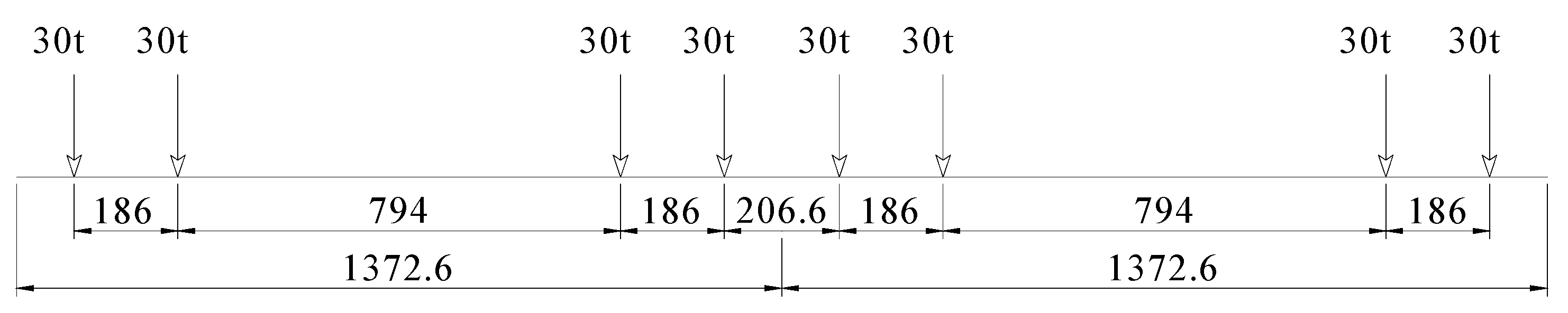
The theoretical derivation with the simplified mechanical model fails to consider the influence of some factors such as the track structure, the steel bars in the beam, and the nonlinear characteristics of material and support stiffness. Based on the discrete separated reinforced concrete modeling method, a refined calculation model considering the influence of various factors is established. In view of the symmetry of the structure, only half of the structure is adopted for modeling (see Figure 3).
Different components in the refined calculation model are simulated with various types of elements according to their mechanical characteristics. The rail is simulated by implementing the Timoshenko beam element, and the torsional freedom is constrained. The sleepers are simulated with shell elements to consider the force dispersion effect. The concrete of the beam is simulated with solid elements, and the stressed and structural steel bars in the beam are simulated by employing the link elements. The connection between the steel bars and the concrete of the beam is appropriately simplified as nodal links. The longitudinal resistance of fasteners, as well as the longitudinal and lateral resistance of ballast bed, could have substantial nonlinear characteristics, so nonlinear spring elements are employed to simulate them. This implies that the NPSS only undergoes pressure force but not tensile force; hence, a nonlinear spring element is also utilized for more rational simulation [41]. The lateral resistance of fasteners, vertical stiffness of fastener, and ballast bed and bridge bearings are simulated with linear spring elements. The nodes connecting the foundation and attaching to the spring elements simulating the bridge bearings, the NPSS and the ballast bed outside the bridge are constrained, which are the boundary conditions of the model. The number of nodes and elements is 220,257 and 269,063, respectively. Table 1 shows statistical information of different elements.

4.2. Experiments

In order to verify the feasibility and accuracy of the refined calculation model, a low-height reinforced concrete beam with simply supported ends and a span of 12.5 m is taken as an example. The beam was removed from an existing heavy-haul railway in China, and it has served for more than 20 years. It is a reinforced concrete beam. The cross-section size of the beam is shown in Figure 4. Based on the design data, the concrete of the beam is C30 concrete. The standard values of axial compressive strength and axial tensile strength are 20.1 MPa and 2.01 MPa, respectively. The elastic modulus of the concrete is 3.0 × 10⁴ MPa. Figure 5 shows the detailing of steel bars.
Two kinds of steel bars are used in the beam, including hot rolled plain steel bars (HPB) and hot rolled ribbed steel bars (HRB). The yield strengths of the two kinds of steel bars are 300 MPa and 400 MPa, respectively. The steel bars with yield strength of 300 MPa are mainly used as structural reinforcement bars. The diameters of steel bars range from 8 mm to 25 mm. In Figure 6, the principle of the four-point bending test is demonstrated.
During the test, four synchronous jacks provide the applied load, and the pressure sensors located between the reaction frame and jacks are also utilized to precisely measure the load. Meanwhile, the displacement sensors located at the cross-section of bearings and midspan are implemented to measure the deflection of various sections of the beam. The detailing of sensors is shown in Figure 6. The parameters of sensors used in the test are shown in Table 2. Figure 7 shows the field test.
Before the start of the test, preloading is carried out to eliminate the gap between the test beam and equipment. The grading loading method is adopted, and the load increment of each stage is about 10 percent of the estimated ultimate bearing capacity. Each level of load is held for 5 min, and then the test data of sensors is recorded.

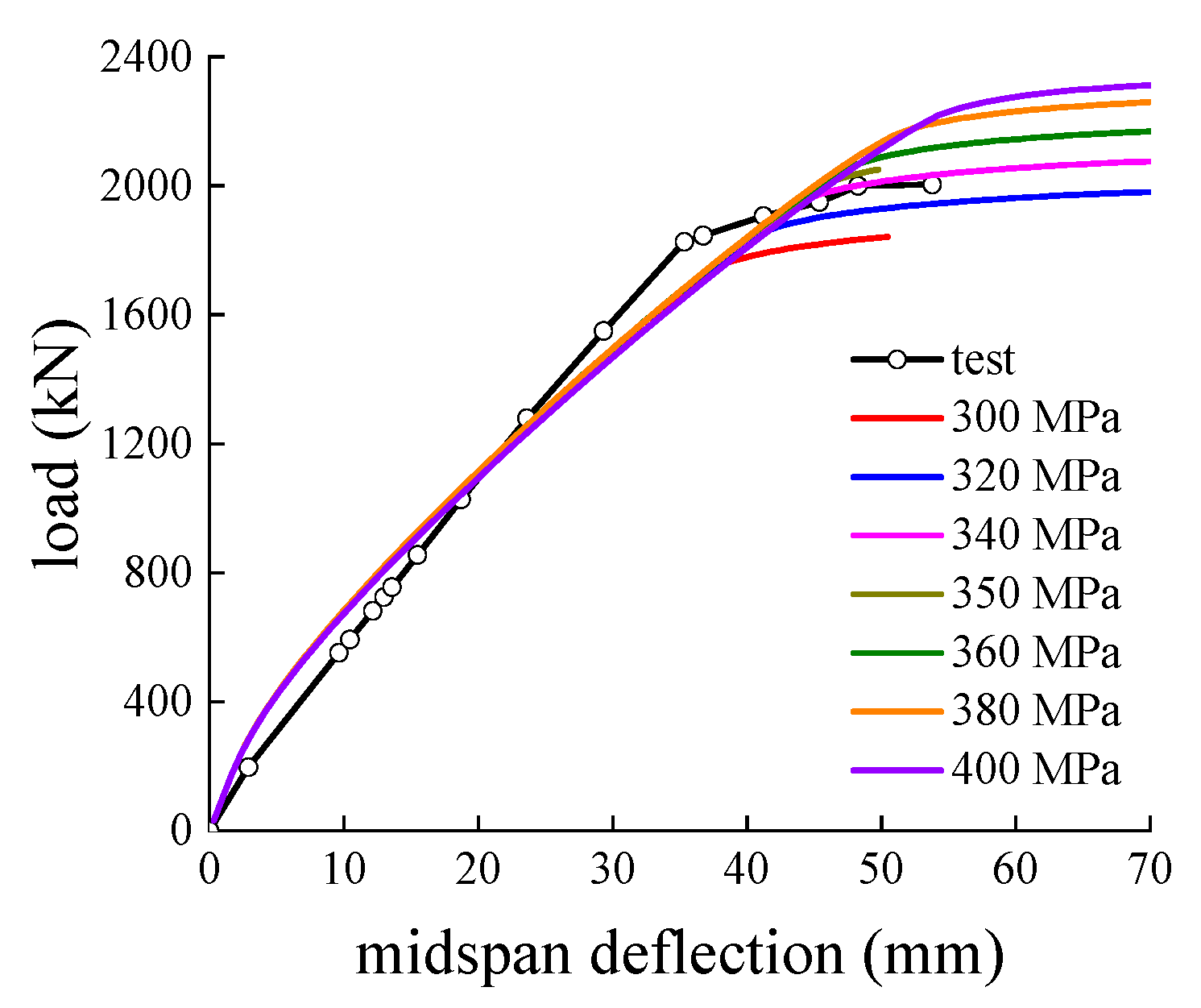
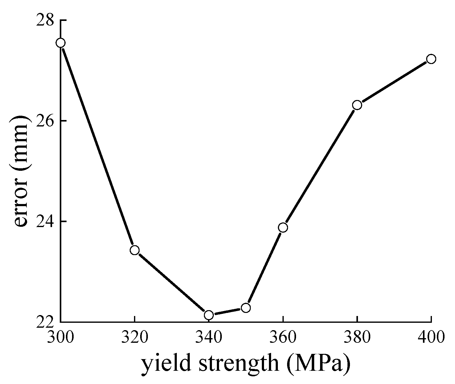
4.3. Comparison between Model and Experimental Data

Through combining the design parameters of the bridge and the experimentally reported data on material properties, the calculation parameters of the model are summarized in Table 3.
The plastic characteristics of the concrete and the steel reinforcement of the beam are appropriately taken into account in the structural modeling. The relationships between the stress and strain of concrete under the action of uniaxial loads are illustrated in Figure 8a,b. The Drucker–Prager criterion is employed to model the yielding mechanism of the concrete.
Figure 9 illustrates the midspan displacement-load curves obtained by the test and the refined model. In order to remain consistent with the test state, the influence of the track structure on the bridge has been ignored in the calculation.
As can be seen from Figure 9, the change rule and the variation trend of the deflection-load curves of both the test and the calculation model are matched, which indicates that the calculation model could be employed for analyzing the interactions between the bridge and the corresponding upper track structure. There exists only a discrepancy at the yield position, essentially resulting from three types of errors. Firstly, the properties of materials at various locations of the test beam are not the same. Secondly, the nonlinear trend of the stress-strain curve and the failure criteria of materials employed in the calculation model still demonstrate an apparent distinction from the actual. Thirdly, the measure error is objective and unavoidable. The effect of yield strength of the steel bars on the inelastic response is most pronounced. Figure 9 shows the deflection-load curves with different yield strengths of the steel bars. In order to determine the appropriate yield strength, Formula (6) is introduced to get the error (Δ) between calculation and test results.
Δ = i = 1 n F C i F T i 2 n ,
where FCi, FTi stand for the i-th calculation and test data with the same deflection. n denotes the number of comparison data. Figure 10 shows the relation between the error and yield strength of the steel bars.
According to the results in Figure 10, the error is smallest when the yield strength is near 340 MPa which is close to the standard value of tensile strength of steel bars. Therefore, this value is used in subsequent analyzes. Considering the failure mode of the test beam and sufficient shear capacity based on the allowable stress method, the existing short-span simply supported bridges will not experience oblique section failure. Thus, shear strengthening measures are not covered in this paper.

5. Discussion

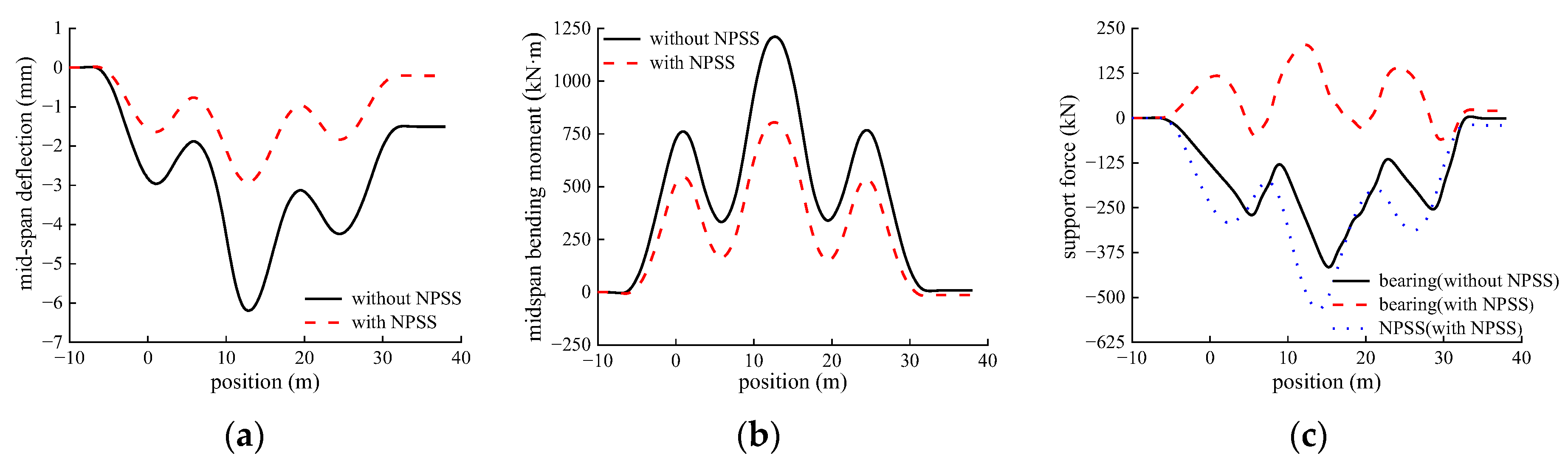
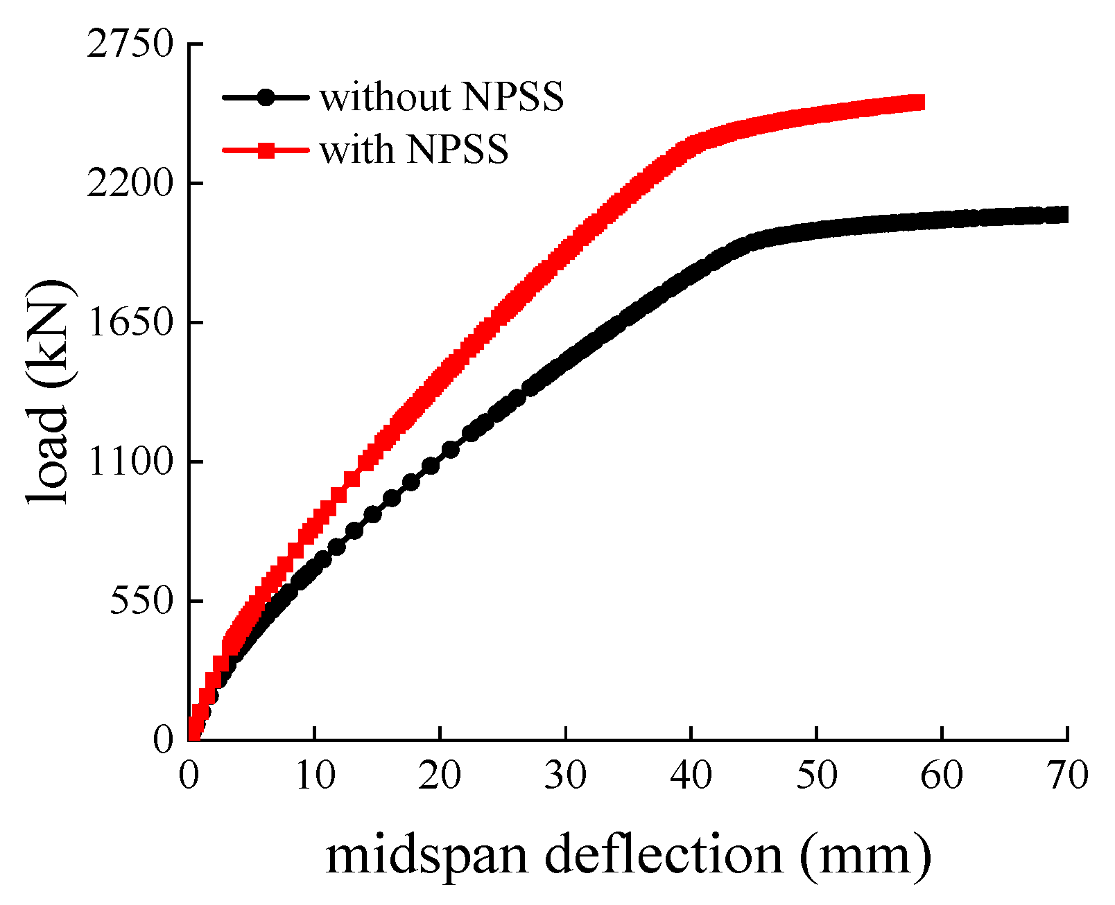
5.1. Comparison Studies with and without NPSS

A C96 vehicle with an axle load of 30 t is chosen as the loading system. The train loads and the corresponding parameters are illustrated in Figure 11 with more detail. In the calculations, two vehicles pass through the beam regardless of the dynamic effect that simulates various positions of the load relative to the base beam. The value of l1 is set equal to 0.8 m, and support stiffness k2 is set as 0.5 times of the bearing stiffness (k1) which is 2.46 × 10⁹ N/m. The calculation parameters of the track structure are also achievable in Refs. [42,43].
Figure 11 demonstrates the comparison results of the mechanical performance with and without NPSS. Figure 12a–c represents the midspan deflection, midspan bending moment, and the support force of the bridge bearing and the NPSS, respectively. The abscissa axis of Figure 11 represents the position of the first wheel, and the midspan of the bridge is zero.
According to the plotted results in Figure 12, the midspan deflection and bending moment in the case of using the NPSS are substantially reduced compared to the case without using NPSS. In the cases of with and without NPSS, the maximum midspan deflections in order are 2.9 mm and 6.2 mm, and the associated maximum bending moments are 804.8 kN·m and 1210.8 kN·m, respectively. These results clearly illustrate that the use of the NPSS leads to the reduction of the maximum deflection and bending moments of the midspan by 53.2% and 33.5%, respectively. As shown in Figure 13, the plastic deformation occurs without NPSS, resulting in an irrecoverable midspan deflection of 1.5 mm after the train leaves the bridge. In the case of applying the NPSS, the strengthening beam is mostly in the elastic state due to the decreased bending moment. This is also one of the reasons why the existing bridges should be strengthened during travel of heavy-haul trains. The directions of the support force of the bridge bearing with and without NPSS are dissimilar. The amplitude of the support force of the NPSS reveals an increase of 116.6 kN (i.e., 28.0%) compared with that of the bridge bearing without NPSS.
In order to make the support forces of the bridge bearing and NPSS in the same direction when the bridge is subjected to the live load, the ratio k2/k1 should be less than 0.15 by virtue of Equation (3). The excessive support force of the NPSS not only intensifies the difficulty in the structural design and the possibility of pier concrete collapse, but also leads to partial function loss of the bridge bearing. Therefore, it is necessary to optimize the support stiffness to ensure that the NPSS does not undergo too much load while improving the bridge stiffness and bearing capacity.

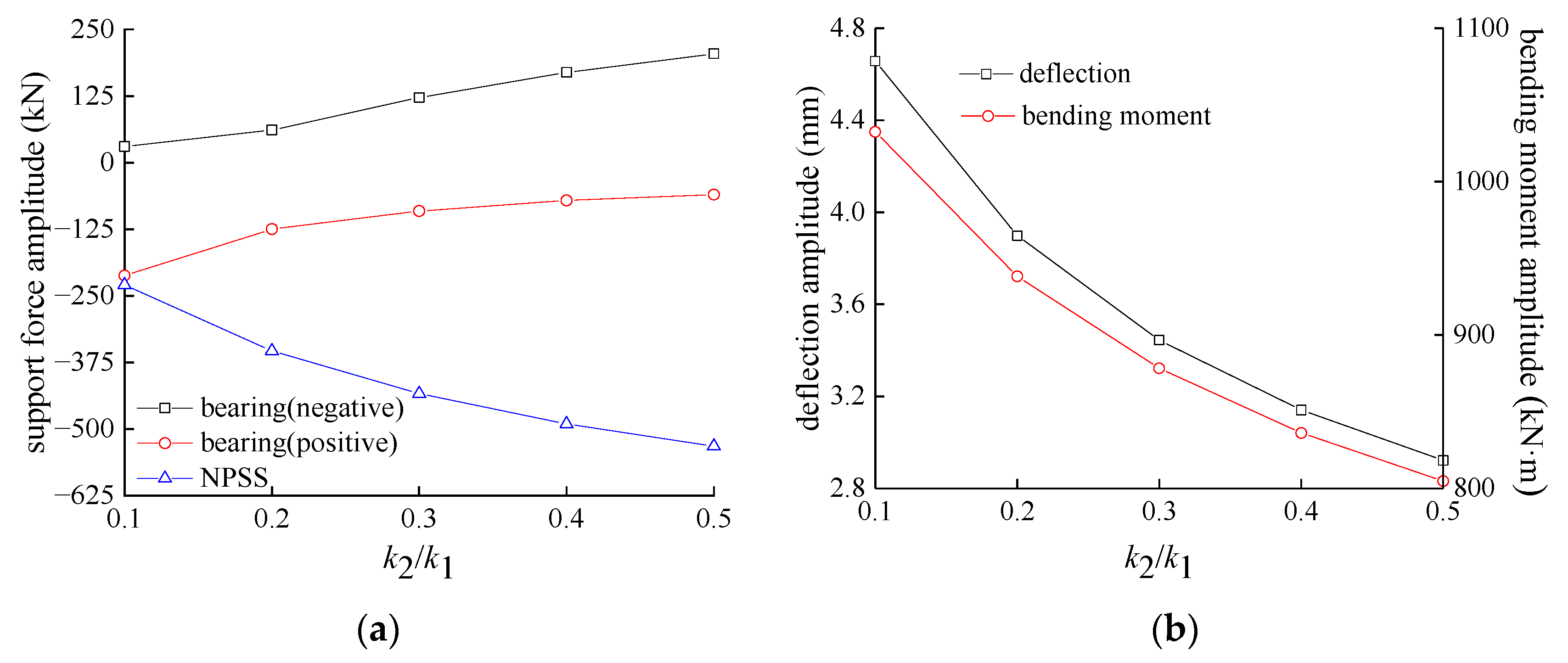
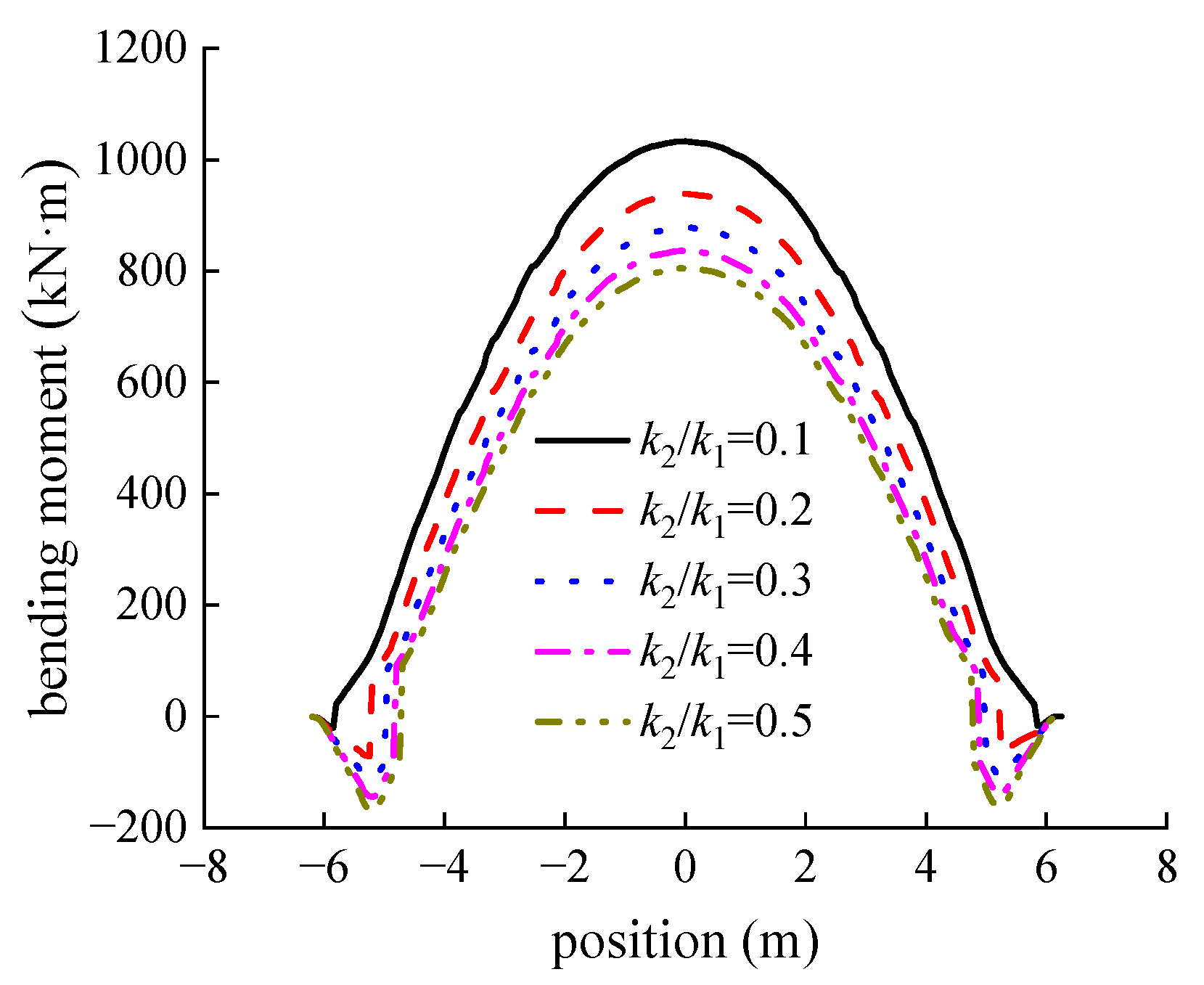
5.2. Influence of the Support Stiffness

In the current investigation, the values of l1 and k1 in order are kept fixed at 0.8 m and 2.46 × 10⁹ N/m, and five levels are taken for the ratio k2/k1 (i.e., 0.1, 0.2, 0.3, 0.4, and 0.5). The results by the calculation model are illustrated in Figure 14. Figure 14a displays the support force amplitudes of both the bridge bearing and the NPSS as a function of the ratio k2/k1. The support pressure force of the bridge bearing is viewed as positive, otherwise negative. Figure 14b is the relational curve between the midspan bending moment and deflection amplitude and k2/k1.
According to Figure 14a, with the rise of the support stiffness, the support force amplitude of the NPSS and the negative support force amplitude of the bridge bearing grow, while the positive support force amplitude of the bridge bearing lessens. For the ratio k2/k1 in the range of 0.1–0.5, the support force amplitude of the NPSS increases by 302.9 kN, indicating a growth of 132.0%. For the case of k2/k1 = 0.1, the support force amplitude of the NPSS and the positive support force amplitude of the bridge bearing in order are 229.5 kN and 212.1 kN. These values are approximately equal, representing that the NPSS and the bridge bearing collaboratively undergo the train load. Additionally, the negative support force amplitude of the bridge bearing is only 30.1 kN, revealing that the whole structure is in good stress performance.
According to Figure 14b, both the midspan deflection and bending moment amplitudes would lessen with the growth of the support stiffness; however, the reduction rate gradually reduces. On the one hand, the increase of the support stiffness leads to enhancement of the beam’s vertical stiffness. On the other hand, it provides a higher support force of the NPSS and the negative support force of the bridge bearing, reducing the bending moment of each section as illustrated in the envelope graph of the bending moment of Figure 15. Because of the reasons explained above, the midspan deflection lessens with the increase of support stiffness. For the ratio k2/k1 in the interval of 0.1–0.3, the midspan deflection and bending moment amplitudes decrease by 1.2 mm and 154.2 kN·m, respectively (i.e., a drop of 26.0% and 14.9%). However, as k2/k1 increases from 0.3 to 0.5, the midspan deflection and bending moment amplitudes only exhibit a reduction of 0.5 mm and 73.5 kN·m (i.e., fall by 15.2% and 8.4%). In the case of k2/k1 = 0.1, the midspan deflection amplitude is obtained as 4.7 mm, which does not exceed the usual value of 4.9 mm under the action of design load [44].

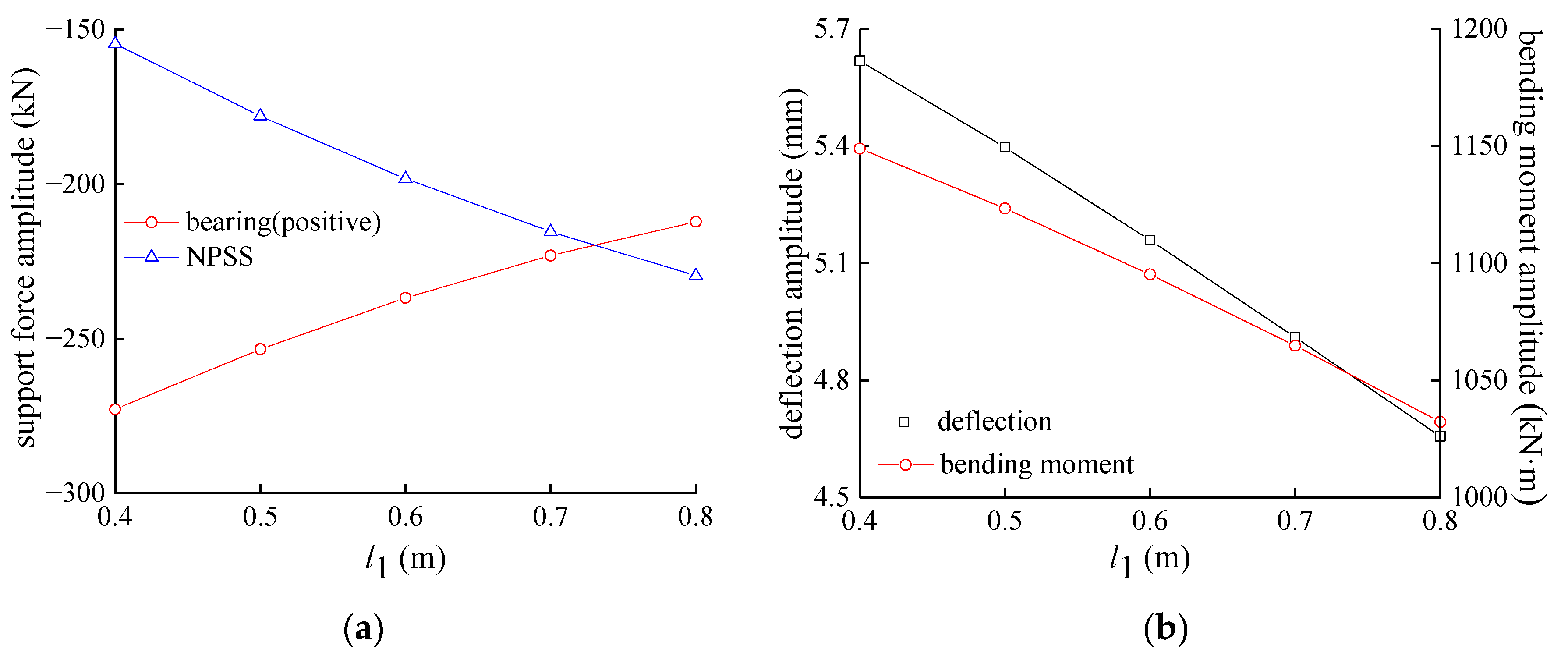
5.3. Influence of the Installation Location

Due to the limitation of the size of the pier top, the study range of l1 is almost small, from 0.4 m to 0.8 m. Under the calculation conditions, the ratio k2/k1 is kept fixed at 0.1. The obtained results have been demonstrated in Figure 16.
As shown in Figure 16a, with the growth of l1, the supporting force amplitudes of the bridge bearing and the NPSS vary approximately linearly, where the positive supporting force amplitude of the bridge bearing lessens and the supporting force amplitude of the NPSS grows. For the case of l1 = 0.73 m, the support forces of the bridge bearing and the NPSS are approximately equal. As the value of l1 ranges from 0.4 m to 0.8 m, the support forces of the bridge bearing and the NPSS demonstrate the changes of 60.7 kN and 75.0 kN, respectively (i.e., the percentage alterations of 22.2% and 48.5%).
The illustrated results in Figure 16b reveal that the midspan deflection and bending moment amplitudes lessen linearly with the increase of l1 such that the reduction rates in order are 2.4 mm/m and 291.8 kN·m/m. As the value of l1 increases from 0.4 m to 0.8 m, the midspan deflection and bending moment amplitudes lessen by 1.0 mm and 116.6 kN·m, respectively, signifying a reduction of 17.1% and 10.1%.
Thus, the installation location of the NPSS plays a vital role in the strengthening effect; nevertheless, in the case of k2/k1 = 0.1, l1 must be greater than 0.7 m to meet the requirements of the bridge deflection.

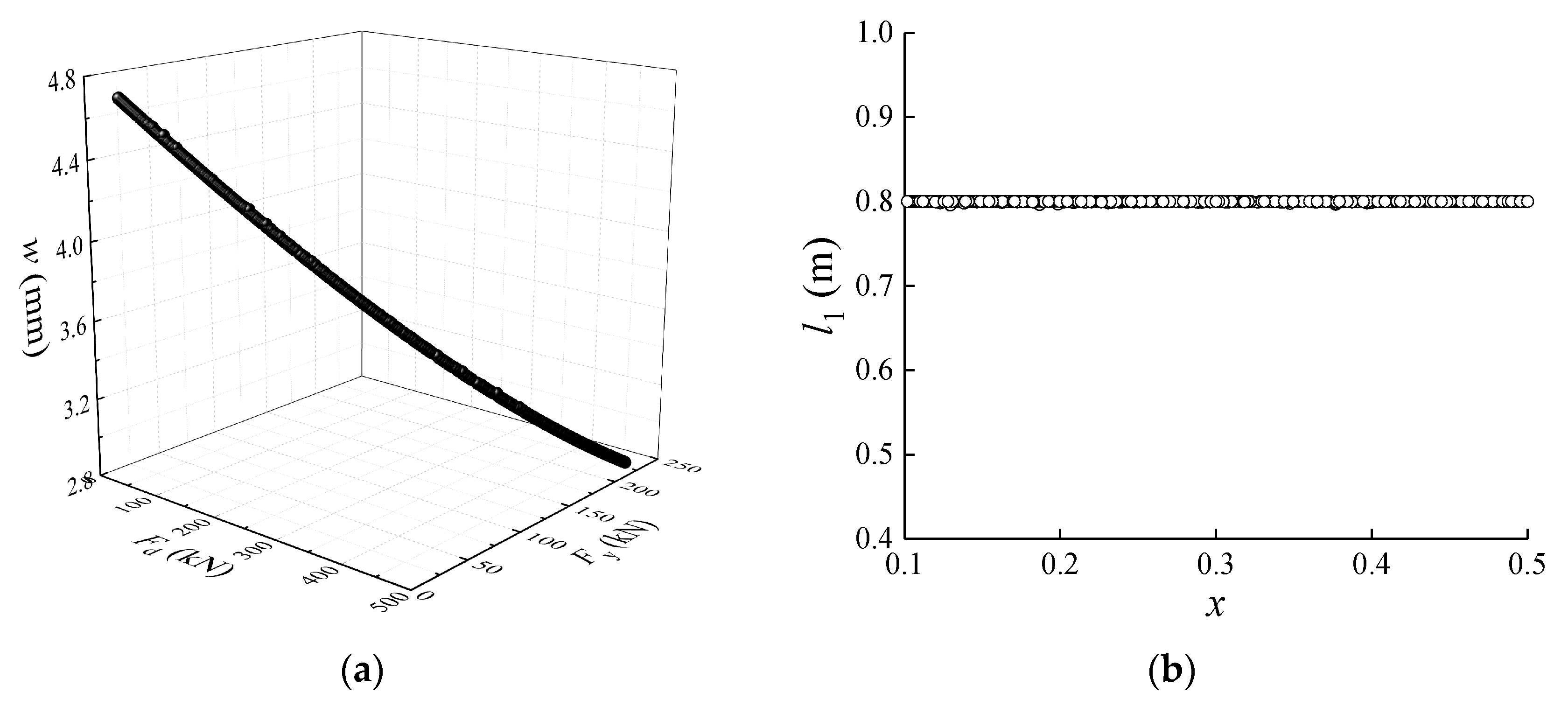
5.4. Parameters Optimization

Although the increase of k2 and l1 is beneficial in reducing both the deflection and bending moment of the beam, it results in a higher support force of the NPSS and a smaller positive support force of the bridge bearing, which is unfavorable to the NPSS. Therefore, the amplitudes of the positive support force of the bridge bearing and the support force of the NPSS should be equal as far as possible. Meanwhile, the midspan deflection and the negative support force of the bridge bearing should be as small as possible to determine the optimal values of k2 and l1. By virtue of the refined calculation model and the numerical test, the RSM is implemented to determine the explicit functional relationship between the mechanical indexes of the bridge with NPSS and support stiffness, and the installation location of NPSS. Thereby,
w = 7.406 4.410 x 3.438 l 1 + 5.331 x 2 + 1.162 l 1 2 4.138 x l 1
F b = 28.929 + 932.019 x 61.521 l 1 1196.027 x 2 262.240 l 1 2 + 1297.991 x l 1 ,
F y = 113.757 + 91.352 x + 407.353 l 1 + 46.588 x 2 360.671 l 1 2 + 433.894 x l 1 ,
where x = k2/k1, w represents the midspan deflection amplitude, Fb denotes the absolute value of the difference between the positive support force amplitude of the bridge bearing and that of the NPSS, and Fy is the negative support force amplitude of the bridge bearing. The multiple correlation coefficient, modified multiple correlation coefficient, and R2 (prediction) of the fitting results are all over 0.95. By taking the minimum of w, Fb, and Fy as the objective functions, a multi-objective optimization model could be constructed as:
Min     Y = w x , l 1 ,   F b x , l 1 ,   F y x , l 1 s . t .       0 w 4.9                     0 F b , F y                                 0.1 x 0.5                     0.4 l 1 0.8
The Pareto optimal boundary of the multi-objective optimization model is determined with the multi-objective evolutionary algorithm NSGA-II, as illustrated in Figure 17a. Figure 17b presents the optimized values of the variables x and l1.
As shown in Figure 17, the Pareto optimal boundary is a spatial curve. Regardless of the value of x, the corresponding value of l1 for the optimal design is fixed at 0.8 m, which is the maximum allowable value. For the optimal boundary given in Figure 16a, the analysis hierarchy process-fuzzy comprehensive evaluation (AHP-FCE) method is employed to determine the reasonable support stiffness of the NPSS for engineering applications. Since w, Fb, and Fy are all negative indicators, the data standardization scheme shown in Equation (11) is adopted. Take midspan deflection amplitude w as an example:
r i = 1 w i max w + 1 max 1 w i max w ,
where wi and ri represent the values before and after data standardization, respectively.
The weight coefficients of w, Fb, and Fy determined based on the AHP-FEC are 0.15, 0.48, and 0.37, respectively. The weight coefficients remain unchanged with the variation of the selected optimal boundary points. At this time, the values of x and l1 associated with the optimal scheme are 0.1018 and 0.8, which means that the support stiffness value is 2.5 × 10⁸ N/m, and the center distance between the bridge bearing and its adjacent NPSS is 0.8 m. According to the optimal factors, the midspan deflection-load curve of the bridge based on the four-point bending test has been presented in Figure 18. The plot of the load-bearing capacity of the strengthened bridge demonstrates an increase of 19.5%. The slope of the curve in the elastic deformation stage of the bridge with the NPSS also rises from 104.7 kN/mm to 126.7 kN/mm, which reveals that the vertical stiffness of the bridge has been enhanced by 21.0%.

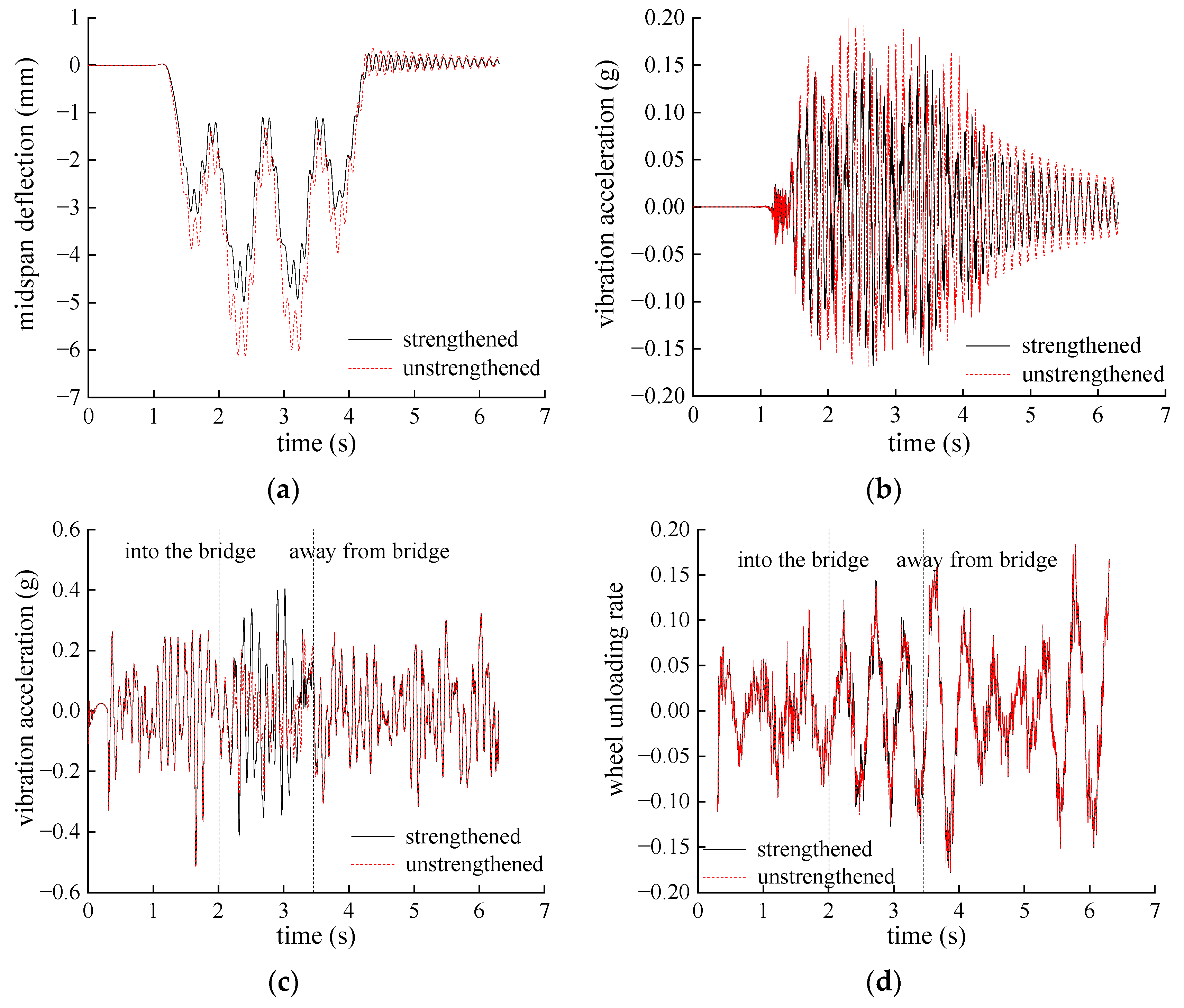
5.5. Dynamic Performance Verification

Since the NPSS chiefly influences the vertical mechanical behavior of the strengthened bridge, the vehicle–track–bridge vertical coupling dynamical model with ANSYS/LS-DYAN software is established to prove the validity of the proposed optimization scheme. The dynamics model illustrated in Figure 19 consists of a vehicle subsystem, a tracking subsystem, a bridge subsystem, and a wheel–rail contact system.
As the span of the simply supported bridge is smaller than the length of a vehicle, the vehicle subsystem is employed to simulate three-car trains. In order to simplify the calculation, the nonlinear materials’ behaviors are ignored. The track vertical irregularity excitation is taken in accordance with the American 5th-grade track spectrum and the running speed is set as 60 km/h. Figure 20 demonstrates the dynamic response of the bridge when the vehicles pass across the bridge.
According to the plotted results in Figure 20, the NPSS has a trivial influence on the trend of dynamic deformation and vibration of the bridge. However, the NPSS can effectively control the midspan dynamic deflection and vibration acceleration amplitude. Through employing the NPSS, the midspan deflection and vibration acceleration amplitudes lessen by 1.16 mm and 0.41 m/s2, which indicates a reduction of 23.4% and 25.2%, respectively. Due to the improvement of the vertical stiffness of the bridge with NPSS, the car’s vertical vibration acceleration and wheel unloading rate intensify by 1.31 m/s2 and 0.01, which still satisfies the demand for heavy-haul train running safety.

6. Conclusions

A new bridge strengthening structure, called NPSS, which can be constructed using an assembly construction method, has been proposed. Both theoretical derivation and numerical simulation have proven that the NPSS can improve the vertical stiffness and load-bearing capacity of existing short-span bridges for heavier axle-load trains. The effect of two key parameters on structural behavior of the bridge has been investigated, and the parameters were also optimized based on a multi-objective optimization model. The major achieved results are summarized as follows:
(1) The excessive support stiffness of the NPSS would cause the support forces of bearing and the NPSS to reverse, which enables the NPSS to bear additional load. The strengthening effect was not significant when the support stiffness of the NPSS was too small. The support stiffness of the NPSS should be controlled within a reasonable range.
(2) The increase in the center distance between the bridge bearing and its adjacent NPSS would result in a more significant strengthening effect. Therefore, if conditions permit, this distance should be increased as much as possible.
(3) The optimal values of the support stiffness and center distance between the bridge bearing and its adjacent NPSS in order are 1.25 × 10⁸ N/m and 0.8 m, which could enhance the load-bearing capacity and the vertical stiffness of the bridge by 19.5% and 21.0%, respectively, and reduce the midspan dynamic deflection amplitude and vertical vibration acceleration amplitude of the bridge by 23.4% and 25.2%, respectively.
Although the strengthening method with the NPSS is verified with the static and dynamic calculation models, field test verification is also necessary. Therefore, the NPSS will be produced and installed for a short-span bridge for heavy-haul railway, and field testing will be carried out to verify the feasibility and effectiveness of the strengthening method with the NPSS.

Author Contributions

Conceptualization, K.X., S.C. and X.W.; Data curation, B.L. and W.D.; Formal analysis, K.X. and B.L.; Funding acquisition, K.X. and S.C.; Investigation, K.X., B.L. and W.D.; Methodology, K.X. and S.C.; Software, K.X. and X.W.; Writing—original draft, K.X.; Writing—review and editing, B.L., S.C. and X.W. All authors have read and agreed to the published version of the manuscript.

Funding

This research was funded by National Natural Science Foundation of China, grant numbers 52008272 and 51978423. This research was also funded by Natural Science Foundation of Hebei Province, grant numbers E2022210046 and E2021210099.

Data Availability Statement

All data and models used during the study appear in the submitted manuscript.

Conflicts of Interest

The authors declare no conflict of interest.

Appendix A

Figure A1 shows the calculating diagram based on Figure 2.
Figure A1. Calculating diagram.
Buildings 13 00876 g0a1
In Figure A1, F1 and F2 represent the support force of the bridge bearing and the NPSS. The bending moments at different positions are expressed by:
M x = F 1 x                                                                                                                                                                                                                           0 x l 1 F 1 x + F 2 x l 1                                                                                                                                                                             l 1 < x L 2 l t l 2 2 F 1 x + F 2 x l 1 F x L 2 + l t + l 2 2                                                                                           L 2 l t l 2 2 < x L 2 l 2 2 F 1 x + F 2 x l 1 F x L 2 + l t + l 2 2 F x L 2 + l 2 2                           L 2 l 2 2 < x L 2
Based on the relation between the second derivative of deflection and the bending moment, the first derivative of deflection and the deflection can be obtained.
x 0 , l 1
E I w x = F 1 2 x 2 + C 1 E I w x = F 1 6 x 3 + C 1 x + C 2 ,
x l 1 , L 2 l t l 2 2
E I w x = F 1 2 x 2 F 2 2 x l 1 2 + C 3 E I w x = F 1 6 x 3 F 2 6 x l 1 3 + C 3 x + C 4 , ,
x L 2 l t l 2 2 , L 2 l 2 2
E I w x = F 1 2 x 2 F 2 2 x l 1 2 + F 2 x L 2 + l t + l 2 2 2 + C 5 E I w x = F 1 6 x 3 F 2 6 x l 1 3 + F 6 x L 2 + l t + l 2 2 3 + C 5 x + C 6 ,
x L 2 l 2 2 , L 2
E I w x = F 1 2 x 2 F 2 2 x l 1 2 + F 2 x L 2 + l t + l 2 2 2 + F 2 x L 2 + l 2 2 2 + C 7 E I w x = F 1 6 x 3 F 2 6 x l 1 3 + F 6 x L 2 + l t + l 2 2 3 + F 6 x L 2 + l 2 2 3 + C 7 x + C 8 ,
where C1C8 are undetermined constants. The curve of the first derivative of deflection and the deflection are continuous at l1, L/2 − ltl2/2 and L/2 − l2/2. The relation among C1~C8 can be determined.
C 1 = C 3 = C 5 = C 7 C 2 = C 4 = C 6 = C 8
Because of the symmetry, the first derivative of deflection is zero for the case of x = L/2.
F 1 2 L 2 2 F 2 2 L 2 l 1 2 + F 2 l t + l 2 2 2 + F 2 l 2 2 2 + C 7 = 0
The above formula can be simplified as:
C 7 = F 1 8 L 2 + F 2 8 L 2 l 1 2 F 2 l t 2 + l 2 2 2 + l 2 l t ,
With the relation among F1, F2 and w(x) and the principle of force balance, Formulas (A8)–(A10) can be obtained.
F 1 = k 1 w 0 F 1 = k 1 E I C 2 ,
F 2 = k 2 w l 1 E I F 2 k 2 = F 1 6 l 1 3 + C 1 l 1 + C 2 ,
F 1 + F 2   = 2 F
Substituting Formulas (A6)–(A8) and Formula (A10) into Formula (A9), Formula (A11) can be obtained.
E I F 2 k 2 = 2 F F 2 6 l 1 3 + 2 F F 2 8 L 2 l 1 + F 2 l 1 8 L 2 + 4 l 1 2 4 L l 1                           F l 1 2 l t 2 + l 2 2 2 + l 2 l t + 2 F E I k 1 F 2 E I k 1
Formula (A11) can be simplified as:
E I k 1 + k 2 k 1 k 2 l 1 8 l 1 2 + 6 L l 1 F 2 = 24 E I k 1 l 1 + 3 L 2 l 2 2 6 l t l t + l 2 4 l 1 2 F
Assume that
A = 12 E I k 1 + k 2 k 1 k 2 l 1 + 6 L l 1 8 l 1 2 B = 24 E I k 1 l 1 + 3 L 2 l 2 2 6 l t l t + l 2 4 l 1 2 ,
then F1, F2 and M(L/2) can be obtained as:
F 2 = B A F , F 1 = 2 B A F ,
M L 2 = F 1 L 2 + F 2 L 2 1 F l t + l 2 2 F l 2 2                         = F L l t l 2 B A l 1
Substituting Formulas (A8) and (A9) into Formula (A2), Formula (A15) can be obtained.
E I w L 2 = F 1 48 L 3 F 2 48 L 2 l 1 3 + F 6 l t + l 2 2 3 + F 48 l 2 3                                 + E I F 2 L 2 k 2 l 1 + 2 F F 2 L l 1 2 12 2 F F 2 E I L 2 k 1 l 1 + 2 F F 2 E I k 1
Substituting Formula (A10), Formula (A13) and Formula (A15) into Formula (A5), Formula (A16) can be obtained.
E I w L 2 = F 1 48 L 3 F 2 48 L 2 l 1 3 + F 6 l t + l 2 2 3 + F 48 l 2 3                                   + E I F 2 L 2 k 2 l 1 + 2 F F 2 L l 1 2 12 2 F F 2 E I L 2 k 1 l 1 + 2 F F 2 E I k 1
Formula (A16) can be simplified as:
w L 2 = E I L k 1 + k 2 2 k 1 k 2 l 1 E I k 1 + l 1 3 6 + L 2 l 1 8 L l 1 2 3 F 2                         + L 4 l 1 2 L 2 24 + E I 2 l 1 L k 1 l 1 + 2 l t + l 2 3 + l 2 3 48 F
Assume that
C = L 4 l 1 2 L 2 24 + E I 2 l 1 L k 1 l 1 + 2 l t + l 2 3 + l 2 3 48 D = E I L k 1 + k 2 2 k 1 k 2 l 1 E I k 1 + l 1 3 6 + L 2 l 1 8 L l 1 2 3 ,
then w(L/2) can be obtained as:
w L 2 = D F 2 + C F = D B A F + C F = C + B A D F E I
In order to guarantee that the support force of the bridge bearing and the resulting force within the NPSS would be in the same direction, F1 should be greater than zero, namely:
F 1 = 2 B A F 0 B 2 A
Substituting A and B into Formula (A19), Formula (A20) can be obtained.
24 E I k 1 l 1 + 3 L 2 l 2 2 6 l t l t + l 2 4 l 1 2 24 E I k 1 + k 2 k 1 k 2 l 1 + 12 L l 1 16 l 1 2 k 2 8 E I l 1 L 2 l 2 2 2 l t l t + l 2 + 4 l 1 l 1 L

References

  1. Holder, D.E.; Csenge, M.V.; Qian, Y.; Dersch, M.S.; Edwards, J.R.; Dyk, B.V. Laboratory Investigation of the Skl-Style Fastening System’s Lateral Load Performance under Heavy Haul Freight Railroad Loads. Eng. Struct. 2017, 139, 71–80. [Google Scholar] [CrossRef]
  2. Guo, F.Q.; Wang, P.J.; Yang, Q.; Yu, Z.W.; Leng, W.M.; Chen, C. Experimental Research on Characteristics of Vertical Dynamic Load on Bridge Pier and Pile Foundation under Heavy-Haul Railway Train. China Civ. Eng. J. 2021, 54, 79–90. [Google Scholar] [CrossRef]
  3. Bonopera, M.; Liao, W.C.; Perceka, W. Experimental–Theoretical Investigation of the Short-Term Vibration Response of Uncracked Prestressed Concrete Members under Long-Age Conditions. Structures 2022, 35, 260–273. [Google Scholar] [CrossRef]
  4. Noble, D.; Nogal, M.; O’Connor, A.; Pakrashi, V. The Effect of Prestress Force Magnitude and Eccentricity on the Natural Bending Frequencies of Uncracked Prestressed Concrete Beams. J. Sound Vib. 2016, 365, 22–44. [Google Scholar] [CrossRef] [Green Version]
  5. Song, L.; Cui, C.X.; Liu, J.L.; Yu, Z.W.; Jiang, L.Z. Corrosion-Fatigue Life Assessment of RC Plate Girder in Heavy-Haul Railway under Combined Carbonation and Train Loads. Int. J. Fatigue 2021, 151, 106368. [Google Scholar] [CrossRef]
  6. Sangiorgio, V.; Nettis, A.; Uva, G.; Pellegrino, F.; Varum, H.; Adam, J.M. Analytical Fault Tree and Diagnostic Aids for the Preservation of Historical Steel Truss Bridges. Eng. Fail. Anal. 2022, 133, 105996. [Google Scholar] [CrossRef]
  7. Chmielewski, R.; Muzolf, P. Analysis of Degradation Process of A Railway Steel Bridge in the Final Period of Its Operation. Struct Infrastruct E. 2023, 19, 537–553. [Google Scholar] [CrossRef]
  8. Scheerer, S.; Zobel, R.; Müller, E.; Senckpiel-Peters, T.; Schmidt, A.; Curbach, M. Flexural Strengthening of RC Structures with TRC—Experimental Observations, Design Approach and Application. Appl. Sci. 2019, 9, 1322. [Google Scholar] [CrossRef] [Green Version]
  9. Kadhim, M.M.A.; Jawdhari, A.; Nadir, W.; Cunningham, L.S. Behaviour of RC Beams Strengthened in Flexure with Hybrid CFRP-Reinforced UHPC Overlays. Eng. Struct. 2022, 262, 114356. [Google Scholar] [CrossRef]
  10. Sohail, M.G.; Wasee, M.; Nuaimi, N.A.; Alnahhal, W.; Hassan, M.K. Behavior of Artificially Corroded RC Beams Strengthened with CFRP and Hybrid CFRP-GFRP Laminates. Eng. Struct. 2022, 272, 114827. [Google Scholar] [CrossRef]
  11. Bazli, M.; Heitzmann, M.; Hernandez, B.V. Hybrid Fibre Reinforced Polymer and Seawater Sea Sand Concrete Structures: A Systematic Review on Short-Term and Long-Term Structural Performance. Constr. Build. Mater. 2021, 301, 124335. [Google Scholar] [CrossRef]
  12. Ekoi, E.J.; Dickson, A.N.; Dowling, D.P. Investigating the Fatigue and Mechanical Behaviour of 3D Printed Woven and Nonwoven Continuous Carbon Fibre Reinforced Polymer (CFRP) Composites. Compos. Part B-Eng. 2021, 212, 108704. [Google Scholar] [CrossRef]
  13. Xiong, Z.; Wei, W.; Liu, F.; Cui, C.Y.; Li, L.J.; Zou, R.; Zeng, Y. Bond Behaviour of Recycled Aggregate Concrete with Basalt Fibre-Reinforced Polymer Bars. Compos. Struct. 2021, 256, 113078. [Google Scholar] [CrossRef]
  14. Crawford, B.; Soto, R.; Lemus-Romani, J.; Astorga, G.; de la Parra, S.M.; Peña-Fritz, A.; Valenzuela, M.; García, J.; de la Fuente-Mella, H.; Castro, C. Investigating the Efficiency of Swarm Algorithms for Bridge Strengthening by Conversion to Tied-Arch: A Numerical Case Study on San Luis Bridge. Iran. J. Sci. Technol. Trans. Civ. Eng. 2021, 45, 2345–2357. [Google Scholar] [CrossRef]
  15. Hosseini, A.; Ghafoori, E.; Al-Mahaidi, R.; Zhao, X.L.; Motavalli, M. Strengthening of A 19th-Century Roadway Metallic Bridge Using Nonprestressed Bonded and Prestressed Unbonded CFRP Plates. Constr. Build. Mater. 2019, 209, 240–259. [Google Scholar] [CrossRef]
  16. Mechtcherine, V. Novel Cement-Based Composites for the Strengthening and Repair of Concrete Structures. Constr. Build. Mater. 2013, 41, 365–373. [Google Scholar] [CrossRef]
  17. Heiza, K.; Nabil, A.; Meleka, N.; Tayel, M. State-of-the Art Review: Strengthening of Reinforced Concrete Structures—Different Strengthening Techniques. Sixth Int. Conf. Nano-Technol. Constr. 2014, 6, 1–24. [Google Scholar]
  18. Pantelides, C.P. Strengthening Techniques: Bridges. In Encyclopedia of Earthquake Engineering; Beer, M., Kougioumtzoglou, I., Patelli, E., Au, I.K., Eds.; Springer: Berlin/Heidelberg, Germany, 2014. [Google Scholar]
  19. Cao, X.Y.; Shen, D.J.; Feng, D.C.; Wang, C.L.; Qu, Z. Seismic Retrofitting of Existing Frame Buildings Through Externally Attached Sub-Structures: State of the Art Review and Future Perspectives. J. Build Eng. 2022, 57, 104904. [Google Scholar] [CrossRef]
  20. Sarno, L.D.; Manfredi, G. Seismic Retrofitting with Buckling Restrained Braces: Application to An Existing Non-Ductile RC Framed Building. Soil Dyn. Earthq. Eng. 2010, 30, 1279–1297. [Google Scholar] [CrossRef]
  21. Cao, X.Y.; Feng, D.C.; Beer, M. Consistent Seismic Hazard and Fragility Analysis Considering Combined Capacity-Demand Uncertainties via Probability Density Evolution Method. Struct. Saf. 2023, 103, 102330. [Google Scholar] [CrossRef]
  22. Liu, Z.N.; Chen, X.C.; Ding, M.B.; Zhang, X.Y.; Lu, J.H. Quasi-Static Test of the Gravity Railway Bridge Pier with A Novel Preventative Seismic Strengthening Technique. Structures 2022, 35, 68–81. [Google Scholar] [CrossRef]
  23. Kang, J.T.; Wang, X.F.; Yang, J.; Du, Y.G. Strengthening Double Curved Arch Bridges by Using Extrados Section Augmentation Method. Constr. Build. Mater. 2013, 41, 165–174. [Google Scholar] [CrossRef]
  24. Chen, X.Y.; Fan, P.Y.; Gao, H.S.; Qian, W.; Jiang, S.H. Application of External Prestressing Combined with Enlarged Section Method to Reinforce T-Beam of Approach Bridge to Reduce Seawater Corrosion. Desalin. Water Treat. 2022, 267, 161–166. [Google Scholar] [CrossRef]
  25. Tian, J.; Wu, X.W.; Tan, X.; Wang, W.W.; Hu, S.W.; Du, Y.F.; Yuan, J.Y.; Huang, W.T.; Huang, X. Experimental Study and Analysis Model of Flexural Synergistic Effect of Reinforced Concrete Beams Strengthened with ECC. Constr. Build. Mater. 2022, 352, 128987. [Google Scholar] [CrossRef]
  26. He, Y.L.; Wang, K.; Cao, Z.Y.; Zheng, P.J.; Xiang, Y.Q. Reinforcement Analysis of an Old Multi-Beam Box Girder Based on a New Embedded Steel Plate (ESP) Strengthening Method. Materials 2022, 15, 4353. [Google Scholar] [CrossRef]
  27. Zhang, K.X.; Qi, T.Y.; Zhu, Z.M.; Xue, X.W. Strengthening of A Reinforced Concrete Bridge with A Composite of Prestressed Steel Wire Ropes Embedded in Polyurethane Cement. J. Perform. Constr. Facil. 2021, 35, 04021063. [Google Scholar] [CrossRef]
  28. Kim, S.H.; Park, J.S.; Jung, W.T.; Kim, T.K.; Park, H.B. Experimental Study on Strengthening Effect Analysis of A Deteriorated Bridge Using External Prestressing Method. Appl. Sci. 2021, 11, 2478. [Google Scholar] [CrossRef]
  29. Aksoylu, C.; Yazman, S.¸.; Özkılıç, Y.O.; Gemi, L.; Arslan, M.H. Experimental Analysis of Reinforced Concrete Shear Deficient Beams with Circular Web Openings Strengthened by CFRP Composite. Compos. Struct. 2020, 249, 112561. [Google Scholar] [CrossRef]
  30. Naser, M.Z.; Hawileh, R.A.; Abdalla, J.A. Fiber-Reinforced Polymer Composites in Strengthening Reinforced Concrete Structures: A Critical Review. Eng. Struct. 2019, 198, 109542. [Google Scholar] [CrossRef]
  31. Yuhazri, M.Y.; Zulfikar, A.J.; Ginting, A. Fiber Reinforced Polymer Composite as a Strengthening of Concrete Structures: A Review. IOP Conf. Ser. Mater. Sci. Eng. 2022, 1003, 012135. [Google Scholar] [CrossRef]
  32. Siddika, A.; Mamun, M.A.A.; Ferdous, W.; Alyousef, R. Performances, Challenges and Opportunities in Strengthening Reinforced Concrete Structures by Using FRPs—A State-of-the-Art Review. Eng. Fail. Anal. 2020, 111, 104480. [Google Scholar] [CrossRef]
  33. Zhou, C.D.; Ma, X.; Zhang, X.; Tian, M.W.; Wang, P.G. Mechanical Properties of Double-T Railway Bridges by Transforming Simply Supported into Continuous System. J. Cent. South Univ. 2018, 49, 703–710. [Google Scholar]
  34. Xu, Z.; Chen, B.C.; Zhuang, Y.Z.; Tabatabai, H. Rehabilitation and Retrofitting of a Multi Span Simply-Supported Adjacent Box Girder Bridge into a Jointless and Continuous Structure. J. Perform. Constr. Facil. 2018, 32, 04017112. [Google Scholar] [CrossRef]
  35. Hu, T.M.; Huang, C.K.; Chen, X.F.; Liang, Z.Y. Fatigue Experiment of Concrete Bridges Strengthened by Simple-Supporting to Continuous Construction Method. China J. Highw. Transp. 2010, 23, 76–83. [Google Scholar]
  36. Song, Y.F.; Hu, W.L.; Yuan, Y.G.; Ren, S.P. Strengthening Prestressed Concrete Box Girder Bridge by Upgrading Structural System. J. Perform. Constr. Facil. 2020, 34, 04019103. [Google Scholar]
  37. Zhang, W.X.; Wang, Z.; Wang, P.L.; Chen, H.T. Analysis of Effect of Using Added Self-Anchored Suspension Bridge to Strengthen Continuous Box Girder Bridge. World Bridg. 2017, 45, 76–81. [Google Scholar]
  38. Chen, C.; Yang, C.Q.; Pan, Y.; Zhang, H.L.; Backer, H.D. Parameters Analysis and Design of Transverse Connection Strengthening Prestressed Concrete T-Girder Bridge. Struct. Concr. 2021, 22, 3385–3395. [Google Scholar] [CrossRef]
  39. Hou, P.; Yang, J.; Pan, Y.; Ma, C.J.; Du, W.P.; Yang, C.Q.; Zhang, Y. Experimental and Simulation Studies on the Mechanical Performance of Concrete T-Girder Bridge Strengthened with K-Brace Composite Trusses. Structures 2022, 43, 479–492. [Google Scholar] [CrossRef]
  40. Jiang, L.Z.; Long, W.G.; Yu, Z.W.; Chen, L.K.; Li, L. Dynamic Response Analysis of Heavy-Haul Railway Bridge Strengthened by Bonding Assisted Steel Beams. J. Hunan City Univ. 2013, 40, 28–33. [Google Scholar]
  41. ANSYS Release: 19.0. January, 2018. ANSYS Inc. Available online: https://www.sohu.com/a/220292909_722157 (accessed on 13 March 2023).
  42. TB 10015-2012; Code for Design of Railway Continuous Welded Rail. China Railway Publishing House: Beijing, China, 2013.
  43. Yin, C.F.; Wei, B. Numerical Simulation of a Bridge-Subgrade Transition Zone Due to Moving Vehicle in Shuohuang Heavy Haul Railway. J. Vibroeng. 2013, 15, 1041–1047. [Google Scholar]
  44. TB 10625-2017; Code for Design of Heavy Haul Railway. China Railway Publishing House: Beijing, China, 2017.
Figure 1. Schematic representation of the proposed NPSS. (a) Compositions; (b) installation.
Buildings 13 00876 g001
Figure 2. Schematic representation of a simplified mechanical model.
Buildings 13 00876 g002
Figure 3. Refined calculation model. (a) Model outline; (b) skeleton frame of the steel bars.
Buildings 13 00876 g003
Figure 4. Cross-section of the test beam (unit: mm).
Buildings 13 00876 g004
Figure 5. Detailing of steel bars. (a) Midspan section; (b) stressed steel bars of midspan section; (c) center half section of beam stem (unit: mm).
Buildings 13 00876 g005
Figure 6. Schematic view of four-point bending test (unit: cm).
Buildings 13 00876 g006
Figure 7. Field test. (a) Installation of the test beam; (b) loading with jacks.
Buildings 13 00876 g007
Figure 8. Uniaxial stress–strain relationship of the concrete. (a) Compression; (b) tension.
Buildings 13 00876 g008
Figure 9. The achieved results from the test and the calculation model.
Buildings 13 00876 g009
Figure 10. Relation between the error and yield strength.
Buildings 13 00876 g010
Figure 11. Parameters of the applied load (unit: cm).
Buildings 13 00876 g011
Figure 12. The calculated results with and without NPSS. (a) Midspan deflection; (b) midspan bending moment; (c) support force.
Buildings 13 00876 g012
Figure 13. Contour plots of the plastic strain of the beam.
Buildings 13 00876 g013
Figure 14. Effects of the support stiffness. (a) Support force; (b) deflection and bending moment amplitudes.
Buildings 13 00876 g014
Figure 15. Envelope graph of the bending moment for various levels of k2/k1.
Buildings 13 00876 g015
Figure 16. Effects of the installation location. (a) Support force; (b) deflection and bending moment amplitudes.
Buildings 13 00876 g016
Figure 17. The plotted results of the multi-objective optimization. (a) Pareto optimal solution; (b) optimization variable value.
Buildings 13 00876 g017
Figure 18. The midspan deflection-load curves for the cases of with and without NPSS.
Buildings 13 00876 g018
Figure 19. A dynamical finite-element-based model for vehicle–track–bridge system.
Buildings 13 00876 g019
Figure 20. Dynamic responses. (a) Midspan deflection; (b) midspan’s vibration acceleration; (c) car’s vibration acceleration; (d) wheel unloading rate.
Buildings 13 00876 g020
Table 1. Information of the model.
ComponentElement TypeMesh SizesAmount
railbeam1880.01–0.09 m2574
sleepershell630.05 m16,223
beamsolid1850.05 m134,750
steel barsmesh200/reinf2640.05 m55,847
fastenercombin14/combin39-208/104
ballast bedcombin14/combin39-39,310/19,655
bearingcombin14/combin39-196
NPSScombin39-196
Table 2. Parameters of sensors.
NameModelRangeSensitivityAccuracy
pressure sensorJMZX34200–2000 kN2.0 mV/V2 kN
displacement sensor (bearings)CDP-100–10 mm1000 με/mm0.001 mm
displacement sensor (midspan)SDP-50C0–50 mm100 με/mm0.01 mm
Table 3. Calculation parameters of the model under investigation.
TypeParameterValueTypeParameterValue
steel barsYoung’s modulus (Pa)2.1 × 10¹¹bridge
section
area (m2)1.18
Poisson’s ratio0.3vertical moment of inertia (m4)0.087
yield strength (MPa)400/300single
bearing
length × width × height (m)0.3 × 0.3 × 0.05
tangent modulus (Pa)1.6 × 10⁹Young’s modulus (Pa)6.84 × 10⁸
diameter (mm)8–25vertical stiffness (N/m)1.23 × 109
Disclaimer/Publisher’s Note: The statements, opinions and data contained in all publications are solely those of the individual author(s) and contributor(s) and not of MDPI and/or the editor(s). MDPI and/or the editor(s) disclaim responsibility for any injury to people or property resulting from any ideas, methods, instructions or products referred to in the content.

