Article

Prediction of Shear Strength for Steel-Fiber High-Strength Concrete Corbels with the Softened Strut-and-Tie Model

1
School of Civil Engineering and Communication, North China University of Water Resources and Electric Power, Zhengzhou 450046, China
2
Engineering Technology Research Center for Structural Vibration Control and Health Monitoring of Henan Province, Zhengzhou 450046, China
3
School of Civil and Transportation Engineering, Henan University of Urban Construction, Pingdingshan 467036, China
*
Author to whom correspondence should be addressed.
Buildings 2023, 13(4), 1107; https://doi.org/10.3390/buildings13041107
Submission received: 3 April 2023 / Revised: 15 April 2023 / Accepted: 20 April 2023 / Published: 21 April 2023
(This article belongs to the Section Building Materials, and Repair & Renovation)

Abstract

:
On the basis of the test results of nine steel-fiber high-strength concrete corbel specimens subjected to a vertical load, the influence of the steel fiber content on the shear performance of corbels was analyzed. The softened strut-and-tie model (SSTM) was used to analyze the shear strength of steel-fiber high-strength concrete corbels, taking into consideration the shear contribution of steel fibers. A calculation model for the shear strength of steel-fiber high-strength concrete corbels is proposed, and a database for 26 steel-fiber high-strength concrete corbels was created by using the model. The results obtained according to the codes ACI318-19, EC2, CSA A23.3-19 and the softened strut-and-tie model were compared with the experimental values to verify the rationality of the model. The findings showed that steel fiber can effectively limit the crack width and improve the crack morphology. The overall average value of the ratio between the experimental and the predicted strengths of the model was 1.082, and the variance was 0.004. The values predicted with the proposed calculation model were closer to the experimental values than those calculated according to the codes. This study provides a definite mechanical model that can reveal the shear mechanism of steel-fiber high-strength concrete. It can reasonably predict the shear strength of steel-fiber high-strength concrete corbels.

Graphical Abstract

1. Introduction

Corbels are cantilever structural elements that are used to compensate for beams in reinforced concrete structures [1,2]. They are commonly used in reinforced concrete constructions, often utilized for vertical loads and sometimes for horizontal loads. With a shear-span-to-depth ratio of less than 1, their mechanical performance is similar to that of deep beams [3]. Those are often used in discontinuity regions (D-regions) of concrete structures, where the assumption of the simple bending theory may not be applicable [4,5]. On the other hand, steel fiber-reinforced concrete is a new type of composite material formed by adding steel fiber to a concrete mix, which can play promote toughening, strengthening and crack resistance [6]. Adding steel fiber to corbels can improve the shear resistance of a structure, effectively enhancing the ductility and bearing capacity of its reinforced concrete members [7,8]. The discreteness of steel-fiber materials further complicates the analysis of corbel forces. Therefore, studying the shear performance of steel-fiber high-strength concrete corbels is of great significance for practical engineering.
A series of studies have focused on the shear-bearing capacity of steel-fiber concrete corbels. Fattuhi [9] conducted an analysis of the shear capacity of fiber-reinforced corbels based on bending and truss models, building upon experimental data. It was concluded that the bending model is more accurate than the truss model in predicting the bearing capacity of fiber-reinforced corbels under bending, and the truss model is suitable for predicting the bearing capacity of fiber-reinforced corbels undergoing various types of stress. Ahmet et al. [10] used a support vector machine to forecast the ultimate shear strength of steel-fiber concrete corbels and compared the prediction results with those obtained using the model proposed by Fattuhi. Kurtogl et al. [11] utilized the symbolic regression method to establish a shear-bearing capacity calculation formula for stirrup-reinforced steel-fiber concrete corbels, based on existing test results. However, the empirical formula obtained through the regression analysis of experimental data lacks a clear mechanical model. Campione et al. [12] proposed a truss model that considered steel fibers. Based on this, Saddam et al. [13] tested 13 steel-fiber concrete corbels, compared and analyzed the test results with the shear-bearing capacity calculated by the model and found that the model calculation results were in good agreement with the test results. Gao et al. [14,15,16] conducted both experimental research and a theoretical analysis on 22 steel fiber-reinforced concrete corbels. In their studies, they proposed a calculation model for the normal-section cracking load, diagonal-section cracking load and shear-bearing capacity of steel-fiber concrete corbels. Gao et al. [17] tested two reinforced concrete corbels and five reinforced steel-fiber concrete corbels and used the softening truss theory to calculate the ultimate bearing capacity of steel-fiber concrete corbels. This model assumes that the internal stress state is uniform, but the internal stress flow changes greatly under the action of a load. Therefore, this model assumes a uniform internal stress state, which is not consistent with reality, as the internal stress flow changes greatly under the action of a load. To address this deficiency, the strut-and-tie model was adopted by the American ACI318-19 code [18], the European EC2 code [19] and the Canadian CSA A23.3-19 [20] code for shear-bearing capacity determination. Nevertheless, the influence of steel fibers on shear capacity is not considered in these codes. Mustafa et al. [21] proposed a tension–compression bar model for the determination of the ultimate shear capacity of steel fiber-reinforced concrete corbels by comprehensively considering the influence of concrete strength, fiber volume, fiber aspect ratio and the ratio of the main reinforcement to the horizontal stirrup. However, the model did not consider the softening phenomenon of concrete under compression. Hwang et al. [22] proposed the softened strut-and-tie model, which not only considers the softening effect of concrete but also satisfies the equilibrium conditions, constitutive laws and compatibility conditions and has been widely applied for deep beams, corbels and beam–column joints.
The aim of this research was to investigate the shear capacity of nine steel-fiber high-strength concrete corbels under a vertical load. The contribution of the steel fibers to the shear resistance mechanism of the corbels was determined based on the softened strut-and-tie model. A calculation model for the shear capacity of steel-fiber high-strength concrete corbels is proposed. We predicted the shear capacity of 26 steel-fiber high-strength concrete corbels, including the test specimens and literature data [23], and the prediction results were compared with the calculation results based on ACI318-19, EC2, CSA A23.3-19 and SSTM [24] to validate the accuracy and rationality of the proposed model.

2. Experimental

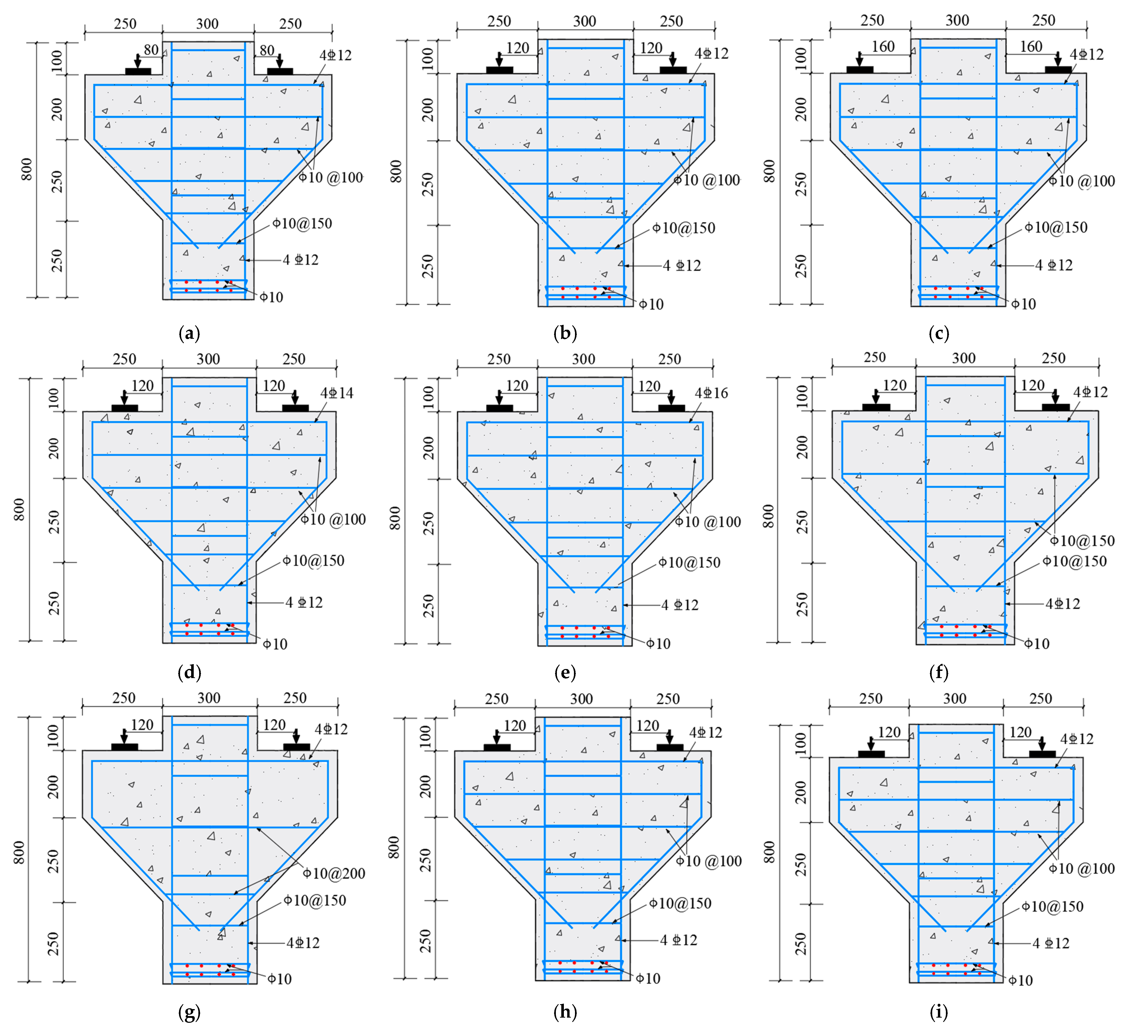
2.1. Specimens Details

A total of 9 steel-fiber high-strength concrete corbel specimens, labeled MC01–MC09, were used in the experiment. Figure 1 indicates the detailed dimensions and the reinforcement of the corbel specimens. The design parameter variables included the shear span-to-depth ratio λ, the main reinforcement ratio ρs, the stirrup reinforcement ratio ρsh and the steel fiber content ρf. The detailed design parameters of corbels are shown in Table 1.

2.2. Mechanical Properties of the Material

All specimens used were made of commercial concrete with a strength grade of C60 and were poured directly on site. Additionally, six cube test blocks measuring 150 mm × 150 mm × 300 mm were used for testing the axial compressive strength and the compressive elastic modulus of steel-fiber high-strength concrete during pouring. Table 2 shows the measured mechanical properties. HRB400- and HPB300-grade rebars were used for the longitudinal and stirrup reinforcement of the specimens, respectively. The measured mechanical properties of the different types of rebar are shown in Table 3.

2.3. Experimental Results and Analysis

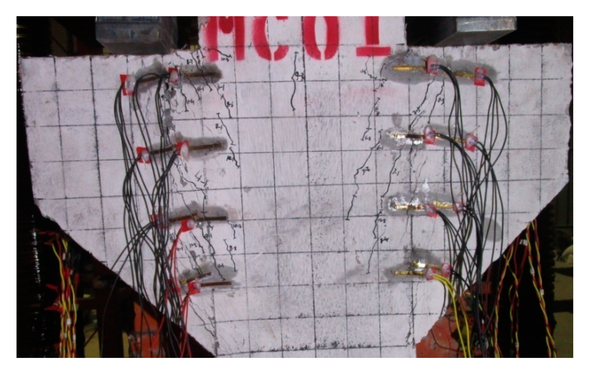
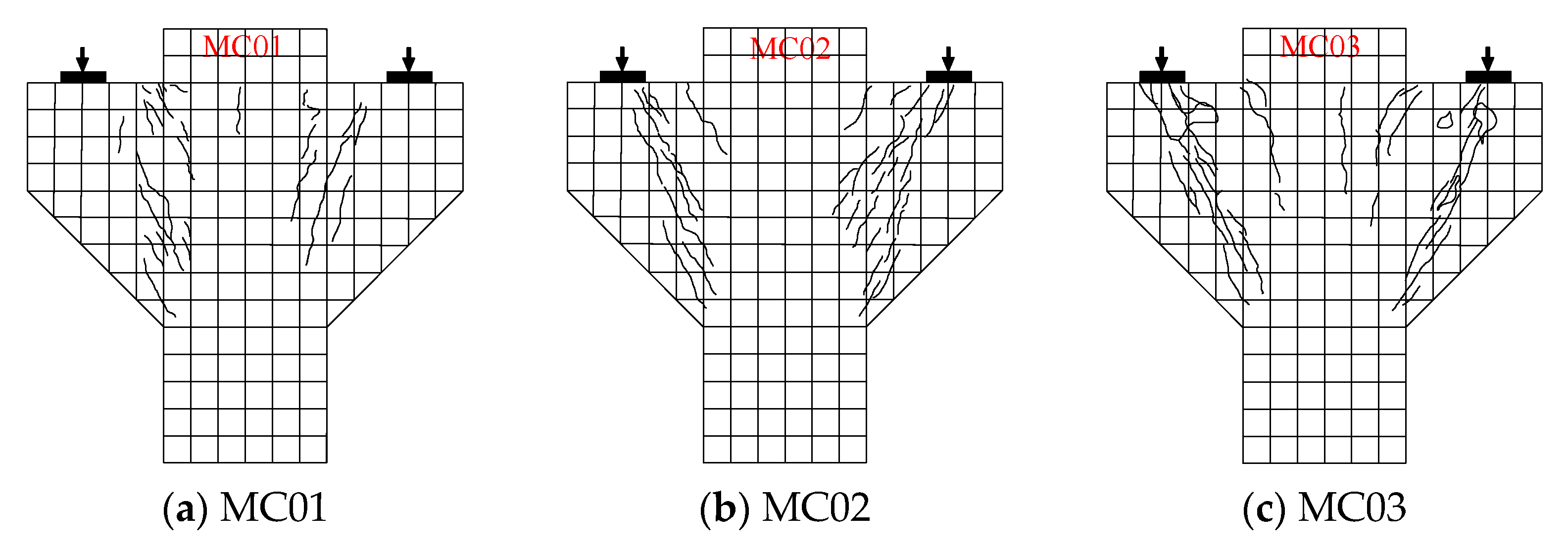
2.3.1. Failure Behavior of the Specimens

Figure 2 displays the failure patterns of the steel-fiber high-strength concrete corbel specimens. When the load was applied and reached 19%~30% of the ultimate load, a vertical positive crack first appeared at the junction of the upper column of the corbel. At this stage, both the steel fiber-reinforced concrete and the main reinforcement were in the elastic working stage. As the load increased to 30%~50% of the ultimate load, diagonal cracks began to form in the belly of the corbel and continued to extend upward and downward along the direction of the diagonal strut. A large number of diagonal cracks appeared and expanded rapidly. In this case, the steel fibers played a role in limiting the macrocracks by acting as a micro-reinforcement. The tensile stress was mainly borne by the reinforcement, steel fibers and concrete. When the ultimate load was applied, the diagonal strut concrete of the corbel was crushed, resulting in corbel failure.
Table 4 presents the failure results of steel-fiber high-strength concrete corbel specimens, where normal-section cracking load, diagonal-section cracking load and ultimate load are denoted as V cr N , V cr D and Vu, respectively.
In Table 4, it appears that the failure modes of steel-fiber high-strength concrete corbels mainly presented the two typical forms of diagonal shear failure and diagonal compression failure. As the shear span-to-depth ratio increased, the shear-bearing capacity of the corbels obviously decreased, and the diagonal compression failure gradually transformed into diagonal shear failure. The failure mode of the specimens did not change when increasing the steel fiber content, the main reinforcement ratio and the stirrup reinforcement ratio.

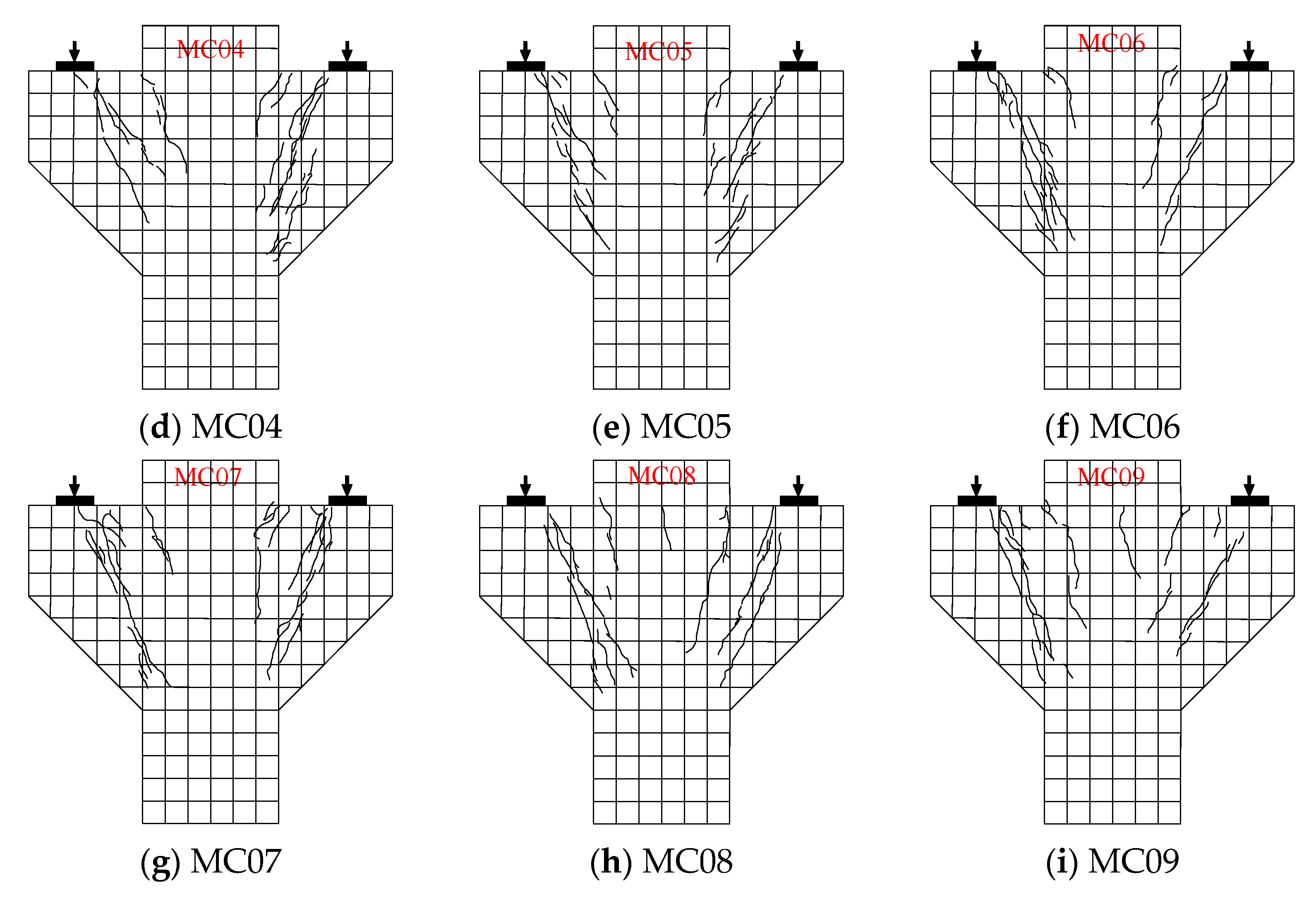
2.3.2. Cracking Responses

The crack distribution of the specimens is shown in Figure 3. It can be seen that the cracks that appeared when the corbel was incorporated into the steel-fiber concrete were tiny. The reason is that the corbel specimen with steel fibers continued to transmit the tensile stress even after the appearance of cracks, relying on the bridging effect of the steel fibers between the cracks. The external manifestation of this phenomenon was that multiple cracks appeared on the surface of the specimen [25,26]. We further explored the effect of steel fibers on cracks. As the steel fiber content increased from 0% to 0.75% and 1.5% (Figure 3b,h,i), the crack morphology changed significantly, and the crack area of the specimen gradually became larger, while the crack width decreased. It showed that the steel fibers had an obvious strengthening and toughening effect on concrete and could effectively improve the cracks. In addition, with the same steel fiber content, the fracture morphology remained basically similar.

3. Establishment of a Shear Capacity Model

More stirrups are present in the shear members of reinforced concrete; therefore, the increase of the stirrup ratio has a little effect on the improvement of the shear capacity. However, the adoption of steel-fiber concrete can modify the concrete and improve the shear capacity. By replacing some stirrups with steel fibers it is possible to alleviate the reinforcement density [27]. The above experiments showed that the steel-fiber high-strength concrete corbel was not cracked, and the compression force was initially borne by the concrete. As cracks appeared, the ability of the concrete to withstand the compression force gradually decreased. Due to the bonding force between the concrete and the steel fibers, the tensile force borne by the steel fibers increased. The enhanced bonding force between the concrete and the steel fibers could also strengthen the bonding force between the steel-fiber concrete and the steel bars, which could limit the development of cracks, directly bearing the tensile force. This led to the design of a strut-and-tie model, as depicted in Figure 4, comprising a diagonal mechanism and a horizontal mechanism. The diagonal mechanism involves concrete in the compression zone, and the horizontal mechanism involves a horizontal tie and two flat struts. The horizontal tie consisted of both stirrups and steel fibers. Therefore, the strut-and-tie model was obtained. Figure 4 shows the features of the diagonal and horizontal mechanisms in the softened strut-and-tie model. The diagonal mechanism involved the concrete in the compression zone, while the horizontal mechanism involved a horizontal tie and two flat struts. The horizontal tie consisted of the stirrup and the steel fibers.
The value of the inclination θ (Figure 4a) between the diagonal strut and the horizontal axial direction is:
θ = tan 1 ( j h 0 a )
where a represents the shear span value, which is defined as the distance to the vertical load Vcv; h0 denotes the effective depth of the corbel section; jh0 is the lever arm, which is the main reinforcement of the corbel against the resultant compressive stress of the concrete compression zone.
The lever arm jd of a singly reinforced rectangular section can be written according to the linear bending theory, which is expressed as follows:
j h 0 = h 0 k h 0 3
where kh0 represents the depth of the section compression zone; k is a coefficient obtained from Equation (3):
k = ( n ρ ) 2 + 2 n ρ n ρ
where n represents the elastic modular ratio, that is, n = Es/Ec; Es is the elastic modulus of steel; Es is the elastic modulus of concrete; ρ is the ratio of the primary tensile reinforcement.
The corbel specimens were cracked, assuming that the direction of the main compressive stress of steel-fiber concrete was consistent with that of the diagonal concrete strut. The effective concrete diagonal strut area Astr can be expressed as:
A str = a s × b
where as is the steel fiber diagonal strut height, the value of b can be considered as equal to the width of the corbel, which represents the width of the diagonal strut, and as is calculated by Equation (5):
a s = k h 0

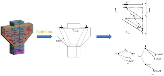
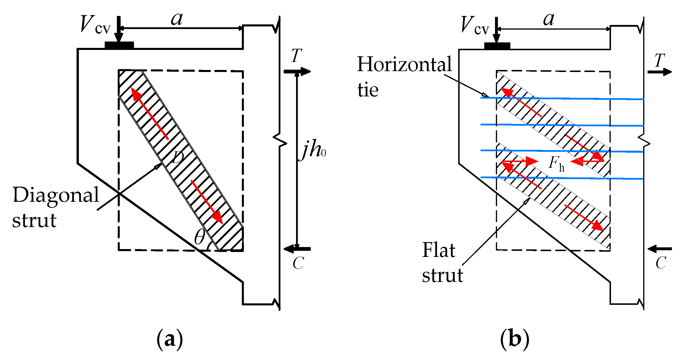
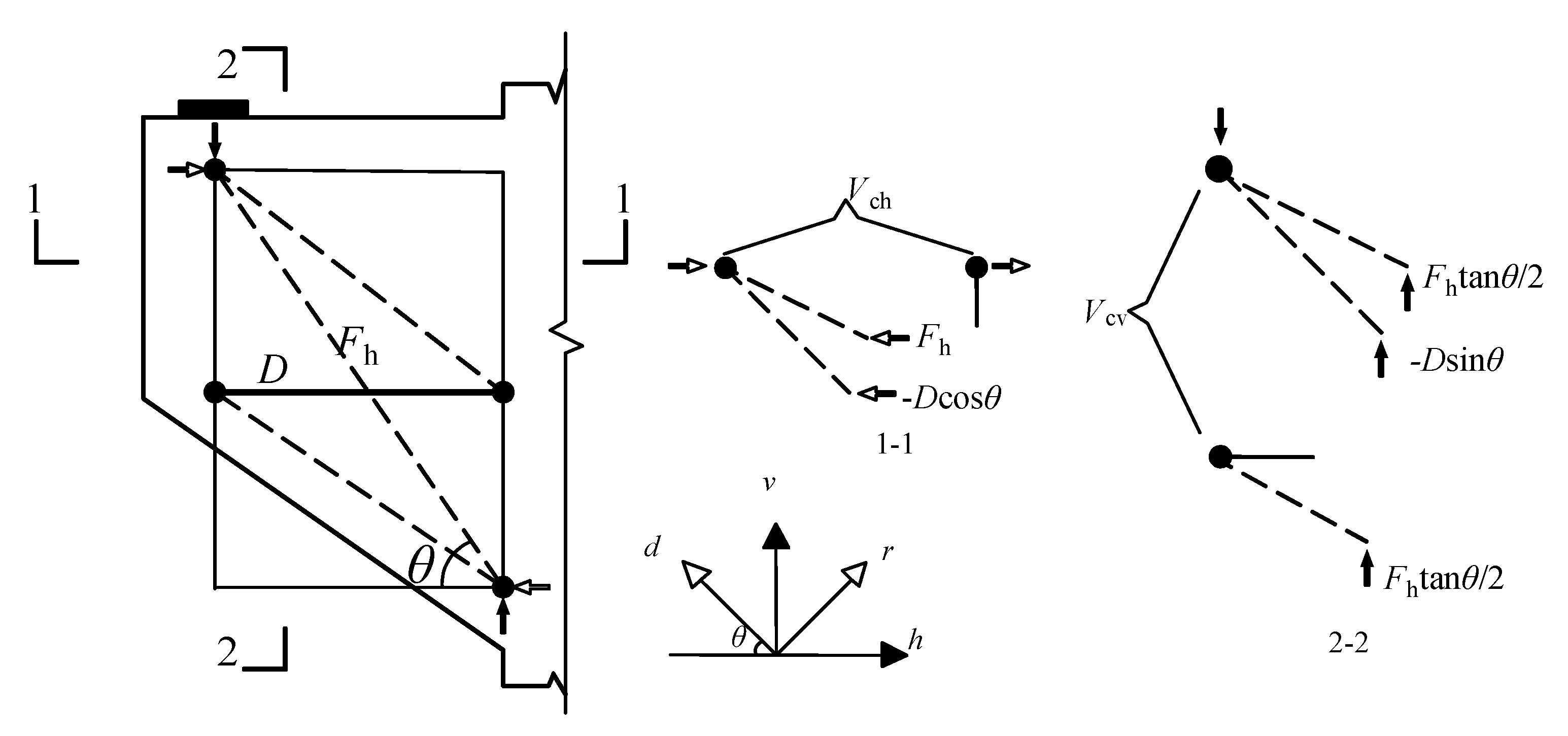
3.1. Equilibrium Conditions

The internal forces of the softened strut-and-tie model are shown in Figure 5. The resistance force of the vertical shear force can be expressed as:
V cv = D sin θ + F h tan θ
where D is the compression force in the diagonal strut; Fh is the tension force in the horizontal ties. Similarly, the horizontal force can be expressed as:
V ch = D cos θ + F h
The steel fibers’ tension is in the horizontal direction of the small reinforcement incorporated into the horizontal tie, and the stirrups and steel fibers together resist the tensile force. The tension in the horizontal tie involves both the stirrups and the steel fibers and can be expressed as:
F h = F s , h + F sf , h   = A s , h f s , h + A sf , h f sf
where Fs,h is the force of the horizontal stirrup tie tension; Fsf,h is the force of the horizontal steel fiber tie tension; fs,h and fsf are the stirrups and steel fiber tensile strength, respectively.
The expression for an equivalent section area of the horizontal steel fiber tie, Asf,h, is as follows:
A sf , h = n A sf = ρ s , f b h sin θ
Equation (9) indicates that the steel fiber is equivalent to the horizontal distribution of the reinforcement; ρs,f = ηρf, along the horizontal direction can be considered as the reinforcement rate, η is the direction coefficient of the steel fiber, and is 0.41 [28]; n is the number of steel fibers. Asf is the cross-section area of an individual steel fiber.
The vertical shear force is proportionally distributed between the two shear mechanisms [29], and the proportional relationship is as follows:
D sin θ : F h tan θ = R d : R h
where Rd/Rh is the ratio of the shear force of the corbel resisted by the diagonal and the horizontal mechanisms, respectively.
By combining (6) and (9), the values of D and Fh can be calculated
D = 1 sin θ × R d R h + R d × V cv
F h = 1 tan θ × R h R h + R d × V cv
The softened strut-and-tie model is a statically indefinite model, and Rd and Rh cannot be calculated directly through the equilibrium equation and should be determined according to the relative stiffness of the shear mechanism [24], which can be expressed as:
R d = 1 γ h
R h = γ h
γ h = 2 tan θ 1 3
where γh is the ratio between the horizontal tie and the horizontal shear force in the absence of a vertical tie.
The total maximum compressive stress caused by the diagonal strut and the flat strut is σd. When the maximum compressive stress of the core area σd,max reaches the ultimate strength of concrete and the shear capacity of the corbel, the expression is:
σ d , max = 1 A str D F h cos θ ( 1 sin 2 θ 2 )

3.2. Constitutive Laws

The compressive stress–strain relationship of cracked steel fiber concrete [30] can be expressed as:
σ d = ζ f c [ 2 ( ε d ζ ε 0 ) ( ε d ζ ε 0 ) 2 ]             ε d ζ ε 0 1 σ d = ζ f c [ 1 ( ε d / ζ ε 0 1 2 / ζ 1 ) 2 ]             ε d ζ ε 0 > 1
where σd is the average stress in the principal direction of d in concrete; ζ is the steel-fiber concrete softening coefficient; εd is the average strain in the principal direction of d in concrete; ε0 is the peak strain in the steel-fiber concrete, which can be obtained by the following formula:
ε 0 = 0 . 002 + 0 . 001 ( f c 20 80 )
The softening coefficient of steel-fiber high-strength concrete is not the same as that of ordinary-strength steel-fiber concrete, as reported [31]:
ζ = 5 . 8 f c 1 1 + 600 ε r
Assuming the stress–strain relationship of the steel bars satisfies the elastic–perfectly plastic model, it can be described by the following equation:
f h = E s ε h             ε h < ε yh f h = f yh             ε h ε yh
where fh and εh are the tensile stress and the strain in the reinforcement, respectively; fyh and εyh are the yield stress and the strain in the horizontal stirrups, respectively.
The stress–strain relationship of steel fibers is as follows:
f sf = E sf ε sf
where Esf is the elastic modulus of the steel fiber; εsf is the strain of the steel fiber.
Due to the high tensile strength of the steel fiber, the steel fiber tends to be pulled out rather than broken when the corbels are sheared. Therefore, the tensile strength of the steel fiber cannot be directly utilized when calculating the tensile strength in experimental conditions but relies on the maximum bond strength between the steel fiber and the concrete matrix. fsf should satisfy the following relationship
A sf f sf λ ds A spf τ sf , max
where λds is the influencing factor of the steel fiber type, i.e., 0.5, 0.75 and 1.0 for long and straight, wavy and crooked steel fibers [32]; Aspf is the surface area of the steel fiber (Aspf = 0.25πlsfdsf, where lsf is the length of the steel fiber, and dsf is the diameter of the steel fiber); τsf,max is the bond strength coefficient of steel fiber and concrete and is 2.5fc′ [33].
From Equation (18) we have:
f sf = ( l sf d sf ) λ ds τ sf , max
According to the stress–strain relationship between steel and steel fiber, the relationship between tension and strain in the horizontal tie can be obtained by
F h = A s , h E s ε h + A sf , h f sf F yh
where As,h is the area of the horizontal stirrup tie, and Asf,h is the area of the steel fiber tie. Fyh is the yield force in the horizontal direction.

3.3. Compatibility Conditions

The two-dimensional membrane element should satisfy the Mohr circle compatibility condition, which considers the average strains of different coordinate systems. The coordination equation is
ε r + ε d = ε h + ε v
where εr is the principal tensile strain; εd is the principal compressive strain; εv and εh are the vertical and horizontal strains, respectively.

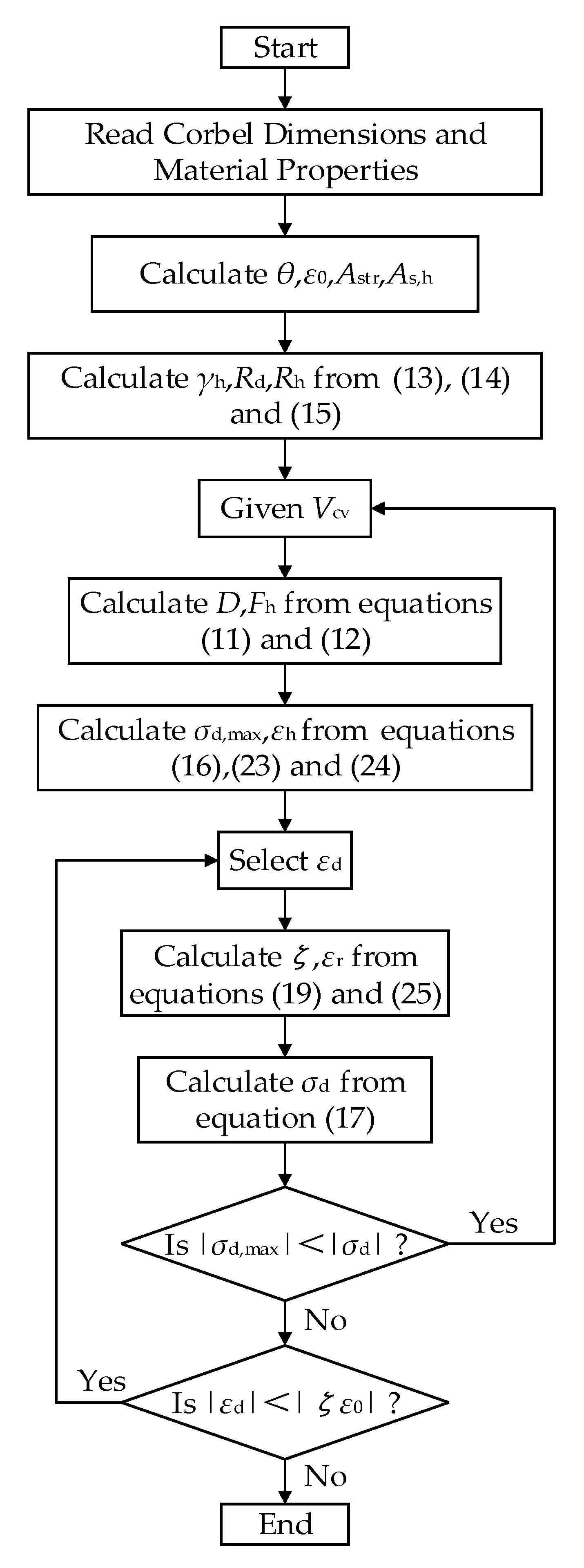
3.4. Solution Process

The above equilibrium conditions, constitutive laws and compatibility conditions were used to determine the shear-bearing capacity of the corbel. Figure 6 shows the flowchart of the solution process, which was divided into five major steps as follows:
  • Based on the known data, θ, ε0, As,h and Asf,h were calculated, and then γh, Rd and Rh were calculated using Equations (13) to (15).
  • Given a shear Vcv, calculate the forces D and Fh using Equations (9) and (10), and then calculate σd,max and εh using Equations (16), (23) and (24).
  • Select the value of εd, calculate the concrete softening coefficient ζ using Equation (18), and then calculate εr using Equation (25) to determine the softening effect of concrete. When θ ≤ tan−1 (2), εv in Equation (25) should be 0.002, that is, the vertical tie can transmit the shear force; when θ > tan−1 (2), εv in Equation (25) should be 0, that is, the horizontal tie transmits the shear force.
  • Equation (17) is used to calculate the allowable compressive stress σd corresponding to the selected εd. If the calculated absolute value σd,max is less than the absolute value σd, increase Vcv, from step 2 again and until the absolute value of σd is satisfied; when it is greater than or equal to the absolute value σd, proceed to the next step.
  • Compare the absolute values of εd and the absolute values of ζε0. If the absolute value of εd is less than the absolute value of ζε0, select εd again, repeat the calculation from step 3 until the absolute value of εd is greater than or equal to the absolute value of ζε0, then end the process.
To validate the rationality of the calculation model for the shear-bearing capacity of steel-fiber concrete corbels proposed in this paper, data from a total of 26 steel-fiber concrete corbels were collected from both tests and the literature [22]. The proposed model was used to calculate the shear-bearing capacity of the tested specimens and compared with the various theoretical models, including the ACI-318, EC2, CSA A23.3-19 and the softened strut-and-tie model. Table 5 represents a comparison between the experimental shear strengths of all tested specimens and the shear strengths calculated by the various models, i.e., the ACI code, CSA code EC2 code, and the strut-and-tie model. The means of the predicted values were 1.611, 1.624 and 1.710, with the variances of 0.072, 0.038 and 0.057, respectively. The codes provided conservative estimates of the load-carrying capacity because they did not consider the contribution of the steel fibers in the resisting shear. The mean values calculated by the softened strut-and-tie model and the proposed model were 1.183 and 1.082, with the variances of 0.007 and 0.004, respectively. In comparison to the results of the softened strut-and-tie model, the results obtained with the proposed model were closer to the experimental values. The proposed model results showed a good agreement with the experimental results and could reasonably predict the shear-bearing capacity of steel-fiber high strength-concrete corbels.

4. Conclusions

According to the force characteristics of steel-fiber high-strength concrete corbels, a calculation model of the shear capacity of reinforced-steel fiber high-strength concrete corbels was established. The model was used to calculate the shear capacity of 26 steel-fiber high-strength concrete corbels, and the results were analyzed and compared to values of shear capacity calculated according to the codes and the softened strut-and-tie model. The analysis verified the rationality and accuracy of the proposed model. The main conclusions of this research can be summarized as follows:
  • Experimental studies showed that the addition of steel fibers did not change the failure pattern of the corbels, but delayed the formation of shear cracks and effectively limited the expansion of cracks due to the bridging effect of the fibers.
  • In the analysis of the shear capacity of steel-fiber concrete corbels, the randomly distributed steel fibers in the concrete could be equivalent to a horizontal reinforcement according to their mechanical characteristics; their contribution to the shear capacity of the corbels could be clarified.
  • Compared with the values obtained according to the various codes and the softened strut-and-tie model, the shear capacity value predicted with the model proposed in this paper was closer to the experimental results, indicating a higher prediction accuracy of our model compared to previous ones. It can be used to calculate the shear capacity of steel-fiber high-strength concrete corbels. Therefore, it can reasonably provide theoretical references for the design of high-strength concrete corbels.

Author Contributions

Conceptualization, W.X. and A.-J.C.; methodology, S.-S.L.; test, S.-S.L. and F.-J.Z.; software, S.-S.L. and J.-Y.Z.; validation, M.-X.J. and S.-S.L.; formal analysis, S.-S.L. and J.-Y.Z.; investigation, H.-M.L.; resources, S.-S.L.; data curation, S.-S.L. and Z.-J.L.; writing—original draft preparation, S.-S.L. and J.-Y.Z.; writing—review and editing, S.-S.L., J.-Y.Z. and M.-X.J.; visualization, J.-Y.Z.; supervision, W.X.; project administration, H.-M.L.; funding acquisition, W.X. and A.-J.C. All authors have read and agreed to the published version of the manuscript.

Funding

This research was funded by the National Natural Science Foundation of China (No. U1404526, No. 52179133).

Institutional Review Board Statement

Not applicable.

Informed Consent Statement

Not applicable.

Data Availability Statement

Data are contained within the article.

Conflicts of Interest

The authors declare no conflict of interest. The funders had no role in the design of the study; in the collection, analyses, or interpretation of data; in the writing of the manuscript, or in the decision to publish the results.

Abbreviations

λshear span-to-depth ratio, dimensionlessRdratio of the shear force of the corbel resisted by the diagonal mechanism, dimensionless
ρslongitudinal reinforcement ratio, dimensionlessRhratio of the shear force of the corbel resisted by the horizontal mechanism, dimensionless
ρshstirrup reinforcement ratio, dimensionless ρ f steel fiber volume fraction, dimensionless
fcucube compressive strength of concrete, MPaλfcharacteristic parameters of steel fiber, dimensionless
fcprism compressive strength of concrete, MPaρs,hsteel fiber along the horizontal direction can be considered as the reinforcement rate, dimensionless
ftsplitting tensile strength of concrete, MPaAstrcross-sectional area of the concrete compression strut, mm2
Ecelastic modulus of concrete, MPaAsfcross-sectional area of a single steel fiber, mm2
h0effective depth of the corbel, mmλdsinfluencing factor of steel fiber type
fyspecified yield strength for the reinforcement, MPaAspfsurface area of steel fiber, mm2
fuultimate strength for the reinforcement, MPaτsf,maxbond strength coefficient of steel fiber and concrete, dimensionless
Esmodulus of elasticity of the reinforcement, MPalsflength of the steel fiber, mm
V cr N cracking load of the normal section, kNdsfdiameter of the steel fiber, mm
V cr D diagonal cracking load, kNfsftensile strength of the steel fiber, mm
V u ultimate load, kNEsfelastic modulus of the steel fiber, MPa
fhtensile stress of the reinforcement, kNεyhstrain of horizontal stirrups
εsfstrain of the steel fiberAsf,hequivalent section area of the horizontal steel fiber tie, mm2
θvalue of the angle between the diagonal strut and the horizontal axial directionVcvvertical shear force, kN
ρratio of primary tensile reinforcement, dimensionlessAs,harea of the horizontal stirrup tie, mm2
Dforce of the compression in the diagonal strut, kNfccompression strength of concrete, kN
Fhforce of the tension in the horizontal ties, kNFsf,hforce of steel fiber tie tension
γhratio of horizontal tie to horizontal shear force without vertical tie, dimensionlessσd,maxmaximum compressive stress
bwidth of the specimen section, mmσdaverage principal stress of concrete in the d-direction
hdepth of the specimen, mmζsoftening coefficient of steel-fiber high-strength concrete, dimensionless
ε0peak strain of steel-fiber concreteεdaverage principal stresses in the d direction
asdepth of the steel fiber diagonal strutεraverage principal stresses in the r direction
ashear span, mmεhaverage normal strains in the h direction
nmodular ratio of elasticity, MPaεvaverage normal strains in the v direction
kcoefficientFs,hforce of the horizontal stirrup tie tension, kN
Vcvhorizontal shear force, kNρs,falong the horizontal direction can be considered as the reinforcement rate

References

  1. He, Z.Q.; Liu, Z.; Ma, Z. Investigation of Load-Transfer Mechanisms in Deep Beams and Corbels. ACI Struct. J. 2012, 109, 467–476. [Google Scholar] [CrossRef]
  2. Wilson, H.R.; Yousefpour, H.; Brown, M.D.; Bayrak, O. Investigation of Corbels Designed According to Strut-and- Tie and Empirical Methods. ACI Struct. J. 2018, 115, 813–824. [Google Scholar] [CrossRef]
  3. Kassem, W. Strength Prediction of Corbels Using Strut-and-Tie Model Analysis. Int. J. Concr. Struct. Mater. 2015, 9, 255–266. [Google Scholar] [CrossRef]
  4. Yun, Y.M.; Chae, H.S. An Optimum Indeterminate Strut-and-Tie Model for Reinforced Concrete Corbels. Adv. Struct. Eng. 2019, 22, 2557–2571. [Google Scholar] [CrossRef]
  5. Huang, Y.; Han, B.; Yin, W. Reinforced Concrete Corbels Shear Test: The Triangular-Truss Method Evaluation. Buildings 2022, 12, 1619. [Google Scholar] [CrossRef]
  6. Almasabha, G.; Murad, Y.; Alghossoon, A.; Saleh, E.; Tarawneh, A. Sustainability of Using Steel Fibers in Reinforced Concrete Deep Beams without Stirrups. Sustainability 2023, 15, 4721. [Google Scholar] [CrossRef]
  7. Sachdeva, P.; Roy, A.B.D.; Kwatra, N. Behavior of Headed Bars in Steel Fibers Based Concrete. Sādhanā 2023, 48, 4. [Google Scholar] [CrossRef]
  8. Iliyas, S.S.; Wadekar, D.A.P.; Kakade, D.N.; Students, P. The Behavior of Reinforced Concrete Corbels with Steel Fibers and Shear Strength Prediction. J. Eng. Technol. 2007, 5, 14979–14987. [Google Scholar]
  9. Fattuhi, N.I. Strength of FRC Corbels in Flexure. J. Struct. Eng. 1994, 120, 360–377. [Google Scholar] [CrossRef]
  10. Kurtoglu, A.E. Predicting the Shear Strength of Fiber Reinforced Concrete Corbels Via Support Vector Machines. Cumhur. Sci. J. 2018, 39, 496–514. [Google Scholar] [CrossRef]
  11. Kurtoglu, A.E.; Gulsan, M.E.; Abdi, H.A.; Kamil, M.A.; Cevik, A. Fiber Reinforced Concrete Corbels: Modeling Shear Strength via Symbolic Regression. Comput. Concr. 2017, 20, 65–75. [Google Scholar] [CrossRef]
  12. Campione, G.; Mendola, L.L.; Mangiavillano, M.L. Steel fiber-reinforced concrete corbels: Experimental behavior and shear strength prediction. ACI Struct. J. 2007, 104, 570–579. [Google Scholar] [CrossRef]
  13. Faleh, S.K.; Chkheiwer, A.H.; Saleh, I.S. Structural Behavior of High-Strength Concrete Corbels Involving Steel Fibers or Closed Stirrups. Period. Eng. Nat. Sci. (PEN) 2022, 10, 239. [Google Scholar] [CrossRef]
  14. Gao, D.Y.; Zhao, J.; Zhu, H.T. Experimental study on shear capacity of reinforced concrete corbel with steel fiber. J. Build. Struct. 2006, 27, 100–106. [Google Scholar]
  15. Zhu, H.T.; Gao, D.Y.; Xu, L. Study on Cracking resistance Load of Diagonal Section for Steel Fiber Reinforced Concrete Corbels. J. Hydroelectr. Eng. 2006, 2, 33–35, 70. [Google Scholar]
  16. Gao, D.Y.; Zhu, H.T.; Xu, L. Experimental study on flexural capacity of steel fiber reinforced concrete corbel with reinforcement. J. Hydro. Struct. 2005, 24, 68–72. [Google Scholar]
  17. Gao, J.F.; Qiu, H.X.; Jiang, Y.S. Investigation on design method of the steel-fiber high-strength concrete bracket. J.Southeast Univ. 1993, 23, 41–46. [Google Scholar]
  18. ACI 318 Committee. Building Code Requirements for Structural Concrete (ACI 318-19) and Commentary (ACI 318R-19); American Concrete Institute: Farmington Hills, MI, USA, 2019. [Google Scholar]
  19. BS EN 1992-1-1:2004; Eurocode 2: Design of concrete structures: Part 1: General rules and rules for buildings. British Standards Institution: Brussels, Belgium, 2004.
  20. CSA A23.3:19; Design of Concrete Structures. Canadian Standards Association: Mississauga, ON, Canada, 2004.
  21. Mustafa, T.S.; Beshara, F.B.A.; Mahmoud, A.A.; Khalil, M.M.A. An Improved Strut-and-Tie Model to Predict the Ultimate Strength of Steel Fiber-Reinforced Concrete Corbels. Mater. Struct. 2019, 52, 63. [Google Scholar] [CrossRef]
  22. Hwang, S.-J.; Lee, H.-J. Strength Prediction for Discontinuity Regions by Softened Strut-and-Tie Model. J. Struct. Eng. 2002, 128, 1519–1526. [Google Scholar] [CrossRef]
  23. Fattuhi, N.I. Column-Load Effect on Reinforced Concrete Corbels. J. Struct. Eng. 1990, 116, 188–197. [Google Scholar] [CrossRef]
  24. Lu, W.-Y.; Lin, I.-J.; Hwang, S.-J. Shear Strength of Reinforced Concrete Corbels. Mag. Concr. Res. 2009, 61, 807–813. [Google Scholar] [CrossRef]
  25. Gulsan, M.E.; Cevik, A.; Mohmmad, S.H. Crack Pattern and Failure Mode Prediction of SFRC Corbels: Experimental and Numerical Study. Comput. Concr. 2021, 28, 507–519. [Google Scholar] [CrossRef]
  26. Canha, R.M.F.; Kuchma, D.A.; El Debs, M.K.; Souza, R.A. Numerical Analysis of Reinforced High Strength Concrete Corbels. J. Eng. Struct. 2014, 74, 130–144. [Google Scholar] [CrossRef]
  27. Dang, T.D.; Tran, D.T.; Nguyen-Minh, L.; Nassif, A.Y. Shear resistant capacity of steel fibres reinforced concrete deep beams: An experimental investigation and a new prediction model. Structures 2021, 33, 2284–2300. [Google Scholar] [CrossRef]
  28. Romualdi, J.P.; Mandel, J.A. Tensile Strength of Concrete Affected by Uniformly Distributed and Closely Spaced Short Lengths of Wire Reinforcement. ACI Struct. J. 1964, 61, 657–672. [Google Scholar] [CrossRef]
  29. Schafer, K. Strut-and-Tie Models for the Design of Structural Concrete; National Cheng Kung University, Department of Civil Engineering: Tainan City, Taiwan, 1996. [Google Scholar]
  30. Zhang, L.-X.; Hsu, T.T.C. Behavior and Analysis of 100 MPa Concrete Membrane Elements. J. Struct. Eng. 1998, 124, 24–34. [Google Scholar] [CrossRef]
  31. Hsu, T.T.C.; Mo, Y.L. Softening of Concrete in Torsional Members—Theroy and Tests. ACI Struct. J. 1985, 82, 290–303. [Google Scholar] [CrossRef]
  32. Khuntia, M.; Stojadinovic, B.; Goel, S.C. Shear Strength of Normal and High-Strength Fiber Reinforced Concrete Beams without Stirrups. ACI Struct. J. 1999, 96, 282–289. [Google Scholar] [CrossRef]
  33. Voo, J.Y.L.; Foster, S.J. Variable Engagement Model for Fibre Reinforced Concrete in Tension. In Proceedings of the 3rd Conference on Advanced Materials for Construction of Bridges, Buildings and Other Structures 2003, Davos, Switzerland, 7–12 September 2003; pp. 1–86. [Google Scholar]
Figure 1. Specimens’ dimension and reinforcement arrangement: (a) MC01 specimen; (b) MC02 specimen; (c) MC03 specimen; (d) MC04 specimen; (e) MC05 specimen; (f) MC06 specimen; (g) MC07 specimen; (h) MC08 specimen; (i) MC09 specimen.
Buildings 13 01107 g001
Figure 2. Failure behavior of the MC01 specimen.
Buildings 13 01107 g002
Figure 3. Crack failure patterns of the specimens.
Buildings 13 01107 g003aBuildings 13 01107 g003b
Figure 4. Corbels shear-resisting mechanisms: (a) diagonal mechanism; (b) horizontal mechanisms.
Buildings 13 01107 g004
Figure 5. Forces in the strut-and-tie model.
Buildings 13 01107 g005
Figure 6. Implementation flowchart for the shear-bearing capital of corbels.
Buildings 13 01107 g006
Table 1. Design parameters of the specimens.
Specimensλρs/%ρsh/%ρf/%λf
MC010.20.550.791.50.64
MC020.30.550.791.50.64
MC030.40.550.791.50.64
MC040.30.750.791.50.64
MC050.30.980.791.50.64
MC060.30.550.391.50.64
MC070.30.550.521.50.64
MC080.30.550.7900
MC090.30.550.790.750.32
Table 2. Steel-fiber high-strength concrete’s mechanical properties.
ρf/%fcu (MPa)fc (MPa)ft (MPa)Ec (MPa)
073.255.9438,700
0.7569.851.73.337,600
1.572.649.83.637,200
Table 3. Reinforcement’s mechanical properties.
Typed (mm)fy (MPa)Es (GPa)fu (MPa)
HPB30010333.7195.95535.8
HRB40012425.2172.6541.4
HRB40014467.8185.0582.3
HRB40016427.3192.5587.7
Table 4. Experimental results of the specimens.
Number V cr N /kN V cr D /kN Vu/kN V cr N /Vu V cr D /VuFailure Mode
MC-0127040087930.71%45.50%Diagonal shear
MC-0222029082226.76%35.27%Diagonal compression
MC-03166.525569523.96%36.70%Diagonal compression
MC-0422035587425.17%40.62%Diagonal compression
MC-05193386.5981.519.66%39.38%Diagonal compression
MC-06192234.5670.528.63%34.97%Diagonal compression
MC-0716424075121.83%31.96%Diagonal compression
MC-0815033177519.35%42.71%Diagonal compression
MC-0918038176723.46%49.67%Diagonal compression
Table 5. Comparisons of the experimental and calculation results.
ReferenceSpecimenExperimental Values
Vexp/kN
Exp.-to-Predicted Strength Ratio Vexp/V
ACI318-19EC2CSA A23.319SSTMProposed Model
Present StudyMC01879.01.9261.8341.8561.0801.004
MC02822.01.9421.8501.9701.0761.010
MC03695.01.7811.6961.9111.1141.051
MC04874.02.0651.9672.0951.0921.028
MC05981.52.3192.2092.3521.1021.023
MC06670.51.5841.5091.6071.0881.044
MC07751.01.7741.6901.8001.0681.029
MC08775.01.9141.8261.9421.0821.027
MC09767.01.7951.7101.8211.0651.057
Fattuhi et al. [23]1153.01.4711.4571.7231.2391.172
2160.01.4571.4431.7681.2781.151
391.21.3781.4601.5311.3891.021
493.01.2131.4171.5451.2111.039
5103.01.8191.5981.5131.2231.201
695.71.3681.7681.5651.1911.185
753.31.3931.4421.3591.1751.140
853.11.6491.5481.7691.2601.202
9152.91.3101.4861.8771.2581.109
10102.91.4321.4361.5221.2071.091
1156.01.5841.4571.6841.2231.004
1292.01.5121.6101.5331.2901.023
13111.71.4291.6301.4251.2691.133
1468.31.4061.4391.4051.1851.146
1567.21.3881.5361.5071.2271.102
16114.31.4091.6071.4971.1881.082
18119.01.5631.6051.8951.1651.055
Mean
Variance
1.6111.6241.7101.1831.082
0.0720.0380.0570.0070.004
Disclaimer/Publisher’s Note: The statements, opinions and data contained in all publications are solely those of the individual author(s) and contributor(s) and not of MDPI and/or the editor(s). MDPI and/or the editor(s) disclaim responsibility for any injury to people or property resulting from any ideas, methods, instructions or products referred to in the content.

