Article

Strengthening Behavior of Rectangular Stainless Steel Tube Beams Filled with Recycled Concrete Using Flat CFRP Sheets

by
Noaman Mohammed Ridha Dabbagh
1,
Ahmed W. Al Zand
1,*,
Mohammed Chyad Liejy
1,2,
Mohammad Ansari
1,
Wadhah M. Tawfeeq
3,*,
Wan Hamidon Wan Badaruzzaman
1,
A. B. M. A. Kaish
1 and
Zaher Mundher Yaseen
4
1
Department of Civil Engineering, Universiti Kebangsaan Malaysia (UKM), Bangi 43600, Malaysia
2
Energy Research Unit, Al-Hawija Technical Institute, Northern Technical University, Kirkuk 36001, Iraq
3
Faculty of Engineering, Sohar University, Sohar 311, Oman
4
Civil and Environmental Engineering Department, King Fahd University of Petroleum & Minerals, Dhahran 31261, Saudi Arabia
*
Authors to whom correspondence should be addressed.
Buildings 2023, 13(4), 1102; https://doi.org/10.3390/buildings13041102
Submission received: 10 April 2023 / Revised: 20 April 2023 / Accepted: 20 April 2023 / Published: 21 April 2023
(This article belongs to the Section Building Materials, and Repair & Renovation)

Abstract

:
Recently, the adoption of recycled concrete instead of normal concrete as infill material in tubular stainless steel members has received great attention from researchers regarding environmental improvement. However, the flexural behavior of recycled concrete-filled stainless steel tube (RCFSST) beams that have been repaired/strengthened using carbon fiber-reinforced polymer (CFRP) sheets via a partial-wrapping scheme has not yet been investigated, and is required for a variety of reasons, as with any conventional structural member. Therefore, this study experimentally tested six specimens for investigating the effects of using varied recycled aggregate content (0%, 50%, and 100%) in infill concrete material of stainless steel tube beams strengthened with CFRP sheets. Additionally, several finite element RCFSST models were built and analyzed to numerically investigate the effects of further parameters, such as the varied width-to-thickness ratios and yield strengths. Generally, the results showed that using 100% recycled aggregates in infill concrete material reduced the RCFSST beam’s bending capacity by about 15% when compared to the corresponding control specimen (0% recycled aggregate), with little difference in the failure mode behavior. Pre-damaged RCFSST beam capacity showed significant improvement (43.6%) when strengthened with three CFRP layers. The RCFST model with a lower w/t ratio showed better-strengthening performance than those with a higher ratio, where, the models with w/t ratios equal to 15 and 48 achieved a bending capacity improvement equal to about 18% and 35%, respectively, as an example. Furthermore, the results obtained from the current study are well compared by those predicted using the existing analytical methods.

1. Introduction

In the last two decades, stainless steel tube members have been increasingly utilized in structural engineering applications, including composite structures. In addition to its aesthetic appearance, stainless steel has favorable characteristics over its carbon steel counterparts, since it is more suitable for components in harsh marine environments (corrosion resistance), has considerable toughness at low temperatures, and has a notable ductility, considerable strain hardening, and is easy to construct and maintain [1,2]. However, stainless steel is not widely utilized due to its high cost. In order to overcome this drawback, composite structures, such as concrete-filled stainless steel tube (CFSST) members, provide advantages in some modern projects [3]. Therefore, researchers have paid more attention to the response of CFSST members under different loading conditions that are similar to those employed in the study of conventional concrete-filled steel tube (CFST) members [4,5], where CFSST structural members are subjected to all kinds of loadings under different environmental conditions, including (but not limited to) concentric axial loading [6,7], eccentric axial loading (beam-column) [8,9], tension loading [10], cyclic loading [2,11], and lateral impact loading [12,13]. However, up-to-date, limited studies have reported the behavior of CFSST under pure bending loads, despite the fact that it can be used as the main girder in composite structural projects [1,5,14,15,16,17].
In general, concrete is considered the most man-made material in the world. This massive production of concrete has naturally increased the demand for natural aggregates. Thus, it puts tremendous pressure on the natural resources of our planet. Moreover, the construction and demolition waste (CDW) generated in 2018 alone weighed more than 5 billion tons. These two issues are quite concerning regarding the depletion of natural resources and sustainable development. Additionally, recycling more waste materials in the construction field will be more useful for improving the global environment and providing sustainable construction materials. In order to address these two issues, and obtain ecological and economic benefits, recycled aggregate concrete (RAC) was introduced [18,19,20,21]. Furthermore, crumb rubber has been used as a recyclable material in tubular structures [22,23,24]; waste glass aggregate can also be used as recycled aggregate [25,26,27] along with expanded polystyrene (EPS), which was mainly used for reducing the weight of structural members [28]. Based on this, recycled aggregates were adopted as infill concrete material of CFST composite members to reduce the usage of raw materials and achieve a lower weight [23,29,30,31,32].
Accordingly, a number of studies investigated the structural behavior of recycled concrete-filled stainless steel tube (RCFSST) members. Specifically, the bonding behavior between the recycled concrete (infill material) and stainless steel tube was investigated [33,34,35] along with the performance of circular, square, and rectangular RCFSST columns under axial compressive loads [36,37,38]. However, to date, a very limited amount of research has investigated the RCFSST members under pure bending loads. For example, Yang and Ma [14] experimentally investigated the flexural performance of circular and square RCFSST beams by adopting recycled concrete infill materials with varied aggregate replacement ratios (25% to 75%) for both fine and coarse aggregates. The results showed that CFSSTs and RCFSSTs have a similar failure mode represented by symmetrically distributed local buckling at the compression zone, without any tensile fracture at the tension zone. Circular sections showed enhanced performance due to better confinement than the square sections [14]. The RCFSST specimens with a higher replacement ratio showed limited degradation effects on the specimen’s bending strength due to the infill material’s compressive strength, which was reduced with increases in recycled aggregate content [14]. Furthermore, like any structural member, the CFSST beam needed strengthening or rehabilitation for several reasons. In general, the types of glass and basalt fiber-reinforced polymer (GFRP and BFRP) show sufficient strengthening performance for the structural elements under harsh marine environments [39,40,41]. However, the carbon fiber-reinforced polymer (CFRP) sheets usually cost more than GFRP and BFRP, but they have a much higher tensile strength capacity. Thus, the CFRP sheets are sufficient for strengthening and repairing the steel structural elements under normal conditions due to their superior properties, such as corrosion resistance and a high strength-to-weight ratio [42,43,44]. Generally, the utilization of CFRP sheets shows an improvement in the flexural performance and bending strength of the CFST members, particularly when the partial CFRP strengthening concept was adopted [45,46,47]. To date, the studies concerning the strengthening and/or repairing of the CFSST beams are still very limited, specifically those that adopted the partial CFRP wrapping scheme. Meanwhile, most of the existing experimental and numerical studies have investigated the strengthening behavior of the CFSST beams, adopting a fully wrapping scheme [1,17]. Specifically, more investigations are required to study the strengthening performance of the CFSST beams using the CFRP and the partial-wrapping scheme rather than the full-wrapping scheme, since it is more applicable at the site where the beams are connected (from the top flange with a slab as an example) [46]. The CFSST beam could face a damage scenario at the bottom flange [47]; thus, the repairing performance using flat CFRP sheets needs to be investigated as well.
Based on the above literature, several queries can be established, such as: what is the optimum quantity of recycled aggregates in the CFST and/or CFSST beams system?; how many different types of recycled aggregates can be combined in a single concrete mixture?; and how good is the strengthening performance of the CFSST beams when there is a high percentage of recycled aggregate content? These queries led to filling the gaps in the research, especially when adopting different types of recycled aggregates as sustainable construction materials, which are required to reduce the cost of structural elements, mine fewer raw materials, and improve the global environment. Therefore, more investigations are needed to fill this gap regarding the strengthening and/or repairing performance of CFSST beams using the partial CFRP wrapping scheme. For this purpose in this study, six rectangular RCFSST specimens were tested under pure static bending loading. The effects of three concrete mixtures were investigated, including 0, 50, and 100% recycled aggregates, where the different types of recycled aggregates (crushed concrete, crumb rubber, crushed glass, and expanded polystyrene) were included in the recycled concrete mixtures for the optimum usage of the waste materials in the CFSST beams. Furthermore, the influence of using multiple CFRP layers in strengthening the undamaged RCFSST specimens and repairing the pre-damaged RCFSST specimens was experimentally and numerically investigated in this research. Thereafter, the results obtained from this study were verified using the existing theoretical methods.

2. Experimental Works

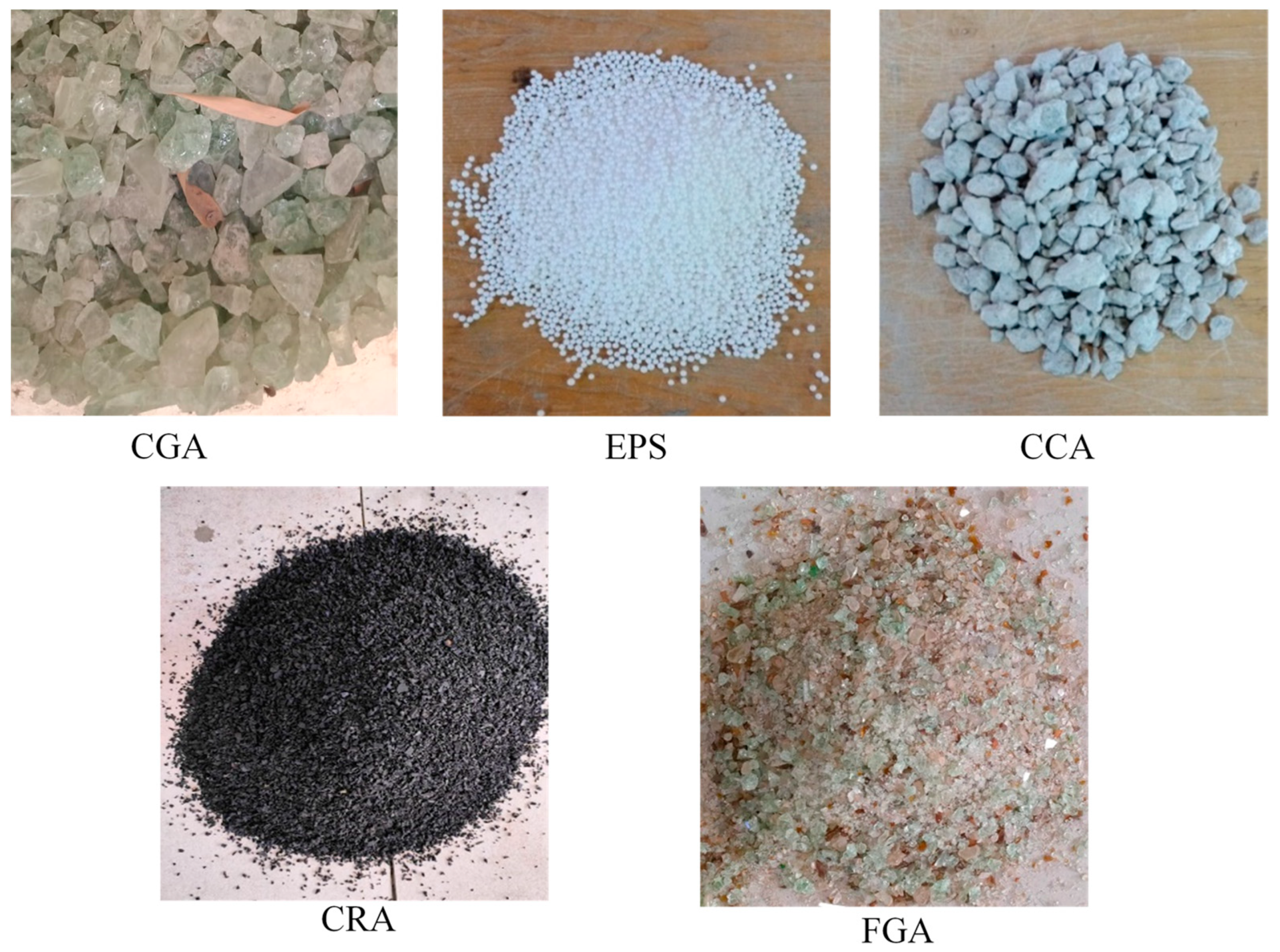
2.1. Material Properties

Stainless steel with a rectangular hollow section: The nominal properties taken from the supplier are equal to 345 MPa, 715.3 MPa, and 212 GPa of yield tensile strength, ultimate tensile strength, and elastic modulus, respectively.
Concrete materials: Three different concrete mixtures were used with various recycled aggregate contents equal to 0% (MC0), 50% (MC50), and 100% (MC100), which were replaced (by volume) with the raw aggregates. A combination of five different recycled aggregates was used to achieve the main objective of this study by adopting the optimum usage of waste materials in the CFSST composite beam system. These recycled aggregates were expanded polystyrene (EPS), crushed concrete aggregate (CCA), and crushed glass aggregate (CGA), which were replaced with raw coarse aggregate. In contrast, crumb rubber aggregate (CRA) and fine glass aggregate (FGA) were replaced with fine raw aggregates, as shown in Figure 1. All recycled aggregates were prepared based on the sieve analysis gradation of the raw aggregates in the concrete mixture. Specifically, in the concrete mixtures with recycled aggregates, 10% of their cement was replaced with silica fume to enhance the motor [45,48]. A 0.5 water: cement ratio (by including 4.0 mL/kg of super-plasticizer liquid type Real Flow 611) was used to improve the concrete mixture’s workability. Three cubes (150 mm) were taken from each concrete mixture, and these were tested after 28 days, as per the standard BS 1881:1983. The concrete proportion mixtures are presented in Table 1.
Adhesive and CFRP sheets: CFRP is a unidirectional sheet type SikaWrap-231 with a 0.13 mm thickness/sheet, 3224 N/mm2 ultimate tensile strength, and 228,800 MPa modulus of elasticity, as per the tensile test carried out earlier in [46]. The adhesive material named Sikadur-330 was used to bond the CFRP sheet to the stainless steel tube surface and the multiple CFRP layers. The nominal physical properties are the same as those adopted previously in [46], that is, 30 MPa and 4.5 GPa for the ultimate tensile strength and modulus of elasticity, respectively.

2.2. Specimen Preparation
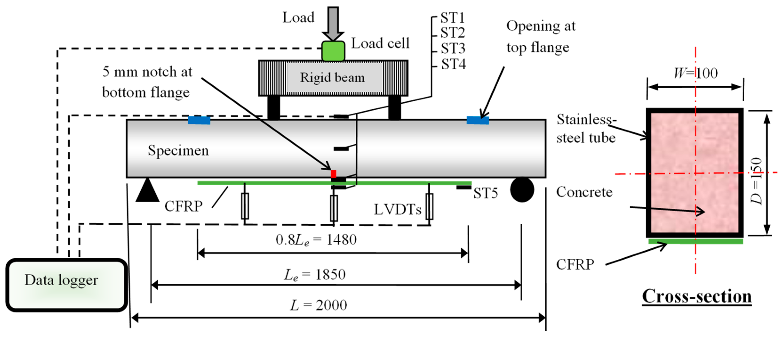
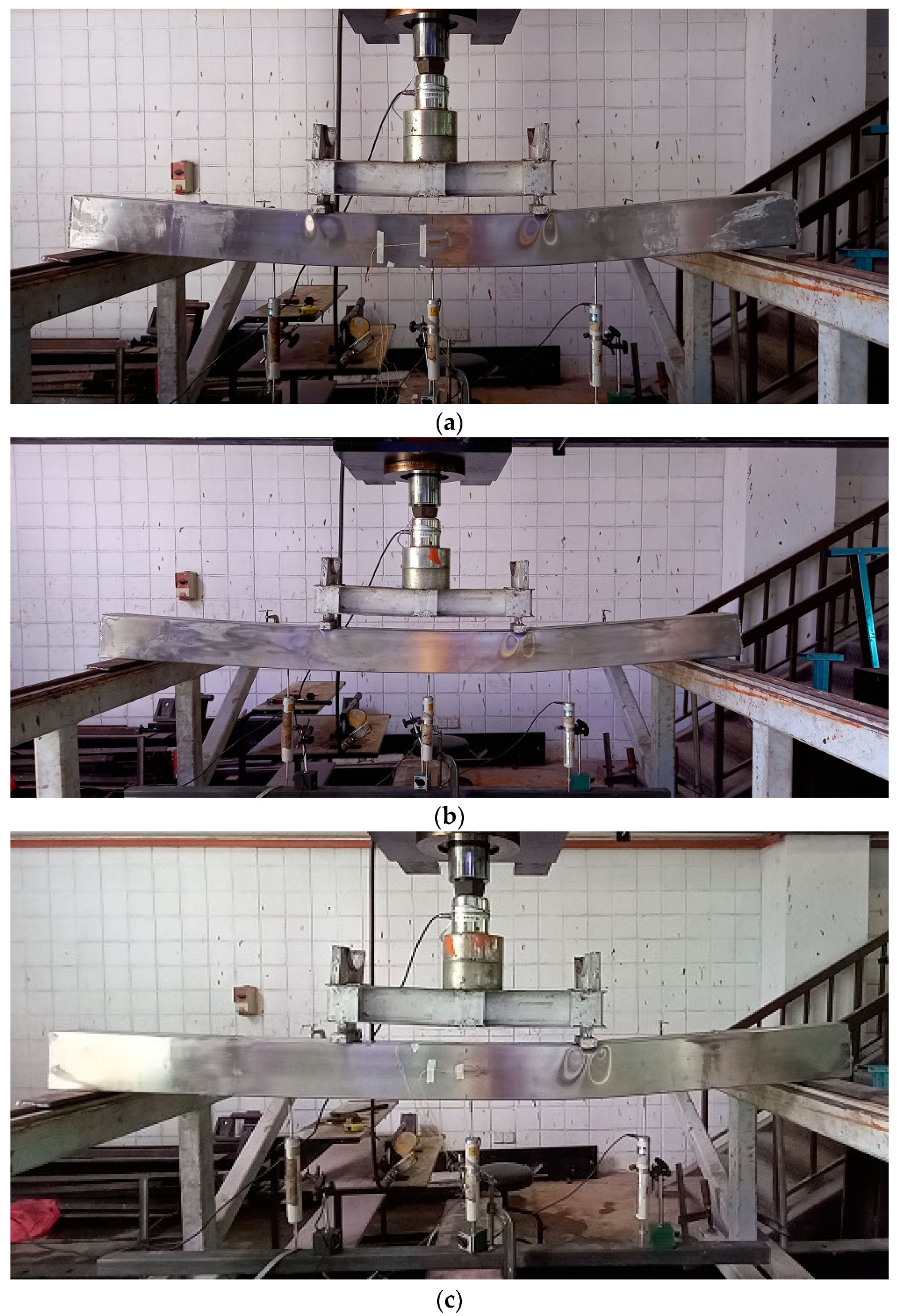
Six rectangular hollow stainless steel sections were filled with concrete material with varied content percentages (of recycled-lightweight aggregates), which were named “RCFSST beams” in this study. In previous similar studies, the concrete was cast inside hollow steel tubes that were placed vertically [45,49]. Whereas, in the current research, to make the process of casting the concrete easier, all stainless steel tubes were placed horizontally with two rectangular openings (50 mm × 75 mm) at their top flanges, as shown in Figure 2. These openings are located within the shear span distance (between the point loads and supports). Both ends of the tubes were closed temporarily during the casting of the concrete, which was poured in sequence from these openings. An electrical vibrator was used to distribute the concrete inside the tubes homogenously. Generally, fully filling the stainless steel tube with concrete is not expected, specifically when these tubes are placed horizontally and the concrete is poured through these openings; small gaps (concrete imperfection) are still acceptable, since these have minor effects on the concrete-filled steel tube’s capacity, as earlier proven by Liao et al. [50].
Three concrete mixtures that contained a combination of varied percentages of recycled aggregates were used. One stainless steel tube specimen was filled with normal concrete material (0% of recycled aggregates), and was named “MC0”. Another specimen was filled with concrete material with a content of 50% recycled aggregates, and it was named “MC50”, and the rest of the specimens were filled with a concrete material content of 100% recycled aggregates, and were named “MC100”. In addition, the study investigated the repairing performance of the RCFSST specimens using CFRP sheets, specifically for those specimens with the highest content of recycled aggregates (MC100). Prior to applying the CFRP sheets, a small notch was made at the bottom flange (5 mm-wide cutting) of the three RCFSST specimens to simulate the damage that could happen in this type of composite beam [46]. One notched RCFSST specimen was kept without being strengthened, while the other two specimens were strengthened with one and three CFRP layers, which were named MC100-N, MC100-N-1CFRP, and MC100-N-3CFRP, respectively, as presented in Table 2. For the optimum usage of the CFRP sheets to strengthen the RCFSST specimens, these sheets were applied along 80% of the specimen’s effective span (bottom flange only) by using the same concept and application process that was adopted for the CFST beams [45].

2.3. Test Setup

The prepared RCFSST specimens were tested under pure bending (four-point loading) in the lab at Universiti Kebangsaan Malaysia (UKM) using a hydraulic jack with 500 kN loading capacity, as shown in the test setup in Figure 3. The load was gradually applied at an average rate of 4–6 kN/minute. Linear variable differential transducers (LVDTs) were used for measuring the deflection values at the midspan and quarter-length of the specimen’s span. In addition, five strain gauges (ST1–ST5) were provided at different locations for measuring the longitudinal tensile strain at the outer surfaces of the stainless steel tube and CFRP patch (see Figure 3). The data logging device was connected to a PC for collecting and recording the data during the test.

3. Results Discussion
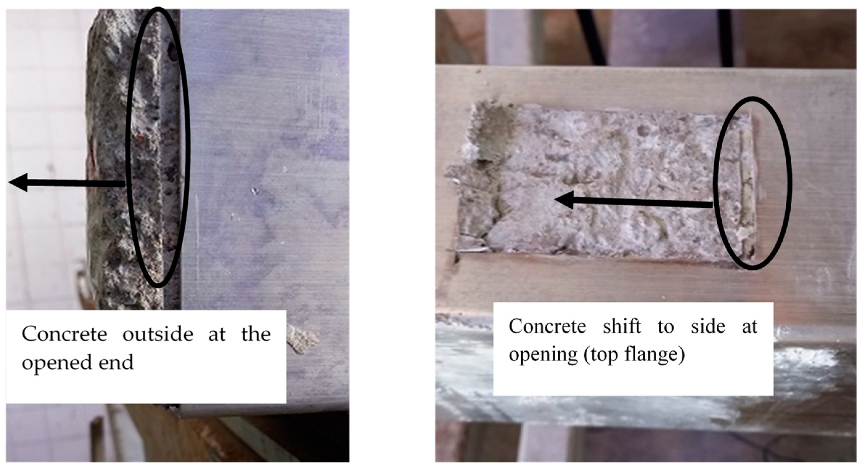
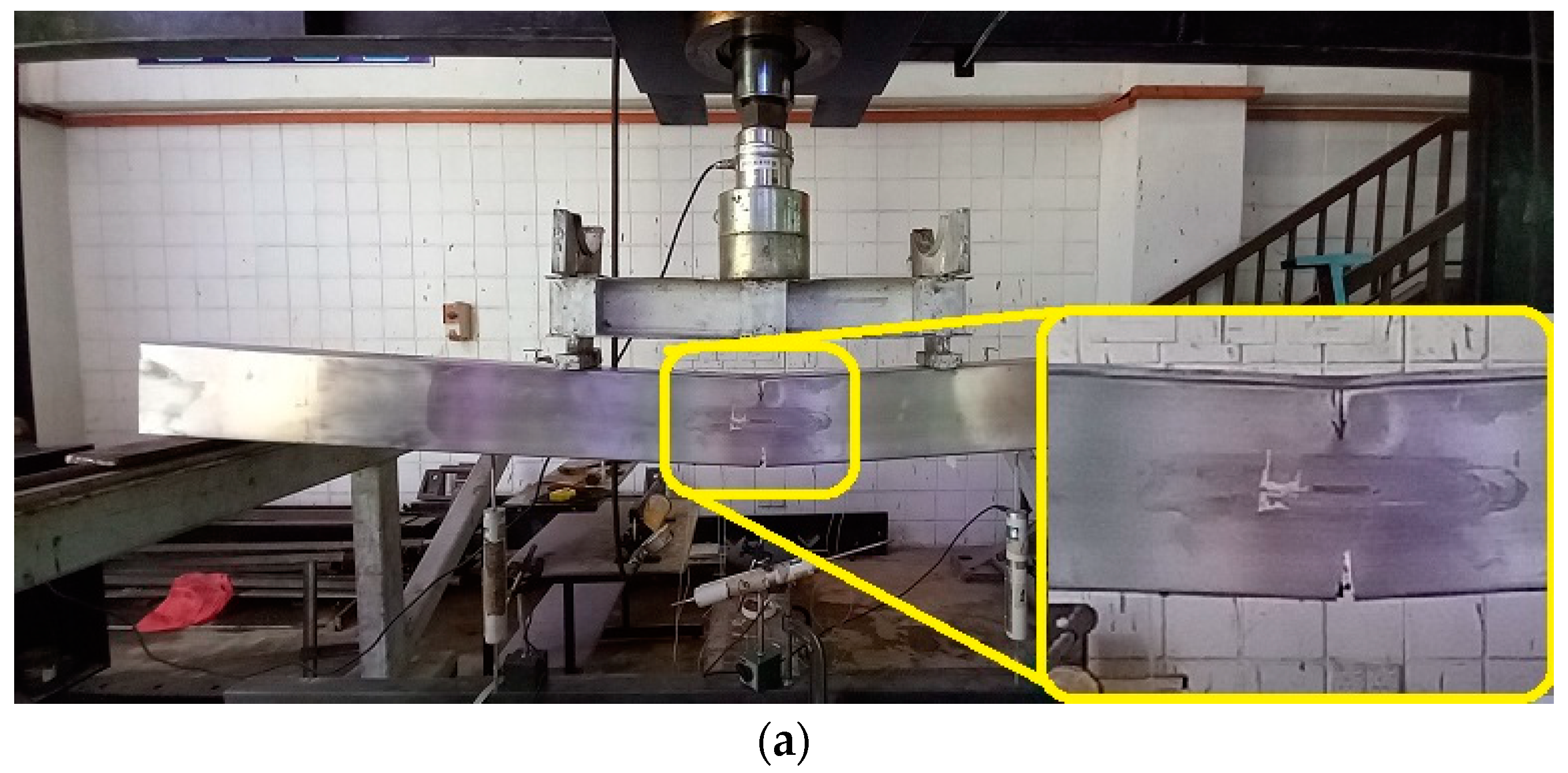
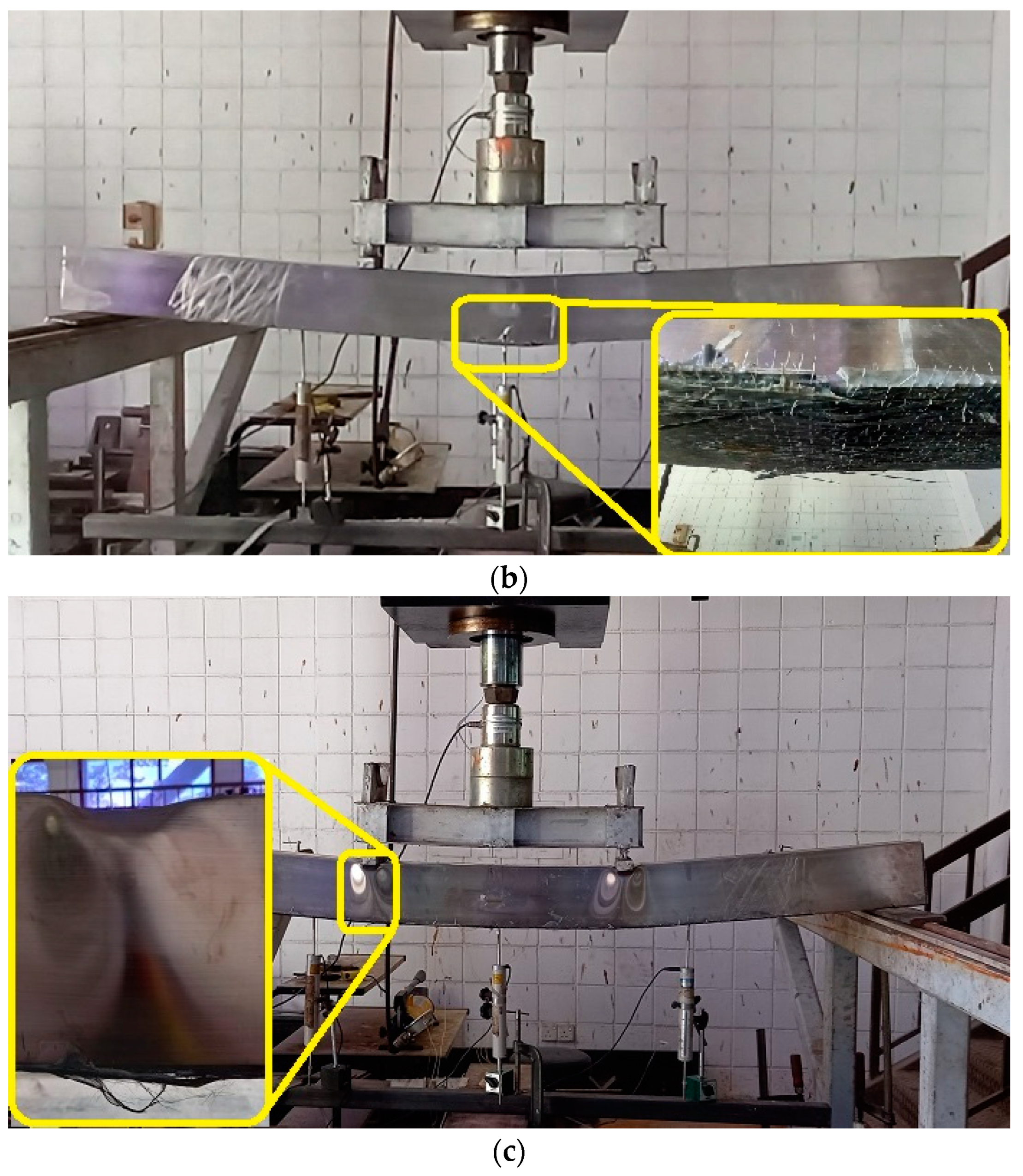
3.1. Failure Modes

3.1.1. RCFSST Specimens with Varied Recycled Aggregates

All specimens were tested beyond their ultimate capacities to further understand the extreme flexural behavior of this composite beam system. The specimens MC0, MC50, and MC100 showed typical flexural behaviors regardless of the aggregate replacement percentages, as shown in Figure 4. The specimens deflected smoothly until the applied load achieved about 85–90% of their ultimate capacities. Then, an outward tube buckle was created, specifically under the point loads, which is reasonable behavior for the pure CFST beams [45,49,51].
Generally, infill concrete materials are usually made to delay/prevent the inward local buckling of the steel tube beams regardless of the infill concrete compressive strength value, while the bending capacity of the concrete-filled steel tube beams is slightly affected due to the compressive strength value [3,29,49]. Based on this, the infill concrete materials with 0% and 100% recycled aggregate contents showed similar failure modes inside the stainless steel tube; both were cracked at the bottom fibers when subjected to high tension stress (the distance between the two point-loads) and were crushed at the top fibers when subjected to high compression stress, as shown in Figure 5. However, exactly underneath the point loads, the specimens with 100% recycled aggregate replacement (MC100) showed more damage behavior than the specimen filled with normal concrete (MC0). This is because of the low compressive strength of the concrete material with 100% recycled aggregate content (see Table 1). This type of failure (buckling under direct point loads) will not occur and/or could be avoided when these RCFSST beams are used in a conventional floor system, since they will be subjected to a uniform distributed load. In addition, even when used carefully, the vibrator, while casting the concrete, created a small gap between the tube’s top flange and the concrete core (see Figure 5); this small gap is expected to have very limited effect on the bending capacity of this composite beam system [50].
Generally, the provided openings at the top flanges of the stainless steel tubes showed no side effects on the flexural behavior of all of the tested RCFSST specimens. However, after passing the ultimate loading capacity of these specimens (at the extreme failure mode), a part of the concrete core split exactly underneath one of the point loads (see Figure 5). This concrete portion moved sideways slightly to the nearest end of the specimen, as shown in Figure 6. This type of failure can be avoided when the ends of these tubes are permanently plugged (covered).

3.1.2. RCFSST Specimens Strengthened with CFRP Sheets

The notched (pre-damaged) RCFSST specimens, including those strengthened with one or three CFRP sheets, are presented in Figure 7. The stainless steel tube of the MC100-N specimen suddenly fractured under a certain load limit, specifically from the notch (cut) that was created on the bottom flange (midspan). The corresponding specimens strengthened with one CFRP layer (MC100-N-1CFRP) showed better flexural behavior, whereby the specimen resisted the applied load until the CFRP sheet ruptured at the midspan once it achieved its ultimate tensile strength. However, the specimens strengthened with three CFRP layers (MC100-N-3CFRP) showed much greater flexural strength than the above specimens, since the related CFRP patch did not fracture until the strengthened specimen achieved its ultimate bending capacity; instead, the tube’s top flange started to buckle under the point load (see Figure 7c). Generally, along the bonding surfaces between the stainless steel tube (bottom-flange) and CFRP patch, an intermediate debonding failure probably occurred at the mid-span distance (high-tensile stress zone). However, the CFRP patch continued to resist the peeling stress at both ends, since they were located near the beam’s supports, and the bending stresses at this distance were very minimum compared to that at mid-span. Thus, the CFRP patch was not debonded from the beam, and that led to improving the beam’s bending capacity until it reached the patch’s ultimate tensile strength [45,46]. All of the tested RCFSST specimens with/without CFRP sheets were similarly deflected to the half-sine curve, especially at the loading stages below 90% of their bending capacities (0.9 Mu), as shown in Figure 8.

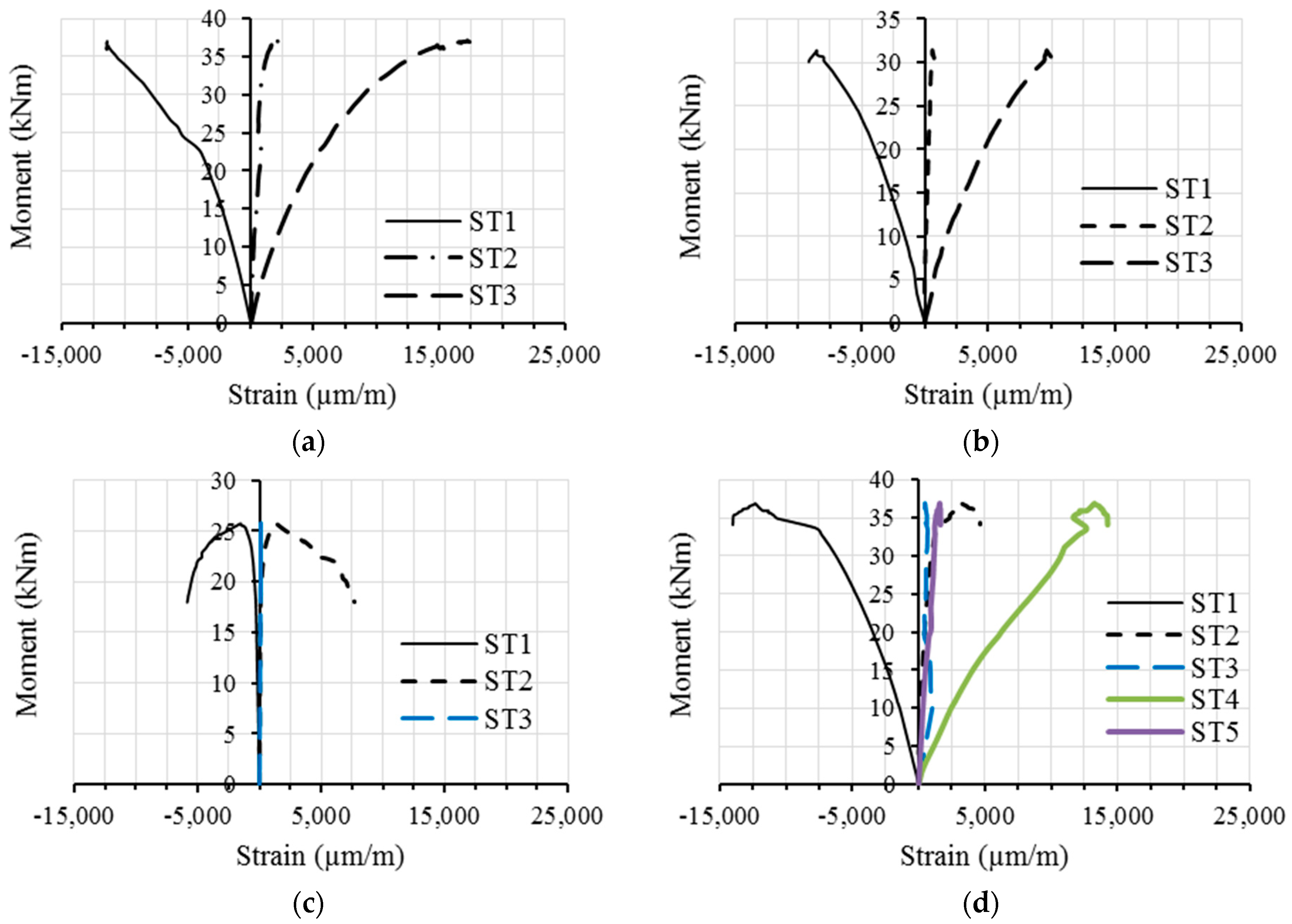
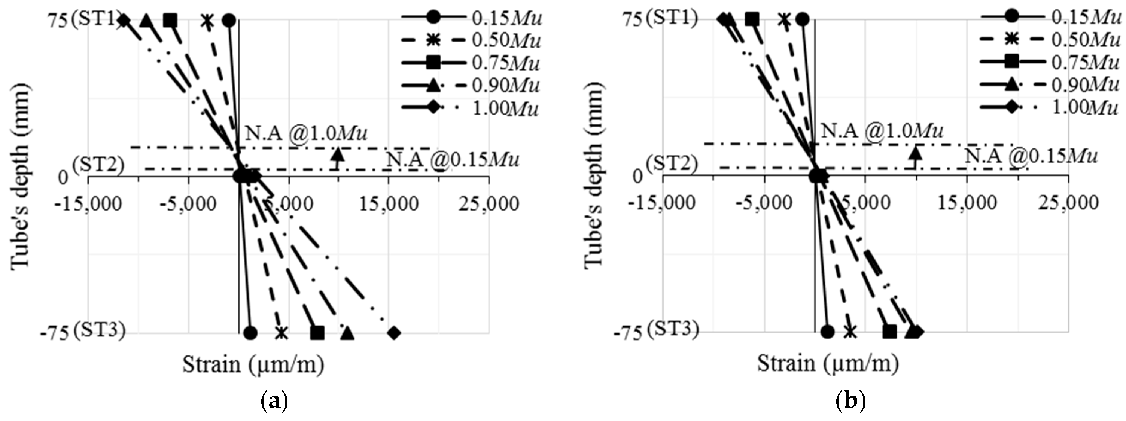
3.2. Bending Moment versus Tensile Strain

The moment–strain relationship of the tested RCFSST specimens is shown in Figure 9. When using concrete infill materials with varied recycled aggregate contents, there were no side effects on the moment–strain relationships of the RCFSST specimens. For both specimens, the negative strain values (due to compression stress) at the top flanges (ST1) and the positive values (due to tension stress) at the bottom flanges (ST3) increased gradually with an increase in bending moment. Meanwhile, the ST2 showed slight increases in the positive values (tension stress), confirming the upward movement of the neutral axes from the center of the tubes’ cross-section [46]. The moment–strain relationships of the pre-damaged RCFSST specimens before and after strengthening with the three CFRP sheets are presented in Figure 9c,d. The highest tension strain value was recorded at the midspan of the CFRP surface (ST4) of specimen MC100-N-3 CFRP, since it was located at the maximum tensile stress (distance between the two-point loads). In contrast, the tensile strain value at the end of the CFRP patch (ST5) showed a very limited increase in value up until the end of the test, confirming the absence of much peeling stress (see Figure 3). Furthermore, typical tensile strain distribution behavior was recorded along the depth of the RCFSST beam’s cross-section for both the MC0 and MC100 specimens, as shown in Figure 10, which is similar to those previously tested in the CFST beams [45,52].

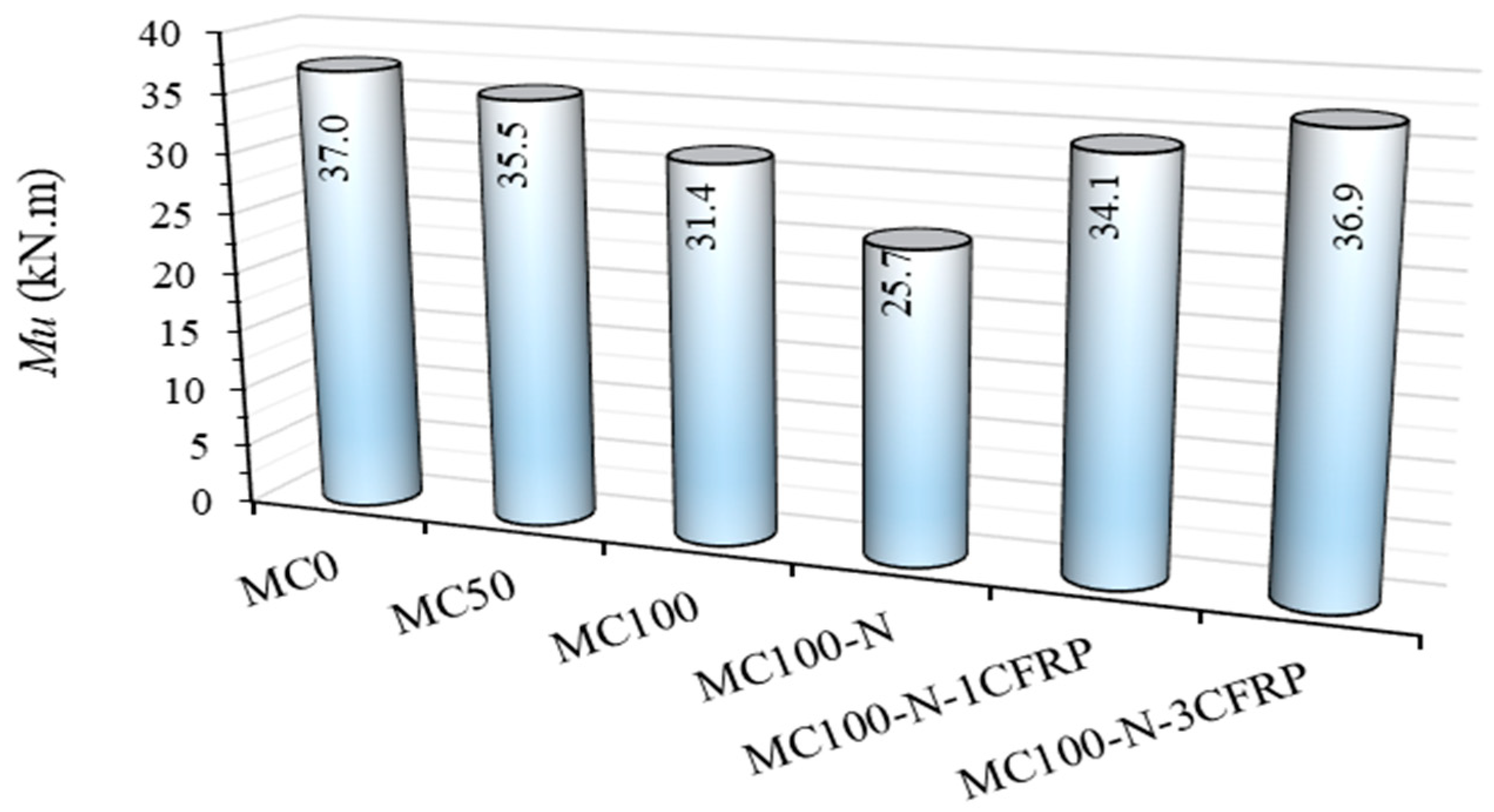
3.3. Bending Moment Capacity

The flexural behavior of the tested RCFSST specimens with varied recycled aggregate contents is presented in Figure 11. The ultimate bending capacity (Mu) was recorded at the peak value and/or at a deflection limit equal to Le/50Le/60 (whichever was achieved first) [45]. Generally, the moment–deflection curves showed a linear behavior at the initial loading stage (up to 0.5–0.6 Mu). Then, the curve behaved as an elastoplastic, which continued until the buckling failure started at the tube’s top flange at a loading stage of about 0.85–0.9Mu. Then, the plastic behavior was recorded for the moment–deflection curves until the bending moment capacity was achieved. Beyond the Mu value, the moment–deflection curve dropped gradually as the tube’s buckling failure increased and the concrete core started to crush under the point loads. In general, the stainless steel tube beams showed a flexural performance similar to that of the carbon/cold-formed steel tube when filled with recycled concrete materials [31,32,45,51].
Similar behavior was exhibited by the RCFSST specimens strengthened with the CFRP sheets, as shown in Figure 12. The CFRP sheets started to crack at a loading stage of 0.9 Mu to 0.95 Mu; the Mu value was recorded at the point when the CFRP sheet ruptured (once it achieved its tensile capacity), since no CFRP delamination failure occurred. Then, the bending curve dropped rapidly due to the absence of CFRP strength. Figure 13 compares the ultimate bending moment values achieved by the tested RCFSST specimens. The Mu value decreased continuously with the increase in the recycled aggregates, which is logical behavior since the concrete strength of the infill material decreased accordingly (see Table 2). Specimen MC0 (0% of recycled aggregates) achieved a Mu value of 37.0 kN·m, which decreased to 35.5 kN·m (−4.2%) when using 50% recycled aggregates in infill concrete materials (specimen MC50). Then, the same Mu value of the control specimen was further decreased to 31.4 kN·m (−15%) when using 100% recycled aggregates (specimen MC100). The pre-damaged RCFSST specimen MC100-N achieved a Mu value of 25.7 kN·m, which is about 18% lower than that of the corresponding MC100 specimen. However, this value was sufficiently enhanced when strengthened with one layer of CFRP sheeting (34.1 kN·m). It was further enhanced when strengthened with three CFRP layers (36.9 kN·m), which is about 17.6% higher than the corresponding undamaged specimen (MC100).

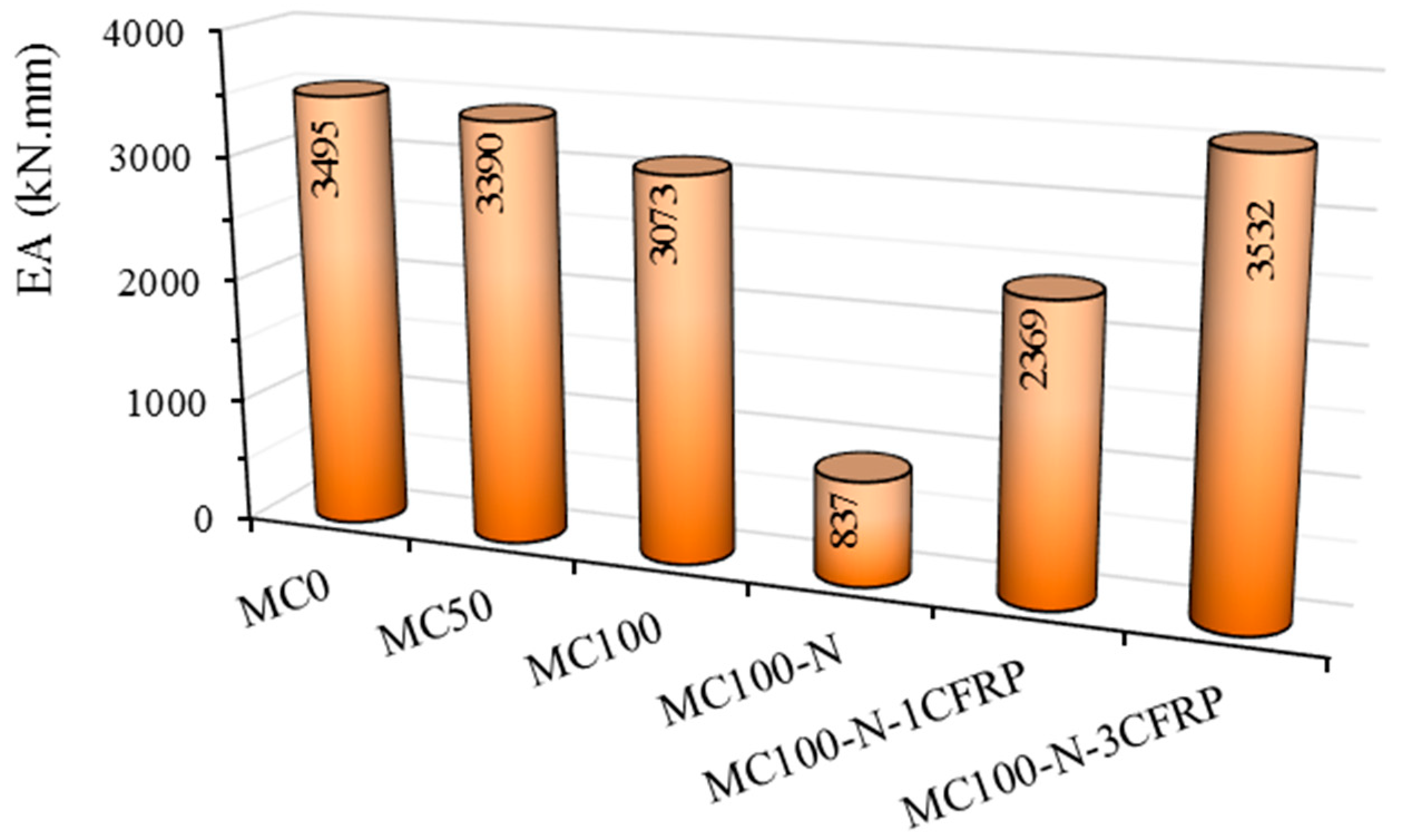
3.4. Energy Absorption (EA) Index

The RCFSST specimen’s ability to absorb energy under a static bending load can be predicted from the load–deflection curves [49,53,54]. The EA values of the tested specimens are compared in Figure 14. The comparison established that there is a reduction in the RCFSST specimen’s EA index with an increase in recycled aggregates, which is logical behavior, since the related loading curve reduced accordingly (see Figure 11). For example, the control specimen MC0 achieved an EA value of 3495 kN·mm, which was reduced by about 3% (3390 kN·mm) when 50% recycled aggregates (MC50) were used in the concrete core. Then, it was further reduced by about 12% (3073 kN·mm) when 100% recycled aggregates were used (MC100). Furthermore, the EA index of the RCFSST specimens improved a lot when strengthened with the CFRP sheets (MC100-N-1CFRP and MC100-N-3CFRP) when compared to the corresponding damaged specimen MC100-N. Again, this is due to the improvement in the loading–deflection relationship when multiple CFRP sheets are adopted for strengthening the RCFSST specimen (see the earlier comparison in Figure 12).

4. Numerical Method

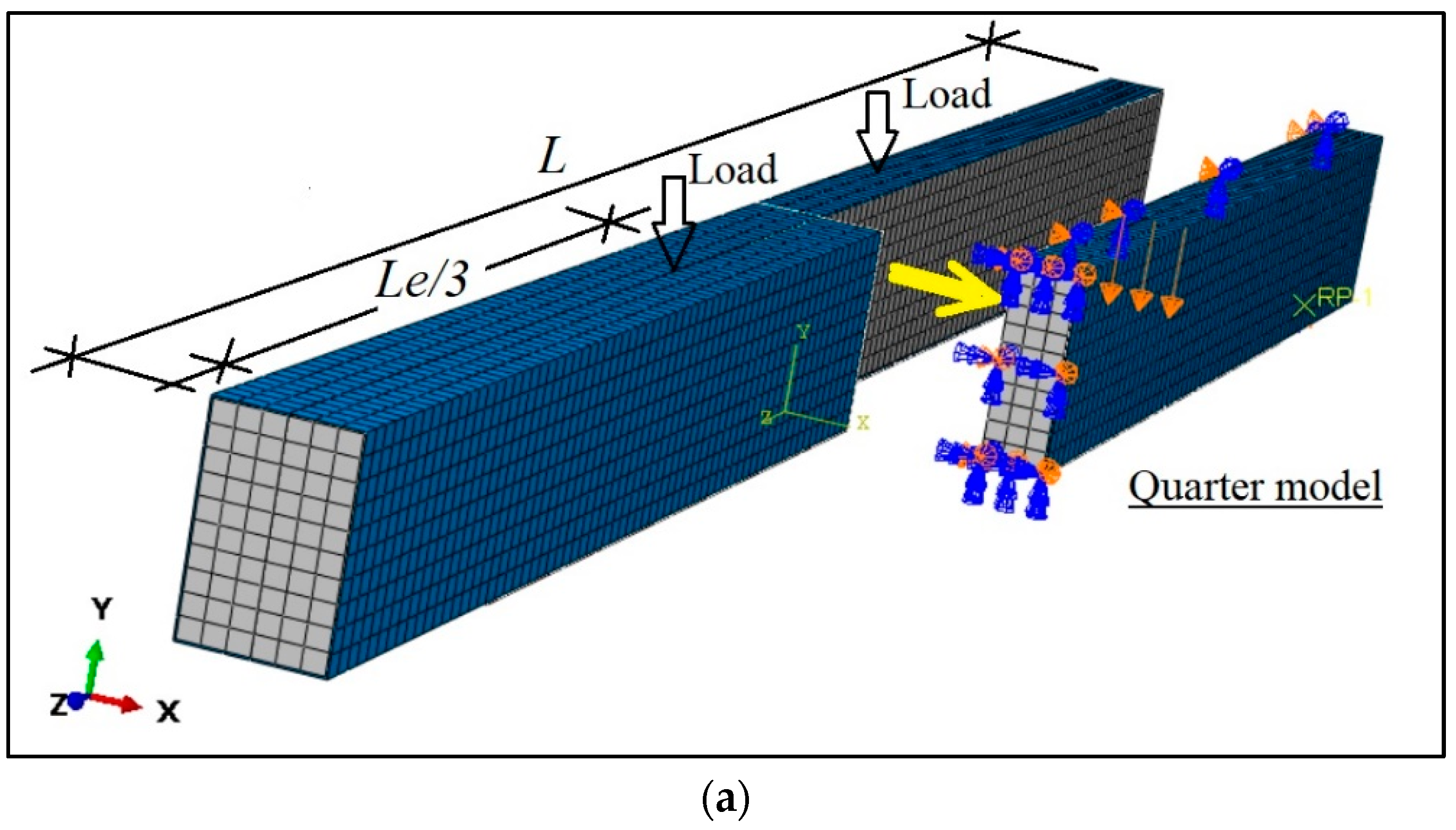
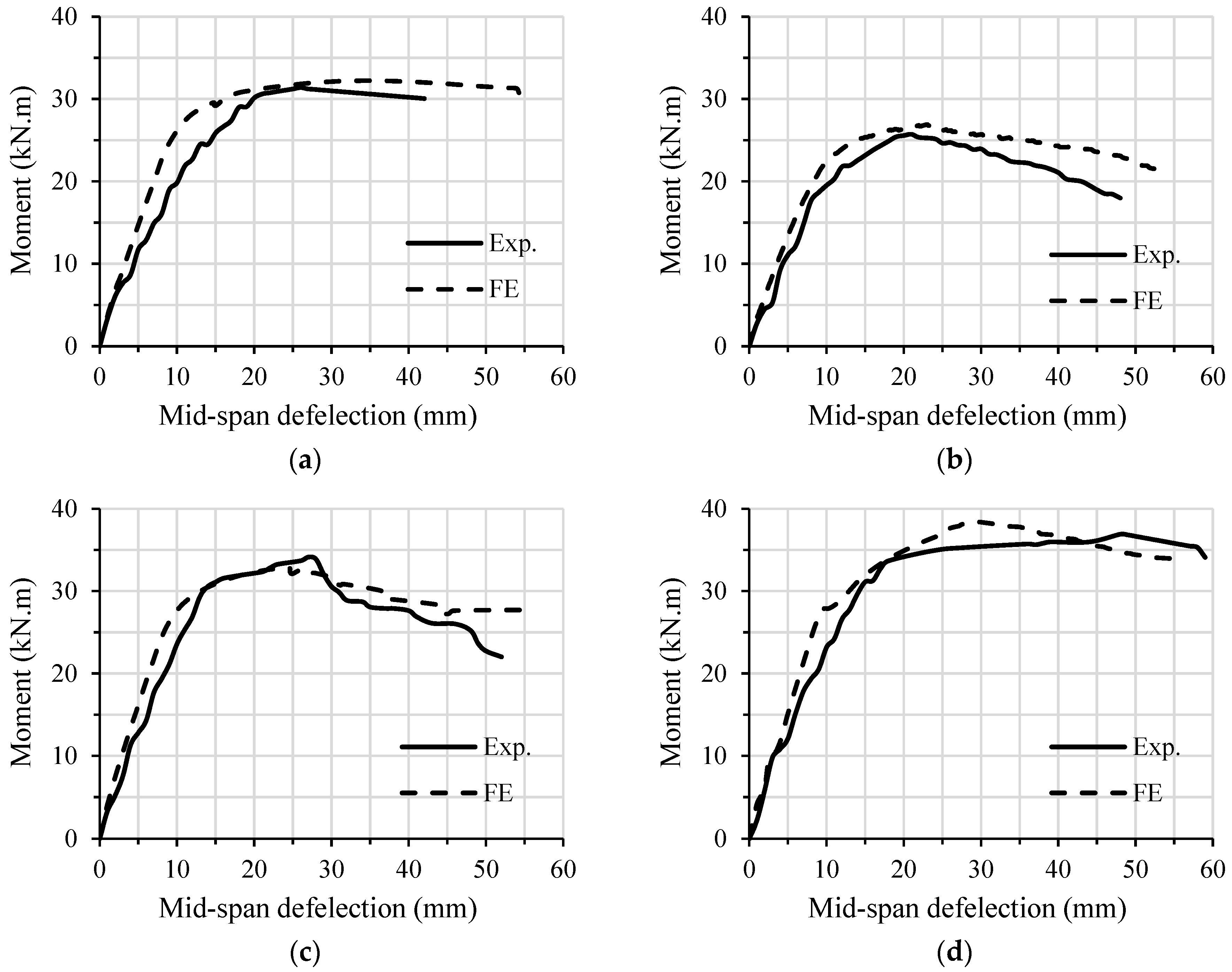
4.1. Finite Element (FE) Modeling

In this study, ABAQUS software was used for modeling the RCFSST beams with/without the CFRP sheets. The typical 3D quarter FE model was built and analyzed using the same boundary conditions, loading scenario, and material properties (stainless steel, concrete, and CFRP) that were adopted in the current experimental approach, as shown in Figure 15. In general, this numerical approach used the same modeling concept adopted in similar FE analysis studies [45,55,56]. The downward displacement option was used at the location of the point loads to simulate the actual testing load of the RCFSST specimens, where the reaction values at the supports were accumulated to estimate the total applied load. For the RCFSST model strengthened with CFRP sheeting, the FE analysis was continued until the ultimate tensile strength of the CFRP patch had been achieved. Furthermore, for modeling the concrete core of the RCFSST beams, the C3D8R-type element was used, whereas, for both the stainless steel tube and CFRP patch, the S4R-type element was used. A full tie interaction option was used for implementing the contacted surface between the CFRP patch and the stainless steel tube (at the bottom flange of the RCFSST model), since no debonding failure occurred. A friction coefficient equal to 0.7 was used for employing the contact behavior between the stainless steel tube and the concrete core.
The same material properties of the tested RCFSST specimens were used for the corresponding FE models. The core concrete was identified in the FE model as an isotropic material, since it can be cracked under tension stress and crushed under compression stress; thus, the option named concrete damage plasticity was used [45,46,55]. Lastly, the properties of the CFRP sheet were identified using the Hashin damage to simulate the actual tensile damage mechanism, since it is considered an orthotropic linear elastic material. In addition, the adhesive material was not identified as an independent part in the FE model, where the adhesive layer between the tube’s surface and the first CFRP sheet is considered fully bonded (full tie interaction at the bottom flange). The CFRP patch technique was used to implement the multiple CFRP sheets and the adhesive layers in between [45,46]. Based on that, the same constitutive stress–strain relationships of these materials (concrete, steel, and CFRP) that were used earlier in [45,46] were adopted for the suggested RCFSST models.
The tested pre-damaged RCFSST specimens with 100% recycled aggregate and strengthened with CFRP sheets have been chosen to validate the suggested modeling method. The flexural behavior and bending strength of the currently analyzed FE models agreed well with those obtained for the corresponding tested specimens, as compared in Figure 16. However, the gap between the load–deflection curves of these two methods is probably related to the experimental test, since it was carried out using a manual hydraulic jack, while the FE models were analyzed idealistically. Furthermore, these FE models reasonably simulated the actual failure mode of the tested specimens, as shown in Figure 17.

4.2. Effects of the Varying Parameters

This section presents further numerical analyses of the RCFSST models (100% recycled aggregates content) with/without CFRP sheets to further examine the parameters that have not yet been studied and/or tested. Specifically, the effects of the varied width-to-thickness (w/t) ratios (15 to 48) and tensile yielding strengths (345 MPa, 395 MPa, and 451 MPa) were analyzed. By increasing the stainless steel tube’s thickness, this means that, as the tube’s section starts to become more compact, the Mu value of the RCFSST model increases accordingly. For example, increasing the tube’s thickness from 2 mm (w/t = 48; slender cross-section) to 6 mm (w/t = 15; compact cross-section) led to an increase in the Mu value by about 2.42 times (23.3 kN·m to 56.4 kN·m), as shown in Figure 18a. Furthermore, the same models with varied tube thicknesses showed a reasonable response when strengthened with three CFRP layers. In addition, the same behavior was recorded when using stainless steel tubes with a higher tensile strength, but with fewer improvement percentages, as shown in Figure 18b. Based on the FE analysis results, it can be concluded that stainless steel tube beams behave in a similar fashion to carbon steel tube beams when filled with recycled concrete materials [45,52].

5. Analytical Design Guidelines

The ultimate bending capacity (Mu) values of the currently tested and analyzed RCFSST beams were verified with the corresponding predicted values using the well-known theoretical standards and methods in this field. These methods are the Eurocode 4 (2004) [57], Han (2004) [58], and Al Zand et. al. (2020) [59] methods for estimating the bending capacity of the CFST beams, and the method developed by Al Zand et al. (2018) [46] for the CFST beams strengthened with CFRP sheets. The expressions of these methods are as follows:
EC4—2004 [57]
Mu-EC4 = (WpaWpanfy + 0.5·(WpcWpcnfck
Wpc = 0.25·(W − 2·t)·(D − 2·t)2 − 2/3·r3r2·(4 − π)·(0.5·Dtr)
Wpcn = (W − 2·thn2
Wpa = 0.25·B·D2 − 2/3·(r + t)3 − (r + t)2·(4 − π)·(0.5.Dtr) − Wpc
Wpan = W·hn2Wpcn
hn = (Ac·fck)/((2·D·fck) + 4·t·(2·fyfck))
Han—2004 [58]
Mu-Han = γm·Wscm·fscy
γm = 1.04 + 0.48ln(ξ + 0.1)
fscy = (1.18 + 0.85·ξfck
Wscm = W.D2/6
Al Zand et al.—2020 [59]
Mu-P2 = β2·fcu·Zcomp
Zcomp = Is/(D/2) + Ic/(D/2 − t)
β2 = 0.51 [ln(ξ + 0.95)]2 + 2.2·ln(ξ + 0.95) + 0.1
Al Zand et al.—2018 [46]
Mu-P = γ·Wscm·fscy
Wscm = B·D2/6
γ = 0.6ln(ξ + ξccf) + 1.0
fscy = (1.18 + 0.85·(ξ + ξscf))·fck
ξccf = (Acfp·fcfp)/(Ac·fck)
ξscf = (Acfp·fcfp)/(As·fy)
tcfp = (n·tcfp.sheet) + tad·(n − 1)
Acfp = tcfp·W
fcfp = [(n·tcf.sheet·fcfp.sheet) + tad·(n − 1)·fad]/tcfp
The obtained Mu values of the RCFSST specimens and models are compared to the corresponding predicted values in Figure 19, including those strengthened with the CFRP sheets (see Figure 19d). Generally, these methods showed reasonably lower estimations of the obtained results, where they achieved mean values (MVs) ranging from 0.816 to 0.937, with sufficient standard deviations (SDs) ranging from 0.015 to 0.082, for all of the mentioned methods. This comparison confirmed the validity of the currently investigated RCFSST beams and models with/without the effects of CFRP sheeting.

6. Conclusions

The following conclusions are summarized from the analyses of the results:
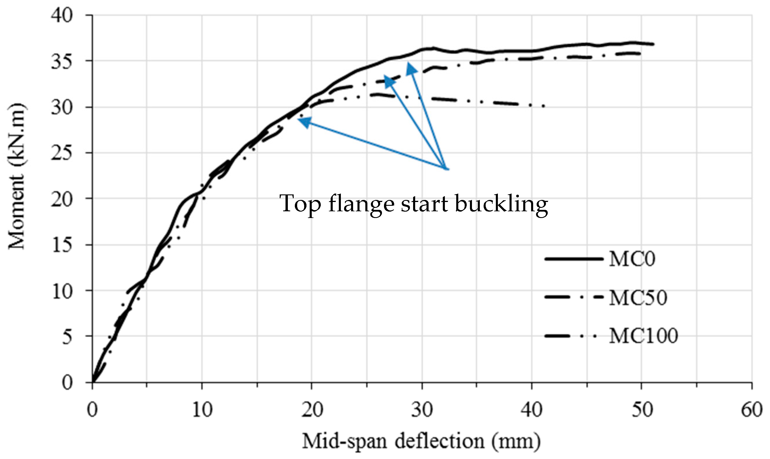
  • The concrete-filled stainless steel tube beams showed a flexural behavior and failure mode very similar to those previously tested using carbon steel tubes, particularly when using a combination of varied lightweight, recycled aggregates (EPS, CCA, CGA, CRA, and FGA). By using up to 100% recycled aggregate content, the concrete infill strength and weight of the RCFSST beam were reduced by about 25% and 12%, respectively, while the bending capacity of these beams was reduced by about 15% compared to the corresponding beam filed with normal concrete;
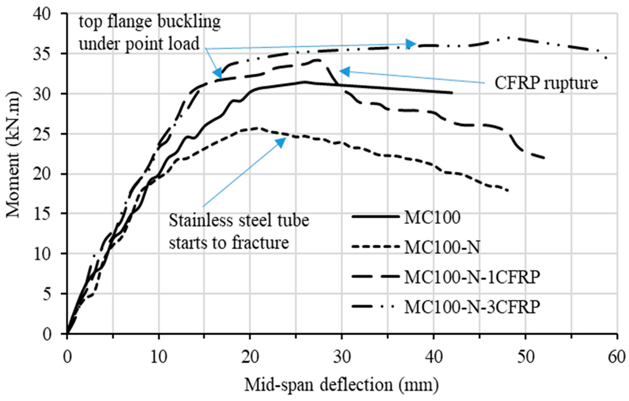
  • The flexural performance of the pre-damaged RCFSST beams was extensively improved when strengthened the bottom flange only with CFRP sheets. The flexural strength capacity of the pre-damaged RCFSST beams was improved by about 32.7% and 43.6% when strengthened with one and three CFRP layers, respectively;
  • The energy absorption index of the RCFSST beams was reduced by about 35% and 12% when the content of the lightweight, recycled aggregates in the concrete core was increased by about 50% and 100%, respectively;
  • The FE models have reasonably simulated the actual bending behavior of the tested RCFSST specimens. Generally, increasing the w/t ratio showed a higher bending enhancement for the beams strengthened with multiple CFRP layers, which is very similar to the behavior of previously investigated CFST beams (carbon/cold-formed steel tube). For example, the RCFSST models with w/t ratios equal to 15 and 48 achieved a bending capacity improvement equal to 18% and 35%, respectively, when strengthened with three CFRP layers. Furthermore, the predicted Mu values of the tested specimens and analyzed models using the existing methods confirmed the validity of the current investigations with acceptable deviations ranging from 0.015 to 0.082;
  • The strengthening and repairing performance of the CFSST beams using CFRP sheets still needs more investigation by considering the effects of varied parameters that have not yet been studied, such as different beam cross-sections and wrapping schemes under different loading scenarios (cyclic/fatigue).

Author Contributions

Conceptualization, N.M.R.D., A.W.A.Z., M.C.L. and W.H.W.B.; Data curation, N.M.R.D., M.C.L. and M.A.; Formal analysis, N.M.R.D. and M.C.L.; Funding acquisition, A.W.A.Z., W.M.T. and A.B.M.A.K.; Investigation, N.M.R.D., M.C.L. and M.A.; Methodology, A.W.A.Z. and W.H.W.B.; Project administration, W.H.W.B. and A.B.M.A.K.; Validation, W.M.T., M.A. and Z.M.Y.; Resources, A.W.A.Z. and Z.M.Y.; Software, A.W.A.Z. and M.A.; Supervision, A.W.A.Z., W.H.W.B. and A.B.M.A.K.; Visualization, W.M.T. and Z.M.Y.; Writing—original draft, N.M.R.D., A.W.A.Z., M.C.L. and M.A.; Writing—review & editing, W.H.W.B., A.B.M.A.K., W.M.T. and Z.M.Y. All authors have read and agreed to the published version of the manuscript.

Funding

The authors are grateful for the research grant provided by the Ministry of Higher Education, Malaysia, through the Fundamental Research Grant Scheme (Number: FRGS/1/2019/TK06/UKM/01/1).

Data Availability Statement

Data are presented in the article.

Acknowledgments

The authors highly acknowledge their Institutes and Universities for the support to prepare and complete this research.

Conflicts of Interest

The authors declare no conflict of interest.

Abbreviations

Area of concrete core cross-section (Ac); area of CFRP patch cross-section (Acfp); area of steel tube cross-section (As); depth of rectangular steel tube (D); ultimate tensile stress of adhesive material (fad); compression stress of concrete at relevant strain (ε) value (f); ultimate tensile stress of CFRP sheet (fcfp.sheet); ultimate tensile stress of CFRP patch (fcfp); concrete cylinder compressive strength at 28 days (fc); concrete cube compressive strength at 28 days (fcu); characteristic concrete strength (fck = 0.67fcu); stress of concrete at cracking failure (fcr); yield strength of the composite section (fscy); tensile stress of concrete at relevant strain (εt) value, (ft); ultimate strength of steel (fu); yield strength of steel (fy); bending moment (M); ultimate bending moment (flexural bending capacity, Mu); number of CFRP layers (n); wall thickness of steel tube (t); thickness of adhesive layer (tad); thickness of CFRP sheet (tcfp.sheet); thickness of CFRP patch (tcfp); width of rectangular steel tube (W); effective width of tube to thickness ratio (w/t); section modulus for the rectangular tube sections (Wscm); strain at relevant concrete compression stress (f) value (ε); steel confinement factor ξ = (As·fy)/(Ac·fck).

References

  1. Feng, R.; Chen, Y.; Wei, J.; Huang, J.; Huang, J.; He, K. Experimental and Numerical Investigations on Flexural Behaviour of CFRP Reinforced Concrete-Filled Stainless Steel CHS Tubes. Eng. Struct. 2018, 156, 305–321. [Google Scholar] [CrossRef]
  2. Liao, F.-Y.; Han, L.-H.; Tao, Z.; Rasmussen, K.J.R. Experimental Behavior of Concrete-Filled Stainless Steel Tubular Columns under Cyclic Lateral Loading. J. Struct. Eng. 2017, 143, 04016219. [Google Scholar] [CrossRef]
  3. Han, L.H.; Xu, C.Y.; Tao, Z. Performance of Concrete Filled Stainless Steel Tubular (CFSST) Columns and Joints: Summary of Recent Research. J. Constr. Steel Res. 2019, 152, 117–131. [Google Scholar] [CrossRef]
  4. Dabbagh, N.M.R.; Wan Badaruzzaman, W.H.; Al Zand, A.W.; Kazemzadeh Azad, S.; Uy, B.; Azmi, M.R.; Alatshan, F. A Systematic Review on CFST Members under Impulsive Loading. Thin-Walled Struct. 2022, 179, 109503. [Google Scholar] [CrossRef]
  5. Kazemzadeh Azad, S.; Li, D.; Uy, B. Compact and Slender Box Concrete-Filled Stainless Steel Tubes under Compression, Bending, and Combined Loading. J. Constr. Steel Res. 2021, 184, 106813. [Google Scholar] [CrossRef]
  6. Yan, X.F.; Hassanein, M.F.; Wang, F.; He, M.N. Behaviour and Design of High-Strength Concrete-Filled Rectangular Ferritic Stainless Steel Tubular (CFFSST) Short Columns Subjected to Axial Compression. Eng. Struct. 2021, 242, 112611. [Google Scholar] [CrossRef]
  7. Uy, B.; Tao, Z.; Han, L.H. Behaviour of Short and Slender Concrete-Filled Stainless Steel Tubular Columns. J. Constr. Steel Res. 2011, 67, 360–378. [Google Scholar] [CrossRef]
  8. Kadhim, M.M. Numerical Modelling of Concrete-Filled Stainless Steel Slender Columns Loaded Eccentrically. World J. Eng. 2020, 17, 697–707. [Google Scholar] [CrossRef]
  9. Gunawardena, Y.; Aslani, F. Concrete-Filled Spiral-Welded Stainless-Steel Tube Long Columns under Concentric and Eccentric Axial Compression Loading. J. Constr. Steel Res. 2019, 161, 201–226. [Google Scholar] [CrossRef]
  10. Ye, Y.; Yao, X.H.; Guo, Z.X. Performance of Concrete-Filled Stainless Steel Tubes Subjected to Concentric Tension: Numerical Investigation and Parametric Study. Structures 2021, 32, 2222–2231. [Google Scholar] [CrossRef]
  11. Fang, C.; Zhou, F.; Luo, C. Cold-Formed Stainless Steel RHSs/SHSs under Combined Compression and Cyclic Bending. J. Constr. Steel Res. 2018, 141, 9–22. [Google Scholar] [CrossRef]
  12. Yousuf, M.; Uy, B.; Tao, Z.; Remennikov, A.; Liew, J.Y.R. Impact Behaviour of Pre-Compressed Hollow and Concrete Filled Mild and Stainless Steel Columns. J. Constr. Steel Res. 2014, 96, 54–68. [Google Scholar] [CrossRef]
  13. Yousuf, M.; Uy, B.; Tao, Z.; Remennikov, A.; Liew, J.Y.R. Transverse Impact Resistance of Hollow and Concrete Filled Stainless Steel Columns. J. Constr. Steel Res. 2013, 82, 177–189. [Google Scholar] [CrossRef]
  14. Yang, Y.F.; Ma, G.L. Experimental Behaviour of Recycled Aggregate Concrete Filled Stainless Steel Tube Stub Columns and Beams. Thin-Walled Struct. 2013, 66, 62–75. [Google Scholar] [CrossRef]
  15. Chen, Y.; Feng, R.; Wang, L. Flexural Behaviour of Concrete-Filled Stainless Steel SHS and RHS Tubes. Eng. Struct. 2017, 134, 159–171. [Google Scholar] [CrossRef]
  16. Chen, Y.; Wang, K.; Feng, R.; He, K.; Wang, L. Flexural Behaviour of Concrete-Filled Stainless Steel CHS Subjected to Static Loading. J. Constr. Steel Res. 2017, 139, 30–43. [Google Scholar] [CrossRef]
  17. Chen, Y.; Feng, R.; He, K.; Chen, X.; Huang, J. Flexural Behaviour of Concrete-Filled Stainless Steel SHS and RHS Tubes Strengthened by CFRP. Thin-Walled Struct. 2018, 122, 208–229. [Google Scholar] [CrossRef]
  18. Zhang, Y.; Luo, W.; Wang, J.; Wang, Y.; Xu, Y.; Xiao, J. A Review of Life Cycle Assessment of Recycled Aggregate Concrete. Constr. Build. Mater. 2019, 209, 115–125. [Google Scholar] [CrossRef]
  19. Xing, W.; Tam, V.W.; Le, K.N.; Hao, J.L.; Wang, J. Life Cycle Assessment of Recycled Aggregate Concrete on Its Environmental Impacts: A Critical Review. Constr. Build. Mater. 2022, 317, 125950. [Google Scholar] [CrossRef]
  20. Wang, B.; Yan, L.; Fu, Q.; Kasal, B. A Comprehensive Review on Recycled Aggregate and Recycled Aggregate Concrete. Resour. Conserv. Recycl. 2021, 171, 105565. [Google Scholar] [CrossRef]
  21. Menegatti, L.C.; Castrillon Fernandez, L.I.; Caldas, L.R.; Pepe, M.; Pittau, F.; Zani, G.; Rampini, M.C.; Michels, J.; Toledo Filho, R.D.; Martinelli, E. Environmental Performance of Deconstructable Concrete Beams Made with Recycled Aggregates. Sustainability 2022, 14, 11457. [Google Scholar] [CrossRef]
  22. Dong, M.; Elchalakani, M.; Karrech, A.; Fawzia, S.; Mohamed Ali, M.S.; Yang, B.; Xu, S.Q. Circular Steel Tubes Filled with Rubberised Concrete under Combined Loading. J. Constr. Steel Res. 2019, 162, 105613. [Google Scholar] [CrossRef]
  23. Abendeh, R.; Ahmad, H.S.; Hunaiti, Y.M. Experimental Studies on the Behavior of Concrete-Filled Steel Tubes Incorporating Crumb Rubber. J. Constr. Steel Res. 2016, 122, 251–260. [Google Scholar] [CrossRef]
  24. Duarte, A.P.C.; Silva, B.A.; Silvestre, N.; de Brito, J.; Júlio, E.; Castro, J.M. Tests and Design of Short Steel Tubes Filled with Rubberised Concrete. Eng. Struct. 2016, 112, 274–286. [Google Scholar] [CrossRef]
  25. Ahmad, J.; Zhou, Z.; Usanova, K.I.; Vatin, N.I.; El-Shorbagy, M.A. A Step towards Concrete with Partial Substitution of Waste Glass (WG) in Concrete: A Review. Materials 2022, 15, 2525. [Google Scholar] [CrossRef]
  26. Khan, M.N.N.; Saha, A.K.; Sarker, P.K. Reuse of Waste Glass as a Supplementary Binder and Aggregate for Sustainable Cement-Based Construction Materials: A Review. J. Build. Eng. 2020, 28, 101052. [Google Scholar] [CrossRef]
  27. Adhikary, S.K.; Ashish, D.K.; Rudžionis, Ž. Expanded Glass as Light-Weight Aggregate in Concrete—A Review. J. Clean. Prod. 2021, 313, 127848. [Google Scholar] [CrossRef]
  28. Maghfouri, M.; Alimohammadi, V.; Gupta, R.; Saberian, M.; Azarsa, P.; Hashemi, M.; Asadi, I.; Roychand, R. Drying Shrinkage Properties of Expanded Polystyrene (EPS) Lightweight Aggregate Concrete: A Review. Case Stud. Constr. Mater. 2022, 16, e00919. [Google Scholar] [CrossRef]
  29. Al Zand, A.W.; Ali, M.M.; Al-Ameri, R.; Badaruzzaman, W.H.W.; Tawfeeq, W.M.; Hosseinpour, E.; Yaseen, Z.M. Flexural Strength of Internally Stiffened Tubular Steel Beam Filled with Recycled Concrete Materials. Materials 2021, 14, 6334. [Google Scholar] [CrossRef]
  30. Sharba, A.A.K.; Hason, M.M.; Hanoon, A.N.; Qader, D.N.; Amran, M.; Abdulhameed, A.A.; Al Zand, A.W. Push-out Test of Waste Sawdust-Based Steel-Concrete—Steel Composite Sections: Experimental and Environmental Study. Case Stud. Constr. Mater. 2022, 17, e01570. [Google Scholar] [CrossRef]
  31. Al Zand, A.W.; Alghaaeb, M.F.; Liejy, M.C.; Mutalib, A.A.; Al-Ameri, R. Stiffening Performance of Cold-Formed C-Section Beam Filled with Lightweight-Recycled Concrete Mixture. Materials 2022, 15, 2982. [Google Scholar] [CrossRef] [PubMed]
  32. Xu, J.; Wang, Y.; Ren, R.; Wu, Z.; Ozbakkaloglu, T. Performance Evaluation of Recycled Aggregate Concrete-Filled Steel Tubes under Different Loading Conditions: Database Analysis and Modelling. J. Build. Eng. 2020, 30, 101308. [Google Scholar] [CrossRef]
  33. Tao, Z.; Song, T.Y.; Uy, B.; Han, L.H. Bond Behavior in Concrete-Filled Steel Tubes. J. Constr. Steel Res. 2016, 120, 81–93. [Google Scholar] [CrossRef]
  34. Zhao, H.; Li, J.; Wang, R.; Lam, D.; Zhang, Y. Study on Interfacial Bond Behavior of Recycled Aggregate Concrete Filled Stainless Steel Tubes (RAC-FSST). Constr. Build. Mater. 2021, 313, 125532. [Google Scholar] [CrossRef]
  35. Han, L.-H.; Xu, C.-Y.; Hou, C. Axial Compression and Bond Behaviour of Recycled Aggregate Concrete-Filled Stainless Steel Tubular Stub Columns. Eng. Struct. 2022, 262, 114306. [Google Scholar] [CrossRef]
  36. Tam, V.W.Y.; Wang, Z.B.; Tao, Z. Behaviour of Recycled Aggregate Concrete Filled Stainless Steel Stub Columns. Mater. Struct. Constr. 2014, 47, 293–310. [Google Scholar] [CrossRef]
  37. Ellobody, E.; Young, B. Design and Behaviour of Concrete-Filled Cold-Formed Stainless Steel Tube Columns. Eng. Struct. 2006, 28, 716–728. [Google Scholar] [CrossRef]
  38. He, A.; Su, A.; Liang, Y.; Zhao, O. Experimental and Numerical Investigations of Circular Recycled Aggregate Concrete-Filled Stainless Steel Tube Columns. J. Constr. Steel Res. 2021, 179, 106566. [Google Scholar] [CrossRef]
  39. Xie, J.; Li, Y.; Lu, Z.; Fan, Z.; Li, J.; Li, S. Effects of Immersion in Water, Alkaline Solution, and Seawater on the Shear Performance of Basalt FRP Bars in Seawater–Sea Sand Concrete. J. Compos. Constr. 2022, 26, 4021071. [Google Scholar] [CrossRef]
  40. Xian, G.; Guo, R.; Li, C.; Hong, B. Mechanical Properties of Carbon/Glass Fiber Reinforced Polymer Plates with Sandwich Structure Exposed to Freezing-Thawing Environment: Effects of Water Immersion, Bending Loading and Fiber Hybrid Mode. Mech. Adv. Mater. Struct. 2023, 30, 814–834. [Google Scholar] [CrossRef]
  41. Xian, G.; Guo, R.; Li, C.; Wang, Y. Mechanical Performance Evolution and Life Prediction of Prestressed CFRP Plate Exposed to Hygrothermal and Freeze-Thaw Environments. Compos. Struct. 2022, 293, 115719. [Google Scholar] [CrossRef]
  42. Dong, C.X.; Kwan, A.K.H.; Ho, J.C.M. Effects of External Confinement on Structural Performance of Concrete-Filled Steel Tubes. J. Constr. Steel Res. 2017, 132, 72–82. [Google Scholar] [CrossRef]
  43. Dong, J.F.; Wang, Q.Y.; Guan, Z.W. Structural Behaviour of Recycled Aggregate Concrete Filled Steel Tube Columns Strengthened by CFRP. Eng. Struct. 2013, 48, 532–542. [Google Scholar] [CrossRef]
  44. Shaaban, I.G.; Eltobgy, H.; Abdallah, S. Behaviour and Design of Steel Box Columns In-Filled with Plain and Steel Fibre Reinforced Concrete under Centric and Eccentric Loads. Wulfenia J. 2013, 20, 306–320. [Google Scholar]
  45. Al Zand, A.W.; Hosseinpour, E.; Badaruzzaman, W.H.W.; Ali, M.M.; Yaseen, Z.M.; Hanoon, A.N. Performance of the Novel C-Purlin Tubular Beams Filled with Recycled-Lightweight Concrete Strengthened with CFRP Sheet. J. Build. Eng. 2021, 43, 102532. [Google Scholar] [CrossRef]
  46. Al Zand, A.W.; Wan Badaruzzaman, W.H.; Mutalib, A.A.; Hilo, S.J. Flexural Behavior of CFST Beams Partially Strengthened with Unidirectional CFRP Sheets: Experimental and Theoretical Study. J. Compos. Constr. 2018, 22, 04018018. [Google Scholar] [CrossRef]
  47. Al Zand, A.W.; Wan Badaruzzaman, W.H.; Mutalib, A.A.; Hilo, S.J. Rehabilitation and Strengthening of High-Strength Rectangular CFST Beams Using a Partial Wrapping Scheme of CFRP Sheets: Experimental and Numerical Study. Thin-Walled Struct. 2017, 114, 80–91. [Google Scholar] [CrossRef]
  48. Mohammed, H.J.; Zain, M.F.M. Experimental Application of EPS Concrete in the New Prototype Design of the Concrete Barrier. Constr. Build. Mater. 2016, 124, 312–342. [Google Scholar] [CrossRef]
  49. Al Zand, A.W.; Wan Badaruzzaman, W.H.; Al-Shaikhli, M.S.; Ali, M.M. Flexural Performance of Square Concrete-Filled Steel Tube Beams Stiffened with V-Shaped Grooves. J. Constr. Steel Res. 2020, 166, 105930. [Google Scholar] [CrossRef]
  50. Liao, F.-Y.; Han, L.-H.; He, S.-H. Behavior of CFST Short Column and Beam with Initial Concrete Imperfection: Experiments. J. Constr. Steel Res. 2011, 67, 1922–1935. [Google Scholar] [CrossRef]
  51. Al-Nini, A.; Nikbakht, E.; Syamsir, A.; Shafiq, N.; Mohammed, B.S.; Al-Fakih, A.; Al-Nini, W.; Amran, Y.H.M. Flexural Behavior of Double-Skin Steel Tube Beams Filled with Fiber-Reinforced Cementitious Composite and Strengthened with CFRP Sheets. Materials 2020, 13, 3064. [Google Scholar] [CrossRef]
  52. Yang, Y.-F.; Zhang, Y.-Q.; Fu, F. Performance and Design of RAC-Filled Steel RHS Beams. J. Build. Eng. 2022, 46, 103734. [Google Scholar] [CrossRef]
  53. Bambach, M.R.; Jama, H.; Zhao, X.L.; Grzebieta, R.H. Hollow and Concrete Filled Steel Hollow Sections under Transverse Impact Loads. Eng. Struct. 2008, 30, 2859–2870. [Google Scholar] [CrossRef]
  54. Teng, J.G.; Hu, Y.M. Behaviour of FRP-Jacketed Circular Steel Tubes and Cylindrical Shells under Axial Compression. Constr. Build. Mater. 2007, 21, 827–838. [Google Scholar] [CrossRef]
  55. Moon, J.; Roeder, C.W.; Lehman, D.E.; Lee, H.-E. Analytical Modeling of Bending of Circular Concrete-Filled Steel Tubes. Eng. Struct. 2012, 42, 349–361. [Google Scholar] [CrossRef]
  56. Zhang, L.; Yang, S.L.; Tong, G.S.; Tong, J.Z. Numerical Analysis on Concrete-Filled Wide Rectangular Steel Tubular (CFWRST) Stub Columns under Axial Compression. Structures 2021, 34, 4715–4730. [Google Scholar] [CrossRef]
  57. EC4 European Committee for Standardization. Design of Composite Steel and Concrete Structures—Part 1.1; General Rules and Rules for Buildings; EC4 European Committee for Standardization: Brussels, Belgium, 2004. [Google Scholar]
  58. Han, L.H. Flexural Behaviour of Concrete-Filled Steel Tubes. J. Constr. Steel Res. 2004, 60, 313–337. [Google Scholar] [CrossRef]
  59. Al Zand, A.W.; Wan Badaruzzaman, W.H.; Tawfeeq, W.M. New Empirical Methods for Predicting Flexural Capacity and Stiffness of CFST Beam. J. Constr. Steel Res. 2020, 164, 105778. [Google Scholar] [CrossRef]
Figure 1. Samples of the recycled aggregates.
Buildings 13 01102 g001
Figure 2. RCFSST specimen preparations.
Buildings 13 01102 g002
Figure 3. Typical RCFSST specimen test setup (unites in mm).
Buildings 13 01102 g003
Figure 4. Typical flexural behavior of the specimens with/without recycled aggregates. (a) Specimen MC0; (b) specimen MC50; and (c) specimen MC100.
Buildings 13 01102 g004
Figure 5. Typical infill concrete material failure mode.
Buildings 13 01102 g005
Figure 6. Typical extreme failure of infill concrete at the suggested openings.
Buildings 13 01102 g006
Figure 7. Typical strengthening behavior of RCFSST specimens with CFRP sheets. (a) MC-100-N; (b) MC-100-N-1CFRP; and (c) MC-100-N-3CFRP.
Buildings 13 01102 g007aBuildings 13 01102 g007b
Figure 8. Typical strengthening behavior of RCFSST specimens with/without CFRP; (a) MC0; (b) MC50; (c) MC100; (d) MC100-N; (e) MC100-N-1CFRP; and (f) MC100-N-3CFRP.
Buildings 13 01102 g008aBuildings 13 01102 g008b
Figure 9. Typical moment–strain relationships. (a) MC0; (b) MC100; (c) MC100-N; and (d) MC100-N-3CFRP.
Buildings 13 01102 g009
Figure 10. Typical strain distribution behavior along the RCFSST cross-section depth. (a) MC0 and (b) MC100.
Buildings 13 01102 g010
Figure 11. Moment vs. mid-span deflection relationships of the tested RCFSST specimens.
Buildings 13 01102 g011
Figure 12. Moment vs. mid-span deflection relationships of the CFRP strengthened RCFSST specimens.
Buildings 13 01102 g012
Figure 13. Ultimate bending capacities.
Buildings 13 01102 g013
Figure 14. EA index.
Buildings 13 01102 g014
Figure 15. Typical 3D RCFSST model strengthened with CFRP sheets. (a) Full model and (b) quarter model.
Buildings 13 01102 g015aBuildings 13 01102 g015b
Figure 16. Moment–deflection curves of the FE models compared with the experimental results. (a) MC100; (b) MC100-N; (c) MC100-N-1CFRP; and (d) MC100-N-3CFRP.
Buildings 13 01102 g016
Figure 17. CFSST FE model failure mode. (a) MC100 and (b) MC100-N-3CFRP.
Buildings 13 01102 g017
Figure 18. Mu values of the RCFSST models. (a) Varied w/t ratio and (b) varied tube’s tensile strength.
Buildings 13 01102 g018
Figure 19. Verification of the obtained results with the predicted values using different methods. (a) EC4-2004; (b) Han-2004; (c) Al Zand-2020; and (d) Al Zand-2018 (with CFRP).
Buildings 13 01102 g019aBuildings 13 01102 g019b
Table 1. Proportions of the concrete mixtures per kg·m−3.
Mixture DesignationCementFine Agg.Coarse
Agg.
EPSCCACGACRAFGAWaterDensity (kg·m−3)fcu (MPa)
MC03907001115-- 195231127.8
MC503505957811.1 (15%)93 (10%)133 (10%)26 (7.5%)78 (7.5%)195220024.3
MC100350455335a 1.8 (25%)31 (25%)264 (20%)b 53 (15%)157 (15%)195205320.9
Note: Example shows how to calculate the recycled aggregates per kg·m−3; coarse agg. 1498 kg·m−3 = 1115/V, then V = 0.74 m3; a 0.74 × 0.25 × 9.5 kg·m−3 (density of EPS) = 1.8 kg; fine agg. 1204 kg·m−3 = 700/V, then V = 0.58 m3; b 0.58 × 0.15 × 600 kg·m−3 (density of CRA) = 53 kg.
Table 2. Details of the tested RCFSST specimens.
Specimen DesignationW × D × t (mm)Le (m)Notch ProvidedRecycled Aggregate Content (%)CFRP Layers
MC0100 × 150 × 31.85-0-
MC50100 × 150 × 31.85-50-
MC100100 × 150 × 31.85-100-
MC100-N100 × 150 × 31.85Yes100-
MC100-N-1CFRP100 × 150 × 31.85Yes1001
MC100-N-3CFRP100 × 150 × 31.85Yes1003
Disclaimer/Publisher’s Note: The statements, opinions and data contained in all publications are solely those of the individual author(s) and contributor(s) and not of MDPI and/or the editor(s). MDPI and/or the editor(s) disclaim responsibility for any injury to people or property resulting from any ideas, methods, instructions or products referred to in the content.

