1. Introduction
In the late nineteenth century, high rise buildings become trendy in the U.S.A. and comprised a so-named American Building Type, referring to the most essential tall structures built in the United States of America [
1]. Today, many supertall structures are constructed globally, particularly in countries such as Japan, Korea, China, Malaysia, the United Arab Emirates, and Saudi Arabia.
At first, the function of skyscrapers was developed for commercial office premises, while supplementary functions, such as mixed-use and high-rise accommodation buildings, have since rapidly increased. There has been some cynicism concerning the construction of high-rise structures since 11 September 2001. However, they will continuously increase as a result of their important economic turnover in dense urban land use. In the last quarter of the nineteenth century, tall structures were built on economic equations based on growing rentable areas by stacking office space vertically and exploiting the rents of these offices by providing as much natural light as possible [
1].
According to Ali and Moon, [
1], tall building development involves different complex factors, such as politics technology, aesthetics, economics, and municipal regulations, amongst which economics is the primary governing aspect. This new structure would not have been achieved, devoid of supporting technological innovations. A structural revolution in the steel skeletal structure as well as consequent glass curtain wall systems, which occurred in Chicago, led to the current state-of-the-art skyscraper.
The structural system of a building must be proven to guarantee adequate competence and structural idleness in the case of destructive forces and natural disasters. This can be confirmed either through a validation measure, examination of substructures, or single elements [
2]. The validation approach is usually applied in urban and engineering research, being a descriptive and statistical classification process [
3,
4], including in the analysis of building functions, facilities, landscape characteristics, and elements of buildings [
5]. Consequently, this study adopts revalidation analysis for the global hierarchical classification.
Hence, for over a decade, the circumstances have been changing, as a number of studies on mega tall buildings being conducted focus on their structural systems [
1,
6,
7,
8,
9,
10,
11,
12]. One of the commonalities of these studies is the assessment of structural forms and building components. A perception of cities in the Middle East validates a challenging state of fast decline in vertical infrastructure, due to force from severe human influence index [
13,
14].
Moreover, most of the research presented above primarily focused on the mundane approach of tall buildings that failed to harness the adaptive schemes of the past.
The significance of structural health monitoring (SHM) in the recent era of high concern for smart infrastructure can never be over emphasised due to the serviceability and improved resilience of structures.
This paper aims to revalidate the three structural design phases to:
Harness adaptive schemes of the tallest man-made building on earth, bridging the gap between the present and future.
Correlate the evolutionary methods of the selected buildings to explore the principles that affect wind engineering, lateral loading, processes, phenomena, and summarising typology of load management and optimisation to establish a comprehensive framework for future projects.
This study attempts to fill this gap.
2. Materials and Methods
2.1. High Rise Buildings Design
While there are many high-rise buildings, the design and construction mechanism of other buildings can be used to increase understanding of the structural system management of future buildings [
14]. Although different building components have diverse advantages and shortcomings, many similarities can be used, free of the material and methods. Consequently, some of the world’s tallest structures are of enormous concern.
Burj Khalifa, erected based on the buttressed core system, has remained the world’s tallest building for over a decade now. However, the major concern for this building was creating an efficient structure. When tapering the cross section of the structure, the reduction was made so that the new facade partition was placed above a cross-wall within the wing. This was the best potential approach to control the gravity load [
15].
The design of a high-rise structure can be divided into three distinct phases: concept, scheme, and detailed design. The conceptual design is mainly to obtain an appropriate design of the structure with basic assumptions. The scheme design phase is to verify the design by analysing it. The detailed design phase is a more elaborated and calculated version of the scheme design phase to ensure that the requirements are made. There are some extra important things to consider when designing a high-rise building, for example, the dynamic wind loads as well as the comfort of the people using the building. The difference in vertical deformation between the components is also significant for high-rise buildings, as well as the column restraint and capacity of the foundation [
11,
12].
2.1.1. Conceptual Design
The overall height of the building and the number of levels are the first two considerations when designing a high-rise building. The type, positions, and shapes of structural components in the building are then decided by the stabilising system. There are lots of essentials to consider when creating the conceptual design, for example, the effects of openings in the structure, lateral restraint of the walls, and torsion stiffness of the building.
The target of the structural engineer is to make the building efficient and stable. This is achieved by, for example, changing masses and leading the forces through the right structural elements. An early analysis should be made in this regard, either by software or manual calculations, to find out the structural behaviour and other important effects [
11,
12].
2.1.2. Scheme Design
Another thing to do is to finalise the size and location of all significant structural elements. This is performed with a more complex model. Then scheme-phase drawings and a description of the system should be produced, as well as the predicted amount of material to be used. Further investigations regarding the essentials are performed, for example, if the wind loads from the code are sufficient, or if wind tunnel tests are necessary. It is up to the engineer to check if the elements are economical or if there are possibilities to make the building more efficient and also design for the movement limits between the levels.
In this phase, a dynamic study regarding the wind loads is performed, checking if the stiffness and mass are enough. Investigations regarding a potential damper and its placements are conducted in this phase [
11,
12].
2.1.3. Detailed Design Phase
In this phase, complete drawings with legitimate calculations and a list of all materials and workmanship needed are completed. Plenty of checks are performed in this phase, for example, the strength of the elements, movements, and comfort for the occupants. Joints and details are chosen and designed in the building. Temporary loads and openings are considered, as well as tolerance during construction [
11,
12].
2.2. Structural Systems for High Rise Building
Steel structural systems along with a combination of concrete walls are used effectively to carry loads [
16]. Different structural systems are used effectively for high-rise buildings in the world today, and this paper considers some essential ones as given below.
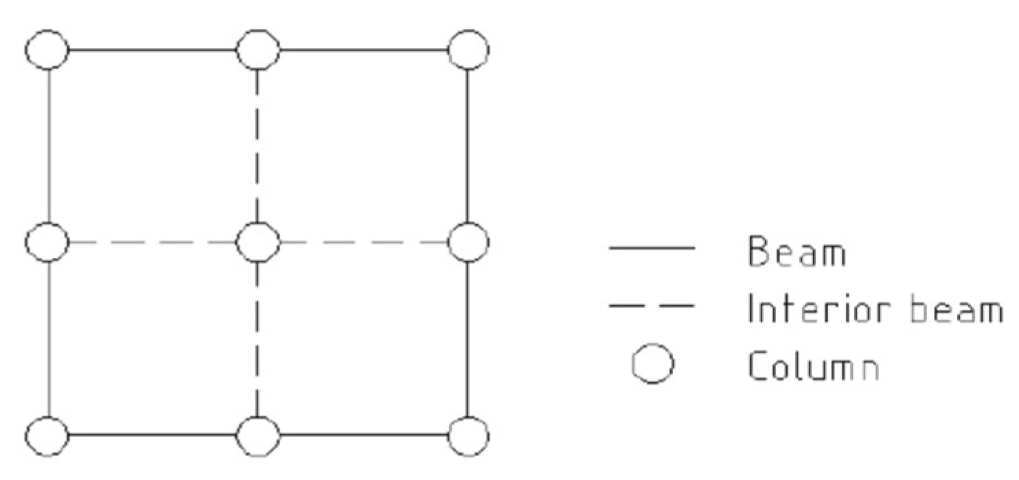
2.2.1. Frame System
One of the most simple and common structural systems is the frame system. It is usually built with frames made of columns and beams. The connections are often rigid, and a flat slab is the most common slab choice. If used, the pinned connection is prepared, and the horizontal loads must be transferred in another way. The most common alternatives here are stabilising trusses or diaphragm action using various sheet materials. Depending on the building size, frames can be used both along the façade and internally [
11,
12]. The frame system can be seen in
Figure 1.
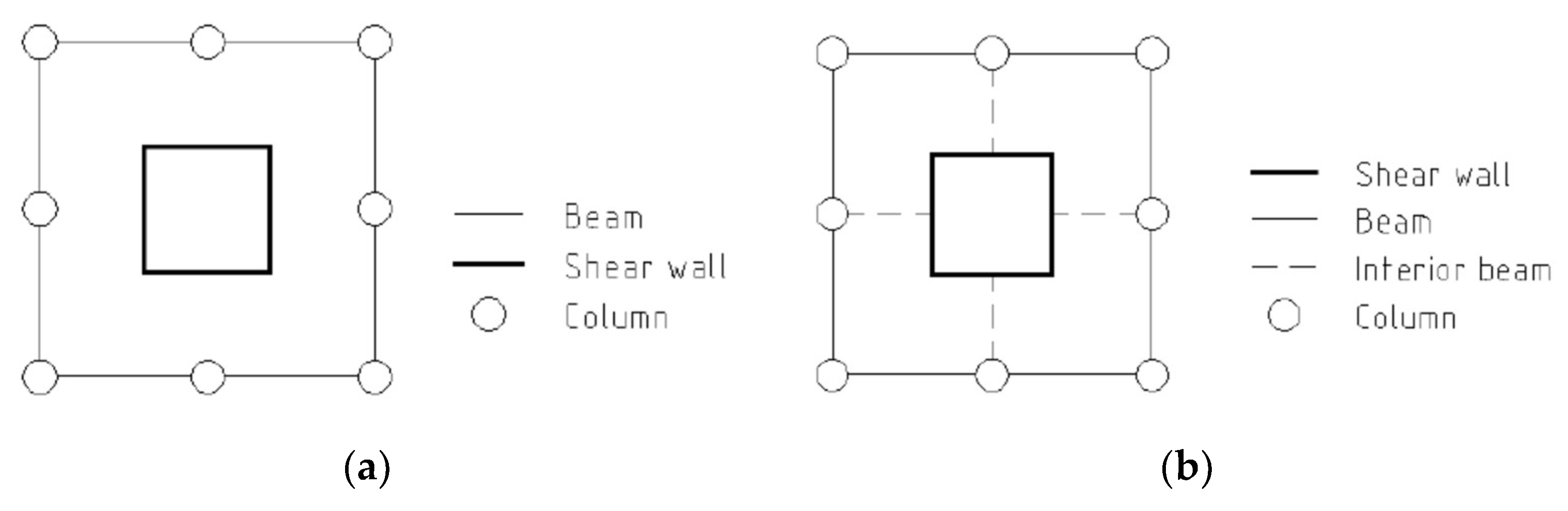
2.2.2. Shear-Wall Systems
A shear-wall system, which is also sometimes referred to as a core system, is one type of system that is built up with shear walls to take care of the lateral loads. The most common way is to have shear walls in two directions, sometimes placed as a core in the middle of the building. The purpose of the shear walls is to work as vertical cantilevers, taking care of all lateral loads and some vertical loads, while letting the other columns in the building take care of only the vertical loads. It is common to have more than one core, for example, with elevators facing each other and then connecting the cores with beams in between [
11,
12]. The shear-wall system is shown in
Figure 2a.
A combination of the frame system and the shear-wall system is also possible. With this combination, it is hard to utilise the frame action due to the typical low heights in rooms. The core and the frames would have different deflections if they were separate, but when they are combined, they are restrained by each other and will create a different, stiffer deflection profile [
11,
12,
17]. The combined system of shear walls and frame can be seen in
Figure 2b.
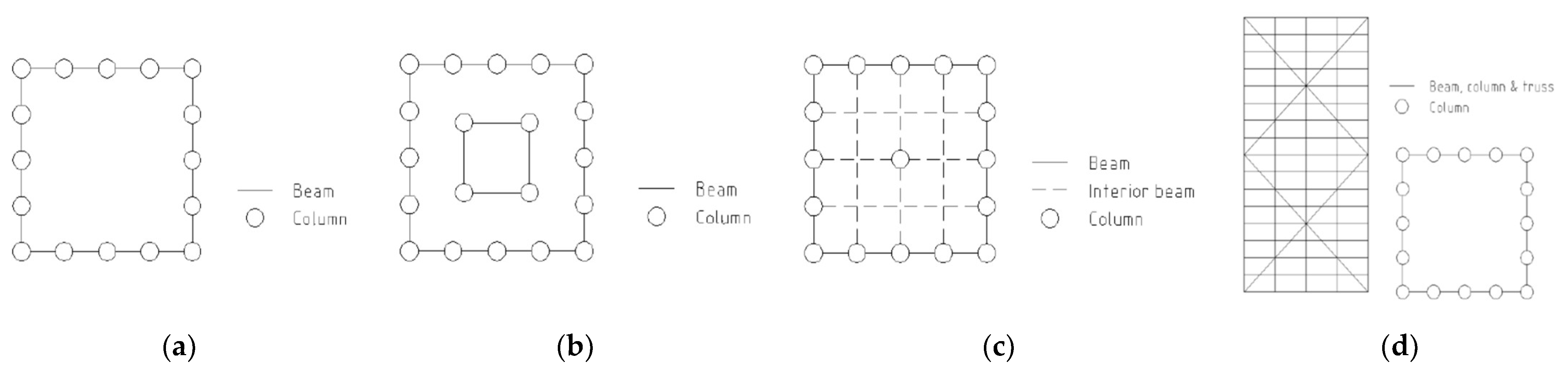
2.2.3. Tube Systems
One system that was introduced by Fazlur R. Khan is the framed-tube system, which has also been a significant factor in developing skyscrapers. There are different kinds of framed-tube systems; they can be hollow, have a tube inside, be bundled, have diagonal bracing at the façade or be outrigger-braced, for example. For the original hollow form, columns are placed close to each other along the façade and connected by beams. The building will act as a stiff cantilever with the possibility to have columns inside to sustain vertical loads [
11,
12,
17]. The framed-tube system is shown in
Figure 3a.
The tube-in-tube system is similar to the system with a shear-wall–frame system, but it has one external and one internal tube. The combination of outer and inner tubes creates a more stable structure for the lateral loads [
11,
12]. The tube-in-tube system can be seen in
Figure 3b.
The bundled-tube or modular-tube system can be seen as a combination of a framed-tube system with internal frames, which creates several sections inside. Small modules in the building will make it more robust at the same time and reduce possible shear lag effects [
11,
12]. The bundled-tube or modular-tube system is shown in
Figure 3c.
There is a braced-tube system that has diagonal bracing frames along the façade to create extra stiffness against lateral loads. These diagonal elements will also help distribute the vertical loads and create a more redundant structure [
11,
12,
17]. The braced-tube system can be seen in
Figure 3d.
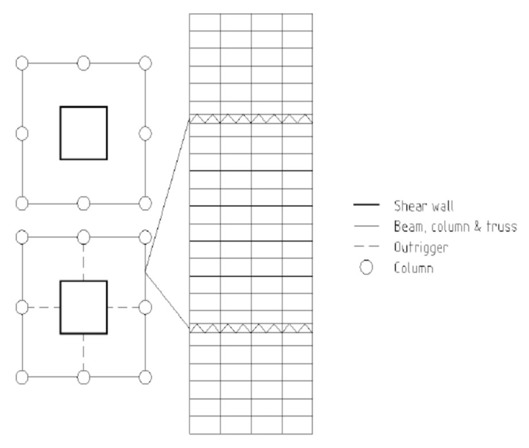
2.2.4. Outrigger Systems
The outrigger-braced system is built up with one extra-large core in the middle and a perimeter tube at the edges. At a certain height of the building, the perimeter columns and the core are connected by outrigger elements, which usually are trusses. These particular levels usually have either trusses or solid walls as facades to redistribute forces from above [
11,
12,
18]. The outrigger-braced system is shown in
Figure 4.
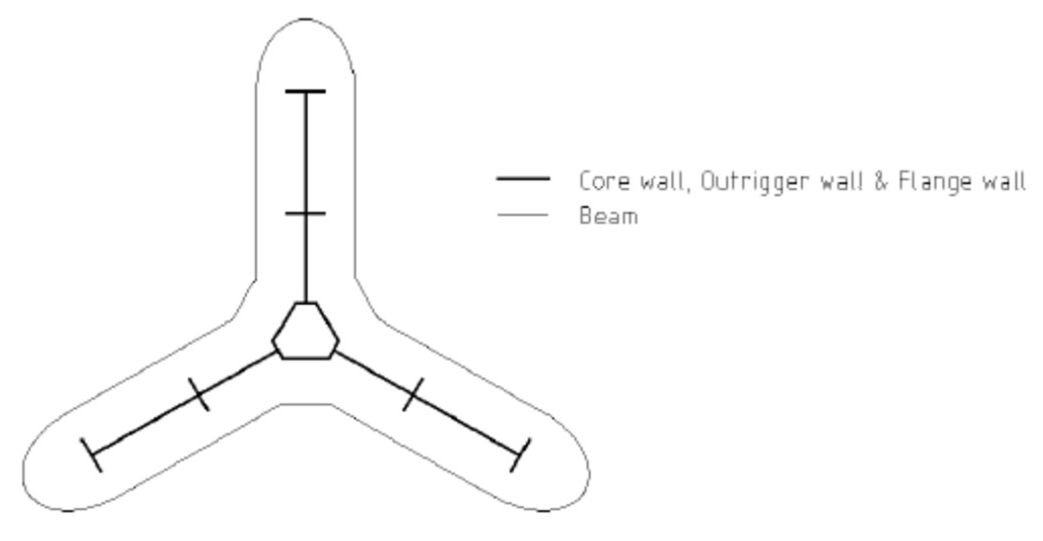
2.2.5. Buttressed Core System
The basic concept of the buttressed core system is its Y-shape acting like a tripod for the structure. Each wing is attached to a hexagonal central core, leading to a highly stable system, where each wing is buttressed by the two other wings. The intention with the structure is that the hexagonal core should give torsional rigidity, whereas the wings give the structure shear resistance and larger inertia for global moment action.
Tower Palace III in Seoul, completed in 2004, was the first building based on this system. It showed high performance both regarding structural behaviour and wind response. Even though this structure was not near the height of modern-day skyscrapers, it showed the great potential of the structural system and building layout [
12,
15].
Spreading the walls within each wing might create higher torsional stability, but it also requires more openings and results in less light in the central parts of each wing. It is therefore advantageous to construct the floor layout in a way that avoids these problems [
12,
15].
Figure 5 shows an example of a simplistic section for a buttressed core system.
The appearance of these structural systems is aesthetically pleasing and seems to be popular in urban high-rise buildings and skyscrapers. They could also be used as a supporting system for kinetic facades, hence reducing the requirement for additional structural elements [
16].
3. Materials and Methods
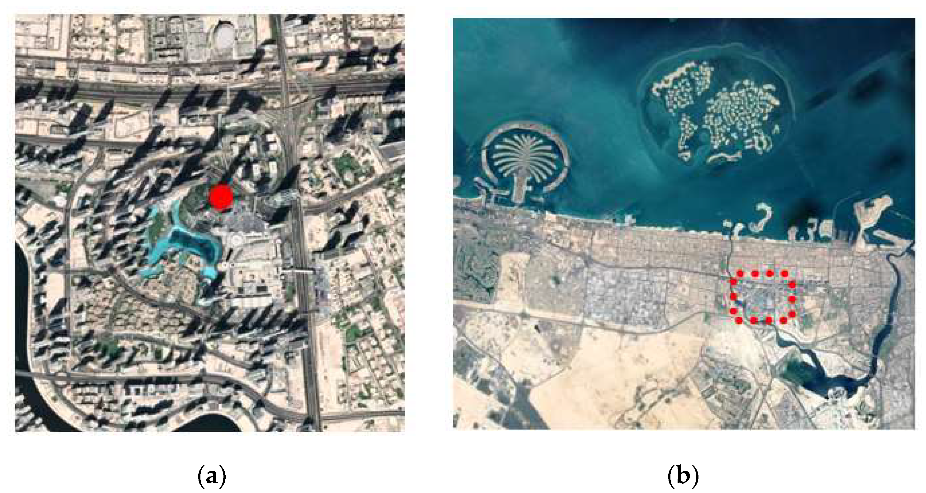
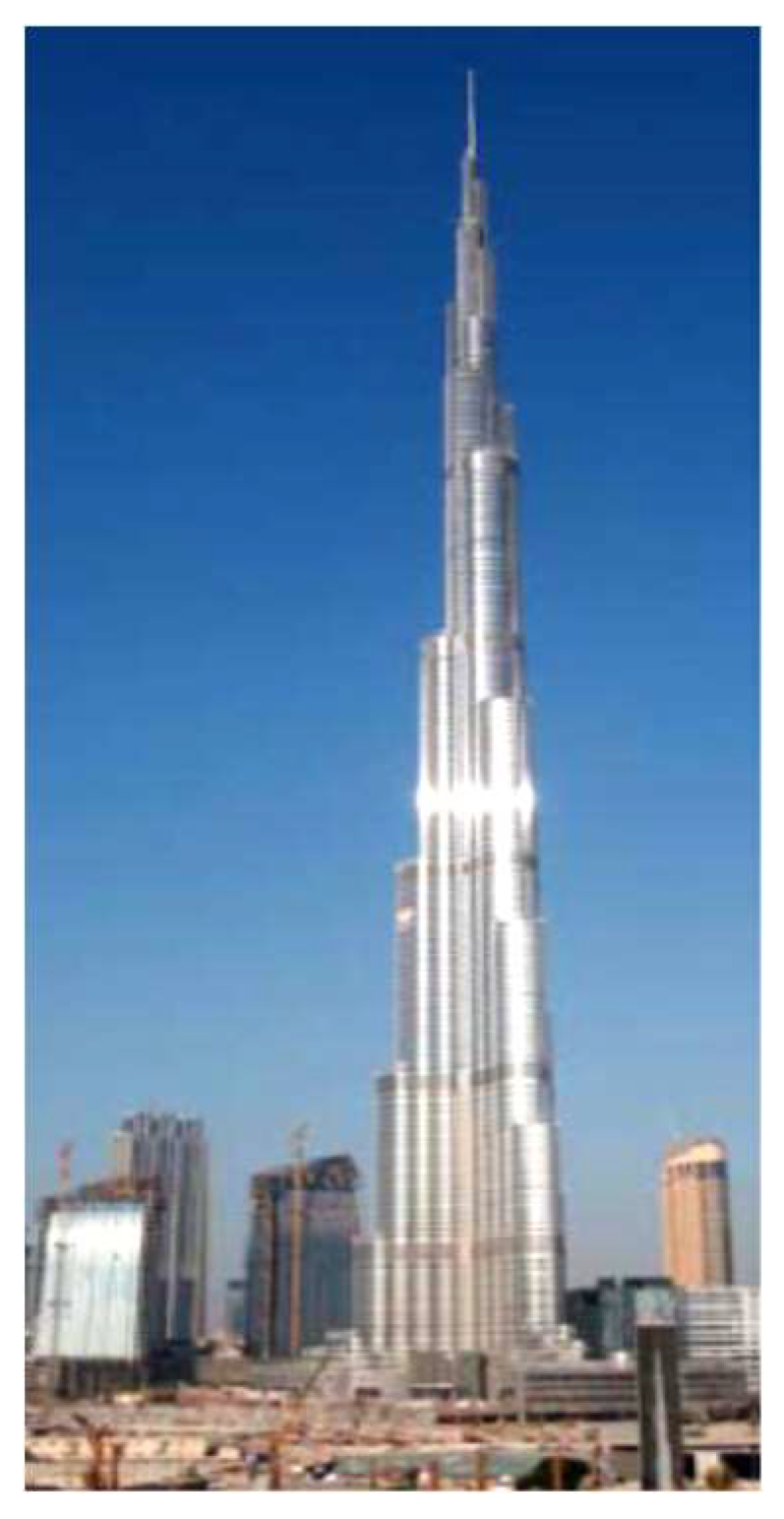
The United Arab Emirates is a country located at the eastern end of the Arabian Peninsula in Western Asia. It borders Oman by the east and Saudi Arabia in the southwest and has maritime borders in the Persian Gulf with Qatar and Iran. Burj Khalifa, formerly known as Burj Dubai, is located at no. 1, Sheikh Mohammed bin Rashid Boulevard, Dubai, United Arab Emirates (see
Figure 6).
4. Case Description
4.1. Burj KhalifaNarrative
Burj Khalifa development is a mix-use complex building with a floor area of about 460,000 square metres that includes parking spaces, offices, apartments, and amenities for shopping, lodging, and recreation. Its design conception is focused on serving as a focal point for a large-scale mega-structure that reaches 828 m. The building has more than 160 floors. The geometrical features of the local arid flower make it a suitable inspiration pattern embodied in the minaret as a crucial component of Islamic architecture. Each of the tower’s three wings has four bays arranged around a central core [
6,
8,
20].
The six-year construction of Burj Khalifa, the world’s tallest structure, began in January 2010. This 828 metre-tall reinforced concrete tower has broken many records. Since this is the first effort, a building of this height was achieved by combining cutting-edge structural design techniques with numerous significant technological concepts utilised to attain the new height [
8,
9].
The tower has 900 private apartments, restaurants, corporate offices, suites, sky lobbies, swimming pools, and surveillance decks. It can house about 35,000 people. In addition to 2909 stairways that run the length and breadth of the building, there are eight escalators and 57 high speed elevators for moving people and goods vertically and horizontally. At lower levels, adequate setbacks ensure that the structure will continue to be connected to its surrounding as more super tall buildings are constructed in the future [
8,
10,
21].
4.2. Structural System Selection Strategies
Approaches for the selection of structural systems vary. Common among them include the consideration of the objectives for incorporating architectural and structural design concepts [
1,
6,
22]. To this end, the following structural strategies are relevant: (i) choose and optimise the appropriate tower structural system for redundancy, added strength, and stiffness, as well as reduction in the construction period and cost; (ii) involves the utilisation of recent technological advances alongside the local skilled labour and method of construction prevalent in the local market; (iii) control and establish the gravity force resisting method to increase its use in defying the lateral loads aiming at balancing comfort and conducive living inherent in luxurious residential and hotels; (iv)involve the recent technological advancement in the areas of analysis, design, construction, and materials elements; (v) control the building acceleration and velocity, drift, and torsional movements within an acceptable design standard; (vi) manage the virtual displacement within the vertical members; and (vii) limit the dynamic reaction during wind loading through regulating the structural behaviour of the tower, enhancing its dynamic characteristics as well as forestalling impound vibration as a result of the vortex shedding [
6].
It is also noted that the favourable dynamic behaviour of the structure was attained through the following:
To diminish the dynamic wind excitations, the building form creates a spoiler-type of effect along the height of the tower.
Altering the building shape as the height increases ensures that continuous gravity and a lateral-load-resisting system continue without interruption.
Scaling of the floor plans along the height efficiently tapers the building silhouette.
Whereas numerous structural alternatives were considered, high-performance concrete was chosen as the main material for the tower construction. This is also cognizant of its stiffness, continuity, high strength, mass, moldability, speed of construction, and pumping aptitude, as well as the building’s intended use as residential quarters [
6,
23].
4.3. Survey Monitoring Programs
The tower was built using a variety of in-depth survey programs and the most recent geodetic electro-optical total station technology. These tools offer significant precision throughout the whole surveying process because they offer a fixed reference point for the total stations with known coordinates.
The use of fixed points, however, with the persistently escalating altitude made it challenging to exploit the ground-level fixed points because the distance between them and the total station at the highest construction level became too much for precise referencing and the virtual space between the fixed points became too small [
6,
17]. The survey programme also unveils that the tower’s growing height, slenderness, and movement at some construction stages complicate the accuracy even more. The cause of the movement during the construction phase is as follows:
Basement/foundation settlement;
Construction progression;
Dynamic-wind stimulations;
Concentrated and outsized crane loads at the highest constructed level;
Column curbing was due to shrinkage effects, creep, and elasticity;
Irregular solar effects that might result in building tilt;
Steel structure and concrete mixture (from the base to level 156 and to the peak of the pinnacle);
The structure’s lateral drift under gravitational loads is a result of uneven load distribution relative to the tower’s centre of rigidity;
Due to daily temperature variation, the temperature at the apex and the lower altitude can differ by 150 mm in six hours.
Rationalising these actions generated an amount of intricacy that needed to be taken into consideration when setting the structure at the proper theoretical design spot. As a result, this necessitated an in-depth survey monitoring programme to give the precise structural location at some particular moment [
1,
6].
Previous studies highlighted useful strategies to overcome the challenges explained above, which are mainly associated with absolute control. Those studies also highlighted the importance of positioning the building in an appropriate location relative to the vertical axis requirement. First is the survey team’s perception of the structural movements and behaviour during the construction phase; second, the creation of a comprehensive monitoring programme for all structural elements that have an impact on the tower movement; and finally, the installation of contemporary “measurement system” that draws on the recent advances in GPS technology. Of note, the Leica Geosystem and clinometers, as well as the precision inclination sensors, collectively produce instantaneous, reliable tower positioning at the highest construction level, even while it is in motion.
4.4. Foundation System
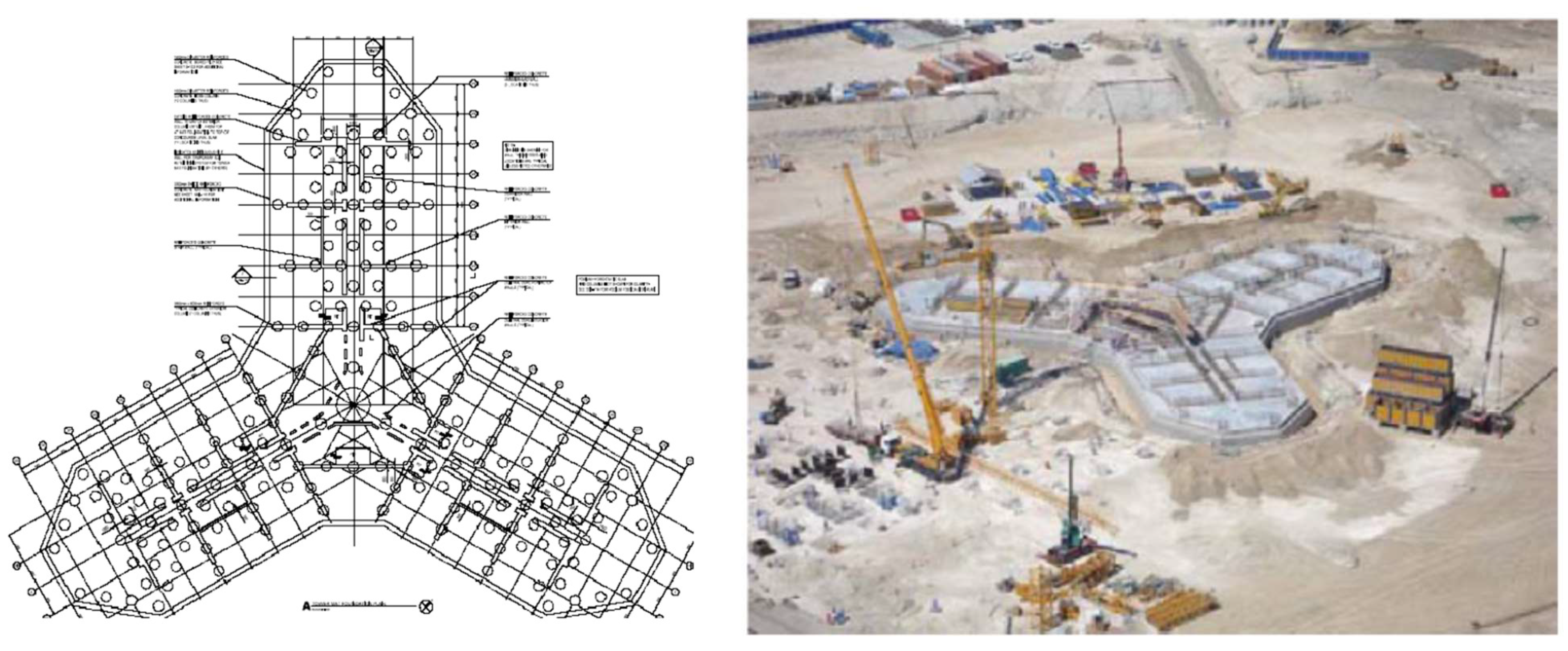
As shown in
Figure 7, the raft foundation was established on a 3.7 metre-deep high-performance reinforced concrete pile. It draws on a high-performance self-compacting concrete (SCC), which is placed over a blinding slab of no less than 0.1 metres in thickness over a waterproofing membrane, over an at least 0.5 metre blinding slab [
6,
21].
The tower was erected about 45 m beneath the surface of the raft on 192–150 mm diameter high-performance reinforced concrete bored piles. Self-compacting concrete (SCC) with a water–cement ratio of at least 0.30 is used in one continuous concrete using the tremie method [
6,
21]. Additionally, the corrosive soil condition at the site utilises full cathodic shield systems and waterproofing membranes to maintain alignment.
4.5. Floor Framing System
The interior core wall and exterior columns are connected by a 200 mm to 300 mm two-way reinforced concrete flat plate slab, which spans nearly nine (9) metres. The slab was later changed to a flat plate construction within the accommodation (hotel and residential) floor-framing system of the building, with a 50 mm supplement tapering the prop position.
A 225 mm to 250 mm two-way reinforced concrete slab system with 150 mm drop panels makes up the floor-framing system at the tower tip [
6] to balance the stress distribution at all vertical components.
Figure 8 depicts the typical floor-framing plan at both mechanical and residential levels.
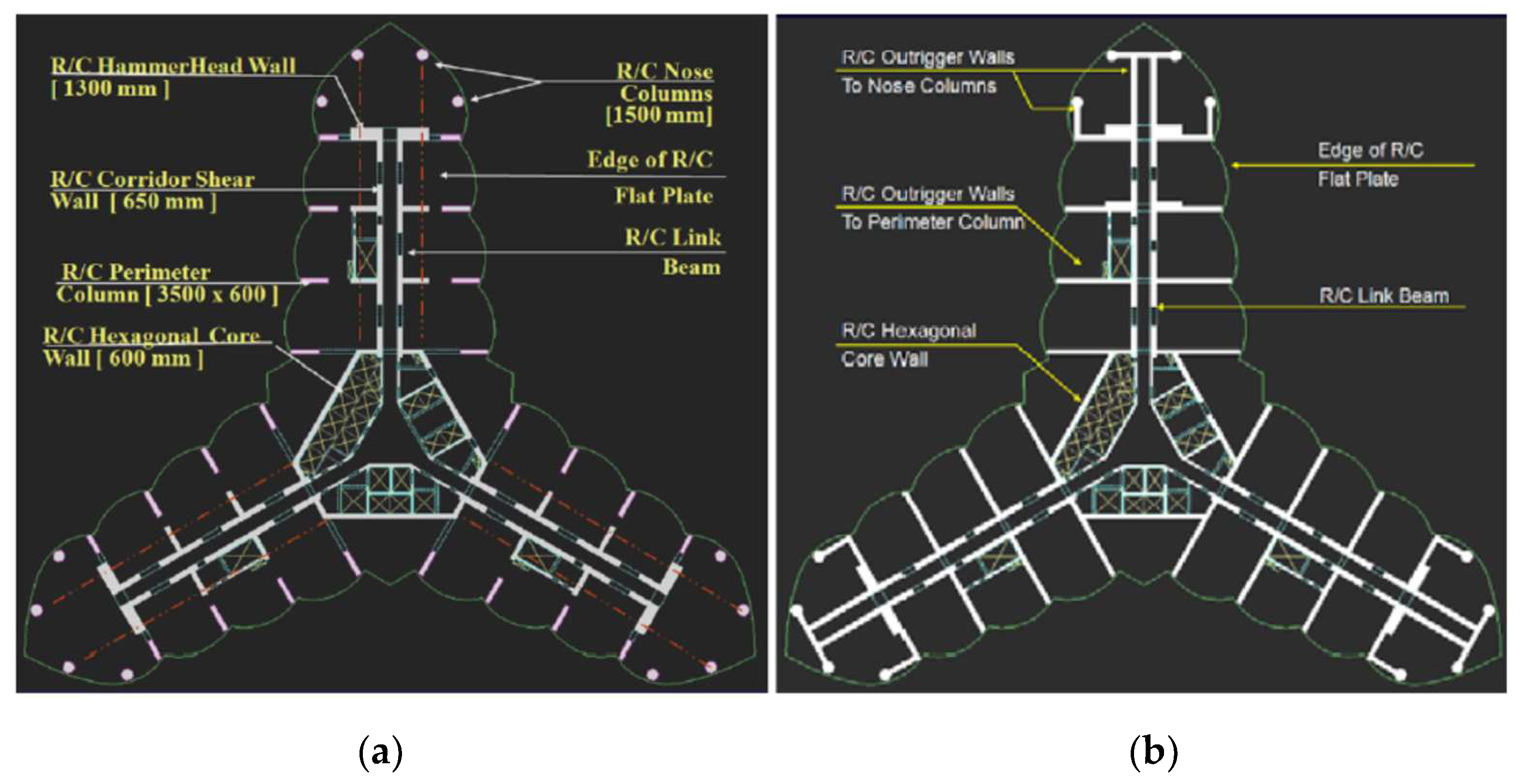
4.6. Lateral Load Resisting System
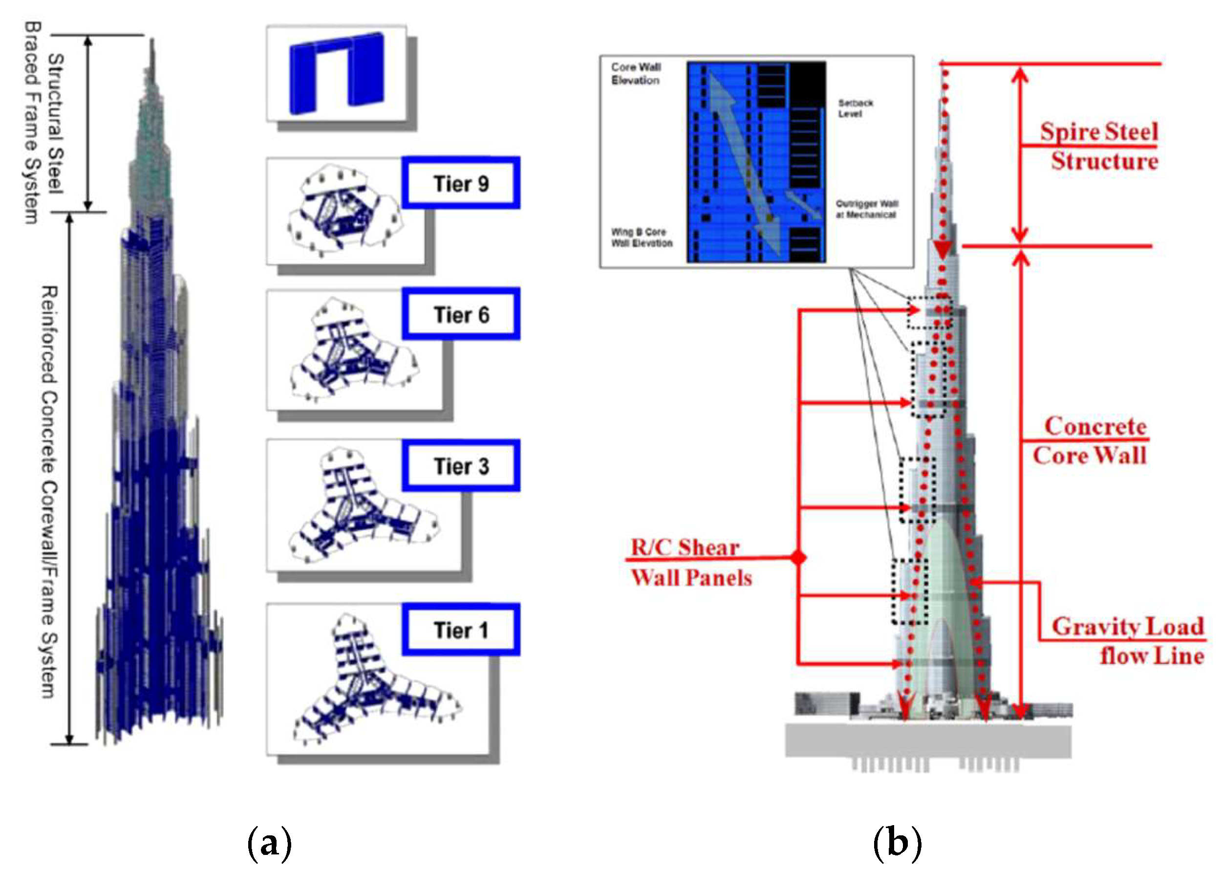
As reported in [
6], the towers’ lateral load resisting system consists of high-performance, exterior reinforced concrete columns connected to the reinforced concrete ductile core walls via a sequence of shear wall panels at the mechanical levels as shown in
Figure 9a.
The thickness of the core walls varies between 500 mm and 1300 mm. At every level, they are typically connected by composite tie beams in the thickness range of 500 mm and 1300 mm. or a succession of 800 mm to 1100 mm deep reinforced concrete. Ductile composite tied beams are present in some specific areas of the core wall system as a consequence of the restriction on the connection beam depths. These ductile composite connection beams usually entail structural steel built-up I-shaped beams, or steel shear plates, with shear studs fixed in the concrete section. Typically, the beam width and the adjacent core wall thickness correspond [
6,
8,
24].
The tower’s soaring spire sits atop the world’s tallest building, which is a central reinforced concrete core wall. From level 156 to the peak of the spire at about 750 metres above sea level is a lateral load resisting diagonal steel bracing. The tip is made up of a structural steel pipe section that ranges in diameter from 2100 mm at the base to 1200 mm at the 828 metre summit [
6,
23].
4.7. Structural System Optimisation and Gravity Load Management
Whereas gravitational load is important as a design criterion to be considered in tall buildings, it has an instant effect on the general performance and efficiency of the tower. Thus, it should be addressed during the architectural conceptualisation and structural design conception formation stages. While the wind behaviour of super-tall buildings continues to be the key design criteria to take into account, the process of redistributing and mobilising gravity load is the biggest threat to the efficiency demand [
6,
10].
Figure 9b provides the gravity load assessment carried out by engineers, while Skidmore Owings & Merrill LLP (SOM) evaluates the concrete area required to sustain the tower gravity loads [
6] without having to reduce the member sizes. The complete amount of materials required to withstand the gravitational load and that needed to resist the combined effect of gravity and lateral loads are identical. This validates the efficacy of the structural system. The nose columns and the hammer walls positioned at the apex of the tower, play a significant role in the building moment and its ability to resist the overturning moment.
Also notable is the gravity load flow management alongside the height of the tower as illustrated in
Figure 9b [
6]. The restrictions on the wall thicknesses (500–600 mm) of the centre core and the wing walls thickness (600 mm) permit the gravity load to easily flow into the centre and demonstrate the art of working with concrete. For maximum horizontal load resistance, the spine web walls (650 mm), the nose columns and the hammer headwalls maintain the utmost resistance to lateral loads. The strain gauges are also set up to monitor the gravity load flow. Thus, the reinforced concrete central core wall at level 156 offers a stand support for the spire and pinnacle structure.
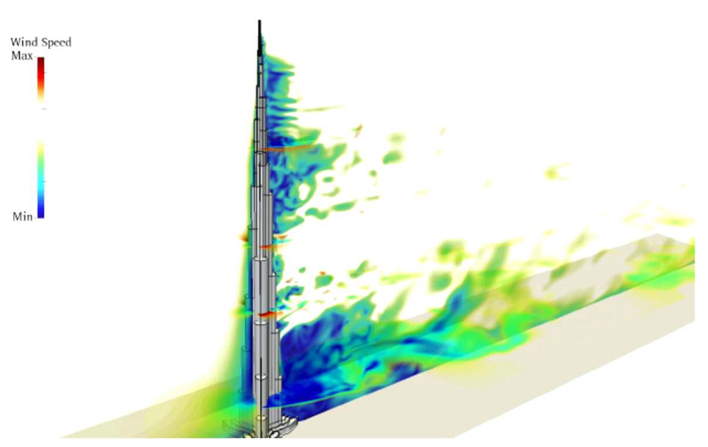
4.8. Wind Engineering Control
While the wind effect is an important consideration when designing, planning, and constructing high-rise buildings, Burj Khalifa is not an exemption, as it reaches its full height owing to its adherence to the Y-shaped plan concept. In a study performed on Sim-Scale (CFD simulation platform), as shown in
Figure 10, the tower design with different model configurations illustrates an effective performance in the mitigation of wind effects [
25].
Numerous wind engineering techniques help in the dynamic response of the building under wind loading by altering the vortex shedding pattern (direction and frequency) and the dynamic behaviours of the building to enhance its dynamic performance and also to avoid lock-in vibration [
6,
24].
A 3D finite component analysis model for Burj Khalifa was created to consider the authentic material properties and evaluate the real measured building displacements (x, y, z) for the predicted movements. This assessment model aims to estimate the cross displacement among other factors due to any seismic or wind events during construction and after the completion of the structure [
8,
17,
25].
One of the most thorough surveys is the creation of the review and structural health monitoring (SHM) scheme for wind/seismic-related features. This involves, among other things, the following:
Installation of provisional real-time monitoring design to check the building dynamic and displacement response under seismic and wind loads throughout the construction.
Setting up a permanent real-time monitoring system to investigate the building dynamic and displacement response under seismic and wind loads.
Providing adequate data to forecast the low energy behaviour of the pinnacle under low/fair/rigorous seismic and wind excitations.
Surveys and health monitoring research inception have generated a lot of interest and insight into the actual insitu material properties, the building’s structural performance and feedback under wind and seismic excitations, as well as constant change in the tower’s distinctiveness during and after construction.
Wind engineering management of the building resulted from modifying the tower shape alongside the height, while progressing, without disruption, the lateral load resisting system and building gravity [
6]. These were mostly achieved through the following:
Reducing the floor plan area alongside the height, consequently narrowing the structure profile;
Using the building form to set up a spoiler kind of outcome along the entire height of the building, including the pinnacle, to lessen the dynamic wind excitations;
Transforming the orientation of the structure in response to wind bearing, hence strengthening the building’s normal to the worst wind direction.
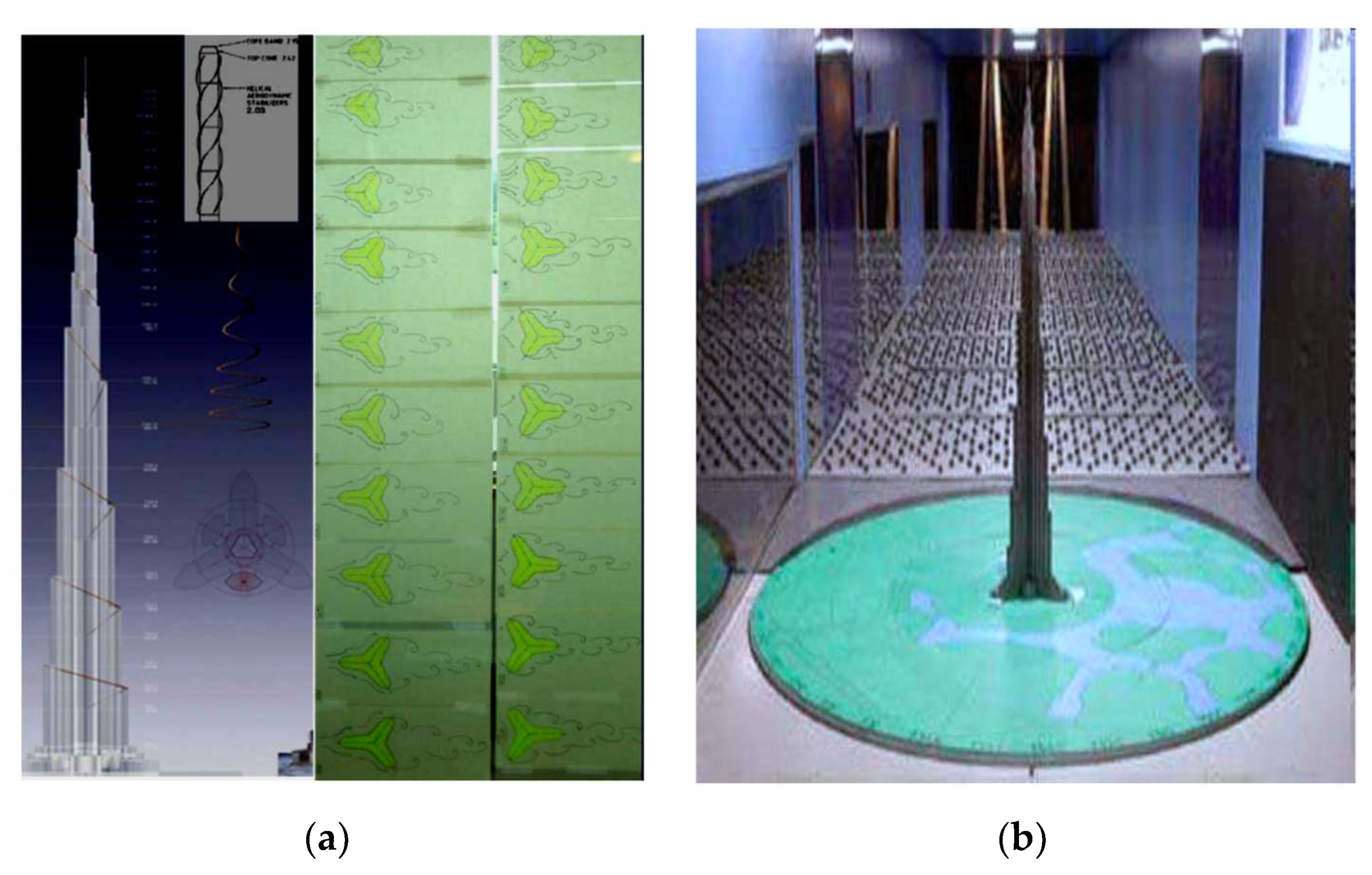
As the project commenced, rigorous wind tunnel monitoring and evaluation regimes exposed a thorough understanding of the structure of wind behaviour and reaction to verify the wind engineering control strategies. This contains regulating the building mode shape with innate frequencies to improve the structural dynamic response against wind excitations [
8].
Figure 11 unveils the early conceptual sketches prepared to express the effect of altering the form of the tower along its height from the beginning of the design schematic stage to minimise the wind forces on the building. The disparity of the building form, and width, brought wind vortices around the boundary of the tower that behaved in various ways for different shapes at different frequencies, consequently disorganising the relations between the building shape and the wind [
6,
25].
4.9. Engineering and Architectural Design Concepts
The design concepts of Burj Khalifa are organic, naturalism, and bio-mimetic. As illustrated in
Figure 12, the structure was based on a geometric scheme, the design adopted the concept of form and that of the plan; the concept of form was inspired by spiral minarets that can be traced back to Islamic architecture and integrated historical and cultural elements of the Middle East, while the plan concept was originated from the
Hymenocallis flower (inspired by the triple-lobed footprint). The Y-shaped floor plan shape induces an onion dome shape, which serves as buttress to the hexagonal core while keeping the tower firm. The shape also presents amazing scenery, enhancing the environment, as well as the Persian Gulf.
As the building spirals to its apex, one outer bay peels out at each seventh floor. Unlike various super-tall structures, it admits into the interior an ample and adequate natural lighting condition, which is one of the criteria that helped Skidmore Owings and Merrill to secure the project [
23].
4.10. Component and Material Elements
With the exception of the spire of the tower, this is composed of structural steel, concrete serves as the building’s primary structural material throughout. The external cladding system, which resists intense heat, consists of vertical fins of aluminium and textured stainless steel spandrel panels as well as reflective glazing [
10]. As a result, the bigger openings were fully covered with translucent glasses, and the steel structure was supplemented with hard materials, such as brick or terra cotta. Unlike the typical load-bearing masonry or brick wall partitions, these claddings only support their weight and the lateral wind force. With the creation of the new structural system, curtain walls and new cladding ideas were adopted [
6]. Furthermore, Ref. [
7] claims that the essential components of the vertical and horizontal structural system are the columns, beams, outriggers shear walls, and shear trusses. These elements are generally prominent in most reinforced concrete and steel buildings.
As regards concrete, the building used self-consolidating concrete (C60 and C50) for piles and rafted foundation, 80-MPa concrete for columns and core walls up to around 440 metres, and 60-MPa for the remaining height of about 586 metres. The largest aggregate size in the 80-MPa mixture is 20 mm, and it contains 10% silica fume, 13% fly, and an average slump flow of about 600 mm. The structural necessity reduces to 60MPa with a mix containing a10 mm maximum gauge aggregate when the pumping pressure is at or above 200 bars near floor 127 [
21,
24].
Prior to the construction of the Burj Khalifa, concrete was pumped to higher elevations using concrete that was of a lesser grade to maintain its workability. The Burj Khalifa used single-stage pumping technology, pumping high-strength concrete to 586 metres above the ground, breaking, or rather surpassing, the previous records set in 1994 by pumping 25 MPa concrete to 532 metres in the Riva del Garda hydroelectric power plant [
24,
26].
5. Summary and Conclusions
The key structural element for this mega tall tower is termed a “buttressed core structural system” that offers a remarkable progression in height. It entails a three-winged structure attached to a central hexagonal resilient tube, where each wing is braced to the other to offer a decisive and stable structure. The wings provide an increased moment of inertia and shear resistance, while the central core offers the torsional resistance for the entire structure.
Additionally, regulating the building plan outcome and the variation in plan shape or dimensions throughout the height of the building can be attained by reducing and changing the plan shape. Meanwhile tapering and setback forms were adopted to minimise the wind intensity; thus, the excess pressure is evident.
It is noted that ever since the structural health monitoring (SHM) programme was installed at the Burj Khalifa, a good amount of the structural system behaviour has been recognised and incorporated, measuring the (i) structural acceleration at every level; (ii) structural displacements at level 160M3; (iii) wind speed and direction alongside the tower height at most balcony zones, which still require calibration to share the fundamental wind profile; (iv) tower dynamic frequencies, with higher modes; (v) anticipated tower damping at low amplitude as a result of both seismic and wind events; and (iv) the records at the bottom of the tower.
Differentiating between the expected insitu measured response and the structural behaviour is outstanding, although some results cannot be unveiled here because of confidentiality.
A previous study in the context of comprehensive SHM programs at the Burj Khalifa shows that the advancement is as given below:
- (a)
Examining all concrete grades to verify their properties: the heat of hydration, split cylinder, modulus of elasticity, strength, durability, creep, shrinkage characteristics, etc.
- (b)
To evaluate the foundation settlement, column shortening, and building a lateral movement from the commencement phase of construction till the end for survey monitoring programmes.
- (c)
For an efficient tension monitoring programme, the initial pull in the walls, columns, and near the outrigger levels was calculated to verify the load transfer to the outer mega columns.
- (d)
To monitor the tilt of the structure in real time and examine lower-grade concrete using GPS technology to validate the load transferred to the outer mega columns and to measure the structure tilt in realtime, as well as the use of GPS technology in the inspection process for an efficient survey program.
This study reviewed the design and structural health monitoring programme of the tallest building as well different construction practices in a mega-tall building in recent times. While the remarkable landscape and its structural systems presented in this research are certainly an astounding accomplishment, developing technologies and designs extendsfurther beyond sustainable vertical built environments.
The study concludes that torsion stiffness as well as wind load mitigation in mega-tall buildings are influenced by initial phase design decisions, particularly those that concern the model and plan arrangements. By integrating devices such as wind tunnel investigation, wind analysis studies, and (CFD) simulation into the design process, as illustrated in
Figure 10, multidisciplinary aerodynamic plan assessments can be made. Collaboration is essential in decision making at the initial design phase, as it broadens the perception and enhances the design approach and patterns.
Based on the foregoing, the study hereby revalidates the following:
Planning and construction of the Burj Khalifa’s structural and foundation systems.
Planning and development of the building components, and method of the tower.
Achievement of “Full-Scale Monitoring Program” under the wind in the structure.
The real performance of the tower by verifying the design hypothesis, concrete material behaviours, and systematic modelling presumptions and methods, which led to the advancement of the in-depth structuralhealth and survey monitoring programme to facilitate instant response to the real structural performance of the building from the commencement of construction and all through its lifespan.
6. Future Study/Program
Two key reservations affected the outcome of this research, the design model and the aerodynamic engineering management. Reviewing prior literature indicates that there are more opportunities for research regarding the health monitoring programme of tall buildings. Hence, more research in the field of wind engineering can contribute to considerate aerodynamic buildings, and advance architectural design. Further knowledge in this field is required.
Author Contributions
Conceptualisation, D.A.Y. and A.A.; methodology, D.A.Y. and A.A.; validation, D.A.Y., A.S., A.S.N. and A.A.Y.; formal analysis, D.A.Y., A.A.Y. and A.A.; investigation, A.S., A.S.H. and A.Y.; resources, A.A. and A.M.U.; data curation, D.A.Y. and A.M.U.; writing—original draft preparation, D.A.Y. and A.A.; writing—review and editing, D.A.Y., A.T.Z. and A.A.; supervision A.A.Y. and A.A.; project administration, A.S.H. and D.A.Y.; funding acquisition, A.A.Y., A.S.N., A.M.U., A.S., A.Y., A.S.H., A.T.Z. and A.A. All authors have read and agreed to the published version of the manuscript.
Funding
This research received no external funding.
Data Availability Statement
This study remains review article that assesses and examines established data; as such no supplementary/new data were created.
Acknowledgments
The authors gratefully appreciate the support from the council on tall building, and urban habitat Korea through IJHRB for granting permission to access/re-use supplementary data that inform of imagery figures aligned with the SHM Program. We also thank the Chalmers open digital repository (ODR) and Horizon Research Publishing (HRPUB) for their open access services. All supplementary data and imagery sources are appropriately cited.
Conflicts of Interest
The authors declare no conflict of interest.
References
- Ali, M.M.; Moon, K.S. Structural developments in tall buildings: Current trends and future prospects. Archit. Sci. Rev. 2007, 50, 205–223. [Google Scholar] [CrossRef]
- SS-ISO 10137:2008; Bases for Design of Structures—Serviceability of Buildings and Walkways against Vibration (ISO 10137:2007, IDT). SIS: Stockholm, Sweden, 2008.
- Djoki, V. Morphology and Typology as a Unique Discourse of Research. SAJ Serb. Archit. J. 2009, 1, 107–130. [Google Scholar]
- Stanley, B.W.; Stark, B.L.; Johnston, K.L.; Smith, M.E. Urban Open Spaces in Historical Perspective: A Transdisciplinary Typology and Analysis. Urban Geogr. 2012, 33, 1089–1117. [Google Scholar] [CrossRef]
- Zhang, Y.; Wei, T. Typology of religious spaces in the urban historical area of Lhasa, Tibet. Front. Archit. Res. 2017, 2, 384–400. [Google Scholar] [CrossRef]
- Abdelrazaq, A. Validating the structural behavior and response of Burj Khalifa: Synopsis of the full scale structural health monitoring programs. Int. J. High-Rise Build. 2012, 1, 37–51. [Google Scholar]
- Gunel, M.H.; Ilgin, H. Tall buillddings: Structural Systems and Aerodynamic Form; Routledge: London, UK, 2014. [Google Scholar]
- Smith, A. Burj Dubai: Designing the world’s tallest. In Tall and Green: Typology for Sustainable Urban Future, Proceedings of the 8th CTBUH World Congress, Dubai, United Arab Emirates, 3–5 March 2008; Wood, A., Ed.; Council on Tall Buildings and Urban Habitat (CTBUH): Chicago, IL, USA, 2008; pp. 36–42. [Google Scholar]
- Subramanian, N. Burj Khalifa World’s Tallest Structure. New Build. Mater. Constr. World 2010, 7, 198–210. [Google Scholar]
- Ali, M.M.; Al-Kodmany, K. Tall buildings and urban habitat of the 21st century: A global perspective. Buildings 2012, 2, 384–423. [Google Scholar] [CrossRef]
- Truby, A.; Banks, C.; Burridge, J.; Cammelli, S.; Chiorino, M.; Ha, T.; Jaeger, J.-M.; Keleris, G.; Marsh, S.; Romo, J.; et al. Tall buildings. In Reinforced Concrete Design; Subject: Engineers & Technology; CRC Press: Boca Raton, FL, USA, 2014. [Google Scholar] [CrossRef]
- Gyllensten, S.; Modig, A. The 200 m Timber Tower—A Study on the Possibilities of Constructing a 200 Meter Tall Timber Building; Chalmers University of Technology Gothenburg: Göteborg, Sweden, 2020. [Google Scholar]
- Girard, L.F. Toward a Smart Sustainable Development of Port Cities/Areas: The Role of the “Historic Urban Landscape” Approach. Sustainability 2013, 5, 4329–4348. [Google Scholar] [CrossRef]
- Yusuf, D.A.; Zhu, J.; Nashe, S.A.; Usman, A.M.; Sagir, A.; Yukubu, A.; Hamma, A.S.; Alfa, N.S.; Ahmed, A. A Typology for Urban Landscape Progression: Toward a Sustainable Planning Mechanism in Kano Metropolis, Nigeria. Urban Sci. 2023, 7, 36. [Google Scholar] [CrossRef]
- Baker, W.F.; Pawlikowski, J.J. Higher and higher: The Evolution of the Buttressed Core. Civ. Eng. Mag. Arch. 2012, 82, 58–65. [Google Scholar] [CrossRef]
- Shete, D.P. Use of Dampers in Vertical cities: Effective Method to Control Seismic Vibrations. Int. J. Eng. Res. 2018, 7, 80–82. [Google Scholar] [CrossRef]
- Moon, K. Structural Systems for Tallest Buildings and Their Applications. In Proceedings of the 7th International Conference on Modern Research in Civil Engineering, Architectural & Urban Development, Munich, Germany, 19–21 October 2018. [Google Scholar]
- Sevalia, J.; Desai, A.; Vasanwal, S. Effect of Geometric Plan Configuration of Tall Building on Wind Force Coefficient Using CFD. Int. J. Adv. Eng. Res. Stud. 2012, 1, 127–130. [Google Scholar]
- Maxar, T. High-Resolution Google Earth Imagery. 2023. Available online: https://www.google.com (accessed on 2 April 2023).
- Jin, X.; Zhang, G.; Zuo, J.; Lindsay, S. Sustainable High-rise Design Trends—Dubai’s Strategy. Civ. Eng. Archit. 2013, 1, 33–41. [Google Scholar] [CrossRef]
- Aldred, J. Burj Khalifa—A new high for highperformance concrete Proceedings of the Institution of Civil Engineers. In ICE Civil Engineering; Thomas Telford Ltd.: London, UK, 2010; Volume 163, pp. 66–73. [Google Scholar]
- Ho, G.W.-M. (Ed.) Arup’s Tall Buildings in Asia: Stories behind the Storeys; Routledge: London, UK; New York, NY, USA, 2018. [Google Scholar]
- Abdelrazaq, A. Design and construction planning of the Burj Khalifa, Dubai, UAE. In ASCE Structures Congress; ASCE: Orlando, FL, USA, 2010. [Google Scholar]
- Nehdi, M.L. Only tall things cast shadows: Opportunities, challenges and research needs of self-consolidating concrete in super-tall buildings. Constr. Build. Mater. 2013, 48, 80–90. [Google Scholar] [CrossRef]
- Al-Najjar, S.F.; Al-Azhari, W.W. Review of Aerodynamic Design Configurations for Wind Mitigation in High-Rise Buildings: Two Cases from Amman. Civ. Eng. Archit. 2021, 9, 708–720. [Google Scholar] [CrossRef]
- Aldred, J. Pumping concrete on the Burj Dubai. In Terence C. Holland Symposium on Advances in Concrete Technology, Proceedings of the 9th CANMET/ACI International Conference on Fly Ash, Silica Fume, Slag and Natural Pozzolans in Concrete, Warsaw, Poland, 20–25 May 2007; American Concrete Institute: Farmington Hills, MI, USA, 2007. [Google Scholar]
| Disclaimer/Publisher’s Note: The statements, opinions and data contained in all publications are solely those of the individual author(s) and contributor(s) and not of MDPI and/or the editor(s). MDPI and/or the editor(s) disclaim responsibility for any injury to people or property resulting from any ideas, methods, instructions or products referred to in the content. |
© 2023 by the authors. Licensee MDPI, Basel, Switzerland. This article is an open access article distributed under the terms and conditions of the Creative Commons Attribution (CC BY) license (https://creativecommons.org/licenses/by/4.0/).


 ,
, 


