Article

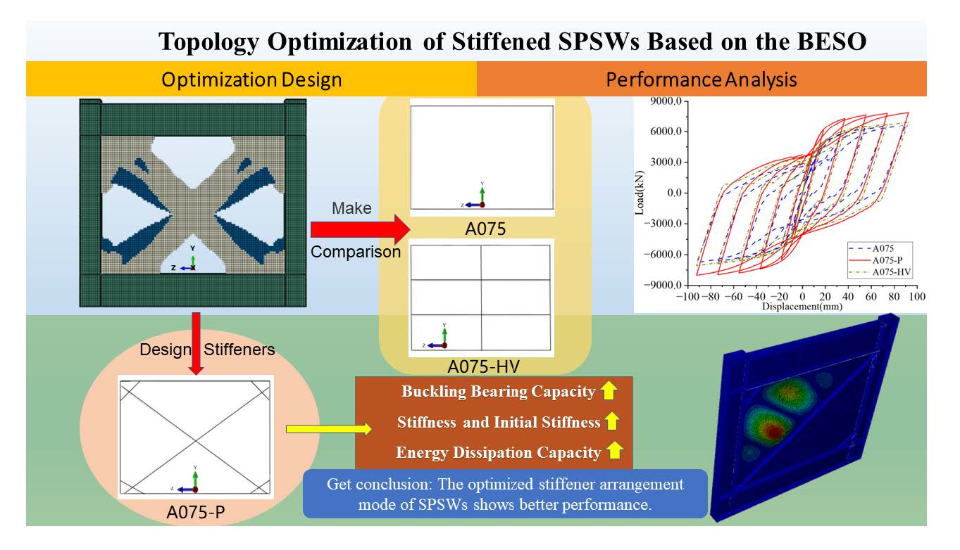
Topology Optimization of Stiffened Steel Plate Shear Wall Based on the Bidirectional Progressive Structural Optimization Method

School of Civil and Transportation Engineering, Guangdong University of Technology, Guangzhou 510006, China
*
Author to whom correspondence should be addressed.
Buildings 2023, 13(3), 831; https://doi.org/10.3390/buildings13030831
Submission received: 4 February 2023 / Revised: 12 March 2023 / Accepted: 17 March 2023 / Published: 22 March 2023
(This article belongs to the Section Building Structures)

Abstract

:
Many studies on structural topology optimization of steel plate shear walls have been conducted. However, research on topology optimization using the bidirectional evolutionary structural optimization method is limited. Accordingly, this study optimized the topology of the stiffening effect of steel plate shear walls (SPSWs) based on this method. A finite element model of the SPSW was established using Abaqus software through the “sandwich” modeling method. An optimization region was expanded into two optimization regions. As the optimization targets, SPSWs with different aspect ratios were selected. Elastoplastic optimization of a single-layer SPSW was performed through the horizontal displacement cyclic loading, and the distribution law of the stiffening effect was obtained. The stiffeners on the SPSW were arranged according to the SPSW-A075 scheme. Monotonic and reciprocating loading simulation tests were performed on the unstiffened SPSW and common transverse and longitudinal stiffeners to analyze their mechanical properties. The results show that the optimized layout of the stiffened SPSW demonstrated better seismic performance and energy dissipation capacity. The buckling bearing capacity increased by 2.17–2.61 times, and the stiffness and initial stiffness improved significantly.

Graphical Abstract

1. Introduction

Structural topology optimization has been extensively studied in structural optimization design. In 1992, Xie and Steven [1] first proposed the evolutionary structural optimization method, which makes the structure “evolve” into an optimal form. The inefficient materials in the structure are gradually removed during optimization. The algorithm is simple and easy to connect with the finite element analysis program. Moreover, it is increasingly being used in structural topology optimization. After a breakthrough, Xie and Huang [2,3] proposed bidirectional evolutionary structural optimization, which can delete and recover deleted units according to sensitivity. In 2007, Xie and Huang [4] further improved the stiffness optimization algorithm, effectively solving the problems of grid dependence, checkerboard format, and convergence of solutions [5]. Later, Zuo and Xie [6] wrote an interactive program in Abaqus and bidirectional evolutionary structural optimization method based on Python language. Moreover, the algorithm can use strain energy as sensitivity [3,7].
A steel plate shear wall (SPSW) is a lateral force-resisting structural system developed in the 1970s. It is a promising high-rise lateral force-resisting system [8,9,10]. The early SPSW design principle is based on strength; its thickness causes the buckling load to be greater than the yield load [11]. Takahashi Y et al. [12] found that the stiffness and strength of steel plate with ribbed plate shear wall are better guaranteed with an increase in the plate thickness and surrounding steel bars. Compared with thick SPSW, thin SPSW can use its post-buckling ability for the optimization process. However, an unstiffened thin SPSW is not ideal. Moreover, the hysteretic loading process will cause serious pinching and produce excessive noise. Formisano and Mazzolani [13] showed that SPSWs require stiffeners or intermediate beams to prevent excessive flexibility. Sabouri-Ghomi et al. [14] found that setting stiffeners can improve the energy dissipation performance and shear stiffness of SPSWs. The stiffener layout did not pass the optimization verification; its design process relied on the engineer’s experience. Accordingly, many studies have been conducted on stiffened SPSWs. Lv [15] proposed the distribution and transmission of gravity load between the side column and the filling plate and divided the filling plate into three regions. Shuangshuang [16] proposed a plastic design method of the steel plate shear wall-RC frame structure. Mohammad and Nader [17] proposed steel plate shear walls with large, disconnected lengths of web plate to a vertical boundary element. Xu [18] investigated whether the torsional stiffness of the stiffener had an effect on the elastic buckling stress, and the closed section stiffener would increase the ultimate bearing capacity of the steel plate. With the application of inclined plate in the field of steel structure. Durvasula et al. [19,20,21,22] studied the buckling mode of inclined plates and the influence of the inclination angle on the buckling load. This provided a scientific basis for the application of inclined plate in steel plate shear walls. In order to save material costs, the application of thin SPSWs was increasingly extensive, and the stiffened SPSWs the focus of research.
In relation to the optimization design of SPSW, Qu and Guo [23] analyzed the influence of column stiffness on the seismic performance of SPSWs according to probability. Gholizadeh [24] used the bat echolocation element heuristic algorithm to obtain the distribution position of SPSWs and size of the corresponding steel plate and surrounding frame. Vu [25] studied the optimal location of multiple longitudinal stiffeners of SPSWs subjected to pure bending and combined bending and shear forces. Guan [26] found that the diagonally arranged stiffener along the SPSW opening is more suitable based on the two-way evolutionary structural optimization method. Dong [27] used the adaptive growth method to optimize the buckling resistance of thin-walled plate and shell structures under axial compression and shear loads. Liu [28] studied the influence of stiffener distribution on stiffened plates under extreme loads such as explosion by improving the ant colony algorithm. Amir Saedi Daryan [29] presented a viable approach for the optimal design of frames with SPSWs by applying modified dolphin echolocation and bat optimization algorithms. Therefore, with the application of bidirectional evolutionary structural optimization method in the field of building structure becoming more mature, research on the bidirectional evolutionary structural optimization method for topology optimization of stiffened SPSWs remains valuable.
This study used Abaqus2019 software to establish the finite element model of SPSWs based on the “sandwich” modeling method; that is, a steel plate is in the middle, and the steel plates on both sides of the middle plate represent the areas to be optimized for the stiffening effect. Finite element simulation was performed to compare with the oblique stiffened SPSW test by Cao [30]. The interactive program based on Abaqus and bidirectional evolutionary structural optimization method written in Python by Zuo and Xie [6] was used to improve the optimization program. The topology of the stiffening effect distribution on both sides of the SPSW was optimized. SPSWs with different aspect ratios were selected as optimization targets. The elastic–plastic optimization of the single-layer SPSW was performed through cyclic horizontal displacement loading. Accordingly, the distribution law of the stiffening effect was obtained. The stiffeners on the SPSW were arranged according to the SPSW-A075 scheme optimization results. The monotonic loading numerical simulation test was performed to compare and analyze the bearing capacities of the stiffened and unstiffened SPSWs and common horizontal and vertical SPSWs. Stiffness and cyclic loading tests were performed to analyze their hysteretic and energy dissipation performance.

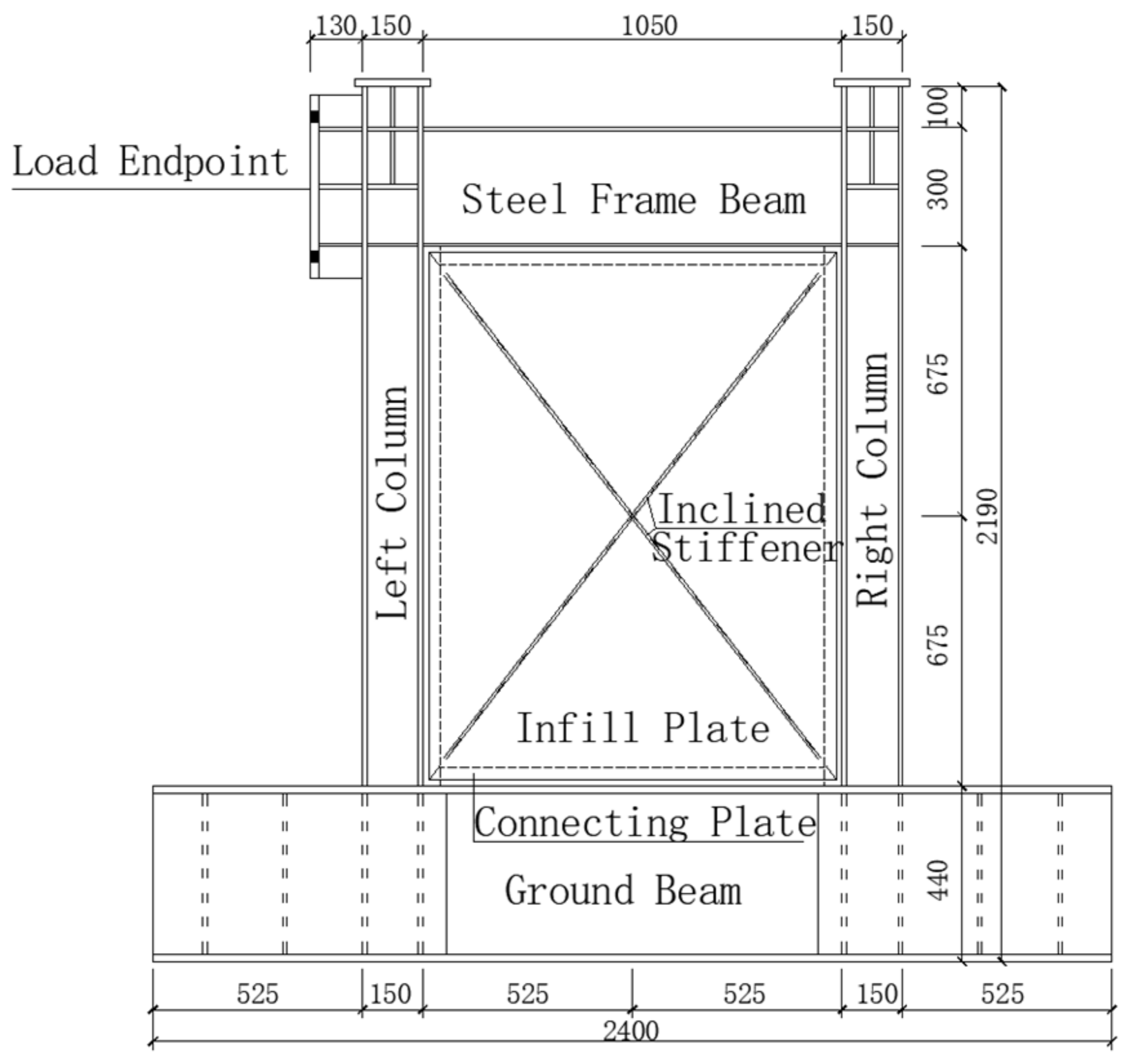
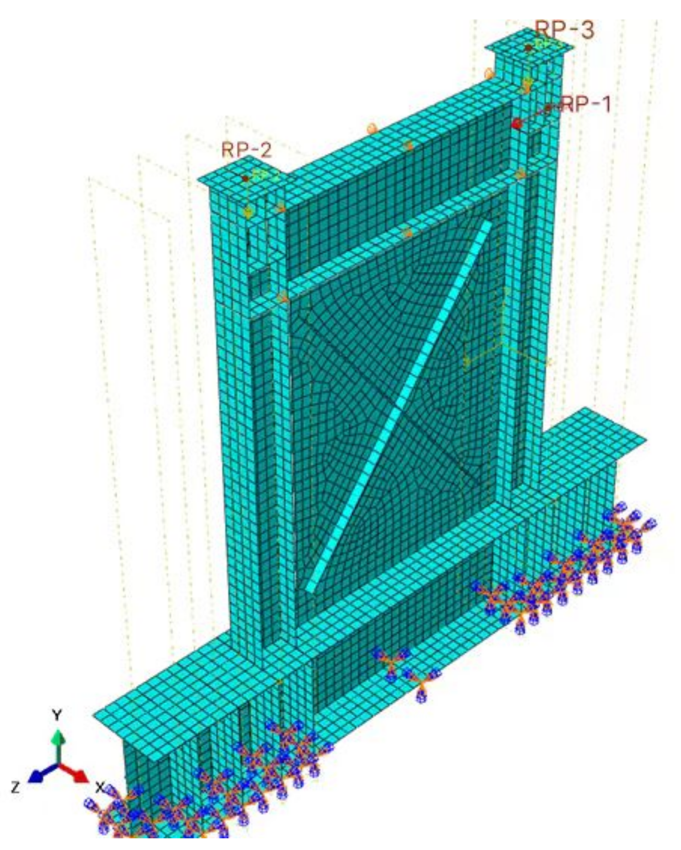
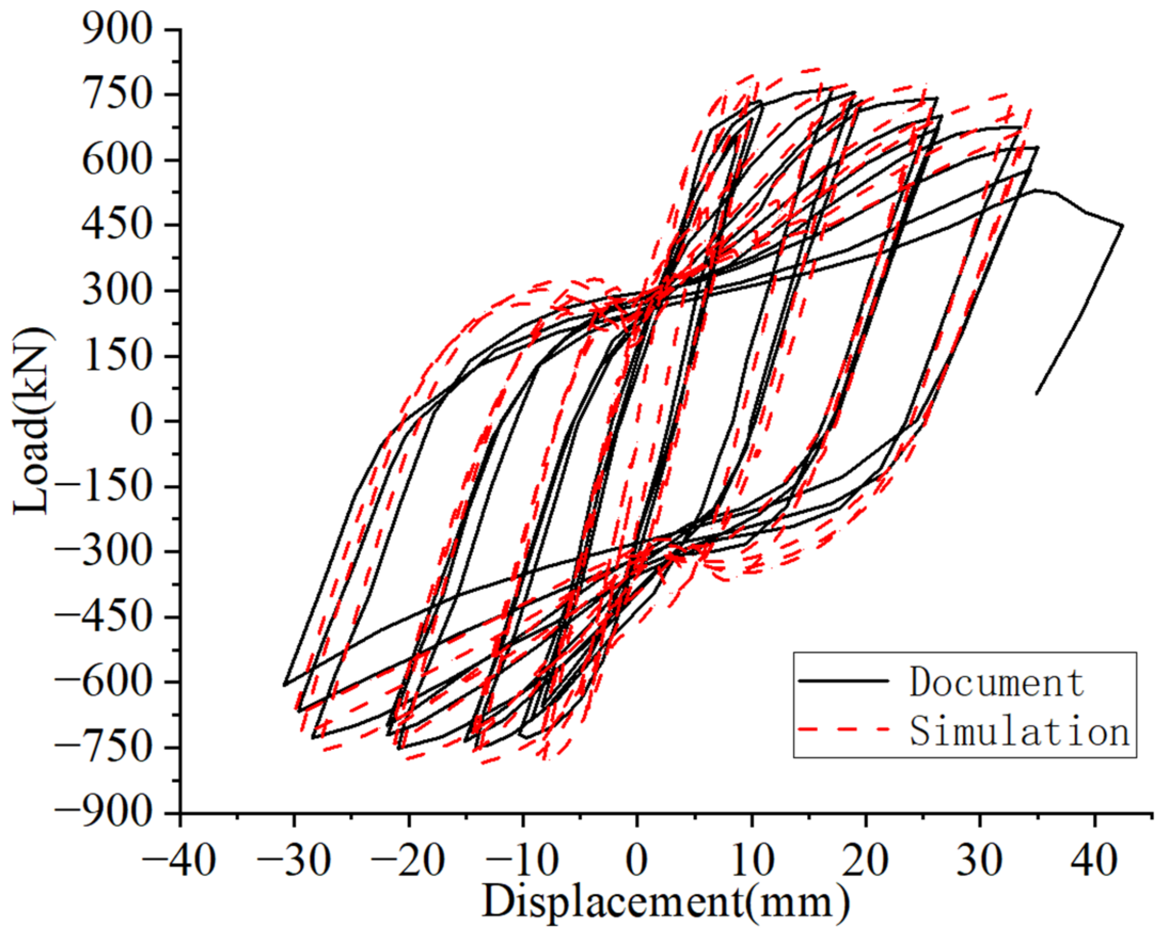
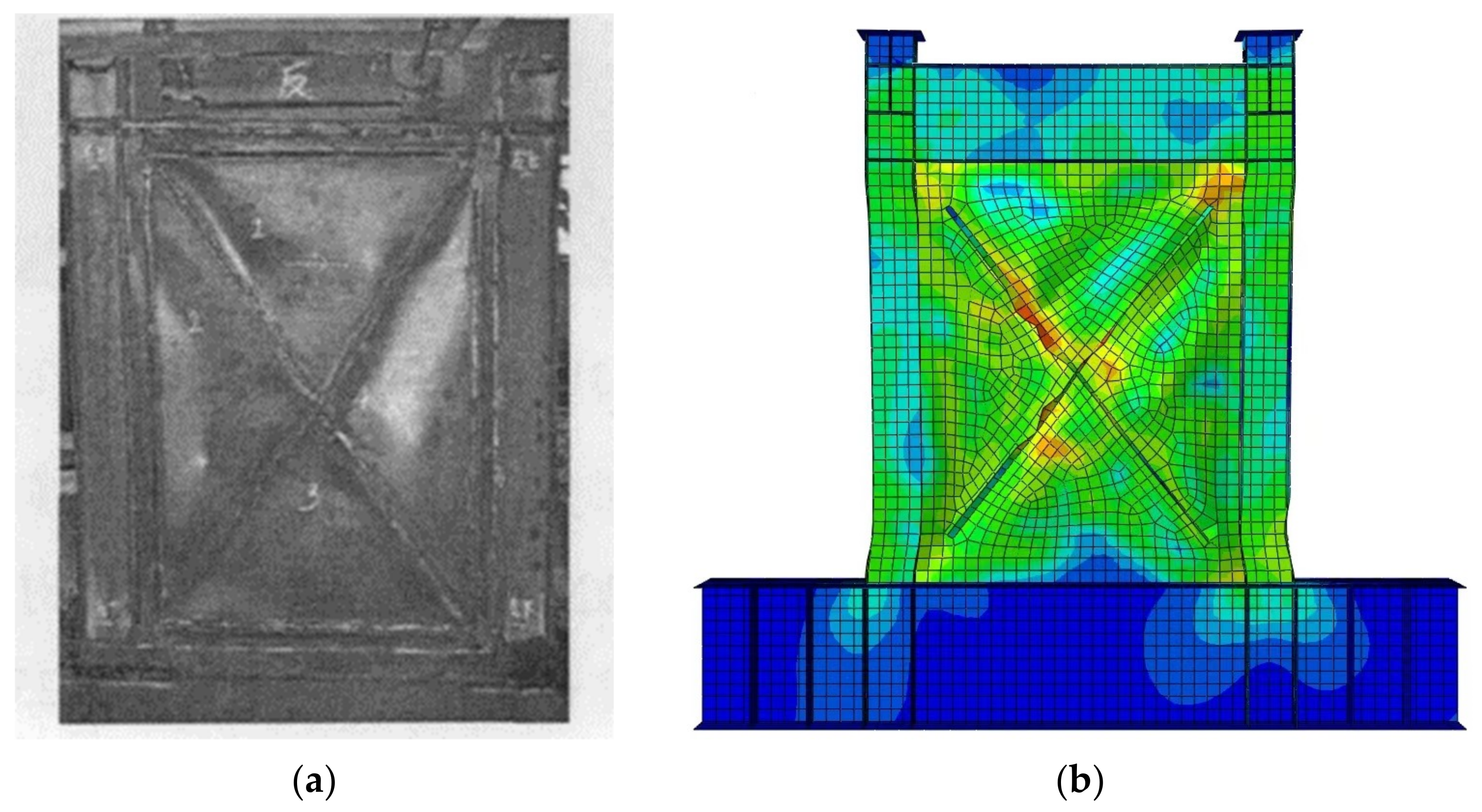
2. Steel Plate Shear Wall Finite Element Model Verification

This study used the inclined stiffened SPSW test scheme for finite element modeling and hysteretic loading analysis proposed by Cao [30]. The literal SPSW size and the dimension of test piece are shown in Figure 1 and Table 1.
In order to make the steel plate play the greatest role in the optimization process, The finite element model did not consider the connection plate. Tie connection was used in the finite element simulation. The connection plate was not set, which can make the steel plate more obvious in the stress process, which was conducive to the optimization of the next. This is the reason why the frame around the panel deforms more in the finite element results. The column and its stiffening ribs were merged into a single unit through a merging method. The stiffening ribs and steel plate were combined into a single unit. The loading end of the left column was not reflected in the finite element model; however, the reference point RP-1 was selected on the right side of the model column (Figure 2). The horizontal load loading history was applied to Uz through the coupling method (Figure 3). Similarly, the vertical load was applied by selecting the reference point RP-2 and RP-3 coupled Uy at the upper end of the left and right columns. The ground beam of the SPSW was fixed to the ground. In this model, the free meshing technique was used for the grid division of the oblique stiffened plate. The grid was generated according to the S4R element. Only a few S3 elements were used when the S4R element cannot be generated at the end of the oblique stiffened plate. The initial defect was introduced into the model according to the amplitude reported by Guan [13] with the first buckling mode. The maximum displacement of the first buckling mode was 0.456218; that is, the maximum displacement in the X direction was 0.45138 m, and the maximum initial defect of the 12 m beam was controlled at 0.012 m. Thus, 0.012/0.45138 = 0.0266; 0.0266 was set as the UPGEOM coefficient.
The constitutive relationship of the SPSW was based on the material test data reported by Cao [30]. The steel used was Q235B. Table 2 lists the test index. The steel stress–strain relationship adopted a trilinear constitutive model. The first section is the elastic stage, the second section is the strengthening section with a tangent stiffness of 0.005E, and the third section is the ideal elastoplastic. The nominal stress–strain relationship was transformed into an actual stress–strain relationship.
The shell element and corresponding material constitutive relationship were used for modeling. Figure 4 compares the simulated hysteresis loading results and test data. Figure 5 compares the failure modes. The overall change in the hysteresis curve was consistent. At the initial stage of loading, the steel plate yielded first, and no apparent local buckling was observed. Plastic deformation was observed on the steel plate far from the loading end, and the stiffener yielded. Subsequently, the SPSW was loaded up to a displacement of 18 mm and gradually returned to the zero displacement. The right column yielded, and no apparent plate buckling deformation and breathing effect were observed. The stiffeners of the SPSW did not break during the cyclic loading process, and buckling and residual deformation were apparent, resulting in the stiffeners continuing to provide the bearing capacity to the steel plate during the pull loading. However, the ultimate load and peak load in the literature were 811.65 kN and 765.7 kN, respectively, error was only 6%. Therefore, using finite element model to simulate the stiffening effect on SPSWs is feasible and acceptable.

3. Steel Plate Shear Wall Stiffener Optimization Design

3.1. Steel Plate Shear Wall Optimization Scheme

Table 3 shows the optimization scheme for the SPSW. The SPSWs with different sizes and vertical loads were set according to the aspect ratio. The infill plate thickness was 5 mm. A constant height of 3000 mm was maintained. Both sides of the plate were optimized with a 5 mm thick stiffener. The height and infill plate were the same at 3000 mm. The height–width ratios were 0.5, 0.75, 1, and 2. The height and width of the SPSWs (mm × mm) were 3000 × 6000, 3000 × 4000, 3000 × 3000, and 3000 × 1500.

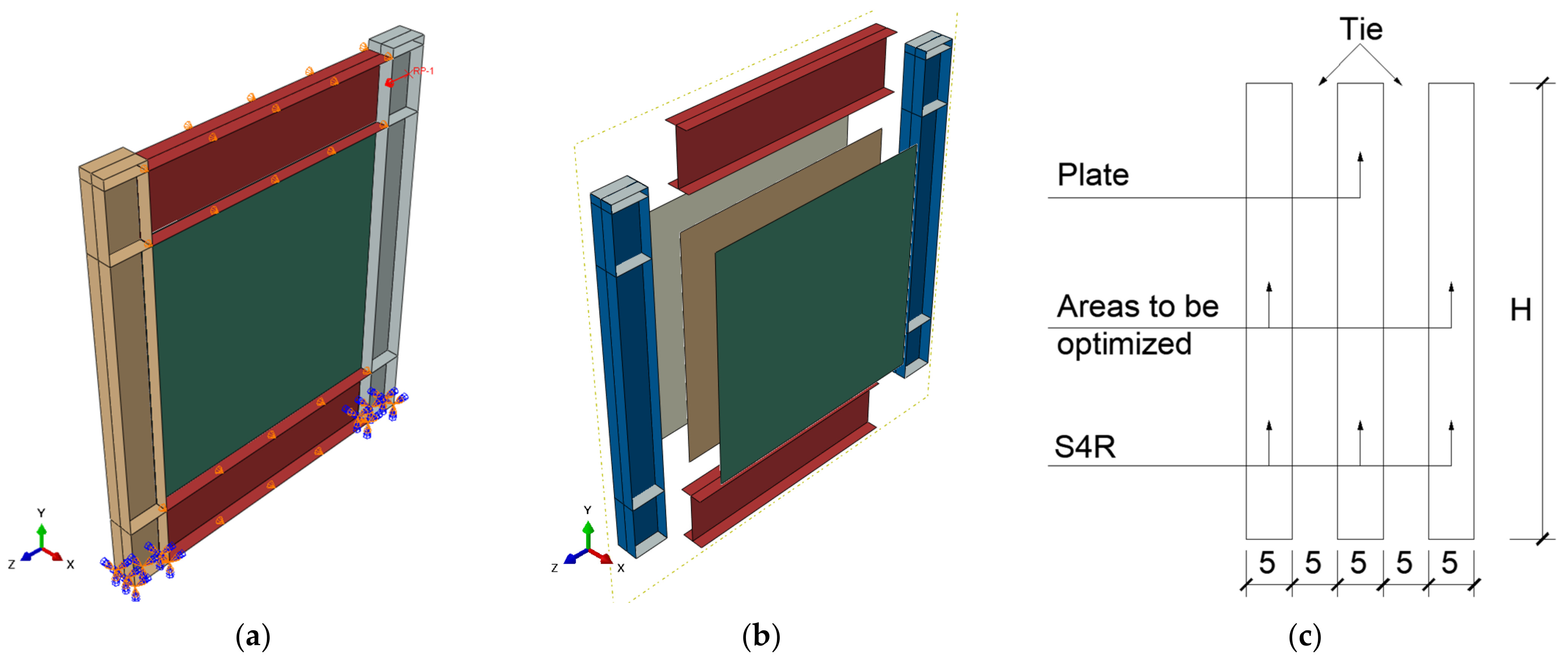
3.2. Finite Element Optimization Model

The stiffeners of the SPSW were symmetrically arranged. The three-layer S4R shell element of the stiffener and plate was used to establish the SPSW with tie constraints. The steel plate was in the middle, with the stiffeners on both sides of the plate. Similar to the sandwich structure (Figure 6), the stiffeners and the steel plates were 5 mm apart in the x direction. The optimized area was connected only to the steel plate and not the surrounding frame. According to the surface–surface tie constraint, a combination of deformable subregions was allowed, whereas a combination of rigid and deformable subregions was not. The shared nodes between the facet and main facet were removed. The shared nodes were not constrained by the face–face equation. The steel plate was connected with the plate in the optimized area by tie, which can make the optimized stiffeners more closely related to the shear wall and was beneficial to the optimization process. The model grid was 40 mm in size. The optimization model did not introduce initial geometric defects because the initial geometric defects of the SPSW were not fixed.

4. Bidirectional Asymptotic Structural Optimization Method for Elastoplastic Analysis

4.1. Mathematical Optimization Model

The SPSW must consider the structural nonlinearity when using the interactive program of Abaqus and bidirectional evolutionary structural optimization method [14] based on Python for the elastic–plastic analysis. The objective function should be changed to the maximum external force work if the maximum stiffness of the SPSW is changed from 0 to the target displacement U* during the displacement loading process of the SPSW. The mathematical model of the bidirectional evolutionary structural optimization algorithm proposed by Huang [3] is shown in Equation (1).
M a x i m i z e   f x = W = lim n 1 2 i = 1 1 U i T U i 1 T F I + F I 1 S u b j e c t   t o   V * e = 1 M V e x e = 0 x e = x m i n   o r   1   e = 1 , , M
where W is the external force work of structure, n is the total number of intervals of the design displacement, F is the external force vector, V* is the prescribed structural volume, Ve is the volume of an individual element, and xe is the relative density of the e-th binary design variable unit. When xe = 1, the unit is not deleted, which is the relative density of the real unit; when xe = xmin, the unit is softly deleted, which is the relative density of the virtual unit, generally 0.001.
The optimization iteration is stopped when the structure of the optimization region satisfies the volume constraint value, and the performance index variation satisfies Equation (2), expressed as follow:
e r r o r = i = 1 N P I k i + 1 P I k N + i 1 i = 1 N P I k i + 1 τ
where PI is the performance index. It can be an objective function, such as external work, average stress, structural frequency, etc., or the reciprocal of the product of the objective function and the volume fraction, which depends on the optimization objective and the actual process of convergence. N generally takes 2–5 integers, τ is the allowable convergence error.
The sensitivity of the elastoplastic optimization algorithm to extract the deletion criterion is the sum of the elastic strain energy and plastic deformation dissipation energy. The optimization convergence criterion is based on Equation (2); however, the PI equation is influenced by the external force work C, and the iterative volume V changes inconsistently. Moreover, achieving the same value in different iterations is challenging. In addition, the forced condition material V reaches the volume constraint value V* before Equation (2). The convergence criterion was judged, and the convergence of Equation (1) was found to be too strict. The convergence residual value τ was slightly enlarged by 0.1%. The convergence criterion (external force work per unit volume) represents the material efficiency. The closer the structural optimization to convergence, the gentler the objective function changes and the faster the material efficiency changes.

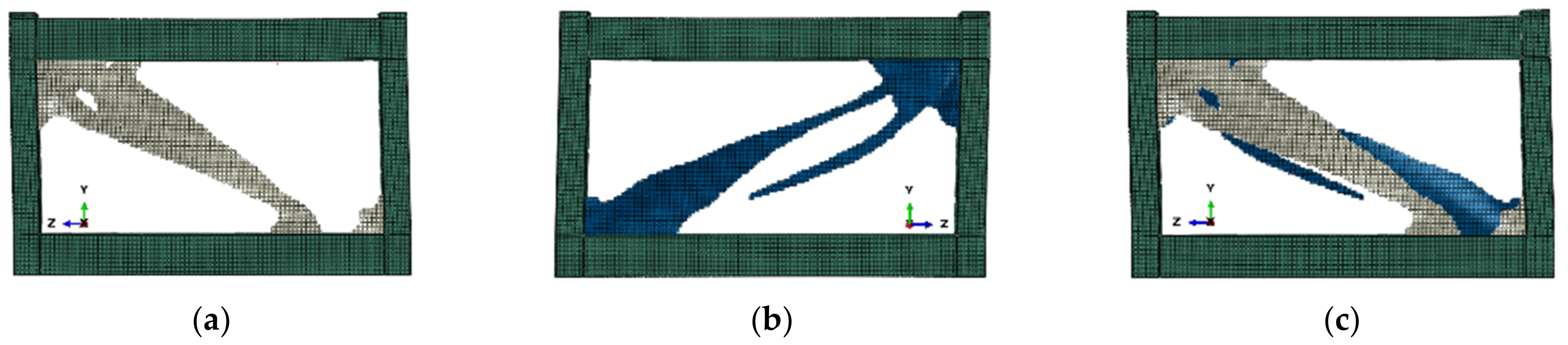
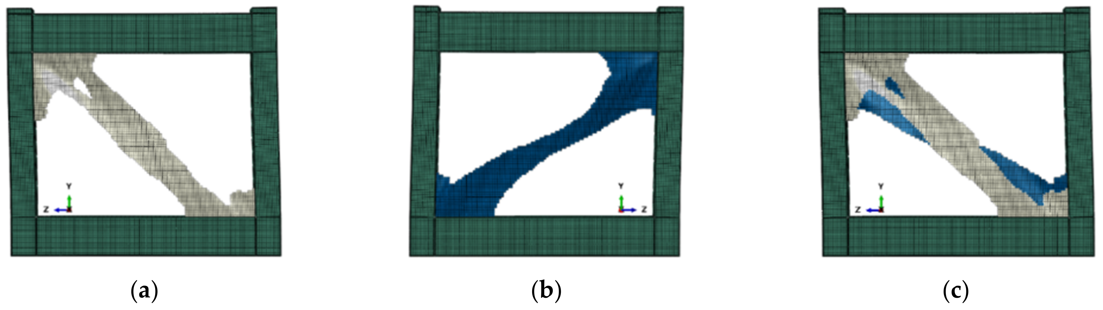
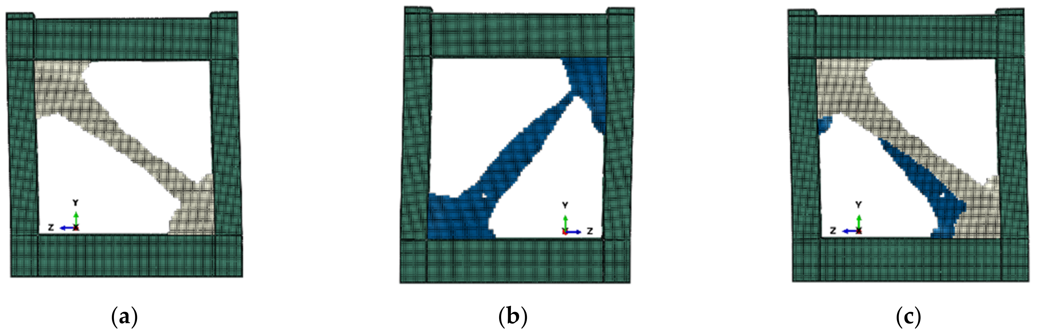
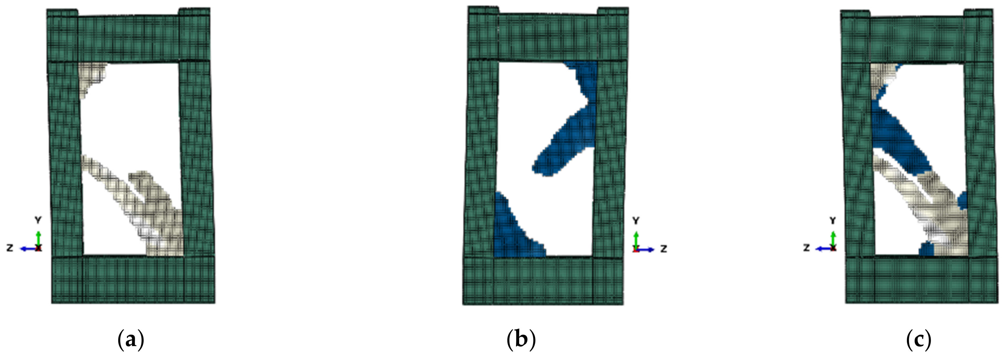
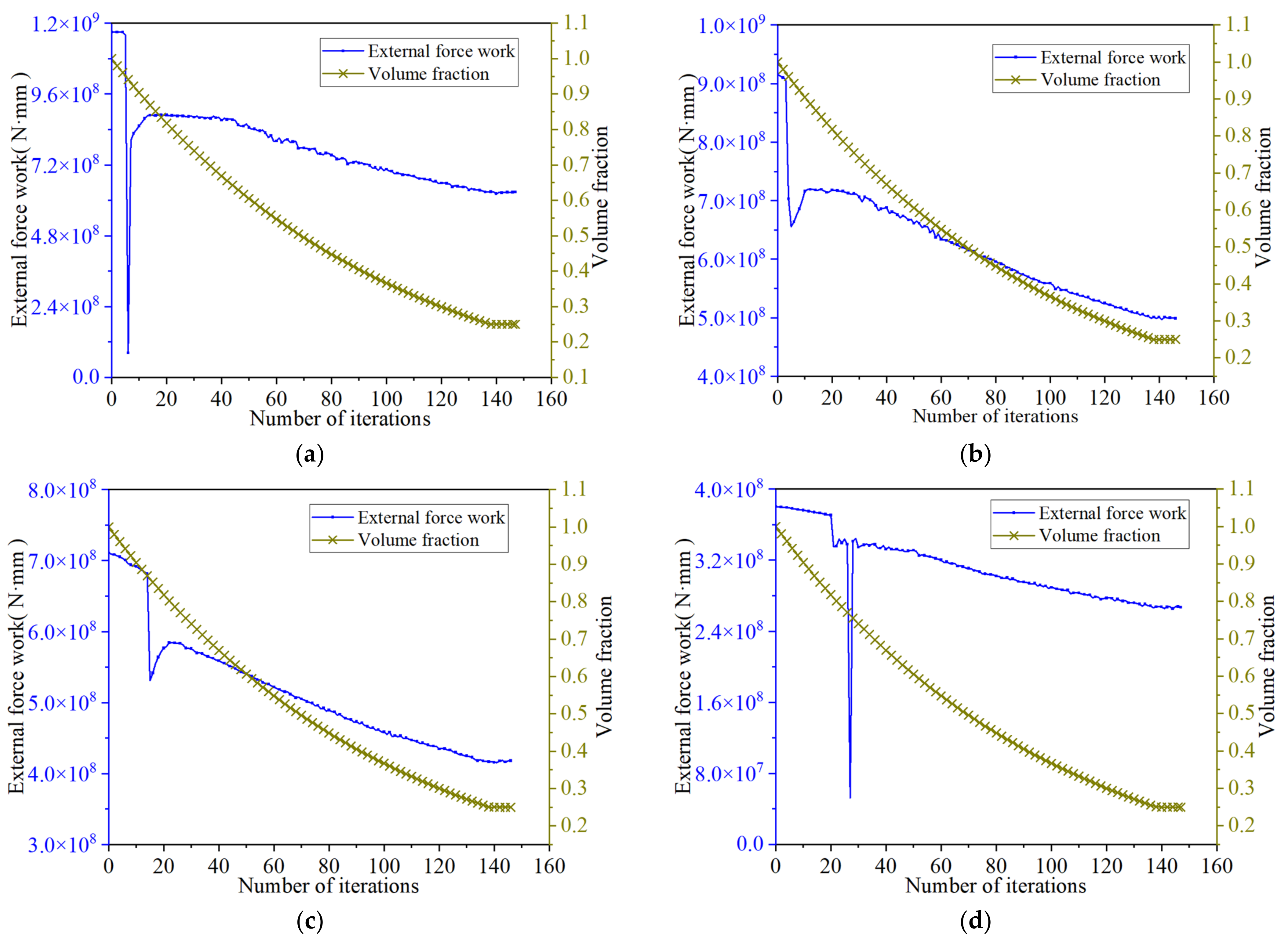
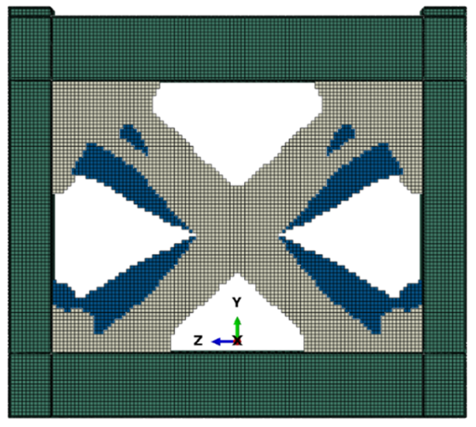
4.2. Optimization Results

An elastic–plastic optimization was performed on four steel plates (SPSW-A0.5, SPSW-A0.75, SPSW-A1.0, and SPAW-A2.0); the number of infill plate elements according to the grid size was designed to be 75 × 150, 75 × 100, 75 × 75, and 75 × 38, respectively. The elastic–plastic analysis optimized the loading inter-story displacement angle to be 1/50, and the positive horizontal loading displacement along the Z axis was 74 mm. Figure 7, Figure 8, Figure 9 and Figure 10 show the optimization results.
The stiffening effect optimization results show that the front and back optimization areas were not symmetrical with the center plane of the infill plate, and the distribution of the stiffening effect of SPSWs with different aspect ratios was similar. The stiffening effect was distributed near the tension band. Figures (c) of Figure 7, Figure 8, Figure 9 and Figure 10 shows that the front stiffening effect was distributed along the convex surface. The stiffening effect of the SPSW extended from the upper left corner to the lower right corner with an increase in the aspect ratio. The negative side was distributed along the diagonal tension band in the front complementary position. There were more stiffening units in the upper left and lower right corners. The stiffening effect was distributed along 135° with the 2.0 aspect ratio, extending from the lower right corner to the middle of the left column. In the optimization history (Figure 11), the stiffening effect was stable when the optimization reached the target volume, and the convergence residual iteration stopped. The initial external force work values of the SPSWs with a height–width ratio of 0.5, 0.75, 1.0, and 2.0 were 1.17 × 10⁹ N∙mm, 9.15 × 10⁸ N∙mm, 7.11 × 10⁸ N∙mm, and 3.80 × 10⁸ N∙mm; the corresponding last generation values were 6.28 × 10⁸ N∙mm, 4.99 × 10⁸ N∙mm, 4.18 × 10⁸ N∙mm, and 2.67 × 10⁸ N∙mm, respectively, 46.28%, 45.53%, 41.17%, and 29.83% lower than the initial values. These results indicate that the stiffening effect of the elastoplastic analysis optimization on SPSW weakened with an increase in the height–width.
When the SPSW is loaded in the elastic–plastic stage, the symmetrical distribution of the stiffening effect will suppress the small out-of-plane deformation of the steel plate; the unit strain energy and deformation will differ. However, the optimization process did not limit the symmetrical distribution of stiffeners. The asymmetric stiffeners will aggravate the out-of-plane deformation of the shear wall and lead to the generation of tension bands, which was finally reflected in the transition of external force work between different generations.

5. Performance Analysis of Steel Plate Shear Wall Structure after Optimization

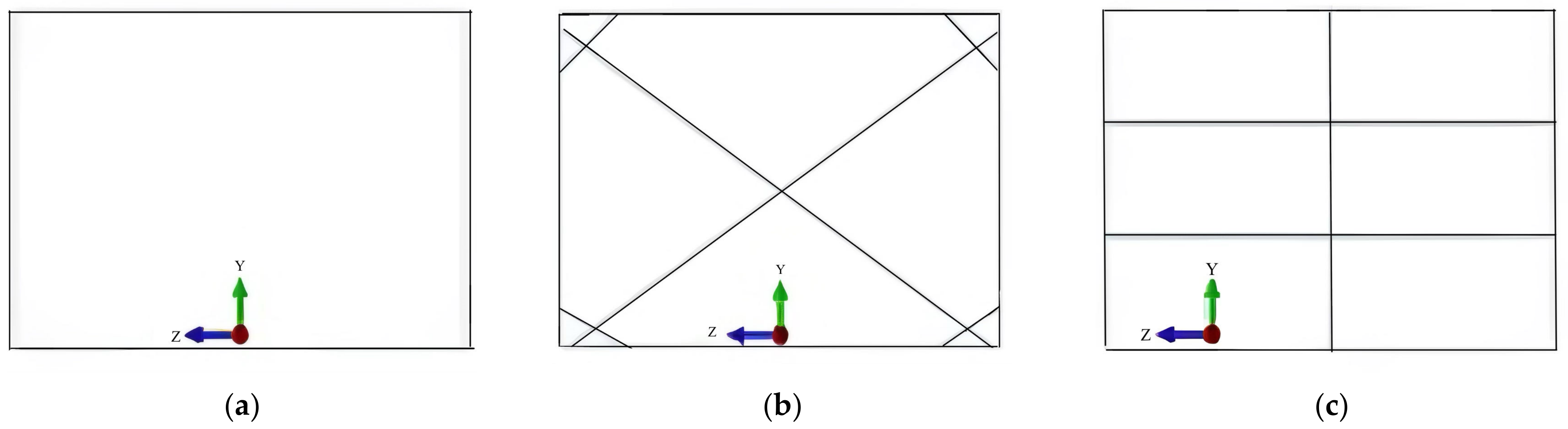
5.1. Different Stiffener forms of Optimized Steel Plate Shear Wall

The SPSW was subjected to unidirectional loading during the optimization process based on the bidirectional asymptotic structural optimization method. The actual working condition was random in the force direction, and the force was transmitted from all directions. As shown in Figure 12, the symmetrical arrangement of the steel plates along the in-plane direction should be considered in setting the stiffeners. The elastic–plastic optimization analysis shows that the stiffeners were obliquely crossed; thus, the stiffeners of the SPSW should strengthen the corner locally.
Figure 13 shows the arrangement of the stiffeners. Different forms of single plate stiffeners were arranged according to the distribution law of stiffeners after SPSW optimization. The section size was 100 × 10 mm, and the inclined angles of the stiffeners were 35.9° and 144.1°, 46.3° and 133.7°. No stiffening was set for the SPSW-A075 according to its optimization results and structural dimensions. The symmetrical stiffeners for the A075-P were set according to the stiffener distribution optimized by elastoplastic analysis. Common transverse and longitudinal stiffeners (two transverse and one vertical stiffener) were set for the A075-HV.

5.2. Monotonic Loading Simulation Numerical Test of Stiffened Steel Plate Shear Wall after Optimization

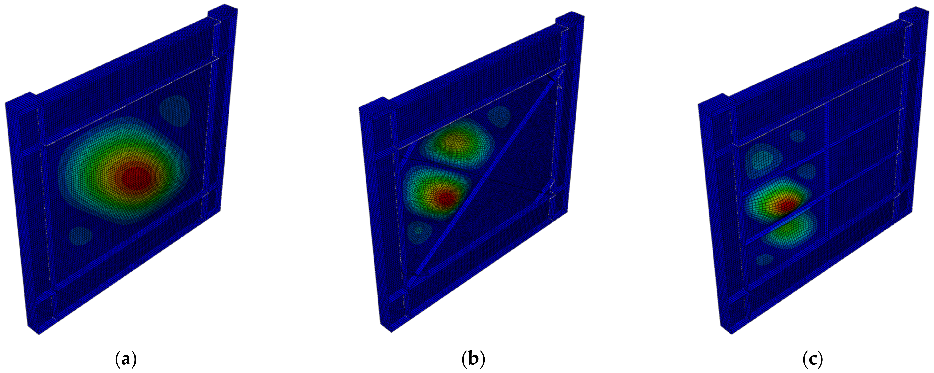
5.2.1. Elastic Buckling Analysis

The A075 was an unstiffened SPSW. The buckling mode was overall buckling, and the overall direction was approximately 144.1°. Local buckling occurred at the upper left part of A075-P. Setting the transverse and longitudinal stiffeners in A075-HV made the steel plate area smaller and caused buckling in the left steel plate. Table 4 shows the buckling load of the unstiffened SPSW, which was approximately 133.50 kN. The SPSW can improve the buckling bearing capacity through the stiffening arrangement; however, the buckling loads of SPSWs with different stiffener arrangements increase in varying degrees. Figure 14 shows that the buckling load of the symmetrical stiffener A075-P increased significantly; the increase was 2.17–2.61 times. The maximum increase (five times) in buckling load was observed in the A075-HV SPSW. The number of grids obtained by dividing the SPSW wall by the infill panel primarily caused the difference in buckling load. The single stiffener was divided into two grids, the oblique symmetrical stiffener was divided into four grids, but the transverse and longitudinal stiffeners were divided into nine grids.

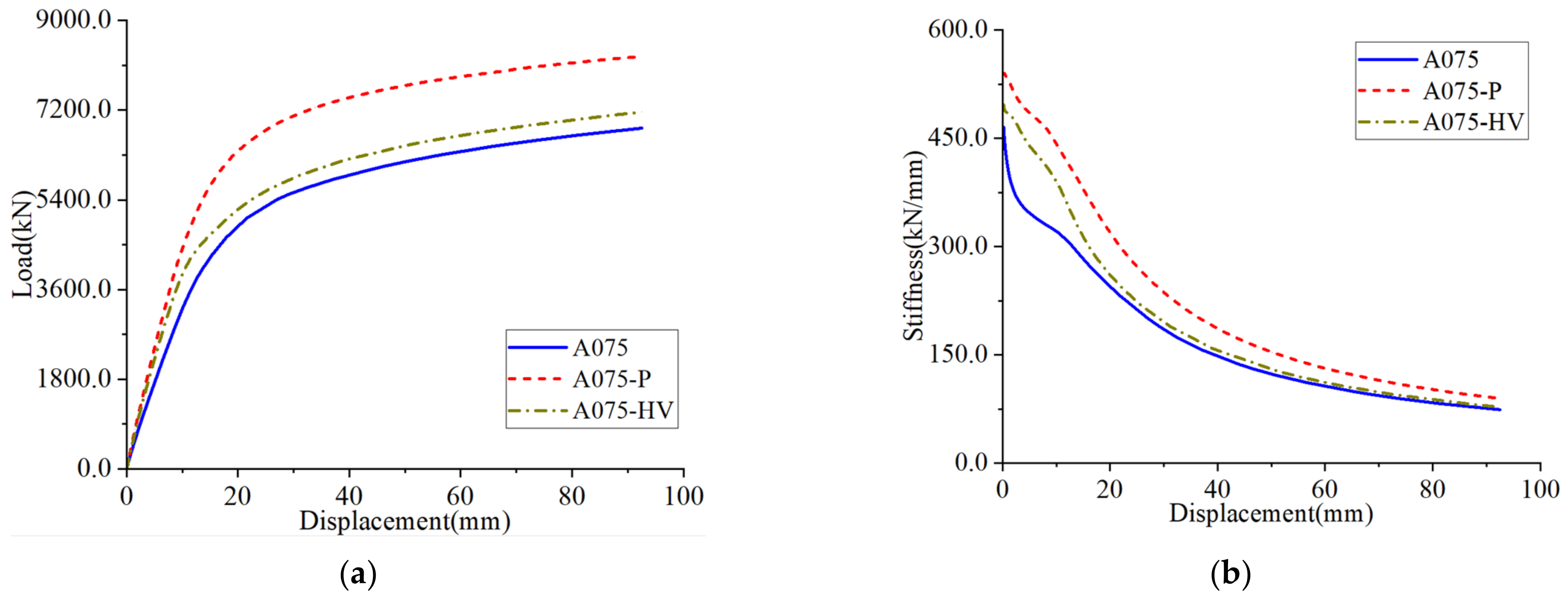
5.2.2. Steel Plate Shear Wall Bearing Capacity and Stiffness

Figure 15 shows the monotonic loading load–displacement and stiffness–displacement curves of the SPSW. The bearing capacity and stiffness of the stiffened SPSW were greater than those of the unstiffened SPSW A075 and transverse and longitudinal stiffened SPSW A075-HV. This indicates that the transverse and longitudinal stiffened SPSW contributed little to the stiffness and ultimate bearing capacity. The stiffeners of A075-P were arranged according to the elastoplastic optimization results. The diagonal stiffeners improved the initial stiffness of the SPSW. Moreover, the ultimate bearing capacity of A075-P was high, inferring that the stiffener arrangement angle in A075-P is the best for elastoplastic optimization. The four angles of the steel plate and frame connection were stiffened locally, resulting in a slightly higher ultimate bearing capacity.

5.3. Numerical Simulation Test on Cyclic Loading of Stiffened Steel Plate Shear Wall after Optimization

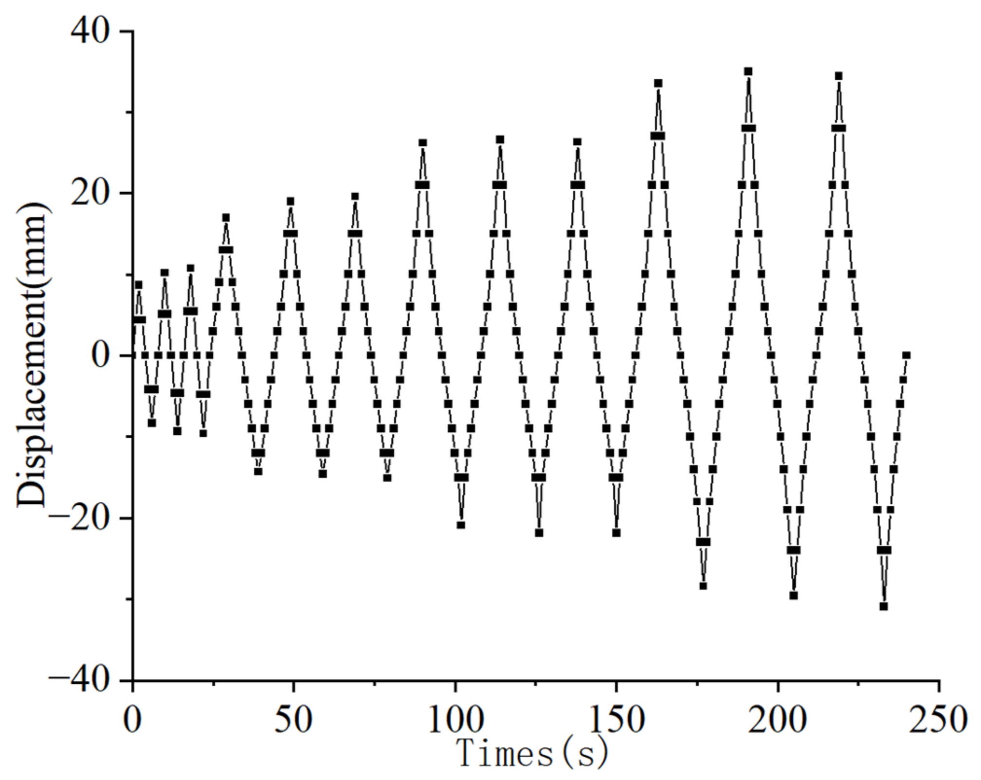
5.3.1. Loading System

A cyclic loading numerical simulation test of the SPSW was performed to analyze its energy dissipation capacity. The maximum displacement angle of the SPSW loading system was 0.025. Table 5 shows the loading system parameters.

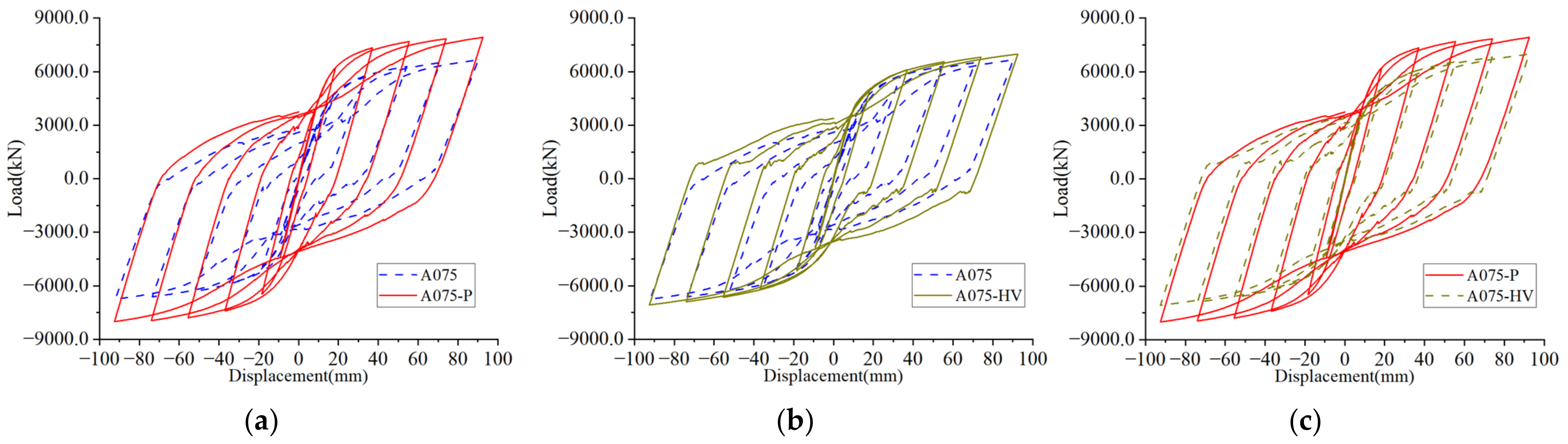
5.3.2. Hysteresis Performance

The hysteretic behaviors of the unstiffened and stiffened SPSW were compared and analyzed. According to the hysteretic curve (Figure 16), the load–displacement curves of the unstiffened and stiffened SPSWs were consistent.
A comparison of A075-P with A075 and A075-HV shows that the hysteretic area of A075-P was larger than that of A075 and A075-HV. Moreover, the load of A075-P was larger than that of A075 and A075-HV when each cycle was loaded to the target displacement, significantly delaying the shear performance degradation of the steel plate in the zero-stress area. Furthermore, the arrangement of stiffeners and tension bands in the same direction improved the structural stiffness of the SPSW. The stiffness of A075 first weakened during the reaction force conversion. The shape of the hysteresis curve was a “bow”, indicating that the hysteresis curve was affected by a slip. The hysteresis curve of A075-P was fuller than those of A075 and A075-HV. This indicates that A075-P has good seismic performance and energy dissipation capacity and can reduce noise and improve comfort significantly. A comparison of the A075-HV and A075 loading curves shows that the shear performance degradation of steel plate was inhibited when unloaded to zero reaction. The effect of the transverse and longitudinal stiffeners on the maximum stiffness of the structure was not apparent.

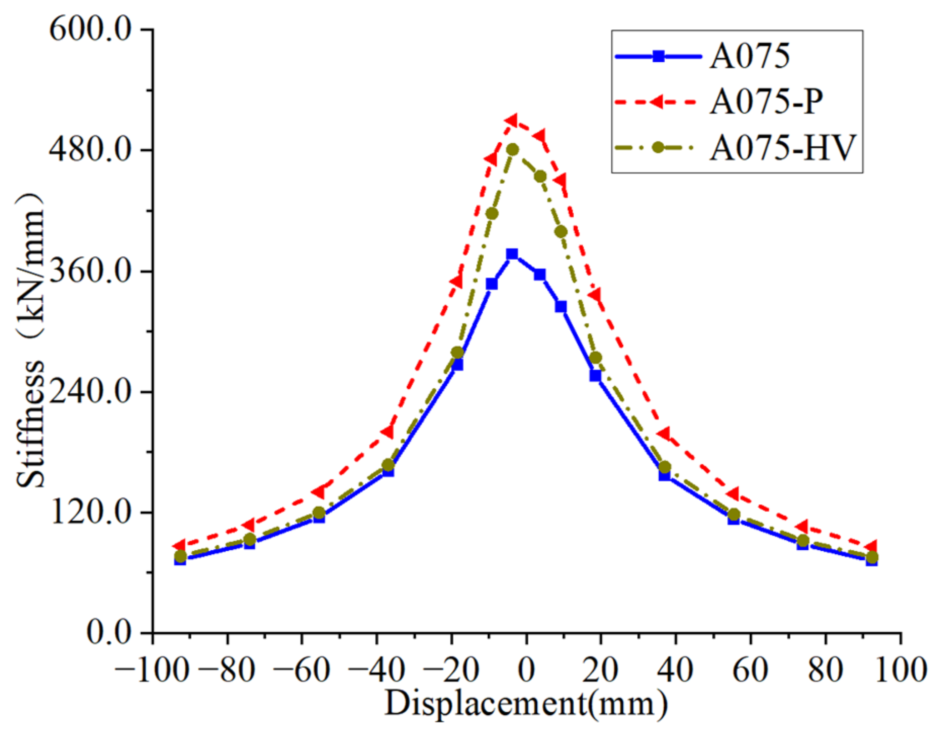
5.3.3. Stiffness Degradation

Figure 17 shows the stiffness degradation of the SPSW wall under cyclic loading. The stiffness of the structure gradually decreased with an increase in the loading displacement, and the stiffness degradation of the stiffened SPSW was rapid in the later stage. When the structure was loaded to the elastic–plastic stage, the stiffness of the obliquely stiffened SPSW A075-P was greater than that of the unstiffened SPSW A075 and transverse and longitudinal stiffened SPSW A075-HV. This indicates that the oblique stiffening contributed to the structural stiffness in the elastic–plastic stage and inhibited the weakening of the steel plate stiffness. By contrast, the transverse and longitudinal stiffeners were unsuitable for the plastic stage design of the SPSW.

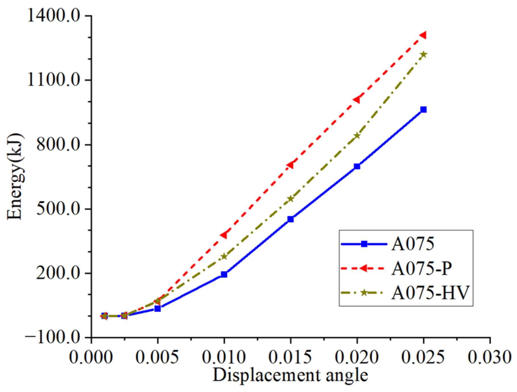
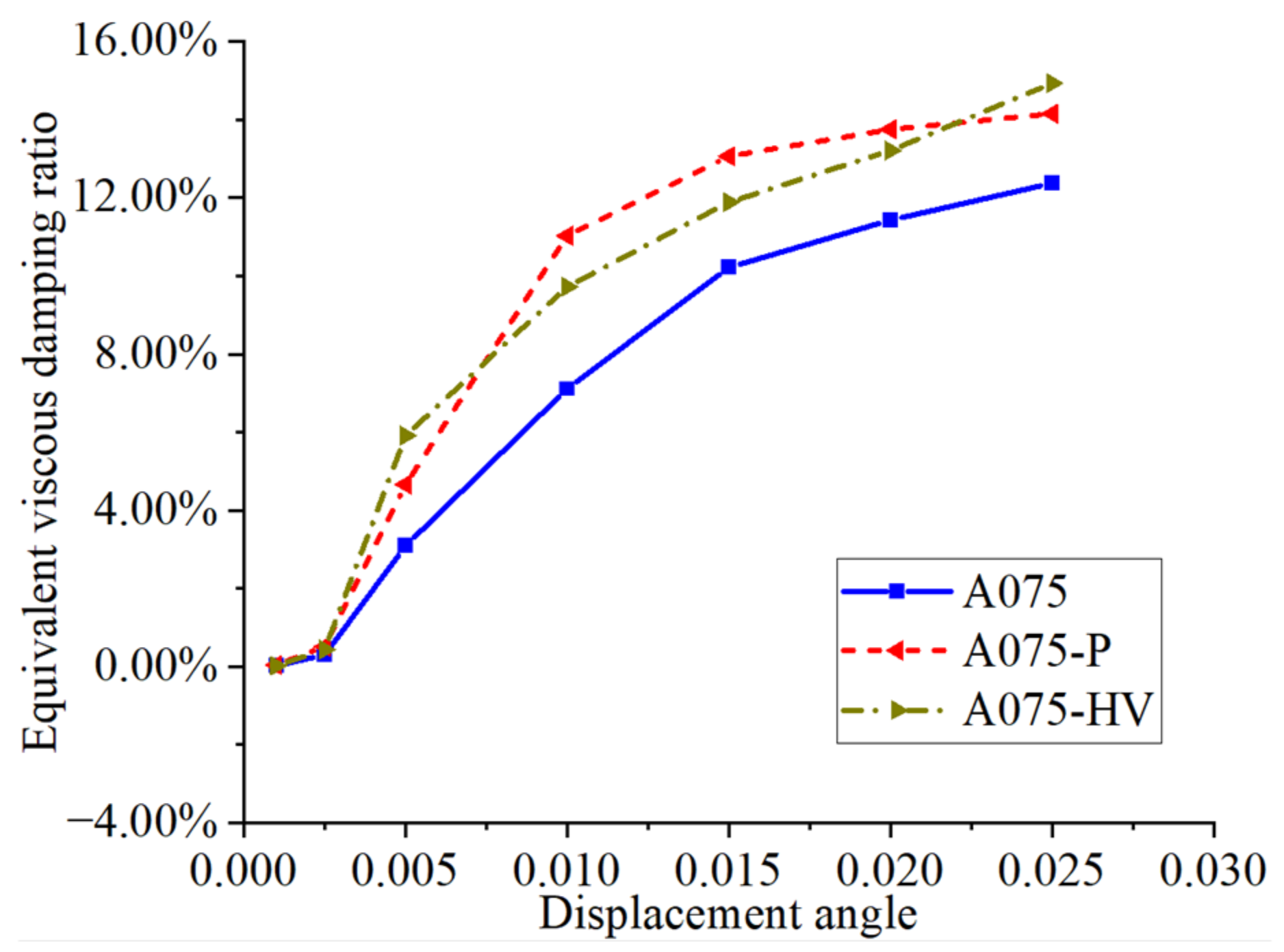
5.3.4. Energy Dissipation Performance

As shown in Figure 18 and Figure 19, the energy dissipation and equivalent viscous damping ratio of the stiffened SPSW under cyclic loading were greater than those of the unstiffened SPSW. The hysteresis loop area of each cycle increased proportionally after the structure was loaded to a 0.005 inter-story displacement angle. The energy consumption of A075-P was higher than that of A075 and A075-HV. During the loading process, the overall stiffness of A075-HV was smaller than that of A075-P, and the local buckling occurred before A075-P and the stiffener began to play a role. Therefore, the absorbed energy was slightly larger than that of A075-P in the early stage. Conversion of equivalent viscous damping ratio based on hysteresis curve, at the beginning of loading, the equivalent viscous damping ratio of A075-P was not always higher than that of A075 HV. In conclusion, the energy dissipation performance of the SPSW based on the optimal arrangement of stiffeners in the bidirectional progressive structure was better.

6. Discussion

An SPSW has excellent elastic–plastic performance and energy dissipation performance. It is a very promising lateral force-resisting structural system [8,9,10]. The SPSW can be divided into thick SPSW and thin SPSW according to the height-thickness ratio. In the lateral force-resisting system of high-rise steel structure buildings, the thin SPSW is an efficient and economical lateral force-resisting system compared with a thick steel plate shear wall. The post-buckling capacity of the thin SPSW can be utilized when it works. Many studies have shown that thin SPSWs need to be equipped with stiffeners to increase the buckling load [13], but the optimization of stiffeners needs further exploration. There are several future avenues to be studied as follows:
  • Bidirectional evolutionary structural optimization is widely used in structural optimization design [1,2,3,4,5,6,7], but was rarely used in the optimization of SPSW structure. In this article, the bidirectional evolutionary structural optimization algorithm was used to optimize the stiffeners of SPSW, and good results were obtained;
  • Since the application of the steel plate shear wall, the performance of SPSW was analyzed [12,13,14,15,16,17,18]. It was verified that the SPSW needs stiffeners [13,14,18]. However, there is still a lack of research on the optimization of stiffeners;
  • The structural performance of SPSW is affected by aspect ratio [13,31], column stiffness [23,32], beam stiffness [33], etc. In the process of optimization analysis of SPSW, the sensitivity analysis of these influencing factors is still lacking, which can be further explored;
  • Various types of SPSWs have been proposed [34,35,36], but whether their shape and size are the most suitable has not been further verified. The proposed SPSWs can be further optimized.

7. Conclusions

This study established a finite element model of SPSWs using Abaqus based on the bidirectional progressive structural optimization method to optimize the SPSW stiffener. The stiffened SPSW was set up according to the optimization results, and the performance was analyzed by monotonic and cyclic loading. The conclusions are as follows:
  • The improved bidirectional evolutionary structural optimization algorithm combined with Abaqus can be used for multiregion optimization to increase the optimization flexibility;
  • The buckling bearing capacity of stiffened SPSW increased by 2.17–2.6 times based on the bidirectional progressive structural optimization method;
  • Compared with those of unstiffened SPSW and commonly used transverse and longitudinal stiffened SPSW, the stiffness and initial stiffness of stiffened SPSWs optimized through the bidirectional evolutionary structural optimization method improved significantly;
  • The hysteresis curve of stiffened SPSW optimized through the bidirectional evolutionary structural optimization method was fuller, indicating a good seismic performance and energy dissipation capacity. Moreover, the optimized stiffened SPSW can reduce noise and improve comfort significantly.

Author Contributions

Methodology, J.H., S.C. and H.X.; software, X.L. and H.X.; resources, J.H.; data curation, J.H.; writing—original draft preparation, H.X.; writing—review and editing, X.L.; supervision, S.C.; funding acquisition, J.H. and S.C. All authors have read and agreed to the published version of the manuscript.

Funding

Study on energy dissipation capacity of joints in steel structure system based on modified component method (No. 51708226); Research on some key scientific problems of connection node information in high performance building structures (No. 51638009); Research on constitutive model of steel structure joint based on data analysis and artificial intelligence (No. 51808357).

Data Availability Statement

All data, models, and code generated or used during the study appear in the published article.

Conflicts of Interest

The authors declare no conflict of interest.

References

  1. Xie, Y.; Steven, G. A simple evolutionary procedure for structural optimization. Comput. Struct. 1993, 49, 885–896. [Google Scholar] [CrossRef]
  2. Huang, X.; Xie, Y. Topology optimization of nonlinear structures under displacement loading. Eng. Struct. 2008, 30, 2057–2068. [Google Scholar] [CrossRef]
  3. Huang, X.; Xie, Y.M. Evolutionary Topology Optimization of Continuum Structures: Methods and Applications; Wiley: Hoboken, NJ, USA, 2010. [Google Scholar] [CrossRef]
  4. Huang, X.; Xie, Y. Convergent and mesh-independent solutions for the bi-directional evolutionary structural optimization method. Finite Elements Anal. Des. 2007, 43, 1039–1049. [Google Scholar] [CrossRef]
  5. Zhou, M.; Shyy, Y.K.; Thomas, H.L. Checkerboard and minimum member size control in topology optimization. Struct. Multidiscip. Optim. 2001, 21, 152–158. [Google Scholar] [CrossRef]
  6. Zuo, Z.H.; Xie, Y.M. A simple and compact Python code for complex 3D topology optimization. Adv. Eng. Softw. 2015, 85, 1–11. [Google Scholar] [CrossRef]
  7. Sigmund, O.; Petersson, J. Numerical instabilities in topology optimization: A survey on procedures dealing with checkerboards, mesh-dependencies and local minima. Struct. Optim. 1998, 16, 68–75. [Google Scholar] [CrossRef]
  8. Chen, G.; Guo, Y.; Fan, Z.; Han, Y. Cyclic test of steel plate shear walls. J. Build. Struct. 2004, 25, 19–25. [Google Scholar] [CrossRef]
  9. Guo, Y.-l.; Zhu, J.-s. Research progress of shear walls: Types and design methods. Eng. Mech. 2020, 37, 19–33. [Google Scholar] [CrossRef]
  10. Guo, Y.L.; Dong, Q.L. Static behavior of buckling-restrained steel plate shear walls. Tall Build. 2005, 666–670. [Google Scholar] [CrossRef]
  11. CAN/CSA-S16.1-94, Limit States Design of Steel Structures. S. 1995-04-01. CSA PLUS 4001-95.
  12. Takahashi, Y.; Takemoto, Y.; Takeda, T. Experimental study on thin steel shear walls and particular bracings under alternative horizontal load. Br. J. Anaesth. 1973, 185–191. [Google Scholar]
  13. Formisano, A.; Mazzolani, F.M.; Matteis, G.D. Numerical analysis of slender steel shear panels for assessing design formulas. Int. J. Struct. Stab. Dyn. 2007, 7, 273–294. [Google Scholar] [CrossRef]
  14. Sabouri-Ghomi, S.; Sajjadi, S.R.A. Experimental and theoretical studies of steel shear walls with and without stiffeners. J. Constr. Steel Res. 2012, 75, 152–159. [Google Scholar] [CrossRef]
  15. Lv, Y.; Li, Z.-X.; Lu, G. Shear capacity prediction of steel plate shear walls with precompression from columns. Struct. Des. Tall Spéc. Build. 2017, 26, e1375. [Google Scholar] [CrossRef]
  16. Jin, S.; Xie, Y.; Li, M.; Bai, J. Seismic performance quantification of buckling-restrained steel plate shear wall-RC frame structures. J. Build. Eng. 2022, 58, 104992. [Google Scholar] [CrossRef]
  17. Hajimirsadeghi, M.R.; Fanaie, N. Steel plate shear walls with large disconnected lengths of web plate to vertical boundary element. Structures 2021, 34, 4596–4615. [Google Scholar] [CrossRef]
  18. Xu, Z.; Tong, G.; Zhang, L. Design of horizontal stiffeners for stiffened steel plate walls in compression. Thin-Walled Struct. 2018, 132, 385–397. [Google Scholar] [CrossRef]
  19. Durvasula, S.; Nair, E.S. Buckling of Simply Supported Skew Plates. J. Eng. Mech. Div. 1971, 97. [Google Scholar] [CrossRef]
  20. Wittrick, H.W. Buckling of Oblique Plates with Clamped Edges under Uniform Compression. Aeronaut. Q. 2016, 4, 151–163. [Google Scholar] [CrossRef]
  21. Mizusawa, T.; Leonard, J. Vibration and buckling of plates with mixed boundary conditions. Eng. Struct. 1990, 12, 285–290. [Google Scholar] [CrossRef]
  22. Mitsui, K.; Ikarashi, K. Elastic Shear Buckling Coefficients for Oblique Plates. Math. Probl. Eng. 2022, 2022, 9532380. [Google Scholar] [CrossRef]
  23. Qu, B.; Guo, X.; Chi, H.; Pollino, M. Probabilistic evaluation of effect of column stiffness on seismic performance of steel plate shear walls. Eng. Struct. 2012, 43, 169–179. [Google Scholar] [CrossRef]
  24. Gholizadeh, S.; Shahrezaei, A.M. Optimal placement of steel plate shear walls for steel frames by bat algorithm. Struct. Des. Tall Spéc. Build. 2015, 24, 1–18. [Google Scholar] [CrossRef]
  25. Vu, Q.-V.; Papazafeiropoulos, G.; Graciano, C.; Kim, S.-E. Optimum linear buckling analysis of longitudinally multi-stiffened steel plates subjected to combined bending and shear. Thin-Walled Struct. 2018, 136, 235–245. [Google Scholar] [CrossRef]
  26. Guan, S. Topology Optimization Design of Stiffeners for Perforated Steel Plate Shear Walls; Guangdong University of Technology: Guangzhou, China, 2018. [Google Scholar]
  27. Dong, X.; Ding, X.; Li, G.; Lewis, G.P. Stiffener layout optimization of plate and shell structures for buckling problem by adaptive growth method. Struct. Multidiscip. Optim. 2020, 61, 301–318. [Google Scholar] [CrossRef]
  28. Liu, T.; Sun, G.; Fang, J.; Zhang, J.; Li, Q. Topographical design of stiffener layout for plates against blast loading using a modified ant colony optimization algorithm. Struct. Multidiscip. Optim. 2019, 59, 335–350. [Google Scholar] [CrossRef]
  29. Daryan, A.S.; Salari, M.; Palizi, S.; Farhoudi, N. Size and layout optimum design of frames with steel plate shear walls by metaheuristic optimization algorithms. Structures 2023, 48, 657–668. [Google Scholar] [CrossRef]
  30. Cao, C. Research on the Performance of Inclined Stiffened Steel Plate Shear Wall; Xi’an University of Architecture and Technology: Xi’an, China, 2008. [Google Scholar]
  31. Li, C.H.; Tsai, K.C.; Lin, C.H.; Chen, P.C. Cyclic tests of four two-story narrow steel plate shear walls. Part 2: Experimental results and design implications. Earthq. Eng. Struct. Dyn. 2010, 39, 801–826. [Google Scholar] [CrossRef]
  32. Li, C.-H.; Tsai, K.-C.; Su, L.; Lin, P.-C.; Lin, T.-H. Experimental investigations on seismic behavior and design of bottom vertical boundary elements in multi-story steel plate shear walls. Earthq. Eng. Struct. Dyn. 2018, 47, 2777–2801. [Google Scholar] [CrossRef]
  33. Dubina, D.; Dinu, F. Experimental evaluation of dual frame structures with thin-walled steel panels. Thin-Walled Struct. 2014, 78, 57–69. [Google Scholar] [CrossRef]
  34. Zhao, Q.; Qiu, J.; Li, Y.; Yu, C. Lateral behavior and PFI model of sinusoidal corrugated steel plate shear walls. J. Constr. Steel Res. 2023, 203, 107812. [Google Scholar] [CrossRef]
  35. Sun, H.-J.; Guo, Y.-L.; Wen, C.-B.; Zuo, J.-Q. Local and global buckling prevention design of corrugated steel plate shear walls. J. Build. Eng. 2023, 68, 2352–7102. [Google Scholar] [CrossRef]
  36. Dou, C.; Xie, C.; Wang, Y.; Yang, N. Cyclic loading test and lateral resistant behavior of flat-corrugated steel plate shear walls. J. Build. Eng. 2023, 66, 2352–7102. [Google Scholar] [CrossRef]
Figure 1. Literal SPSW size.
Buildings 13 00831 g001
Figure 2. Finite element model of SPSW.
Buildings 13 00831 g002
Figure 3. Cyclic horizontal displacement loading system.
Buildings 13 00831 g003
Figure 4. Hysteretic loading comparison.
Buildings 13 00831 g004
Figure 5. Comparison of failure modes of SPSWs. (a) Failure mode of test. (b) Failure mode of model.
Buildings 13 00831 g005
Figure 6. Finite element optimization model of SPSW. (a) Integral model of SPSW. (b) Explosion diagram of SPSW model. (c) Sandwich plate structure.
Buildings 13 00831 g006
Figure 7. Nonlinear optimization results of SPSW with an aspect ratio of 0.5. (a) Front side. (b) Reverse side. (c) Distribution of stiffening effect.
Buildings 13 00831 g007
Figure 8. Nonlinear optimization results of SPSW with an aspect ratio of 0.75. (a) Front side. (b) Reverse side. (c) Distribution of stiffening effect.
Buildings 13 00831 g008
Figure 9. Nonlinear optimization results of SPSW with an aspect ratio of 1.0. (a) Front side (b) Reverse side. (c) Distribution of stiffening effect.
Buildings 13 00831 g009
Figure 10. Nonlinear optimization results of SPSW with an aspect ratio of 2.0. (a) Front side. (b) Reverse side. (c) Distribution of stiffening effect.
Buildings 13 00831 g010
Figure 11. Iterative results of external force work and volume fraction of nonlinear optimization SPSW. (a) Aspect ratio of 0.5 (b) Aspect ratio of 0.75 (c) Aspect ratio of 1.0; (d) Aspect ratio of 2.0.
Buildings 13 00831 g011
Figure 12. Symmetric distribution of stiffeners.
Buildings 13 00831 g012
Figure 13. SPSW stiffener arrangement. (a) A075. (b) A075-P. (c) A075-HV.
Buildings 13 00831 g013
Figure 14. Buckling mode diagram of SPSW. (a) A075. (b) A075-P. (c) A075-HV.
Buildings 13 00831 g014
Figure 15. Numerical simulation results of different SPSWs. (a) Load–displacement curve. (b) Stiffness–displacement curve.
Buildings 13 00831 g015
Figure 16. Hysteretic performance comparison of SPSWs. (a) A075 and A075-P hysteresis curve comparison. (b) A075 and A075-HV hysteresis curve comparison. (c) A075-P and A075-HV hysteresis curve comparison.
Buildings 13 00831 g016
Figure 17. Stiffness degradation of different SPSWs.
Buildings 13 00831 g017
Figure 18. Energy dissipation of different SPSWs.
Buildings 13 00831 g018
Figure 19. Equivalent viscous damping ratio of different SPSWs.
Buildings 13 00831 g019
Table 1. The dimension of test piece.
Test PieceDimension
Frame ColumnH150 × 150 × 7 × 10
Steel Frame BeamH300 × 150 × 6.5 × 9
Ground BeamH440 × 300 × 11 × 18
Infill Plate1350 mm × 1050 mm × 3.5 mm
Inclined Stiffener40 mm × 3.5 mm
Table 2. Constitutive relation of steel.
Test Pieceσy (MPa)σu (MPa)E (GPa)δ (%)ψ (%)
Frame Column302421198.5027.758.4
Frame Beam295398200.6129.354.6
3.5 Thick Infill Plate340451205.3537.148.6
Stiffeners380515200.8622.044.5
Note: σy, σu, E, δ, and ψ are the yield strength, ultimate strength, elastic modulus, elongation, and necking rate, respectively.
Table 3. SPSW optimization scheme size table.
Number of Steel Plate Shear WallsAspect RatioSteel Plate
h × b × t/(mm)
Column
hc × bc × tfc × twc/(mm)
Beam
hb × bb × tfb × twb/(mm)
In-Column Filler Plate
hs × bs × ts/(mm)
SPSW-A0.50.53000 × 6000 × 5450 × 300 × 30 × 30700 × 300 × 40 × 35450 × 150 × 40
SPSW-A0.750.753000 × 4000 × 5450 × 300 × 30 × 30700 × 300 × 40 × 35450 × 150 × 40
SPSW-A1.01.03000 × 3000 × 5450 × 300 × 30 × 30700 × 300 × 40 × 35450 × 150 × 40
SPSW-A2.02.03000 × 1500 × 5450 × 300 × 30 × 30700 × 300 × 40 × 35450 × 150 × 40
Note: The height–width ratio is the ratio of the steel plate height to the steel plate width. h × b × t represents the height × width × thickness of the steel plate, hc × bc × tfc × twc represents the height × width × flange thickness × web thickness of the column, hb × bb × tfb × twb represents the height × width × flange thickness × web thickness of the beam, and hs × bs × ts represents the height × width × thickness of the column.
Table 4. Buckling performance of SPSW.
NumberBuckling Load (kN)Buckling Displacement (mm)Fbst/FbustMaximum Grid Area (m2)
A075133.500.2711.0012
A075-P481.370.8743.612.62
A075-HV800.891.6236.002.0
Note: Fbst and Fbust are the buckling loads of the stiffened and unstiffened SPSW, respectively.
Table 5. SPSW displacement loading system parameters.
Cycle-Index1234567
Interlayer displacement ratio0.0010.00250.0050.010.0150.0200.025
Horizontal Loading Displacement (mm)3.79.2518.53755.57492.5
Disclaimer/Publisher’s Note: The statements, opinions and data contained in all publications are solely those of the individual author(s) and contributor(s) and not of MDPI and/or the editor(s). MDPI and/or the editor(s) disclaim responsibility for any injury to people or property resulting from any ideas, methods, instructions or products referred to in the content.

