Article

Study on the Bearing Capacity of Steel Formwork Concrete Columns

1
Department of Architectural Engineering, Guangdong University of Petrochemical Technology, Maoming 525000, China
2
School of Civil Engineering, Guangzhou University, Guangzhou 510006, China
*
Author to whom correspondence should be addressed.
Buildings 2023, 13(3), 820; https://doi.org/10.3390/buildings13030820
Submission received: 24 February 2023 / Revised: 16 March 2023 / Accepted: 16 March 2023 / Published: 21 March 2023

Abstract

:
Steel formworks are widely used in prefabricated buildings thanks to their good characteristics. With the rapid development of engineering construction in China, steel formwork concrete structures, characterized by convenient construction, good seismic performance, and high strength, are expected to be more extensively applied in engineering practice. However, the bearing capacity of different forms of steel formwork concrete is still unclear. Two prefabricated columns with different internal diaphragm styles were set up for axial compression tests to investigate the performance of steel formwork columns. This study conducts monotonic static loading tests on six prefabricated steel tube column specimens and performs finite element analysis by taking steel tube thickness, rebar diameter, and internal diaphragm style as the influencing parameters. The results show that the prefabricated specimens can work in the test process, and the ultimate bearing capacity is consistent between the tests and numerical simulation. Moreover, the nephograms obtained from numerical simulation also conformed to the failure mode of the specimens in the test process. Therefore, the finite element model proposed in this study can accurately predict the stress performance of steel formwork concrete stub columns. These results offer guidance for future engineering practices.

1. Introduction

The construction industry is a significant contributor to socioeconomic development and is a major consumer of energy and natural resources. In general, it plays an essential role in achieving society’s sustainable development [1]. In the current construction industry, cast in situ concrete structures have posed increasingly major problems, such as environmental pollution, increased labor costs, low construction efficiency, and poor component quality. As a result, they can no longer meet the practical demands of industrial development [2]. Prefabrication is a development trend in the construction industry. In a safe and controllable environment, the fabrication process can be transferred off-site to reduce on-site environmental burdens and increase on-site safety and productivity through prefabricated concrete structures [3]. In this context, prefabricated buildings offer high quality, easy on-site operation, short construction period, low costs, and other advantages, which have attracted more and more attention in research [4]. Nowadays, prefabricated buildings have become an essential form of building in the construction industries of developed countries, such as Europe, America, and Japan. With the further aging of the population, the development of social industrialization, and the support of national policies, prefabricated buildings are expected to also be widely used in developing countries in the future.
In recent decades, steel-concrete composite structure system has been widely studied [5,6,7,8,9,10]. With the rapid development of high-rise buildings in our country, steel-concrete composite structures have been widely used because of their excellent seismic performance; all high-rise buildings over 300 m in height in China are steel-concrete composite structures designed in accordance with Chinese specifications [11]. The steel-concrete composite structure, which is the main anti-lateral force system of seismic building structure, has obvious advantages [12]. Concrete-filled steel tubular columns, characterized by improved compressive strength, stiffness, ductility, and high energy absorption capacity, are increasingly used in bridges and high-rise buildings [13]. Prefabricated steel formwork columns are hollow prefabricated columns prepared from steel tubes and protective layers based on improving concrete-filled steel tubular columns. After the installation of components in place, concrete is poured into the cavity, and necessary structural measures are taken to combine cavity columns and cast in situ concrete into an integral whole so that they jointly bear vertical and horizontal loads. Steel formwork concrete columns have high ductility and bearing capacity, and steel formwork can prevent the lateral expansion of concrete. In fact, steel formworks can be used for longitudinal and transverse reinforcement and directly as non-dismantling concrete formworks, with thin steel formworks saving materials and construction costs.
In recent years, concrete-filled steel tubes have received more attention regarding their application in structure engineering [14,15,16,17,18,19,20,21]. So far, scholars at home and abroad have extensively studied the performance of concrete-filled steel tubular columns. Considering steel tube thickness, concrete strength, and bonding conditions, Giakoumelis and Lam [22] conducted an experimental study on the strength of circular concrete-filled steel tubular columns, concluding that the design code of concrete-filled steel tubular columns underestimated the strength. Some studies have also shown that in cyclic loading tests on concrete-filled steel tubular columns, steel tubes may experience local plastic buckling at the bottom, resulting in poor seismic performance [23]. Ding et al. [24,25] proposed welding two-way stirrups to the inner wall of square steel tubes. This method imposes the most effective confinement on core concrete and has been applied to round-ended concrete-filled steel tubular stub columns. Similarly, this method applies to rectangular concrete-filled steel tubular stub columns under axial compression. Ge and Usami validated the effectiveness of welding longitudinal stiffeners in delaying the local buckling of steel tubes through column tests [26]. Dong et al. [27] proposed a method for calculating the bearing capacity of rectangular concrete-filled steel tubular columns with different internal structural characteristics. However, the performance of concrete-filled steel tubular columns, due to their inelastic characteristics and uncertain confinement effect, is still uncertain, especially in the event of failure. In addition, the transverse diaphragms installed further complicate the performance of concrete-filled steel tubular columns [28]. Previous studies have mainly focused on the performance of ordinary concrete-filled steel tubular columns but have rarely touched the axial compression performance of steel formwork concrete columns with internal diaphragms. Thus, more tests are needed to explore the bearing capacity of such structural columns.
This study set up vertical diaphragms of different structural types to explore how they would affect the bearing capacity of steel formwork concrete columns. The effects of internal diaphragm style, external steel formwork, and internal diaphragm thickness on the mechanical properties of steel formwork concrete columns are tested and discussed by welding internal diaphragms on the inner surface of steel formworks. After that, finite element analysis is performed on parameters to further validate the feasibility of the test scheme. Finally, test and simulation results are compared. It is hoped that this study provides some references for engineering applications and lays a foundation for further studies on steel formwork concrete columns.

2. Test Overview

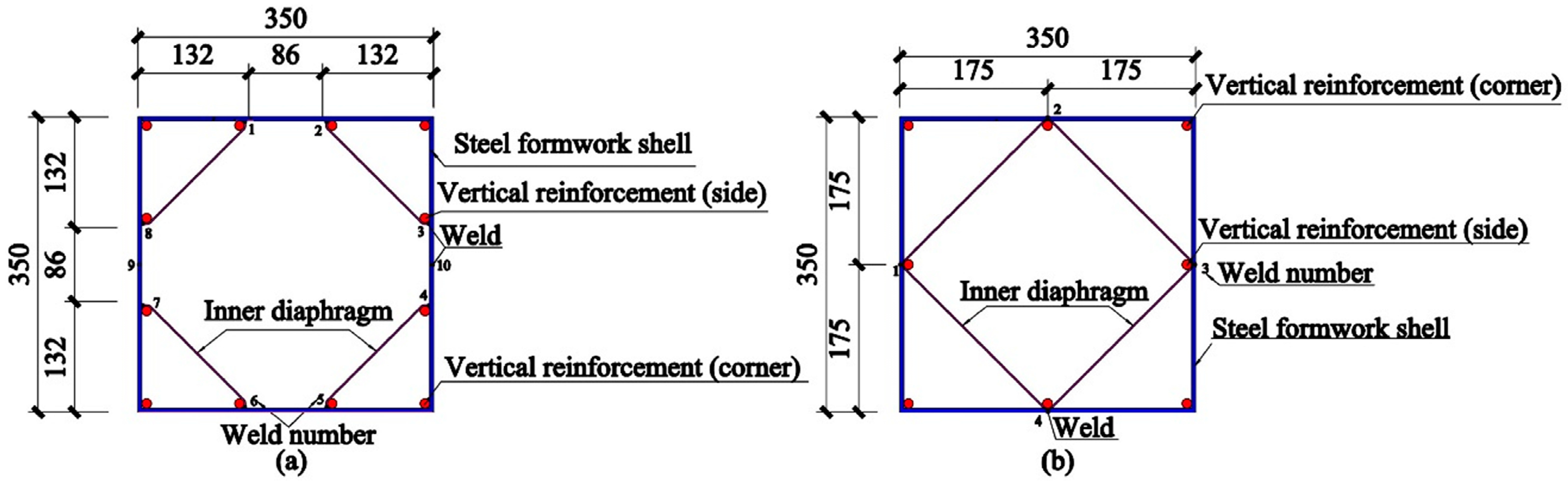
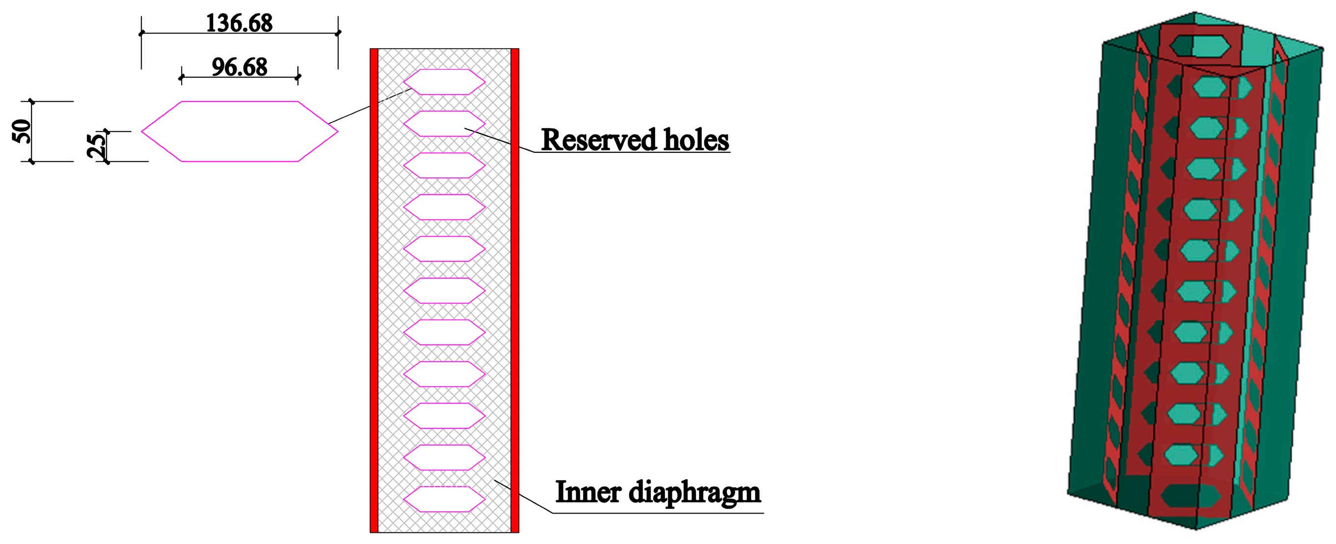
2.1. Design of Components

In this study, six steel formwork concrete columns (CFSF1–CFSF6) were designed and fabricated according to a scale of 1:3 by adopting steel formwork thickness, rebar diameter, and internal diaphragm style as the design parameters. Among them, CFSF1–CFSF4 used four internal diaphragms not in contact with one another, while CFSF5–CFSF6 used internal diaphragms in contact with each other, as shown in Figure 1 and Figure 2, respectively. Adding tie bars to the steel formwork concrete column can better restrain the core concrete and give full play to the performance of concrete and steel. The brace is used as the tie member, which makes it easy to cause uneven stress of the brace due to the blanking error, which causes the local brace to be damaged first, and the column member is damaged before all the braces have fully developed their tensile strength. The uniform stress of the plate can be better achieved by using the inner diaphragm as the tie piece. Therefore, inner diaphragms are selected as the internal ties of column members. The column height is 1050 mm, and the section length and width are 350 mm each; all test pieces are made of C30 concrete; and Q345 steel is used for steel formwork shell and inner diaphragm. The steel formwork design is very thin because when the column is under pressure, the core concrete has a tendency to bulge out, which is the external steel plate force state for plane bending. Using the form of ‘Thin formwork + bar’, the steel bar is equivalent to the rib beam of the thin formwork. As such, on the premise of the same amount of steel, the form of ‘Thin plate + rib’, the mechanical performance is better. The steel bar is arranged at the junction of the inner partition plate and the thin die shell so that the bar has two-way pull-ties and does not easily bend under pressure. (See the design parameters of components in Table 1 and the mechanical properties of materials in Table 2.)
To sum up, when the amount of steel used for the steel formwork, the inner diaphragm, and the bar is in an optimal proportion, all the components of the column, that is, the concrete, steel formwork, bar, and internal diaphragm, can display its ultimate strength so that the column can obtain maximum bearing capacity.
The section shown in Figure 1a required ten full welds, while that shown in Figure 1b required only four after spot welding fixation. The sequence of construction is as follows:
(1)
Spot weld the bar at the corresponding position of the inner diaphragm;
(2)
Place the inner diaphragm with spot welded bar against the corresponding position of the steel formwork;
(3)
Welding the inner diaphragm to the steel formwork and the part of the steel formwork where the bar contacts the steel formwork.
CFSF5 and CFSF6 were designed with different section forms to investigate whether a thinner steel formwork can realize the design idea. Additionally, this section form reduced the number of welds, lowering the cost. For inner diaphragms, in order to achieve the above design goal, in theory, the inner diaphragm should be connected to the steel formwork by full welding. However, when connecting the spaces in the column separated by the inner diaphragm, holes are arranged along the fixed spacing of the inner diaphragm, the purpose of the opening is to connect the concrete in different partition intervals during concrete pouring construction and to reduce concrete defects. It conveniently embeds internal diaphragms in concrete and reduces the slip between them, thus effectively forming an integral whole.

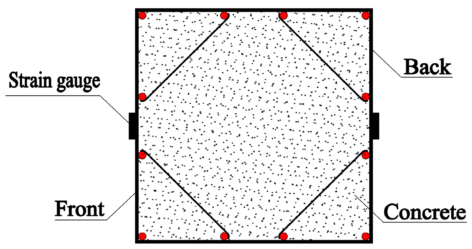
2.2. Arrangement of Measuring Points
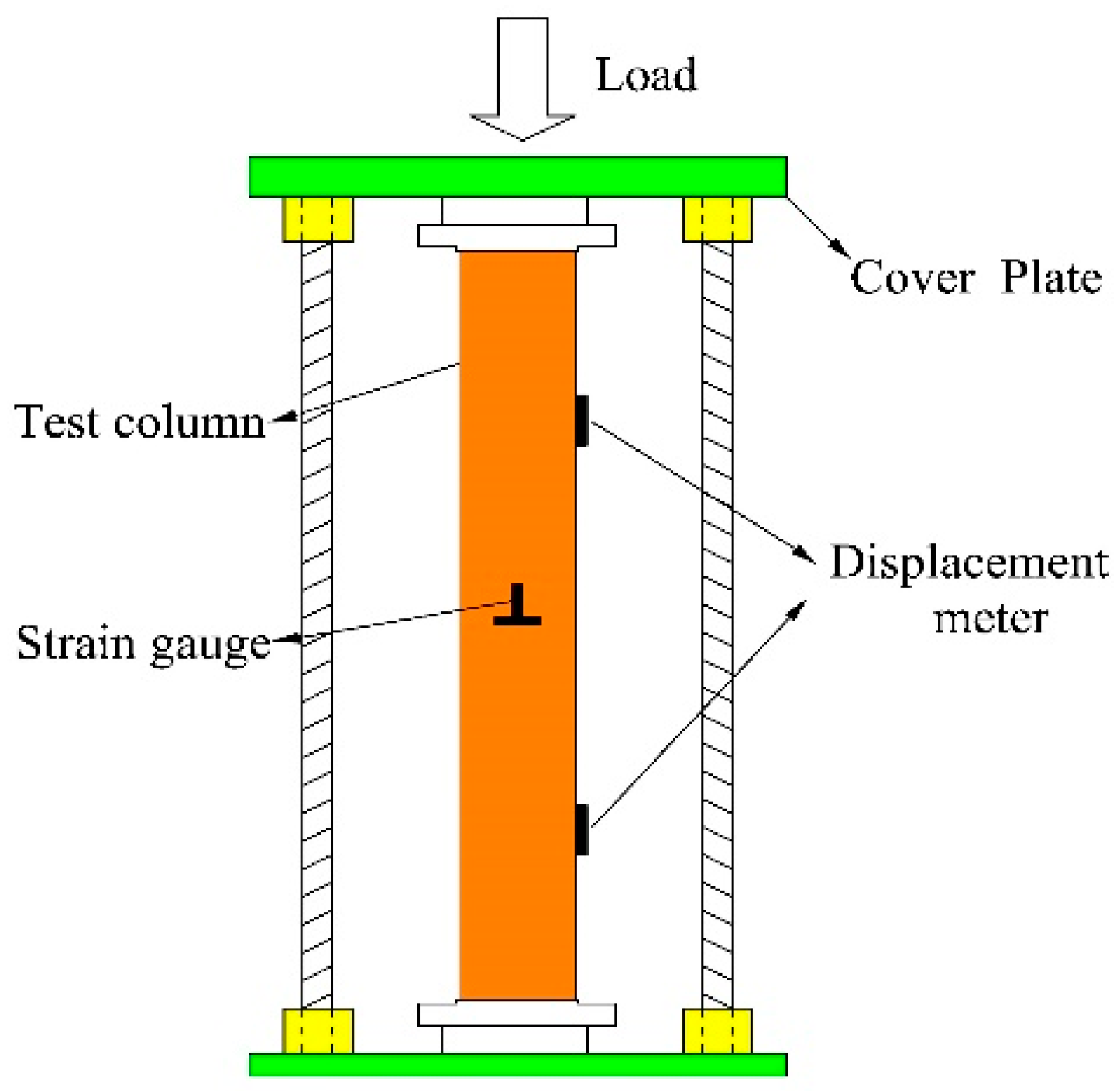
In order to measure the axial compression deformation of a specimen in the test process, two longitudinal and transverse strain gauges were uniformly arranged at the two interfacial positions of the steel formwork, thus measuring the strain development of the specimen during axial compression, as shown in Figure 3.

2.3. Loading Scheme

Monotonic static loading was applied on specimens using the device shown in Figure 4. Geometric and physical alignment were performed before formal loading by preloading to 15% of the estimated bearing capacity (i.e., 600 kN). Each specimen was aligned through correction, followed by unloading. Formal loading started after a 3 min interval. Constant-displacement continuous loading was adopted and proceeded at the 1 mm/min rate. When the vertical displacement of a specimen reached 40 mm, it was regarded as having failed, in which case, loading was stopped.

3. Failure Characteristics and Result Analysis

As shown in Figure 5, specimen 1 experienced no angular tear, and top buckling was obvious on one side but non-obvious on the other. Large wrinkles appeared on one side of the steel formwork tube (in the middle, opposite to the top buckling position). Specimen 2 showed no angular tear or evident top buckling, and prominent wrinkles occurred on the steel formwork tube. Specimen 3 underwent severe damage with a four-way angular tear and obvious top buckling. In the case of specimen 4, there were obvious four-way angular tears and top buckling, and the wrinkles on the steel formwork tube were evenly distributed (on the upper side).
Specimen 5 showed serious damage with a three-way angular tear and obvious top buckling. The wrinkles on the steel formwork tube were non-obvious, and there was only slight deformation in the lower part of the steel formwork tube. Specimen 6 indicated serious damage with a three-way angular tear and obvious top buckling. There were wrinkles at a moderate height on the steel formwork tube (concentrated in the upper part).
By observing the failure modes of these specimens, it was found that obvious top buckling occurred in most cases, suggesting that the top is the weak link. The possible reason for this is that, due to the end plate at the top, the concrete pouring in the top corners (especially the angles) may not be compact enough, which causes the top concrete to undergo compression failure first. Top buckling can be solved by improving the quality of the top concrete, ensuring compact concrete pouring in the corners (or providing proper reinforcement at the top) and increasing the number of spot weldings for angular rebars.
Referring to a combination of Figure 5 and Table 3, we can draw the following conclusions:
The sectional configuration shown in Figure 1a was adopted for CFSF-1–CFSF-4. In comparison to CFSF-1 and CFSF-2, CFSF-3 and CFSF-4 had a higher ultimate bearing capacity (i.e., 4.55–8.14% higher), suggesting that it is enough for internal diaphragm thickness to meet the tying requirements of steel formworks. Under the premise of the same amount of steel used, steel should be arranged towards the peripheral steel formwork or vertical reinforcement as far as possible.
The sectional configuration shown in Figure 1b was adopted for CFSF-5 and CFSF-6. These two specimens’ average ultimate bearing capacity was close to that of CFSF-1 and CFSF-2, suggesting that the sectional configuration in Figure 1b is also advisable. However, there was a 7.22% difference in the ultimate bearing capacity between these two specimens and great fluctuations in the ultimate bearing capacity. Combined with the fabrication methods and failure modes of these specimens, CFSF-5 designed a larger diameter of steel bars and a thinner inner diaphragm, while CFSF-6 did not, indicating that the inner diaphragm has a more significant impact on the ultimate bearing capacity of the specimen. Therefore, when the sectional configuration in Figure 1b is adopted for cost reduction, the thickness of the inner clapboard of the specimen should be increased.
CFSF-3 and CFSF-4 were compared in consideration of fabrication errors. The comparison results show that the difference in ultimate bearing capacity between the two was small, which may imply that it is easier to guarantee the fabrication quality of specimens with the sectional configuration in Figure 1a.

4. Finite Element Model and Result Discussion

A numerical model was built for steel formwork concrete columns under axial pressure using large finite element software ABAQUS (Version 2021) to determine the true stress state of steel formwork concrete columns in engineering practice. The deformation shape, direction, buckling, and stress value were observed under the same displacement. The results were compared with test data to validate the reliability of the finite element model, offering references for engineering design.

4.1. Finite Element Model

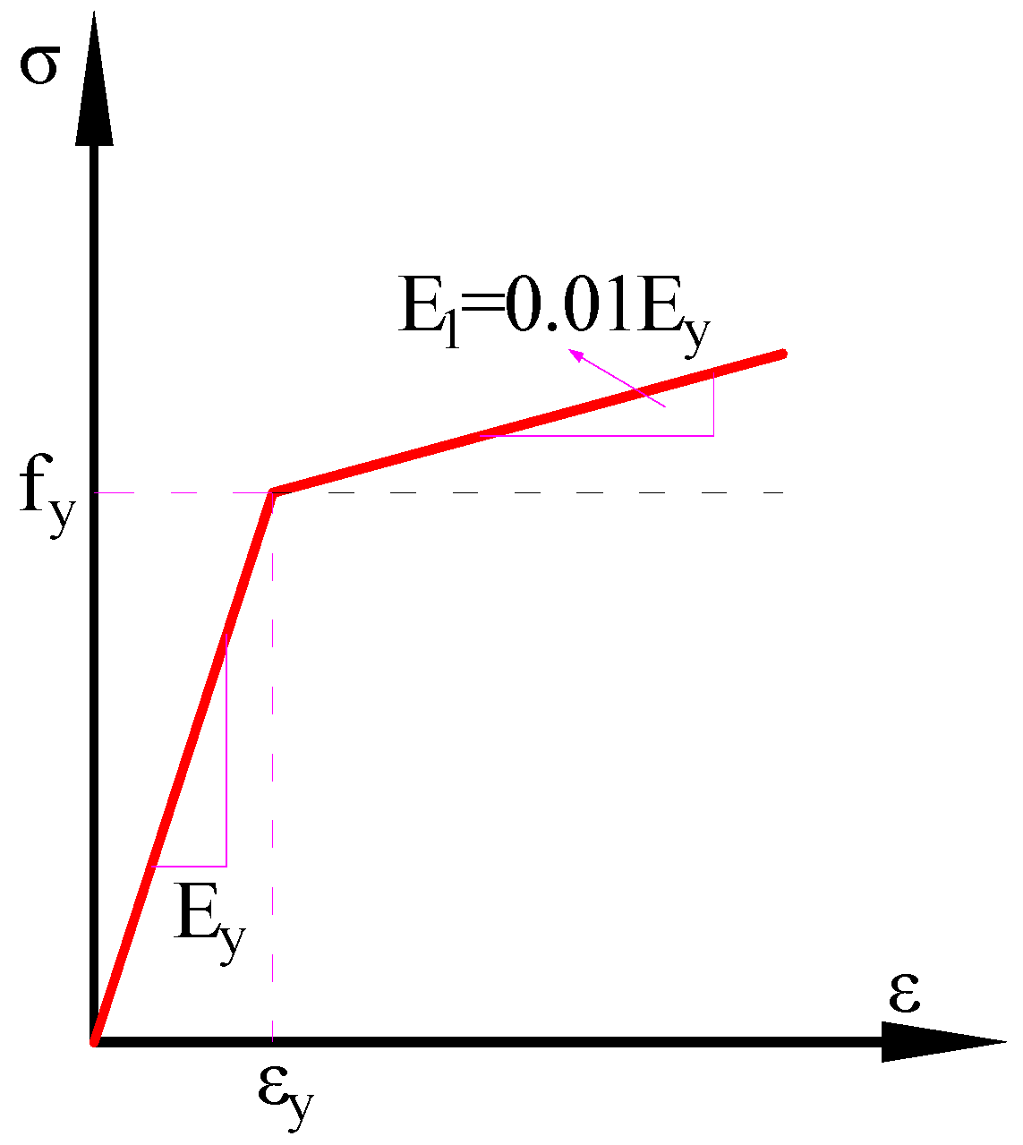
4.1.1. Constitutive Relationship of Materials

This study adopted the concrete damaged plasticity (CDP) model, which applies to brittle materials, such as concrete. Based on concrete isotropy, concrete’s tensile cracking and compressive fracture were simulated [29]. The damage, in this case, was a progressive weakening in the internal cohesion of the material under loading, which produced defects, cracks, and micropores in the loaded material [30]. The stress-strain relationships under tension and compression were described using the formula displayed in Appendix C of the Code for Design of Concrete Structures [31]. The elastic modulus of concrete was determined according to this code, and its Poisson’s ratio adopted 0.1, as shown in Table 4.
This study adopted the double broken line model for rebars, with a hardening coefficient of 0.01, as shown in Figure 6. The stress-strain curve after yield was simplified into an oblique straight line according to the Mises yield criterion. (See the material parameters of rebars in Table 5.)

4.1.2. Model Settings

The components in the numerical simulation were set as follows in combination with the test components: concrete was modeled using C3D8R elements; longitudinal rebars were modeled using T3D2 Truss elements; and steel formworks and internal diaphragms were modeled using S4R shell elements. A tie connection was set between the concrete and steel formworks/inner diaphragms at the edge and in the core area; the tie connection mode makes the two faces connected together no longer separate and makes them deform together, which can reflect the ability of the two to work together. The embedding connection was used between the concrete and rebars. The column top was defined using a set of nodes, while the column bottom was fully fixed to confine six directional degrees of freedom (DOFs). Moreover, the displacements in the x and y directions and the rotational DOF in the z direction of the rebars were confined. The steel formwork, the concrete, the end plate, and the bar were divided into grids, and the steel formwork and the inner diaphragm board were made into a whole by merging, so as to arrange the bars. The inner diaphragm can be divided into several quadrangles by an extension surface, which can be divided into structured meshes. The advantages of this method include fast mesh generation, high quality, and increased proximity to the actual model. Loading was applied using displacement loading, as shown in Figure 7.

4.1.3. Comparison between Numerical Simulation and Test Results

Deformation Nephograms

Figure 8 shows the simulation nephograms corresponding to the test results. (See the CFSF-1 cavity column in Figure 8a and CFSF-6 in Figure 8b). It can be seen that the maximum strain position of the finite element model is the same as that in the tests, that is, located in the middle of the column. This suggests that the finite element model can well reflect the buckling deformation of specimens. The edge concrete at the upper end of the column broke during the test process. This phenomenon can be compared to the compressive damage DAMAGEC of the finite element model, which reflects the damage (often within the range of 0–1) to concrete under compression. Generally, a value above 0.9 means the concrete has completely broken [32]. As seen from Figure 8a, the concrete damage in the finite element model exceeded 0.9, indicating that the failure mode of concrete in the numerical simulation is consistent with the test results. The position with the largest displacement, observed from the displacement nephogram, is located at the column top. The test diagram shows that deformation and damage are concentrated in the upper and middle parts of the column, while the lower and middle parts are free from deformation and damage, indicating good agreement between the simulation and test results. However, the upper steel formwork of CFSF-1 is not as seriously damaged as CFSF-6. This is because the steel formwork of CFSF-1 was designed with a larger wall thickness and consequently possessed a stronger ability to confine and deform.

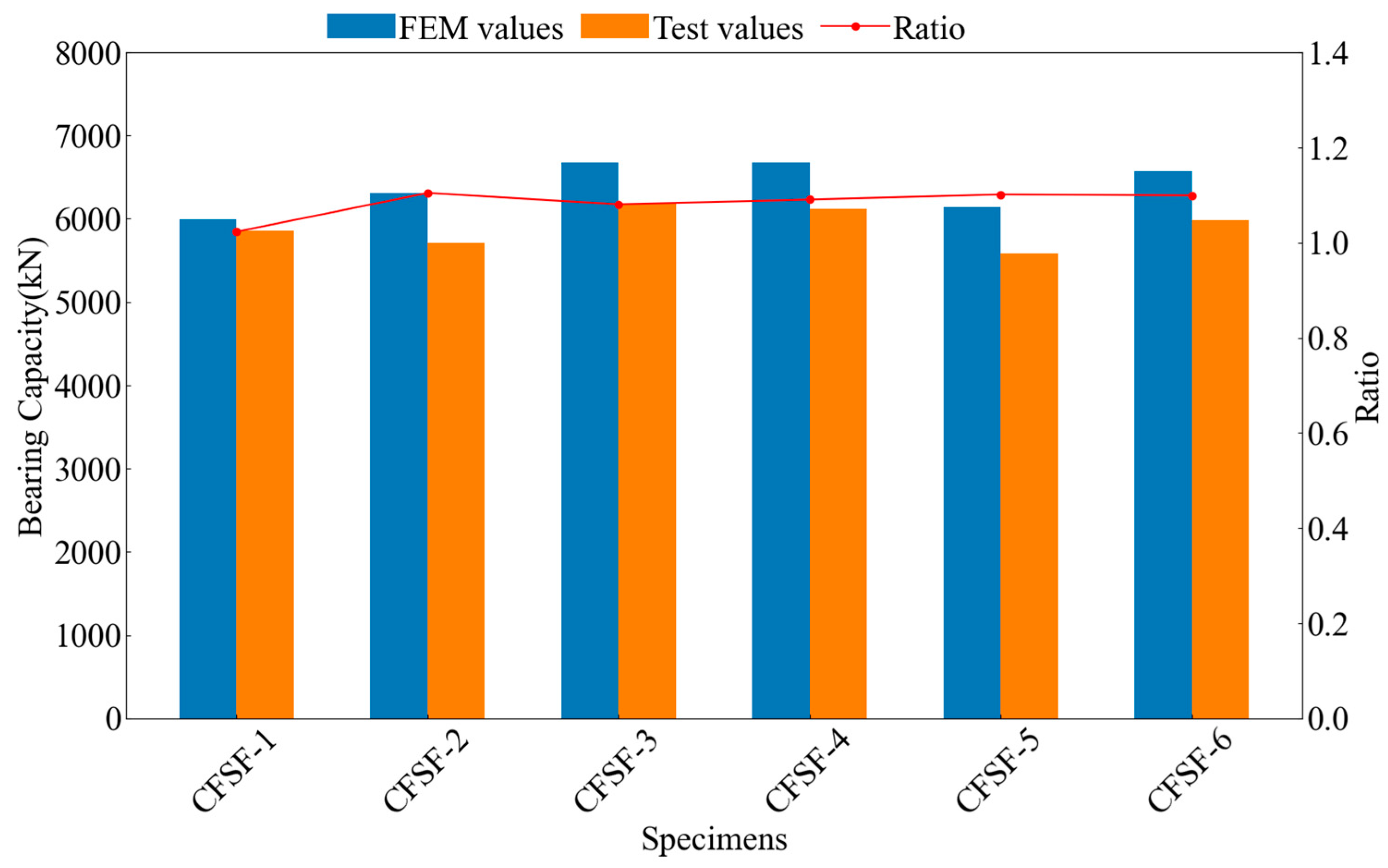
Comparison Diagram of Bearing Capacity

The ultimate bearing capacity results of specimens were obtained from the tests and the numerical simulation, and histograms were drawn for comparison, as shown in Figure 9. It can be seen that the ratio between the simulation and test results is around 1. Error calculation yielded a gap of 2–10%, pointing to material defects and human factors. The bearing capacity of CFSF-1 is about 2.4% higher than that of CFSF-2. CFSF-1 used rebars with an angular diameter of 16 mm and internal diaphragms with a thickness of 1.8 mm. At the same time, CFSF-2 adopted rebars with an angular diameter of 20 mm and internal diaphragms with a thickness of 1.2 mm, which indicated that the influence of corner bar diameter on bearing capacity is lower than the thickness of inner diaphragm. When comparing CFSF-5 and CFSF-6 in a similar scenario, the ultimate bearing capacity of CFSF-6 was 6.7% higher than that of CFSF-5. Clearly, it can be seen that the thickness of the inner diaphragm has a more obvious effect on the bearing capacity of both forms. Taken together, the figure suggests that the constitutive relationship of the material is close to reality and that the numerical simulation results are desirable.

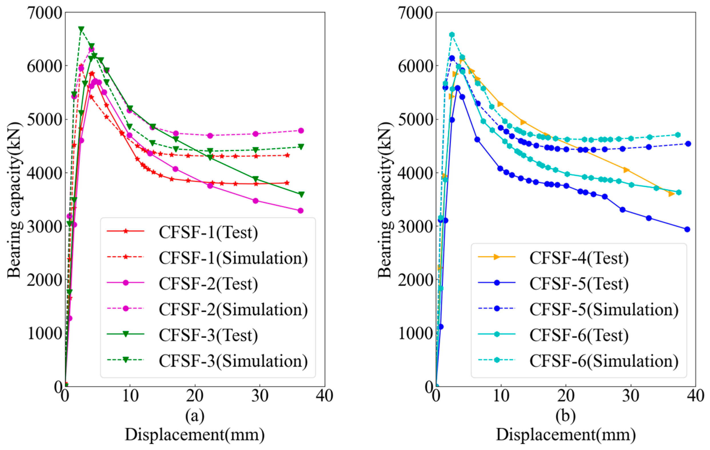
4.2. Load-Axial Displacement Curves

Figure 10 shows all specimens’ measured and simulated load-axial displacement curves. It can be seen that the simulation results were slightly greater than the test results. When the load reached its limit value, the bearing capacity of each specimen began to decline. However, the bearing capacity curve of the simulation results presented a second upward trend after reaching the ultimate load, while that of the test results gradually declined after reaching the ultimate load without showing any further increase.
As seen in Figure 10a, the ultimate bearing capacity of CFSF-3 was higher than that of CFSF-1 and CFSF-2, whether in the test results or the simulation results. The simulation results further validated the conclusion of the test analysis, that is, under the premise that the same amount of steel was used and that the steel formwork was well tired by internal diaphragms, steel should be arranged towards the peripheral area as far as possible to improve the ultimate bearing capacity of the specimens.
As seen in Figure 10b, the bearing capacity of CFSF-6 is higher than that of CFSF-5, and the simulation and test results are consistent. However, the difference in the ultimate bearing capacity between CFSF-6 and CFSF-5 was smaller in simulation results, which reflects the effect of fabrication errors on test results.

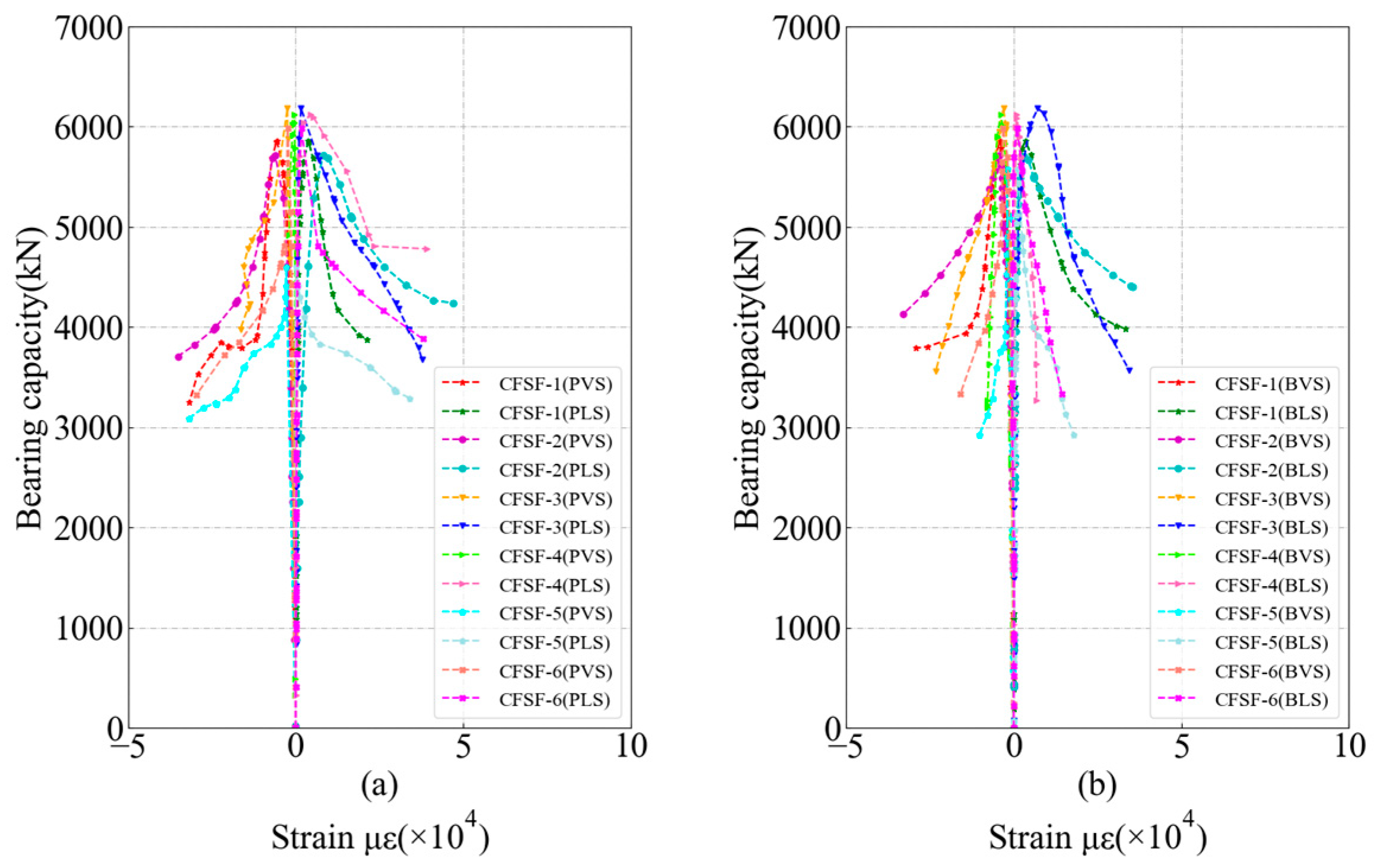
4.3. Load-Strain Curves

The strain values of the specimens were obtained using the longitudinal and transverse strain gauges on the front and back of the steel formwork and then combined with the loading results to draw the load–strain curves, as shown in Figure 11 (where “PVS” denotes the front longitudinal strain, “PLS” denotes the front transverse strain, “BVS” denotes the back longitudinal strain, and “BLS” denotes the back transverse strain). In the initial loading stage, all strains increased linearly. With the increase in load, the strain of the external steel formwork gradually reached the yield strain. Almost all measured strains were more significant than the yield strain limit until the load increased to the limit and the slope of the curve decreased. The above results indicate that core concrete has an effective supporting effect on steel formworks and improves the bearing capacity of specimens. The differences between transverse and longitudinal strains on the front and back of the steel formwork were small. Overall, a comparison between the two types of design forms revealed that the deformability and ductility of Figure 1a were better after reaching the ultimate bearing capacity. A possible reason for this is that concrete expands due to axial compression when the load exceeds the ultimate load. In the design form of Figure 1a, core concrete is in contact with the steel formwork, which enhances the interaction between the two materials.

5. Conclusions

The steel formwork concrete column fine structure performance. In the future, its construction and the bridge will have widespread application space. Therefore, it is an important research topic to explore the performance of steel formwork concrete column.
The change laws in the bearing capacity of different forms of steel formwork concrete columns were explored in this study. Moreover, tests and numerical simulations analyzed the factors influencing the bearing capacity of six steel formwork concrete columns under axial compression. The results revealed the laws governing the effects of failure mode and rebar arrangement on the ultimate bearing capacity of prefabricated steel formwork concrete columns. The main conclusions are as follows:
(1)
A specimen’s failure process begins with the steel formwork’s local buckling. After that, the concrete expands under compression, resulting in the tear of the steel formwork. Finally, the top concrete is crushed, causing the loss of bearing capacity.
(2)
Buckling is evident at the top of a steel formwork column, constituting a weak link in the whole column. A possible reason for this is that, due to an end plate at the top, the concrete pouring in the top corners may not be compact enough, which causes the top concrete’s compression failure, followed by steel formwork tearing.
(3)
Compared with the bar, the inner diaphragm has a higher effect on the bearing capacity of the column, so the thickness and layout of the inner diaphragm can be further studied.
(4)
Under the premise that the same amount of steel was used and that the steel formwork was well tired by internal diaphragms, steel should be arranged towards the peripheral area as far as possible to improve the ultimate bearing capacity of specimens.
(5)
The design form that increases the contact area between the steel formwork and concrete allows the column to show better ductility after reaching the ultimate bearing capacity. Further experimental research can be carried out to explore the seismic performance of this system.

Author Contributions

Conceptualization, Z.Y. and H.G.; Methodology, S.L., Y.L. and H.G.; Writing—original draft, J.W.; Writing—review & editing, S.L., Z.Y. and Y.L.; Supervision, Z.Y., Y.L. and H.G.; Funding acquisition, S.L. All authors have read and agreed to the published version of the manuscript.

Funding

This research received no external funding.

Data Availability Statement

Not applicable.

Conflicts of Interest

The authors declare no conflict of interest.

References

  1. Jaillon, L.; Poon, C.S.; Chiang, Y.H. Quantifying the waste reduction potential of using prefabrication in building construction in hong kong. Waste Manag. 2009, 29, 309–320. [Google Scholar] [CrossRef]
  2. Huang, W.; Hu, G.-X. Research on seismic behavior of recoverable prefabricated RC beam-column joints. Eng. Mech. 2022, 39, 165–176, 189. (In Chinese) [Google Scholar] [CrossRef]
  3. Jaillon, L.; Poon, C.S. Life cycle design and prefabrication in buildings: A review and case studies in hong kong. Autom. Constr. 2014, 39, 195–202. [Google Scholar] [CrossRef]
  4. Zheng, L.-Q.; Chen, X.-Y.; Wei, C.-G.; Yan, G.-Y. Seismic performance of prefabricated beam-to-column joint with replaceable energy-dissipating steel hinge. Bull. Earthq. Eng. 2022, 20, 1865–1895. [Google Scholar] [CrossRef]
  5. Spacone, E.; El-Tawil, S. Nonlinear analysis of steel-concrete composite structures: State of the art. J. Struct. Eng. 2004, 130, 159–168. [Google Scholar] [CrossRef]
  6. Nie, J.; Wang, J.; Gou, S.; Zhu, Y.; Fan, J. Technological development and engineering applications of novel steel-concrete composite structures. Front. Struct. Civ. Eng. 2019, 13, 1–14. [Google Scholar] [CrossRef]
  7. Pellegrino, C.; Maiorana, E.; Modena, C. FRP strengthening of steel and steel-concrete composite structures: An analytical approach. Mater. Struct. 2009, 42, 353–363. [Google Scholar] [CrossRef]
  8. Wang, Y.C. Performance of steel–concrete composite structures in fire. Prog. Struct. Eng. Mater. 2005, 7, 86–102. [Google Scholar] [CrossRef]
  9. Wang, D.; Tan, B.; Xiang, S.; Wang, X. Fatigue crack propagation and life analysis of stud connectors in steel-concrete composite structures: 12. Sustainability 2022, 14, 7253. [Google Scholar] [CrossRef]
  10. Badalassi, M.; Braconi, A.; Cajot, L.-G.; Caprili, S.; Degée, H.; Gündel, M.; Hjiaj, M.; Hoffmeister, B.; Karamanos, S.A.; Salvatore, W.; et al. Influence of variability of material mechanical properties on seismic performance of steel and steel–concrete composite structures. Bull. Earthq. Eng. 2017, 15, 1559–1607. [Google Scholar] [CrossRef] [Green Version]
  11. Chen, C.; Wang, C.; Sun, H. Experimental study on seismic behavior of full encased steel-concrete composite columns. J. Struct. Eng. 2014, 140, 04014024. [Google Scholar] [CrossRef]
  12. Hajjar, J.F. Composite steel and concrete structural systems for seismic engineering. J. Constr. Steel Res. 2002, 58, 703–723. [Google Scholar] [CrossRef]
  13. Huang, F.; Yu, X.; Chen, B. The structural performance of axially loaded cfst columns under various loading conditions. Steel Compos. Struct. 2012, 13, 451–471. [Google Scholar] [CrossRef]
  14. Zeghiche, J.; Chaoui, K. An experimental behaviour of concrete-filled steel tubular columns. J. Constr. Steel Res. 2005, 61, 53–66. [Google Scholar] [CrossRef]
  15. Wang, J.H.; He, J.; Xiao, Y. Fire behavior and performance of concrete-filled steel tubular columns: Review and discussion. J. Constr. Steel Res. 2019, 157, 19–31. [Google Scholar] [CrossRef]
  16. Yang, Y.-F.; Han, L.-H. Experimental behaviour of recycled aggregate concrete filled steel tubular columns. J. Constr. Steel Res. 2006, 62, 1310–1324. [Google Scholar] [CrossRef]
  17. Gupta, P.K.; Sarda, S.M.; Kumar, M.S. Experimental and computational study of concrete filled steel tubular columns under axial loads. J. Constr. Steel Res. 2007, 63, 182–193. [Google Scholar] [CrossRef]
  18. Thai, S.; Thai, H.-T.; Uy, B.; Ngo, T. Concrete-filled steel tubular columns: Test database, design and calibration. J. Constr. Steel Res. 2019, 157, 161–181. [Google Scholar] [CrossRef]
  19. Beutel, J.; Thambiratnam, D.; Perera, N. Cyclic behaviour of concrete filled steel tubular column to steel beam connections. Eng. Struct. 2002, 24, 29–38. [Google Scholar] [CrossRef]
  20. Ou, Z.; Chen, B.; Hsieh, K.H.; Halling, M.W.; Barr, P.J. Experimental and analytical investigation of concrete filled steel tubular columns. J. Struct. Eng. 2011, 137, 635–645. [Google Scholar] [CrossRef]
  21. Evirgen, B.; Tuncan, A.; Taskin, K. Structural behavior of concrete filled steel tubular sections (cft/cfst) under axial compression. Thin-Walled Struct. 2014, 80, 46–56. [Google Scholar] [CrossRef]
  22. Giakoumelis, G.; Lam, D. Axial capacity of circular concrete-filled tube columns. J. Constr. Steel Res. 2004, 60, 1049–1068. [Google Scholar] [CrossRef]
  23. Mao, X.Y.; Xiao, Y. Seismic behavior of confined square cft columns. Eng. Struct. 2006, 28, 1378–1386. [Google Scholar] [CrossRef]
  24. Ding, F.-X.; Lu, D.-R.; Bai, Y.; Zhou, Q.-S.; Ni, M.; Yu, Z.-W.; Jiang, G.-S. Comparative study of square stirrup-confined concrete-filled steel tubular stub columns under axial loading. Thin-Walled Struct. 2016, 98, 443–453. [Google Scholar] [CrossRef]
  25. Ding, F.-X.; Fu, L.; Liu, X.-M.; Liu, J. Mechanical performances of track-shaped rebar stiffened concrete-filled steel tubular (scfrt) stub columns under axial compression. Thin-Walled Struct. 2016, 99, 168–181. [Google Scholar] [CrossRef]
  26. Ge, H.; Usami, T. Strength of concrete-filled thin-walled steel box columns: Experiment. J. Struct. Eng. 1992, 118, 3036–3054. [Google Scholar] [CrossRef]
  27. Dong, H.; Li, Y.; Cao, W.; Qiao, Q.; Li, R. Uniaxial compression performance of rectangular cfst columns with different internal construction characteristics. Eng. Struct. 2018, 176, 763–775. [Google Scholar] [CrossRef]
  28. Cha, S.-L.; Lee, J.-S.; Park, C.-K.; Kim, J.-K.; Kwon, S.-H. Experimental investigation on behavior of rectangular concrete-filled tubular columns considering diaphragms. Materials 2020, 13, 4412. [Google Scholar] [CrossRef]
  29. Demin, W.; Fukang, H. Investigation for plastic damage constitutive models of the concrete material. Procedia Eng. 2017, 210, 71–78. [Google Scholar] [CrossRef]
  30. Zeng, Y.; Hu, L.-M. ABAQUS plastic damage constitutive model for concrete parameter calculation and checking. Sci. Hydropower Energy 2019, 37, 106–109. (In Chinese) [Google Scholar]
  31. GB50010-2010; Code for Design of Concrete Structures. China Architecture & Building Press: Beijing, China, 2010. (In Chinese)
  32. Chen, Z.; Dong, S.; Du, Y. Experimental study and numerical analysis on seismic performance of frp confined high-strength rectangular concrete-filled steel tube columns. Thin-Walled Struct. 2021, 162, 107560. [Google Scholar] [CrossRef]
Figure 1. Section style and dimensions. (a) Description of the partition adopts hexagon cross section in the form of arrangement is contained in the first panel; (b) Description of the partition using quadrilateral cross section in the form of arrangement is contained in the second panel.
Buildings 13 00820 g001
Figure 2. Style of inner diaphragm.
Buildings 13 00820 g002
Figure 3. Strain gauge setup.
Buildings 13 00820 g003
Figure 4. Test setup for compressive strength of CFSF columns.
Buildings 13 00820 g004
Figure 5. Failure mode of test piece.
Buildings 13 00820 g005
Figure 6. Constitutive model of reinforcement.
Buildings 13 00820 g006
Figure 7. Finite element model.
Buildings 13 00820 g007
Figure 8. Comparison of deformation nephograms.
Buildings 13 00820 g008
Figure 9. Bearing capacity comparison.
Buildings 13 00820 g009
Figure 10. Load-axial displacement curve. (a) Description of the CFSF1–3 tests and simulations is contained in the first panel; (b) Description of the CFSF4–6 tests and simulations is contained in the second panel.
Buildings 13 00820 g010
Figure 11. Load-strain curves. (a) Description of the vertical and horizontal strains on the front of the specimen is contained in the first panel; (b) Description of the vertical and lateral strains on the back of the specimen is contained in the second panel.
Buildings 13 00820 g011
Table 1. Design parameters of specimens.
Specimen NumberThe Thickness of the Steel Shell (mm)Vertical Rebar (Corner Reinforcement + Side Reinforcement)Inner Diaphragm (mm)
CFSF-11.84 Φ 16 + 8 Φ 121.8
CFSF-21.84 Φ 20 + 8 Φ 121.2
CFSF-32.04 Φ 18 + 8 Φ 121.2
CFSF-42.04 Φ 18 + 8 Φ 121.2
CFSF-51.54 Φ 20 + 4 Φ 181.2
CFSF-61.54 Φ 18 + 4 Φ 161.5
Note: CFSF3 and CFSF4 have the same parameters in order to investigate the effects of manufacturing errors.
Table 2. Mechanical property.
ConcreteVertical Rebar
GradeC30GradeHRB400
Young’s modulus, E c (MPa)30,000.00Young’s modulus, E s (MPa)200,000.00
Design value of axial compressive strength, f c (MPa)14.3Steel yield strength, f y k (MPa)400
Steel ultimate tensile strength, f s t k (MPa)540
Table 3. Ultimate bearing capacity test value.
Specimen NumberCFSF-1CFSF-2CFSF-3CFSF-4CFSF-5CFSF-6
Ultimate bearing capacity (kN)5858.295716.376181.856125.095580.135983.17
Table 4. Parameters of concrete.
Poisson’s RatioDilation AngleEccentricity f b 0 / f c 0 kViscosity Parameter
0.16300.11.160.6670.005
Table 5. Reinforcement material parameters.
Yield Strength (MPa)Yield StrainUltimate Strength (MPa)Ultimate Strain
4000.0024550.072
Disclaimer/Publisher’s Note: The statements, opinions and data contained in all publications are solely those of the individual author(s) and contributor(s) and not of MDPI and/or the editor(s). MDPI and/or the editor(s) disclaim responsibility for any injury to people or property resulting from any ideas, methods, instructions or products referred to in the content.

