Article

Heat Flow through a Facede with a Controlled Ventilated Gap

1
Institute of Building Services, Faculty of Civil Engineering, Brno University of Technology, 60200 Brno, Czech Republic
2
Institute of Building Structures, Faculty of Civil Engineering, Brno University of Technology, 60200 Brno, Czech Republic
*
Author to whom correspondence should be addressed.
Buildings 2023, 13(3), 817; https://doi.org/10.3390/buildings13030817
Submission received: 1 March 2023 / Revised: 15 March 2023 / Accepted: 17 March 2023 / Published: 20 March 2023
(This article belongs to the Special Issue Rehabilitation and Reconstruction of Buildings)

Abstract

:
The article presents current research results in the field of airflow through a façade with a width of 1 m and a height of 13.7 m and with a ventilated gap, and its effect on the year-round heat balance of this façade. An idea to influence airflow in the ventilated gap of the façade is presented based on the results of developed software and the suitability of closing the air gap in winter and in the transition period of the year is described. First, the boundary conditions of the calculations, which are further used in the energy balance between the interior of the building and the exterior environment are defined. In order to include these influences, a discrete analytical calculation was created. It consists of the time distribution of the investigated thermal phenomena calculations. A significant finding is an obvious benefit of controlling the airflow through a ventilated gap in the winter and especially in the transitional period of the year. This technological knowledge has a high potential for energy savings related to the heating of buildings. As the calculations show, airflow control through a ventilated façade reduces heat flow by 25–30% on average, and in contrast, it increases heat gains by 20% and the specific values are presented within the article.

1. Introduction

Ventilated façades (double-skin façades, DSF) are more and more common methods to install the external cladding of buildings. The right design and structural solution of the façade air gap may help to minimize heat losses in winter and in contrast, reduce heat gains in summer. It all depends on the façade orientation and its structural design.
The airflow through the façade ventilated air layer is mainly natural, forced ventilation is used for double-skin façades. Natural flow is triggered by air convection due to façade sun exposure or waste heat flowing through the building envelope from the interior. Warm air then flows upwards to the ventilation holes near the attic or under the window sills of the higher-installed windows, while the air flows from the exterior through the inlet holes above the ground or in lintels. In addition, air exchange occurs in façades with open joints in between individual exposed cladding boards [1].
The air flowing through a ventilated air gap helps to reduce overheating of a structure in summer that is caused by the façade sun exposure, since the external façade surface is cooled by the air flowing through the air gap, thus reducing the heat flow affecting the building interior. In winter, the airflow is triggered by the loss of heat flow coming from the interior. At night under a cloudless sky, the cooling of the façade external face area occurs, based on the surface thermal radiation against the cold clear sky, which may have a positive effect on ventilated façades in comparison to other façades [1].
In addition, in winter the effect of wind leads to the cooling of the external building face since it reduces its surface temperature. In case the contact cladding system is used, a bigger cooling effect occurs on the external façade surface than on the ventilated façade where the offset cladding creates a “dampening area”, and the velocity of airflow is often lower than the velocity of wind in front of the façade. In contrast, the drawback of ventilated façades is the lower effectiveness of the thermal insulation layer due to airflow, since the flowing air velocity increases in the joint due to the effect of wind [2].
Furthermore, the use of a windproof and diffuse open layer is necessary for the wind to move to the surface layer of the fiber thermal insulation, or to protect it against rainwater, which may enter the joint from driven rain or snow through leaks in the cladding [2].
Moreover, a bearing structure of the external façade cladding, which may be made from steel, aluminum, or wood, is used for the airflow in the joint of the ventilated façade. However, this structure may not affect the airflow in the vertical direction. Some construction parts may be installed in a thermal insulation layer, which may be locally reduced to up to 10 to 5 mm of the joint thickness due to bearing console construction elements. Such narrowing needs to be assessed in the designing stage in order to ensure sufficient airflow in the ventilated joint [3].
As reported in the literature [4], the idea of DSF has been a source of numerous studies since the 1990s which shows, among other findings, that shading devices can reduce external heat gain if installed correctly in the DSF cavity. Further theoretical and experimental research works are necessary to clearly understand the challenges, effects, and implications of DSF.
Façades with a ventilated air layer are also discussed in specialist literature. The majority of available studies, e.g., [5,6,7,8,9,10] are focused on glazed double-skin façades. All the mentioned studies deal with the elimination of solar radiation by blinds. The article [5] analyzes the impact of slat tilt angle, blind position, and air outlet position on airflow development, [6] performs a detailed analysis of the temperature field for a glazed façade with blinds and presents heat gain due to direct solar radiation and convection through the façades to the internal spaces. An analysis of the temperature field with blinds and glazed façade can also be found in [9]. The use of mechanical/forced façade ventilation is also mentioned in technological literature, e.g., in a study [11], where a procedure for modeling glazed double façades, comprising a spectral optical and a computational fluid dynamic model, is described, and simulated results are compared with the data derived from an experimental investigation of mechanically ventilated 2 m high glazed double façades. The conclusions of this study imply that simple models assuming piston flows can lead to inaccurate results.
Investigating a façade with a non-transparent cladding, of relatively great height (min. 3 m), has not been described in specialist literature so far. The majority of studies describe smaller-size façades or glazed façades of smaller height, mostly up to 2 m, and also with a variable gap width. For example, Zöllner in [8] describes experiments performed on glazed double-skin façades for gaps of 0.3, 0.6 and 0.9 m width. The time and local averaged overall heat transfer coefficients for solar radiation that augmented turbulent mixed convection flows in transparent vertical channels are determined in the study [8].
Some studies also deal with non-transparent façades, e.g., [12] where a façade with a ventilated air gap of 40 mm and a height of 2.75 m is described. The paper investigates the thermal performance of a ventilated façade with the use of an experimental and simulation model, although it fails to discuss airflow.
Other façade types and behavior are further described by, e.g., articles [13,14] which particularly focus on the description of the thermal behavior of a façade with a ventilated gap. The behavior of a porous façade from expanded metal, while taking into account wind flow on a reduced model, is studied by an article [15]. In addition, the impact of wind is discussed by other articles, e.g. [16,17,18]. An article [19] analyzes the size of inlet and outlet holes and their effect on temperature and flow velocity.
Potential approaches to the analysis and processing of façade data are described by studies [20,21]. An article [20] works with a steady condition on a section of façade Δx and changes the width of the façade and searches for an optimum value. An article [21] contains a more extensive analysis of the gap width and examines temperature distribution along the height, and outlet temperatures in relation to solar radiation and velocity profile.
Vertical external cladding with a ventilated air gap consists of the following layers [22]:
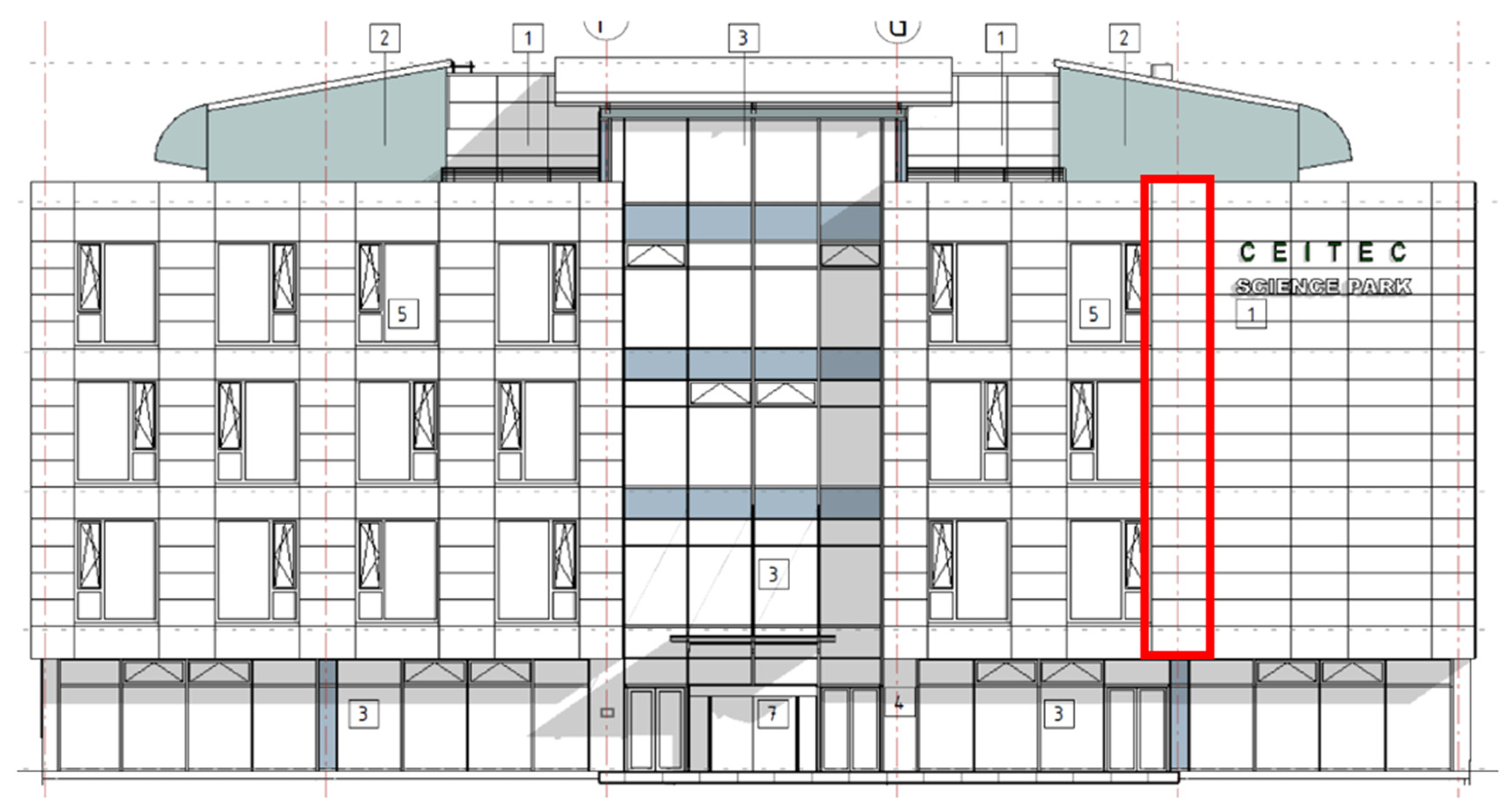
  • The external face area is formed by an external structural façade layer for which numerous materials in a wide range of color variations can be used, with hidden or visible joints in between individual boards. This external layer is fixed to a bearing structure of the external building cladding.
  • The bearing structure of the vertical external envelope is usually formed by a console bearing system made from light metals, steel, or wood.
  • The air layer is located under the vertical external cladding; its thickness is selected to ensure sufficient ventilation.
  • Another layer towards the interior is formed by a thermal insulation layer which must be made from inflammable material, usually from mineral wool. Thermal insulating mats are mounted to the substrate in a contact way by dry technology with the use of anchoring plugs.
  • The thermal insulating layer should be fitted with a windproof foil, which would prevent porous insulators from cooling the external surface by the flowing air on the external side oriented towards the air layer. The windproof foil should be UV radiation resistant and potentially prevent moisturizing of thermal insulation by driven rain.
In Figure 1, there is an example of a façade view with a cut-out marked in red, which shows the place, the area and the height of the continuous ventilated gap. Temperature, humidity and airflow parameters were measured in the mentioned space. At the measurement location, the building has four floors, the building type is administrative, and consists of a reinforced concrete frame. Subsequently, the measured values were used to verify the theoretical model calculated in the FSVM program.

2. Materials and Methods

The bearing structure of the external cladding of the building is located under the thermally insulating layer. The structure is mounted with a bearing console structure to the external façade layer. When using metal bearing elements, there is a risk of thermal bridge occurrence in the area where the steel elements are mounted on the bearing structure. This can be limited by suitable plastic mats.
The aim of this research was to produce a functional model program to calculate the technical parameters of a façade with a ventilated gap which performs fast calculation of the design thermal transmittance U while taking into account the effect of anchoring elements running through the insulation to the façade bearing structure itself.
The CFD (Computational Fluid Dynamics) modeling method, which is used for measuring and understanding dynamics of gases, fluids, losses, velocity and transfer of heat, etc., was used. The CFD method is discussed by, e.g., [23] where a CFD method using a model of a porous medium was applied. Suitable use of the CFD method to predict the behavior of a ventilated gap is based on [24]. The same method is also used for numeric modeling in other articles, e.g., in [5,10,11,17,25], and others.
The simulations include both the terrain extremes and driving forces of thermal buoyancy and the pressure of wind. Simulations with different turbulence models are shown in [25].
The examined calculation algorithm considers the structure composition, material of wall angles and their number, with regard to the weight of a suspended façade. In addition, it considers the effect of a mat including its thickness. In a short time, it calculates the total energy balance of the façade. The software was developed because of the absence of a similar tool in the market, no similar software has been published yet. In order to reach calculation results comparable to the results that the designed software allows reaching, it was necessary to use available CFD software and additionally calculate various characteristics of the façade.
In order to visualize the mentioned calculations in this study, the southeastern part of the façade with an air gap was selected on a building of The South Moravian Innovation Center in Brno (Purkyňova, 621 00 Brno-Medlánky). Brno is located in the temperate climate zone of Central Europe and has a mild continental climate.
Year-round individual air temperatures were measured on this façade (inside the façade, in the ventilated gap, and on the place of installed thermal insulation) on both the bottom part and the upper part of the façade.
The façade is of the exact height of 13.7 m and is covered with cement fiber boards, and the air gap is 122 mm wide. The joint between boards is always 8 mm wide and the boards are of variable heights of 750 mm and 898 mm. Apart from the joints between boards, there is a ventilation grid for the air intake at the bottom and for air exhaust under the attic of the façade.
The overall composition of the wall towards the exterior is (Figure 2):
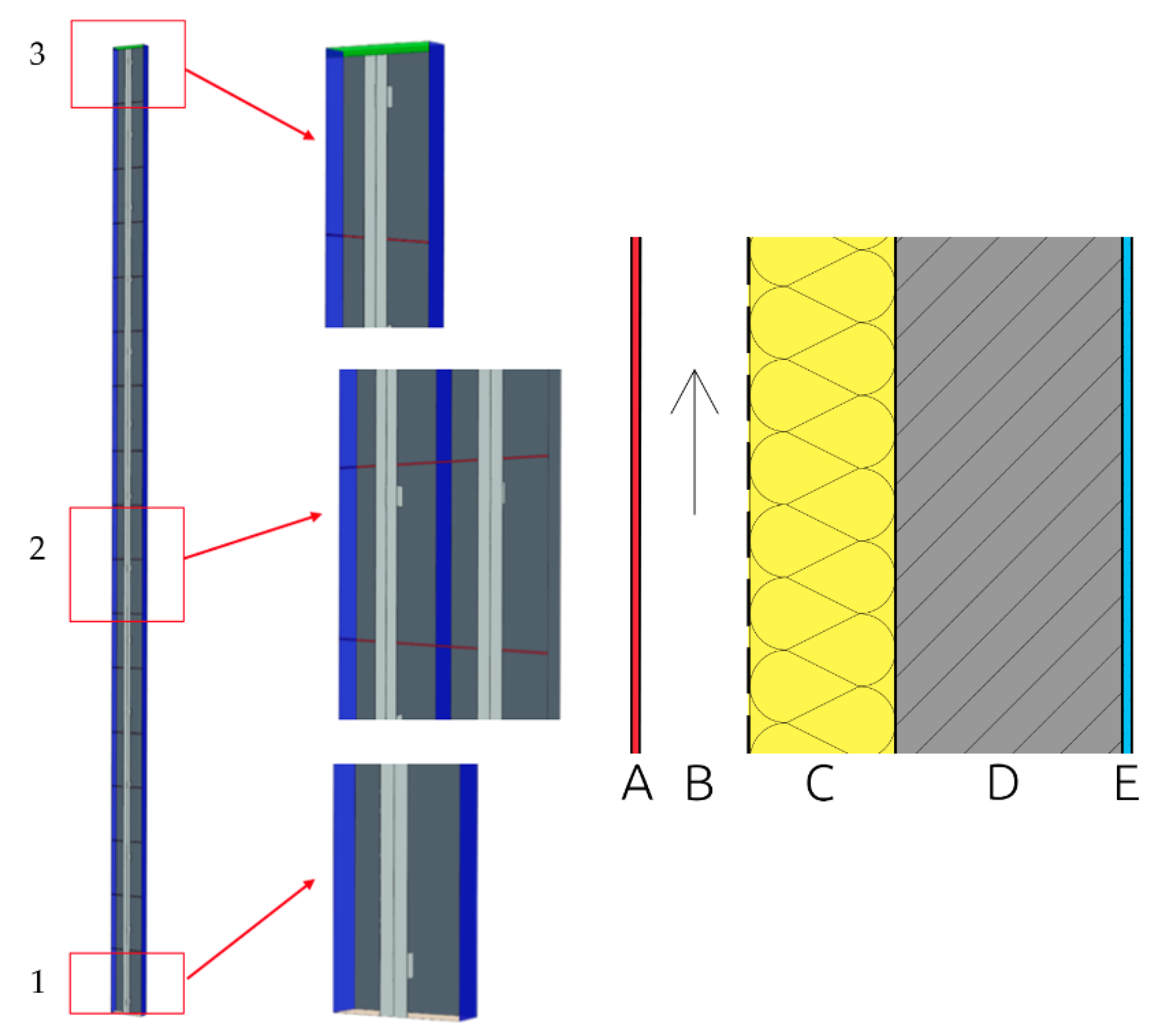
  • 8 mm → cement fiber boards (layer A, color red)
  • 122 mm → air gap (layer B, color white)
  • 160 mm → thermal insulation—mineral wool (layer C, color yellow)
  • 250 mm → reinforced concrete wall (layer D, color gray)
  • 10 mm → interior plaster (layer B, color blue)
Figure 2. Air gap geometry for CFD simulation and composition of the wall. 1 = air inlet at the bottom, 2 = gaps between cladding, 3 = air outlet at the attic, blue = symmetric condition. Right middle picture shows model with symmetry on. The picture also shows the load-bearing elements—the vertical profiles that line the outer lining of the ventilated gap.
Buildings 13 00817 g002
The measured data were used for corrections of partial quantities, e.g., the below-mentioned cladding emissivity Ɛkor. Subsequently, calculation algorithms were verified on the basis of comparisons of the measured data with the measured values.
Compared to the real situation, the following simplified geometry was used in the geometric model:
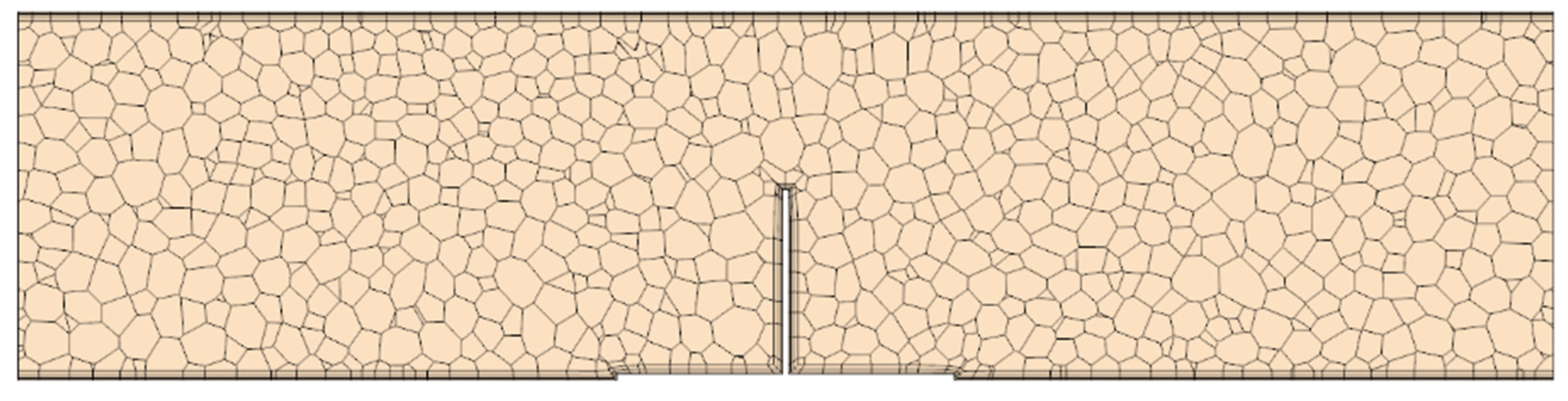
  • intake and exhaust ventilation grids were replaced with a free opening, and the pressure loss is only included numerically,
  • the simulation is dealt with on a symmetric domain; this simplification allows for reducing the time and hardware demands of calculations while maintaining calculation accuracy.
The simulation is conceived as three-dimensional. The final domain has 1,699,694 polyhedral cells. Their target size is 10 mm. The boundary layer has three layers and their overall width is 3 mm. An example of a mesh from the horizontal cross-section is shown in Figure 3.
The solution was also processed analytically in order to compare calculated and measured results. The values obtained from the measurements as well as by the calculation were compared in every step, and the calculation relationships were corrected (e.g., the emissivity of the façade cladding surface Ɛkor, heat transfer αmez, etc.).
An example of a comparison of simulated calculated temperature in the exterior (as one of the main boundary conditions for further detailed calculations) and the measured data in June 2022 is shown in Figure 4. The data for each month were compared in a similar way.
Based on the verified algorithms it was possible to perform annual calculations of partial quantities. The sums by individual hours led to obtaining a complex scheme of heat flows through the façade with a ventilated gap. Examples of selected outcomes are shown in Figure 2, Figure 3, Figure 4 and Figure 5. The building was experimentally assessed based on the performed measurement and with the use of the developed software, where apart from the real condition, other types of façades for the same buildings were considered.
The simulation was designed as a three-dimensional steady non-isothermal process with an ideal gas. The following calculation models were used:
  • Ideal Gas,
  • Coupled Energy,
  • K-Epsilon Turbulence,
  • Gravity.
The simulation was run for two extreme conditions—summer and winter extremes. There are different boundary conditions for each of these conditions. Namely wind velocity in the exterior, heat flows through structures, and airflow through the air gap.
The input values for boundary conditions were obtained from measurements and are applicable for 12:00 summer and winter time of day, as shown in Table 1 and Table 2.

2.1. FSVM Software Development

The program that was developed for calculations of thermal-technical parameters of façades with a ventilated gap is in a form of a freely accessible web application. It performs a fast calculation of the thermal transmittance value U with the effect of anchoring elements running through the insulation to the façade bearing structure itself. The type of cladding is defined by its material and its weight. The calculation algorithm considers the structure composition, material of wall angles and their number, with regard to the weight of a suspended façade. In addition, it contains the effect of the mat including its thickness. The specifications include a quick design of the façade area with the area of spaces for windows and the definition of the exterior and interior design temperature. The result is a design thermal transmittance value U describing heat exchange in steady conditions between the interior and exterior environments, which are separated by an exterior wall with a thermal resistance of R with an adjacent boundary air gap. This thermal transmittance value U includes the effect of all thermal bridges of anchoring elements that are parts of the structure [26].
The current structure of the program FSWM 1.0 includes the application of the algorithm of conduction and transfer of heat from the bearing anchoring angle of the fasade over potential plastic mats and the anchoring system itself into the bearing peripheral structure. Apart from this, the program includes a non-public part (with a freely accessible demo version), where the calculated corrected thermal transmittance can be used for describing thermal-technical properties of the peripheral cladding in the energy performance passport of the building, and at the same time it serves as one of the parameters (boundary condition) for the year-round calculation of energy properties of the façade (heat flow—gain/loss) with a ventilated gap.

2.2. FSVM Modules

The first module calculates the thermal technical parameters of the façade with a ventilated gap and implements a quick calculation of the design coefficient of heat transfer with the influence of anchoring elements passing through the insulation to the actual bearing structure of the façade. The type of cladding is defined by its material and base weight. The program takes a form of a freely accessible web application.
The calculation algorithm takes into account the composition of the structure, the material of the wall angles and their number with respect to the basis weight of the suspended shell, as well as the influence of the base, including its thickness. Part of the assignment is a quick design of the façade area with the area of window openings and the definition of outdoor and indoor design temperature.
The result is a design heat transfer coefficient describing the steady state heat exchange between the indoor and outdoor environment, which are separated by an outer wall of thermal resistance R with an adjacent boundary air layer. This heat transfer coefficient includes the effect of all thermal bridges of the penetrating anchoring elements that are part of the structure.
The second module is non-public and calculates the thermal behavior of a façade with a ventilated gap based on the measured data and simulations. The program works with raw data which are recalculated for specific boundary conditions based on the quasistation method. The output is then the thermal behavior of the façade for a specific location throughout the year.
FSVM is an acronym formed from the initial letters in the Czech language “Façade with Ventilated Gap”. FSVM is a software with two modules. The first public module is used to calculate the heat transfer coefficient for façades with a ventilated gap. The second, non-public module, is used to calculate the annual heat balance of a façade with a ventilated gap. The program in the form of a web application can be viewed online at: http://fasady-5034.rostiapp.cz/ (accessed on 18 December 2022).

2.3. Calculation of Energy Properties of Façade with Ventilated Gap with the Use of FSVM Software

It is a non-public module of the described FSVM software 2.0. The calculations use theoretical approaches that are described above in chapters related to heat sharing by a façade with a ventilated gap see Table 1. The effects mentioned in these chapters form partial boundary conditions that would subsequently, through their synergy, apply to the energy balance between the building’s interior and the exterior environments. In order to include these effects in the calculation, a gradual discreet analytical model was developed, see Table 2. The discretization is based on a temporal division within the calculation of the investigated thermal phenomena in 1-h steps within the whole calendar year [27,28,29]. The basic boundary conditions of the calculation algorithm are shown in Table 3, the actual calculation procedure of the connected quantities is then shown in Table 4.
Furthermore, examples of individual results are presented in the form of comprehensible graphs in order to visualize the mentioned calculations.
Figure 5 shows an obvious impact of natural airflow through the air gap and its crucial impact on the heat flow value (heat loss) of a given façade. Heat flow through a wall with a standard insulation system (green), heat flow through standard cladding with a free air gap (red), and a new cladding system with controlled air flow through an air gap (orange, the flow is limited to the minimum, only flow through leaks in joints of the structure and cladding composition). In the research project of TACR (TACR project is a project funded and monitored by the Technology Agency of the Czech Republic, https://www.tacr.cz/en/technology-agency-of-the-czech-republic/ (accessed on 28 February 2023)), this issue is extensively investigated and potential real technological measures to improve the energy effectiveness of façade systems with a ventilated gap are examined and analyzed.
The impact of the natural airflow through the ventilated gap and its crucial impact on the heat flow value (heat gain) of a given façade is obvious in Figure 6. Natural air convection in a ventilated gap has a positive effect on reducing heat load through the wall in contrast to the traditional contact insulation system. In case the air in the air gap did not flow (e.g., obstacles, window sills, etc.), the heat gain in summer would be unacceptable.
Figure 7 presents an example of a preview of selected courses of calculated quantities over the whole year. Figure 7 shows the value that the inlet air from the air gap may reach in the summer season for a given examined southeastern part of the façade in extreme summer conditions of up to 39 °C at 10 a.m. with the exterior air temperature of +32 °C. In the winter season on sunny days, the temperature of air coming out of the air gap may reach values of 0 °C (exterior air temperature of −10 °C), which is not only caused by solar radiation, but also by the heat loss, or by heat increment from the building interior. Therefore, it is advisable to apply systems of controlling airflow through the air gap (as mentioned above).
Figure 7 shows the boundary conditions of the calculation in a step of one hour and the calculated result presented in hour steps. The individual temperatures are then merged in a graphical representation of the given temperature field.
Performing a similar calculation while not taking into account the cladding and air gap allows us to obtain values of temperatures and heat flows for the standard contact insulation system (the same color as the external layer) ETICS = External Thermal Insulation Composite System.

3. Results

The final values of heat losses and gains by months for a part of the southeastern façade with a height of 13.7 m and width of 1 bm are shown in Table 5.
The results presented in Table 5 show an obvious benefit of the controlled airflow through the ventilated gap in the winter season, and particularly in transitional periods of the year, when there is still low temperature in the exterior, but the solar radiation is sufficient to eliminate the building heat loss. The percentage expression compares differences in heat flows between a standard façade with a ventilated gap (southeastern part of the façade in question) and a smart façade with controlled airflow in winter and transitional periods.
It is an important finding which has a high potential in technological practice for energy savings for the heating of buildings. As shown by the calculations, based on airflow control, the smart façade in orientation southeast shows considerable savings in comparison to standard insulation systems. The savings related to both heat losses (on average up to 40% reduction in heat flow), and heat gains (on average up to 50%).
According to the results of the simulations and the subsequent comparison of energy flows between the south-eastern façade, consisting of ETICS, and the research-supported smart façade with a ventilated gap, Table 5, it can be assumed that the real energy savings for heating in the winter and transitional periods for the smart façade system with a ventilated gap range from 20 to 25%. Regarding the northern façade, the savings will be in the range of about 3 to 5%, taking into account the low glare parameter.

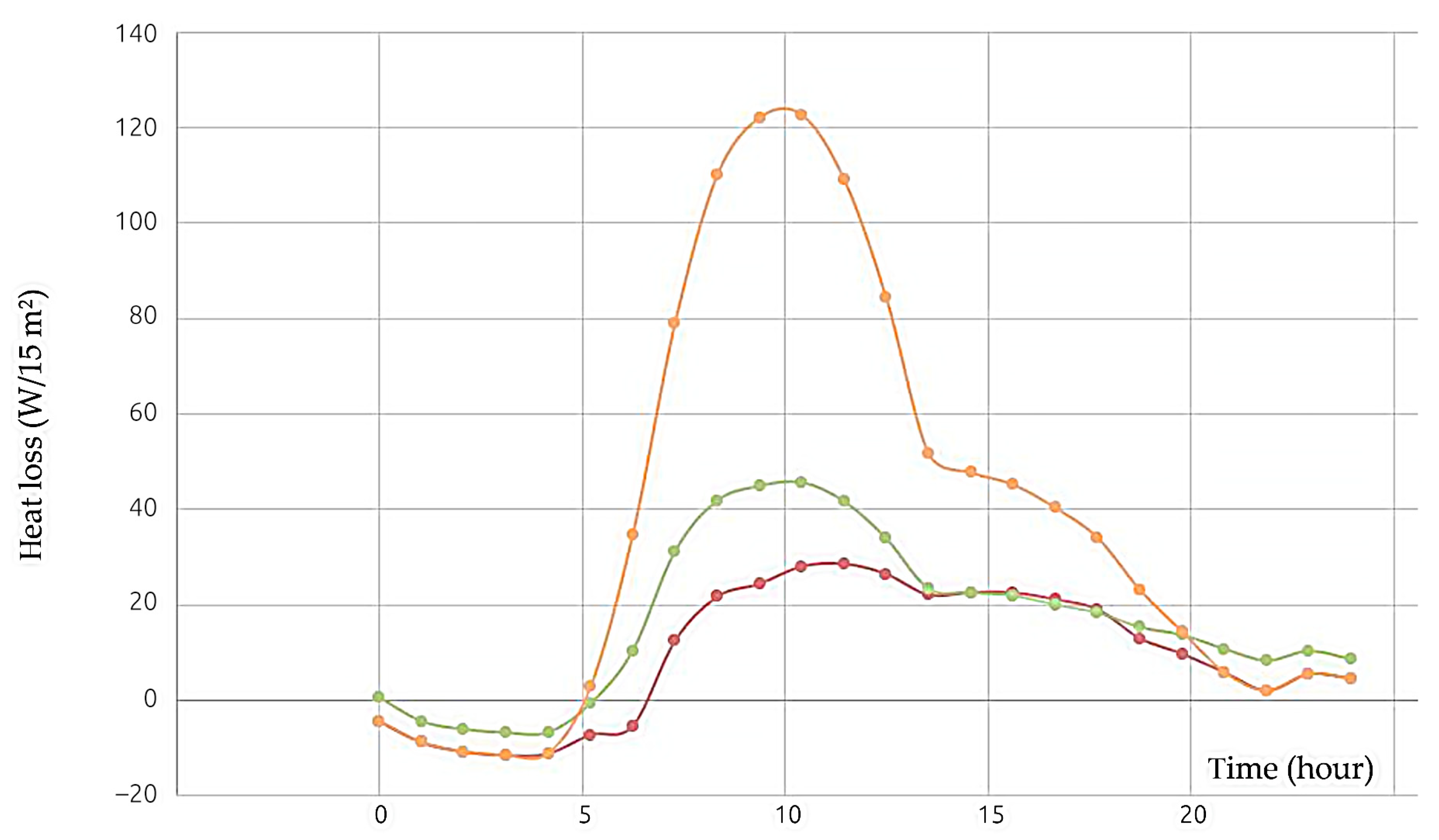
3.1. Results of Summer Extreme Simulation

Based on analytical calculations in the FSVM environment (http://fasady-5034.rostiapp.cz/ (accessed on 28 February 2023)), the day of 21 July 2022 was chosen for the summer extreme. The visualization of streamlines in the ventilated gap and of the temperature field in a vertical cross-section of the façade in the summer temperature extreme is shown in Figure 8.
The visualization of the façade temperature field for a horizontal cross-section at the height of 10 m for the summer extreme is shown in Figure 9.
It is clear from the figure that the highest velocity of airflow is at the highest point and in the outlet of the airflow from the ventilated gap. This is caused by natural air buoyancy and its heating over the external façade envelope along its whole height. The highest air temperature in the air gap is in the highest point of the façade. In addition, there is a noticeable impact of the temperature of the cladding-bearing structure and the shape of the angles bearing this cladding. At the spots of the bearing angles, the air temperature in the air gap increases in comparison to the remaining gap area. In addition, due to the airflow around this warm structure, the airflow in the ventilated gap shows local acceleration.
Figure 10 shows the temperature distribution of air in the air gap along the façade height in the summer extreme, with noticeable linear growth of air temperature along the façade height. Only the air at the façade bottom heats up slower. This is caused both by the proximity of the sucking of exterior cooler air and by the location of the measuring points in the center (axis) of the air gap.
The velocity height profile is rather dispersed, but it is possible to observe a gradual trend of increasing velocity from the façade bottom to the outlet hole, see graph Figure 11 and Figure 12. Figure 9 and Figure 13 show the Coanda effect of airflow attachment to vertical profiles of the façade.

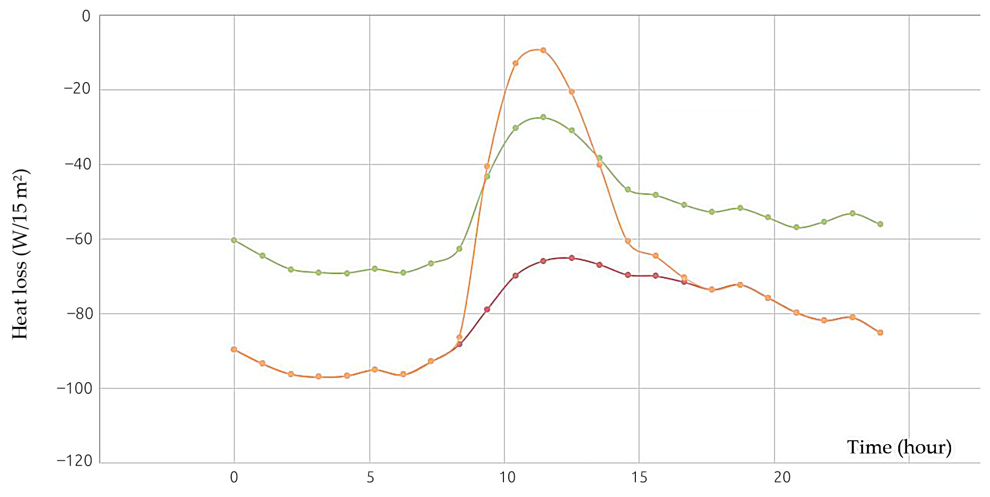
3.2. Simulation Results of Winter Extreme

Based on analytical calculations, January 2022 was chosen as the winter extreme. The simulation results are shown in the Figure 14, Figure 15, Figure 16 and Figure 17. The graphs in Figure 18 and Figure 19 show the temperature and airflow velocity in the ventilated gap for the summer and winter extremes. The record of values from the simulations is plotted through the center of the ventilated gap.
Figure 16 shows again that temperature rises linearly along the height. Only the air at the façade bottom heats up slower. This is caused both by the proximity of the sucking of exterior cold air and by the location of the measuring points in the center (axis) of the air gap.
With regard to airflow from the bottom upwards, the velocity height profile behaves very similarly to airflow in the gap in the summer extreme. Velocity in the air gap is slightly higher in the winter season than in the summer season when due to the warm cladding surface, the potential energy is higher than the kinetic energy of wind around the façade. In the winter season, the impact of wind kinetic energy around the façade prevails over potential energy, i.e., by cool air buoyancy [28].
The results from performed CFD [26]—(Computational Fluid Dynamics—modeling is used for measuring and understanding dynamics of gases, fluids, losses, gains, velocity and transfer of heat, etc.) [30]. The simulations correlate with the calculation results with the help of algorithms using analytical approaches. Thus, it is possible to verify calculation correctness with the use of FSVM software.

4. Discussion

The performed simulation was very effective and showed a good calculation accuracy rate. Similar conclusions were made by authors of publication [31], which discusses individual typological methods and describes their advantages and potential drawbacks.
European standards for designing ventilated structures ETAG 034-1 [32] and ETAG 034-2 [33] specify basic requirements for ventilated structures from the viewpoint of the minimum width of a ventilated gap and dimensions of ventilating holes. In contrast, they fail to consider the effect of orientation to cardinal directions, particularly based on façade sun exposure.
Regarding the efficiency of ventilated façades for removing moisture from the façade and reducing the heat load of buildings, it is necessary to design sun-exposed ventilated façades with at least double values of the minimum parameters specified for ventilated gaps in ETAG [32,33,34]. It appears that any reduction in the cross-section of the façade ventilated joint considerably limits the airflow velocity. The inlet and outlet holes have a major effect on the airflow velocity in the ventilated gap, thus it is advisable to install them with their cross-section close to the cross-section of the ventilated joint. Reflective surfaces in the area of the ventilated joint considerably affect flows of radiation energy between the exterior and interior façade envelope. When selecting individual layers around the ventilated gap, it is necessary to pay attention and stabilize their position not to be able to move or otherwise interfere with the ventilated gap cross-section, since even a local narrowing of the gap would have a considerable effect on airflow. Research and application of findings in the area of the behavior of façades with a ventilated gap is an important part of the construction solution of the building, particularly in the form of the involvement in producing analytical calculation formulas and their subsequent verifications based on the performed detailed measurements and produced CFD models for air flows. The presented results can be used for designing ventilated façade systems with an emphasis on reducing values of heat losses in winter and considerable elimination of heat load in summer. In addition, they have an impact on the summer and winter thermal stability of spaces whose walls form such peripheral structures [26].
Further potential use of the designed software is for assessing thermal-technical properties of façades with a ventilated gap for energy performance passports of buildings and their energy balance. The findings will be used for designing reflective layers in ventilated façades and as study materials for introducing students to functions of ventifaçade structures, particularly with regard to summer overheating of sun-exposed structures and their impact on the internal microclimate in buildings. Based on the obtained results, it is possible to create a so-called smart façade in the next step of development that will react in real-time to temperature and air humidity conditions in the ventilated gap. By controlling the airflow in the ventilated gap, this smart façade can correct the heat flows from and into the building all year round so that they are as low as possible. More knowledge in the field of thermal profiles through a ventilated gap and airflow velocities is related to temperature and wind for cases specified in this work.
The results can be used for:
  • Assessing thermal-technical properties…
  • Designing reflective layers…
  • Knowledge of thermal profiles…
  • In their article, the authors show in the case of façade constructions with a ventilated gap, a possibility to significantly reduce heat flows between the interior and exterior of the building with inexpensive technical adjustments. The presented percentage reduction of heat losses in winter assumes a certain reduction in the performance of heat sources in these buildings and thus also their energy demand in the area of heating. When using airflow control through a ventilated gap, real energy savings for heating can be expected in the range of 5 to 25%, according to the simulations performed, depending on the global orientation of a particular façade.

5. Conclusions

The research presents a basic assumption for understanding heat transfer in façade structures with a ventilated gap, shows potential for further development of the so-called “Smart façade with ventilated gap”, shows potential for research and development of airflow in a ventilated gap and other applications reducing the energy performance of buildings with these structures. The research further presents a model application in the field of airflow in ventilated gaps of façade structures and experimental measurements in ventilated façade structures. The research results can be used in the field of ventilated façades, particularly for bigger structures, high-rise buildings, corners, etc. Furthermore, they can be used for low-emission layers in ventilated façades and their further development in terms of material and construction.

Author Contributions

Conceptualization, A.R.; methodology, A.R. and P.U.; software, validation, M.F.; P.U. and J.V. (Jakub Vrána); formal analysis, O.N.; investigation, A.R.; resources, P.U.; writing—original draft preparation, D.S. and J.V. (Jan Vystrčil); writing—review and editing, E.Š.; visualization, P.U.; supervision, M.N.; project administration, A.R.; funding acquisition, A.R. All authors have read and agreed to the published version of the manuscript.

Funding

This research was funded by projects FAST-S-22-7788 Advanced Systems of the Environment Technology and Energy Performance of Buildings and FW03010062 Smart Façade Systems with Energy-Optimized Properties. Our sincere gratitude for funding and development in the field of ventilated façades.

Institutional Review Board Statement

Study did not require ethical approval.

Informed Consent Statement

Not applicable.

Data Availability Statement

Data is available on request due to restrictions such as data protection or ethical reasons. The data presented in this study are available on request from the corresponding author. Data are not publicly available due to commercial use.

Conflicts of Interest

The authors declare no conflict of interest.

References

  1. Hejlíčková, L. Rozbor a porovnání předvěšených provětrávaných fasádních systémů. Master Thesis, Západočeská univerzita v Plzni, Pilsen, Czech Republic, 2019. Available online: https://dspace5.zcu.cz/bitstream/11025/37538/1/DP_Hejlickova_2019.pdf (accessed on 10 May 2021).
  2. Šagát, E. Větrání Obvodových Plášťů Budov z Hlediska Konstrukčních Detailů Pasivních a Nízkoenergetických Domů; Vysoké Učení Technické v Brně, Fakulta Stavební: Brno, Czech Republic, 2017. [Google Scholar]
  3. Sanjuan, C.; Sánchez, M.N.; del Rosario Heras, M.; Blanco, E. Experimental analysis of natural convection in open joint ventilated fagades with 2D PIV. Build. Environ. 2011, 46, 2314–2325. [Google Scholar] [CrossRef]
  4. Shameri, M.A.; Alghoul, M.A.; Sopian, K.; Zain, M.F.M.; Elayeb, O. Perspectives of double skin facade systems in buildings and energy saving. Renew. Sustain. Energy Rev. 2011, 15, 1468–1475. [Google Scholar] [CrossRef]
  5. Safer, N.; Woloszyn, M.; Roux, J.J. Three-dimensional simulation with a CFD tool of the airflow phenomena in single floor double-skin facade equipped with a venetian blind. Sol. Energy 2005, 79, 193–203. [Google Scholar] [CrossRef]
  6. Iyi, D.; Hasan, R.; Penlington, R.; Underwood, C. Double skin facade: Modelling technique and influence of Venetian blinds on the airflow and heat transfer. Appl. Therm. Eng. 2014, 71, 219–229. [Google Scholar] [CrossRef] [Green Version]
  7. Pasut, W.; De Carli, M. Evaluation of various CFD modelling strategies in predicting airflow and temperature in a naturally ventilated double skin facade. Appl. Therm. Eng. 2012, 37, 267–274. [Google Scholar] [CrossRef] [Green Version]
  8. Zöllner, A.; Winter, E.; Viskanta, R. Experimental studies of combined heat transfer in turbulent mixed convection fluid flows in double-skin-facades. Int. J. Heat Mass Transf. 2002, 45, 4401–4408. [Google Scholar] [CrossRef]
  9. Duarte, N.; Naylor, D.; Oosthuizen, P.H.; Harrison, S.J. An interferometric study of free convection at a window glazing with a heated venetian blind. HVACR Res. 2001, 7, 169–184. [Google Scholar] [CrossRef]
  10. Jiru, T.E.; Tao, Y.; Haghighat, F. Airflow and heat transfer in double skin facades. Energy Build. 2011, 43, 2760–2766. [Google Scholar] [CrossRef]
  11. Manz, H.; Schaelin, A.; Simmler, H. Airflow patterns and thermal behavior of mechanically ventilated glass double facades. Build. Environ. 2004, 39, 1023–1033. [Google Scholar] [CrossRef]
  12. Seferis, P.; Strachan, P.; Dimoudi, A.; Androutsopoulos, A. Investigation of the performance of a ventilated wall. Energy Build. 2011, 43, 2167–2178. [Google Scholar] [CrossRef]
  13. Guillén, I.; Gómez-Lozano, V.; Fran, J.M.; López-Jiménez, P.A. Thermal behavior analysis of different multilayer facade: Numerical model versus experimental prototype. Energy Build. 2014, 79, 184–190. [Google Scholar] [CrossRef]
  14. Pourghorban, A.; Asoodeh, H. The impacts of advanced glazing units on annual performance of the Trombe wall systems in cold climates. Sustain. Energy Technol. Assess. 2022, 51, 101983. [Google Scholar] [CrossRef]
  15. Pomaranzi, G.; Daniotti, N.; Schito, P.; Rosa, L.; Zasso, A. Experimental assessment of the effects of a porous double skin facade system on cladding loads. J. Wind. Eng. Ind. Aerodyn. 2020, 196, 104019. [Google Scholar] [CrossRef]
  16. Hu, G.; Hassanli, S.; Kwok, K.C.; Tse, K.-T. Wind-induced responses of a tall building with a double-skin facade system. J. Wind. Eng. Ind. Aerodyn. 2017, 168, 91–100. [Google Scholar] [CrossRef]
  17. Nasrollahi, N.; Ghobadi, P. Field measurement and numerical investigation of natural cross-ventilation in high-rise buildings; Thermal comfort analysis. Appl. Therm. Eng. 2022, 211, 118500. [Google Scholar] [CrossRef]
  18. Georgakis, G.; Santamouris, M. Experimental investigation of air flow and temperature distribution in deep urban canyons for natural ventilation purposes. Energy Build. 2006, 38, 367–376. [Google Scholar] [CrossRef]
  19. Wen, Y.; Guo, Q.; Xiao, P.; Ming, T. The Impact of Opening Sizing on the Airflow Distribution of Double skin Facade. Procedia Eng. 2017, 205, 4111–4116. [Google Scholar] [CrossRef]
  20. Balocco, C. A simple model to study ventilated facades energy performance. Energy Build. 2002, 34, 469–475. [Google Scholar] [CrossRef]
  21. Patania, F.; Gagliano, A.; Nocera, F.; Ferlito, A.; Galesi, A. Thermofluid-dynamic analysis of ventilated facades. Energy Build. 2010, 42, 1148–1155. [Google Scholar] [CrossRef]
  22. Iltegro: Fasádní Systémy. Available online: http://www.iltegro.cz/ (accessed on 19 May 2021).
  23. Zeng, Y.; Li, X.; Li, C.; Zhu, Y. Modeling ventilation in naturally ventilated double-skin fagade with a venetian blind. Build. Environ. 2012, 57, 1–6. [Google Scholar] [CrossRef]
  24. Manz, H. Numerical simulation of heat transfer by natural convection in cavities of Facade elements. Energy Build. 2003, 35, 305–311. [Google Scholar] [CrossRef]
  25. Zhang, Z.; Zhang, W.; Zhai, Z.; Chen, Q. Evaluation of various turbulence models in predicting airflow and turbulence in enclosed environments by CFD: Part 2—comparison with experimental data from literature. HVACR Res. 2007, 13, 871–886. [Google Scholar] [CrossRef]
  26. Hájek, J. Modelování s Využitím CFD, 1st ed.; VUT Fakulta Strojní: Brno, Czech Republic, 2008. [Google Scholar]
  27. ČSN 73 0540-2; Tepelná Ochrana Budov. Část 2: Požadavky. ÚNMZ: Praha, Czech Republic, 2011; p. 56.
  28. ČSN 73 0540-3; Tepelná Ochrana Budov. Část 3: Funkční Požadavky. ÚNMZ: Praha, Czech Republic, 2015.
  29. ČSN 73 0540-4; Tepelná Ochrana Budov. Část 4: Výpočtové Metody. ÚNMZ: Praha, Czech Republic, 2005; p. 60.
  30. Dai, B.; Liu, C.; Liu, S.; Wang, D.; Wang, Q.; Zou, T.; Zhou, X. Life cycle techno-enviro-economic assessment of dual-temperature evaporation transcritical CO2 high-temperature heat pump systems for industrial waste heat recovery. Appl. Therm. Eng. 2023, 219, 119570. [Google Scholar] [CrossRef]
  31. de Gracia, A.; Castell, A.; Navarro, L.; Oró, E.; Cabeza, L.F. Numerical modelling of ventilated facades: A review. Renew. Sustain. Energy Rev. 2013, 22, 539–549. [Google Scholar] [CrossRef]
  32. ETAG 034-1; Ventilated Cladding Kits Comprising Cladding Components and Associated Fixings. European Organisation for Technical Approvals: Brussels, Belgium, 2012; p. 98.
  33. ETAG 034-2; Cladding Kits Comprising Cladding Components, Associated Fixings, Subframe and Possible Insulation Layer. European Organisation for Technical Approvals: Brussels, Belgium, 2012; p. 29.
  34. ETAG 034; Guideline for European Technical Approval of Kits for External Wall Cladding: Part I: Ventilated Cladding Kits Comprising Cladding Components and Associated Fixings. European Organisation for Technical Approvals: Brussels, Belgium, 2012. Available online: http://www.sgpstandard.cz/editor/files/stav_vyr/dok_es/eta/etag/034_1_en.pdf (accessed on 10 December 2022).
Figure 1. Measured and numerically evaluated faade. Façade part in question is marked red, façade height as well as air gap is approx. 13.7 m.
Buildings 13 00817 g001
Figure 3. Mesh in horizontal cross-section through air gap.
Buildings 13 00817 g003
Figure 4. Example of course of calculated (red) and measured air temperature in exterior (blue), together with example of measured air temperature in area of air gap in bottom part of façade (green), upper part of façade (yellow), as of 21 July 2022.
Buildings 13 00817 g004
Figure 5. Example of simulated course of airflow from interior to exterior and their comparison as of 21 January 2022 for dimension of a southeast façade strip of 15 m height and 1 bm width. Façade with traditional contact insulation system (green), façade without air flow control through a ventilated gap (red) and smart façade with airflow control through a ventilated gap (orange).
Buildings 13 00817 g005
Figure 6. Example of simulated course of airflow from exterior to interior and their comparison as of 21 July 2022. Façade with traditional contact insulation system (green), façade without air flow control through a ventilated gap (red) and smart façade with airflow control through a ventilated gap (orange).
Buildings 13 00817 g006
Figure 7. Example of year-round calculated temperature course in one-hour increments for outlet air temperatures from ventilated gap tvzmvyst (orange), temperature of outer face of Tepob cladding (purple) and corrected internal air temperature in tikorig building (blue) for entire monitored year for selected southeast façade.
Buildings 13 00817 g007
Figure 8. (a) Visualization of streamlines in ventilated gap—3D view, (b) Visualization of temperature field in façade vertical cross section in summer temperature extreme.
Buildings 13 00817 g008
Figure 9. Visualization of façade temperature field—horizontal cross-section at height of 10 m summer extreme.
Buildings 13 00817 g009
Figure 10. Graph of temperature distribution of air in air gap along façade height in summer extreme.
Buildings 13 00817 g010
Figure 11. Visualization of velocity field in air gap in façade vertical cross-section summer extreme.
Buildings 13 00817 g011
Figure 12. Graph of velocity distribution in ventilated gap along façade height summer extreme.
Buildings 13 00817 g012
Figure 13. Velocity field—horizontal cross section at height of 10 m summer extreme.
Buildings 13 00817 g013
Figure 14. (a) Visualization of streamlines in ventilated gap of façade—3D view. (b) Visualization of temperature field in façade vertical cross section in winter temperature extreme.
Buildings 13 00817 g014
Figure 15. Visualization of façade temperature field—horizontal cross-section at height of 10 m winter extreme.
Buildings 13 00817 g015
Figure 16. Velocity field—horizontal cross section at height of 10 m winter extreme.
Buildings 13 00817 g016
Figure 17. Visualization of velocity field in air gap in façade vertical cross section winter extreme.
Buildings 13 00817 g017
Figure 18. Projection and graph of temperature distribution of air in air gap along façade height in winter extreme.
Buildings 13 00817 g018
Figure 19. Graph of velocity distribution in ventilated gap along façade height winter extreme.
Buildings 13 00817 g019
Table 1. Boundary conditions of summer extreme in July 2022.
wind velocity in exterior1.38m/s
air flow through gap100.4m3/h per meter of width
air temperature in exterior29.9°C
heat flow from exterior10.7W/m2
heat flow from interior−0.82W/m2
Table 2. Boundary conditions of summer extreme in January 2022.
wind velocity in exterior1.73m/s
air flow through gap125.5m3/h per meter of width
air temperature in exterior−8.1°C
heat flow from exterior0W/m2
heat flow from interior6.2W/m2
Table 3. Main boundary conditions are defined as follows.
SymbolParameterUnit
orientation of the investigated façade to cardinal directions (longitude, latitude, façade azimuth, façade altitude, etc.)
Isolar constants for calculation of direct and diffuse radiation (implicitly the value of 1370 is applied)W/m2
geometric properties of the façade and the ventilated gap (height, width of 1 bm, properties of air inlet and outlet of the ventilated gap, etc.)
Ukorigcorrected thermal transmittance of the façade including anchoring point elements of the façadeW/m2·K
thermal-technical properties of the cladding material (medium emissivity, color, thickness, specific heat capacity, thermal conductivity, etc.
definition of thermal boundary conditions of the interior, so-called corrected interior temperature, based on a season
tikoriginterior air temperature is entered for a selected month over a time period of one day°C
tethermal boundary conditions of the exterior over a whole season, a method of harmonic fluctuation of temperature for every day in a given month and year°C
definition of ventilated area and air flow therefrom at the bottom and upper part of the façade
npair permeability (leak) of the used type of cladding (percentage correction),%
and others
Table 4. Calculation itself is then based on determining.
SymbolParameterUnit
hheight of the sun above the horizon°
aazimuth of the sun°
cos(Φ)numeric expression of an angle between the normal of the sun-exposed surface and direction of sun rays for a vertical wall°
Idirect incident sun radiation in direction of sun raysW/m2
Iddiffuse incident sun radiationW/m2
Ipdirect incident sun radiation onto an azimuth-oriented wallW/m2
Iototal sun radiation incident onto an azimuth-oriented wall IoW/m2
trequal sun temperature onto an azimuth-oriented wall°C
Ɛkorcorrected emissivity by time (month) of calculation(-)
αkorcorrected heat transfer at the exterior side of the envelope by time (month) of calculationW/m2·K
Tepobtemperature of the exterior side of cladding onto an azimuth-oriented wall°C
αmezheat transfer at free flow in the gapW/m2·K
Umezheat transmittance of cladding at variable αmezW/m2·K
Qradheat gain from overall radiation on façade width 1 bm for a given overall façade height hW
vd and vhwind velocity in the vicinity of the building façade based on wind aream/s
tvzmvystoutlet air temperatures from the air gap in between the cladding and wall thermal insulation°C
Qzheat flow from the interior of the building into the air gap (loss symbol −, gain symbol +) with Ukorig of bearing structure along the whole façade height h per 1 bm of façade with a delayW
Qyear-round thermal balance by months of the bearing structure along the whole façade height h per 1 bm of façadekWh
Table 5. Comparison of calculated total values of heat flows for the façade type in question.
Month in YearETICS Façade
(kWh/Month)
Existing Ventilated Façade
(kWh/Month)
Smart Façade with Ventilated Gap (kWh/Month)Percentage Expression of Reduced Heat Flow by Smart Façade (%)
1−41.75−54.98−47.0214
2−24.41−35.52−28.4520
3−7.95−20.137.08135
4−1.66−12.09−12.090
54.02−7.01−7.010
67.240.980.980
712.276.096.090
817.3511.2311.230
911.956.436.430
10−1.73−9.416.44168
11−15.79−24.55−13.1746
12−36.38−46.75−41.7311
Disclaimer/Publisher’s Note: The statements, opinions and data contained in all publications are solely those of the individual author(s) and contributor(s) and not of MDPI and/or the editor(s). MDPI and/or the editor(s) disclaim responsibility for any injury to people or property resulting from any ideas, methods, instructions or products referred to in the content.

