

Numerical Simulation of the Performance of Self-Healing Concrete in Beam Elements

Abstract
:1. Introduction
1.1. Research Gaps and Future Perspective
- Finite element study carried out with an advanced and reliable numerical simulation platform;
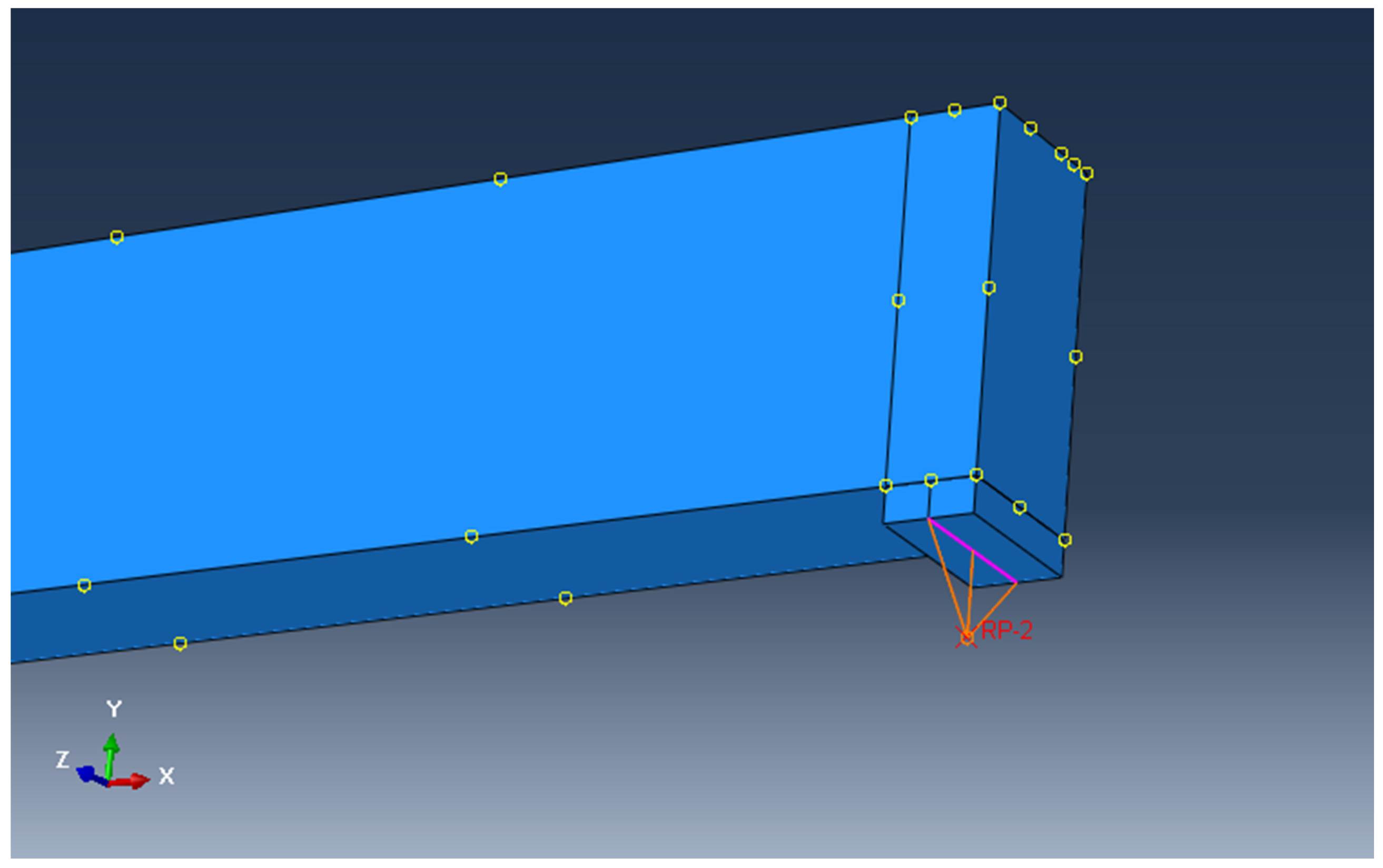
- Constitutive models, including details of the material properties of ordinary concrete, the reinforcement, and the SHC, in addition to the model configuration showing elements and meshing types;
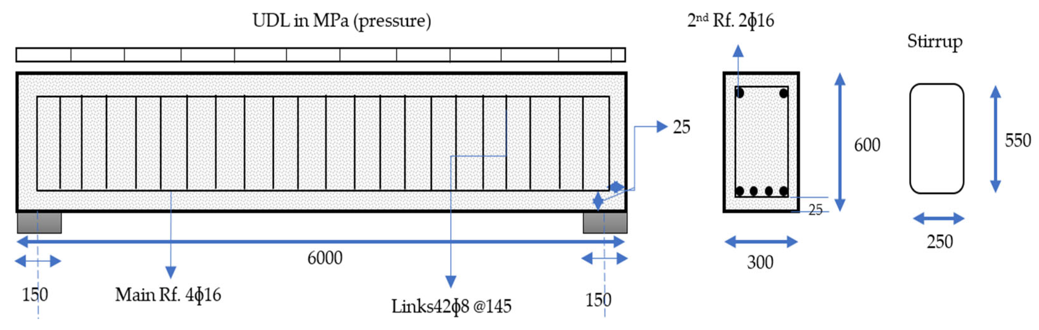
- Modeling the reference beam (reinforced concrete beam);
- Validating the deflection obtained from simulation with the theoretical formula;
- Modeling the SHC beams.
1.2. Previous Work on Mechanical Properties of SHC
2. Materials and Methods
2.1. Constitutive Models
2.1.1. Material Properties of Concrete and Steel Reinforcement
2.1.2. Numerical Model for the Structural Analyses
2.2. Reference Beam Modeling
2.3. Validation of the Abaqus model through Comparisons with Theoretical Formulations
2.4. SHC Beam Modeling
3. Results
4. Discussion
5. Conclusions
- The addition of SHC improved the overall performance of the structural beam;
- Most significant improvements in the SHC models were achieved in yield strength when lower loads were considered;
- The small cracks that formed at lower loads seemed to be healed, since the increases in overstrength at these loads were significant (as much as 47% higher than the original strength);
- There was good indication of the effectiveness of the SHC at excessive loads, such as cracking and ultimate loads;
- The maximum strength of the SHC beams was higher than the reference beam, with an increase in overstrength of only 18% compared to the original.
6. Further Research
Author Contributions
Funding
Institutional Review Board Statement
Informed Consent Statement
Data Availability Statement
Acknowledgments
Conflicts of Interest
References
- Van Belleghem, B.; van den Heede, P.; Van Tittelboom, K.; De Belie, N.D. Quantification of the Service Life Extension and Environmental Benefit of Chloride Exposed Self-Healing Concrete. Materials 2016, 10, 5. [Google Scholar] [CrossRef] [Green Version]
- Van den Heede, P.; De Belie, N.; Pittau, F.; Habert, G.; Mignon, A. Life Cycle Assessment of Self-Healing Engineered Cementitious Composite (SH-ECC) Used for the Rehabilitation of Bridges. Available online: https://core.ac.uk/display/188629730 (accessed on 20 May 2022).
- van den Heede, P.; Mignon, A.; Habert, G.; De Belie, N. Cradle-to-gate life cycle assessment of self-healing engineered cementitious composite with in-house developed (semi-)synthetic superabsorbent polymers. Cem. Concr. Compos. 2018, 94, 166–180. [Google Scholar] [CrossRef]
- Garces, J.I.T.; Dollente, I.J.; Beltran, A.B.; Tan, R.R.; Promentilla, M.A.B. Life cycle assessment of self-healing geopolymer concrete. Clean. Eng. Technol. 2021, 4, 100147. [Google Scholar] [CrossRef]
- Ramagiri, K.; Chintha, R.; Bandlamudi, R.; De Maeijer, P.K.; Kar, A. Cradle-to-Gate Life Cycle and Economic Assessment of Sustainable Concrete Mixes—Alkali-Activated Concrete (AAC) and Bacterial Concrete (BC). Infrastructures 2021, 6, 104. [Google Scholar] [CrossRef]
- Li, V.C.; Herbert, E. Robust self-healing concrete for sustainable infrastructure. J. Adv. Concr. Technology 2012, 10, 207–218. [Google Scholar] [CrossRef] [Green Version]
- Van Tittelboom, K.; De Belie, N. Self-Healing in Cementitious Materials—A Review. Materials 2013, 6, 2182–2217. [Google Scholar] [CrossRef] [Green Version]
- Theodoridou, M.; Harbottle, M. Biological Self-Healing for the Protection of Cultural Heritage Stone Structures. Available online: https://confit.atlas.jp/guide/event-img/jpgu2018/MIS02-P05/public/pdf?type=in (accessed on 24 December 2022).
- Vucetic, S.; Miljevic, B.; Sovljanski, O.; van der Bergh, J.M.; Markov, S.; Hirsenberger, H.; Malesevic, M.T.; Ranogajec, J. Functional mortars for conservation of cultural heritage structures. IOP Conf. Series: Mater. Sci. Eng. 2020, 949, 12091. [Google Scholar] [CrossRef]
- Booth, P.; Jankovic, L. Novel biodesign enhancements to at-risk traditional building materials. Front. Built Environ. 2022, 8. [Google Scholar] [CrossRef]
- Arnold, D. Self-healing concrete. Ingenia Mag. 2011, 46, 39–43. [Google Scholar]
- Sunakh Zabanoot, M.S. Review of Autogenous and Autonomous self-Healing Concrete Technologies for Marine Environments. High Perform. Optim. Des. Struct. Mater. IV 2020, 196, 31. [Google Scholar] [CrossRef]
- Albuhairi, D.; Di Sarno, L. Low-Carbon Self-Healing Concrete: State-of-the-Art, Challenges and Opportunities. Buildings 2022, 12, 1196. [Google Scholar] [CrossRef]
- Yang, S.; Aldakheel, F.; Caggiano, A.; Wriggers, P.; Koenders, E. A Review on Cementitious Self-Healing and the Potential of Phase-Field Methods for Modeling Crack-Closing and Fracture Recovery. Materials 2020, 13, 5265. [Google Scholar] [CrossRef]
- Freeman, B.L.; Bonilla-Villalba, P.; Mihai, I.C.; Alnaas, W.F.; Jefferson, A.D. A specialised finite element for simulating self-healing quasi-brittle materials. Adv. Model. Simul. Eng. Sci. 2020, 7, 32. [Google Scholar] [CrossRef]
- Mauludin, L.M.; Zhuang, X.; Rabczuk, T. Computational modeling of fracture in encapsulation-based self-healing concrete using cohesive elements. Compos. Struct. 2018, 196, 63–75. [Google Scholar] [CrossRef]
- Huang, H.; Ye, G. Simulation of self-healing by further hydration in cementitious materials. Cem. Concr. Compos. 2012, 34, 460–467. [Google Scholar] [CrossRef]
- Zhelyazov, T. Numerical Simulation of the Response of Concrete Structural Elements Containing a Self-Healing Agent. Materials 2022, 15, 1233. [Google Scholar] [CrossRef]
- Hermawan, H.; Minne, P.; Serna, P.; Gruyaert, E. Understanding the Impacts of Healing Agents on the Properties of Fresh and Hardened Self-Healing Concrete: A Review. Processes 2021, 9, 2206. [Google Scholar] [CrossRef]
- Guzlena, S.; Sakale, G. Self-healing concrete with crystalline admixture—A review. IOP Conf. Ser. Mater. Sci. Eng. 2019, 660, 12057. [Google Scholar] [CrossRef]
- Reddy, T.C.S.; Ravitheja, A. Macro mechanical properties of self healing concrete with crystalline admixture under different environments. Ain Shams Eng. J. 2019, 10, 23–32. [Google Scholar] [CrossRef]
- Di Luzio, G.; Ferrara, L.; Krelani, V. Numerical modeling of mechanical regain due to self-healing in cement based composites. Cem. Concr. Compos. 2018, 86, 190–205. [Google Scholar] [CrossRef]
- Guo, S.; Samir, C. MAT152-1 CSCE Annual Conference Growing with Youth -Croître Avec Les Jeunes Laval (Greater Montreal) Self-Healing Concrete: A Critical Review. 2019. Available online: https://www.csce.ca/elf/apps/CONFERENCEVIEWER/conferences/2019/pdfs/PaperPDFVersion_152_0423094222.pdf (accessed on 12 June 2019).
- Gilford, J.; Hassan, M.M.; Rupnow, T.; Barbato, M.; Okeil, A.M.; Asadi, S. Dicyclopentadiene and Sodium Silicate Microencapsulation for Self-Healing of Concrete. J. Mater. Civ. Eng. 2014, 26, 886–896. [Google Scholar] [CrossRef]
- Abaqus/Standard—Simulation of Static and Low Speed Dynamic Events. Available online: https://www.3ds.com/products-services/simulia/products/abaqus/abaqusstandard/ (accessed on 26 December 2022).
- Öztürk, H.; Demir, A.; Caglar, N. Eurocode 2: Design of Concrete Structures|Eurocodes: Building the Future. Effect of Support Conditions on Behavior of Reinforced Concrete Short Beams. 2016. Available online: https://eurocodes.jrc.ec.europa.eu/EN-Eurocodes/eurocode-2-design-concrete-structures (accessed on 1 January 2022).
- ACI Committee (Ed.) Building Code Requirements for Structural Concrete (ACI318–95) and Commentary (ACI318R-95); American Concrete Institute: Farmington Hills, MI, USA, 1995. [Google Scholar]
- Lubliner, J.; Oliver, J.; Oller, S.; Oñate, E. A Plastic-Damage Model for Concrete. Int. J. Solids Struct. 1989, 25, 299–326. Available online: https://www.semanticscholar.org/paper/A-plastic-damage-model-for-concrete-Lubliner-Oliver/4d383d4dc71548595d099fe7ec8513c1e0023b0d (accessed on 3 February 2023). [CrossRef]
- Lee, J.; Fenves, G.L. Plastic-Damage Model for Cyclic Loading of Concrete Structures. J. Eng. Mech. 1998, 124, 892–900. [Google Scholar] [CrossRef]
- Lee, S.-H.; Abolmaali, A.; Shin, K.-J.; Lee, H.-D. ABAQUS modeling for post-tensioned reinforced concrete beams. J. Build. Eng. 2020, 30, 101273. [Google Scholar] [CrossRef]
- George, J.; Kalyana Rama, J.S.; Siva Kumar, M.V.N.; Vasan, A. Behavior of Plain Concrete Beam subjected to Three Point Bending using Concrete Damaged Plasticity (CDP) Model. Mater. Today Proc. 2017, 4, 9742–9746. [Google Scholar] [CrossRef]
- Labibzadeh, M.; Zakeri, M.; Shoaib, A.A. A new method for CDP input parameter identification of the ABAQUS software guaranteeing uniqueness and precision. Int. J. Struct. Integr. 2017, 8, 264–284. [Google Scholar] [CrossRef]
- Vijay, K.; Murmu, M. Self-repairing of concrete cracks by using bacteria and basalt fiber. SN Appl. Sci. 2019, 1, 1344. [Google Scholar] [CrossRef] [Green Version]
- Mirshahmohammad, M.; Rahmani, H.; Maleki-Kakelar, M.; Bahari, A. Effect of sustained service loads on the self-healing and corrosion of bacterial concretes. Constr. Build. Mater. 2022, 322, 126423. [Google Scholar] [CrossRef]
- Giannaros, P.; Kanellopoulos, A.; Al-Tabbaa, A. Sealing of cracks in cement using microencapsulated sodium silicate. Smart Mater. Struct. 2016, 25, 84005. [Google Scholar] [CrossRef]
- Ravitheja, A.; Reddy, T.C.S.; Sashidhar, C. Self-Healing Concrete with Crystalline Admixture—A Review. J. Wuhan Univ. Technol. Sci. Ed. 2019, 34, 1143–1154. [Google Scholar] [CrossRef]


| Concrete | C25/30 |
|---|---|
| fck (MPa) | 25 |
| fcm (MPa) | 33 |
| Ec (MPa) | 31,476 |
| fctm (MPa) | 2.56 |
| v | 0.2 |
| Steel | B500C |
|---|---|
| fs (MPa) | 500 |
| Ec (MPa) | 200,000 |
| v | 0.3 |
| Ψ (Dilatation Angle) | e (Eccentricity) | (fb0/fc0) | Kc | Viscosity |
|---|---|---|---|---|
| 36° | 0.1 | 1.16 | 0.667 | 0 |
| Concrete | C25/30 |
|---|---|
| fck healed (MPa) | 25 |
| E healed (MPa) | 40,540 |
| fctm healed (MPa) | 4 |
| v Density, ρ | 0.2 2.5 × 10⁻⁹ |
| Yield Point | Cracking Point | Max Point | ||||
|---|---|---|---|---|---|---|
| Model | Deflection (mm) | Load (kN) | Deflection (mm) | Load (kN) | Deflection (mm) | Load (kN) |
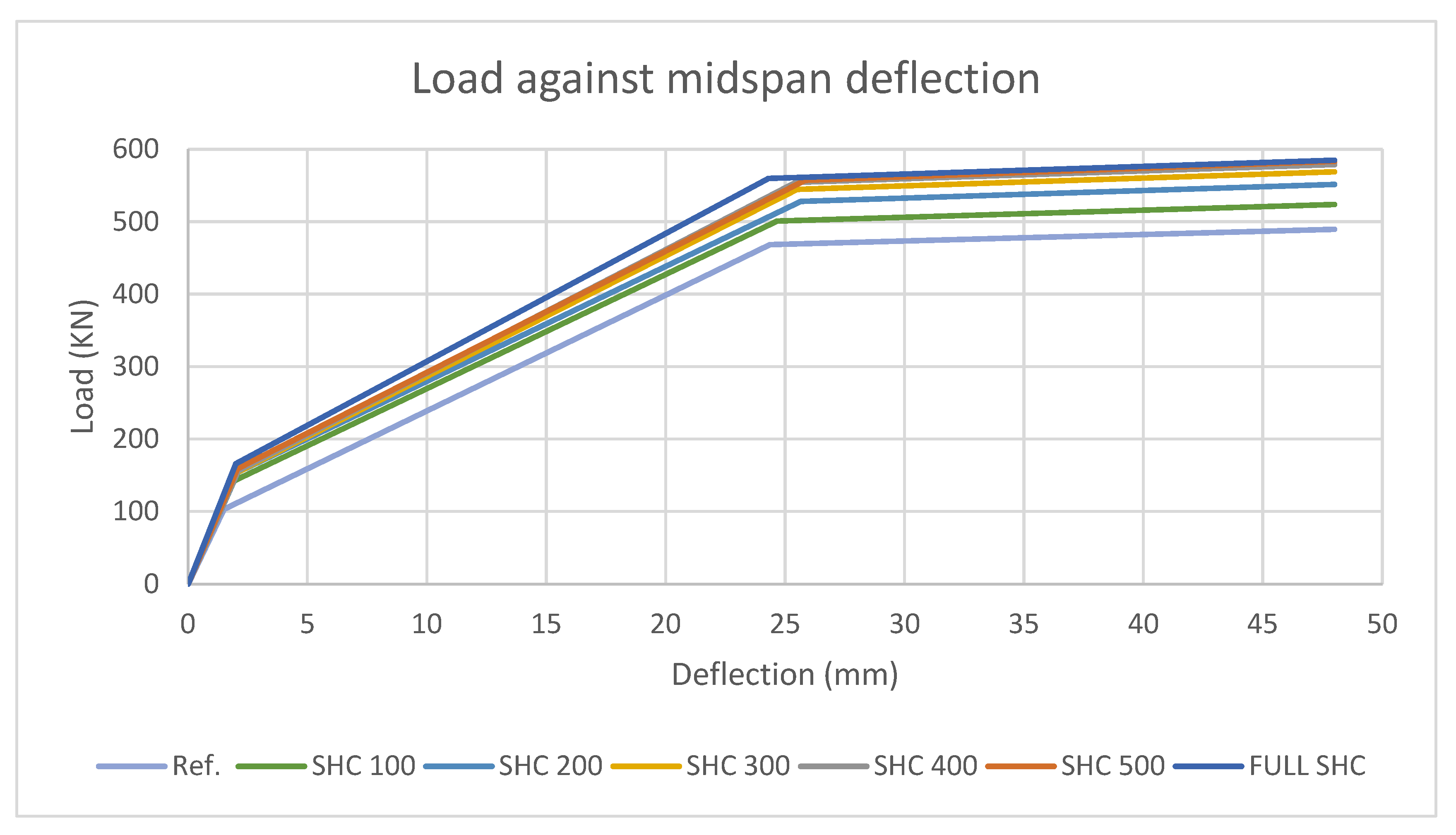
| Ref. | 1.505 | 103.081 | 24.362 | 468.285 | 48.000 | 489.387 |
| SHC100 | 1.902 | 141.949 | 24.667 | 500.776 | 48.000 | 523.600 |
| SHC200 | 2.087 | 154.240 | 25.654 | 527.928 | 48.000 | 551.278 |
| SHC300 | 2.070 | 154.399 | 25.504 | 544.401 | 48.000 | 568.725 |
| SHC400 | 2.086 | 155.897 | 25.448 | 554.187 | 48.000 | 578.893 |
| SHC500 | 2.067 | 159.036 | 25.842 | 557.020 | 48.000 | 583.322 |
| Full SHC | 2.000 | 166.109 | 24.308 | 559.441 | 48.000 | 584.741 |
| Increase in Overstrength (%) | Increase in Overstrength (%) | Increase in Overstrength (%) | ||||
| SHC100 | 32 | 7 | 7 | |||
| SHC200 | 40 | 13 | 12 | |||
| SHC300 | 40 | 12 | 15 | |||
| SHC400 | 41 | 17 | 17 | |||
| SHC500 | 43 | 17 | 18 | |||
| Full SHC | 47 | 18 | 18 | |||
Disclaimer/Publisher’s Note: The statements, opinions and data contained in all publications are solely those of the individual author(s) and contributor(s) and not of MDPI and/or the editor(s). MDPI and/or the editor(s) disclaim responsibility for any injury to people or property resulting from any ideas, methods, instructions or products referred to in the content. |
© 2023 by the authors. Licensee MDPI, Basel, Switzerland. This article is an open access article distributed under the terms and conditions of the Creative Commons Attribution (CC BY) license (https://creativecommons.org/licenses/by/4.0/).
Share and Cite
Alkhuzai, K.; Di Sarno, L.; Haredy, A.; Alahmadi, R.; Albuhairi, D. Numerical Simulation of the Performance of Self-Healing Concrete in Beam Elements. Buildings 2023, 13, 809. https://doi.org/10.3390/buildings13030809
Alkhuzai K, Di Sarno L, Haredy A, Alahmadi R, Albuhairi D. Numerical Simulation of the Performance of Self-Healing Concrete in Beam Elements. Buildings. 2023; 13(3):809. https://doi.org/10.3390/buildings13030809
Chicago/Turabian StyleAlkhuzai, Khalid, Luigi Di Sarno, Abdullah Haredy, Raed Alahmadi, and Danah Albuhairi. 2023. "Numerical Simulation of the Performance of Self-Healing Concrete in Beam Elements" Buildings 13, no. 3: 809. https://doi.org/10.3390/buildings13030809