

Investigation of Moisture Condensation on the Surface of the Bottom Chord of a Steel Truss of a Historical Building
 ,
,  ,
, 
Abstract
:1. Introduction
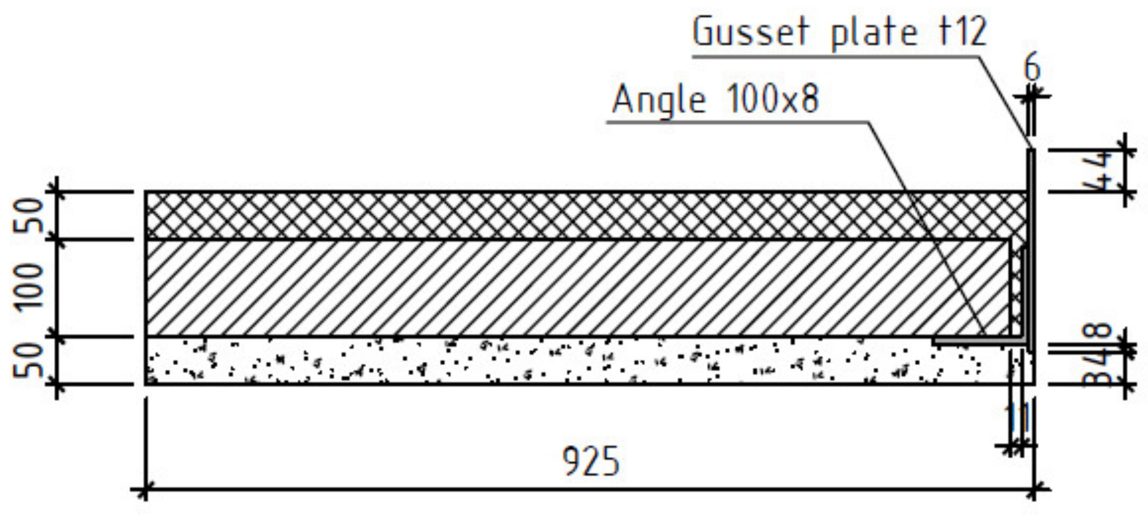
2. Materials and Methods
- -
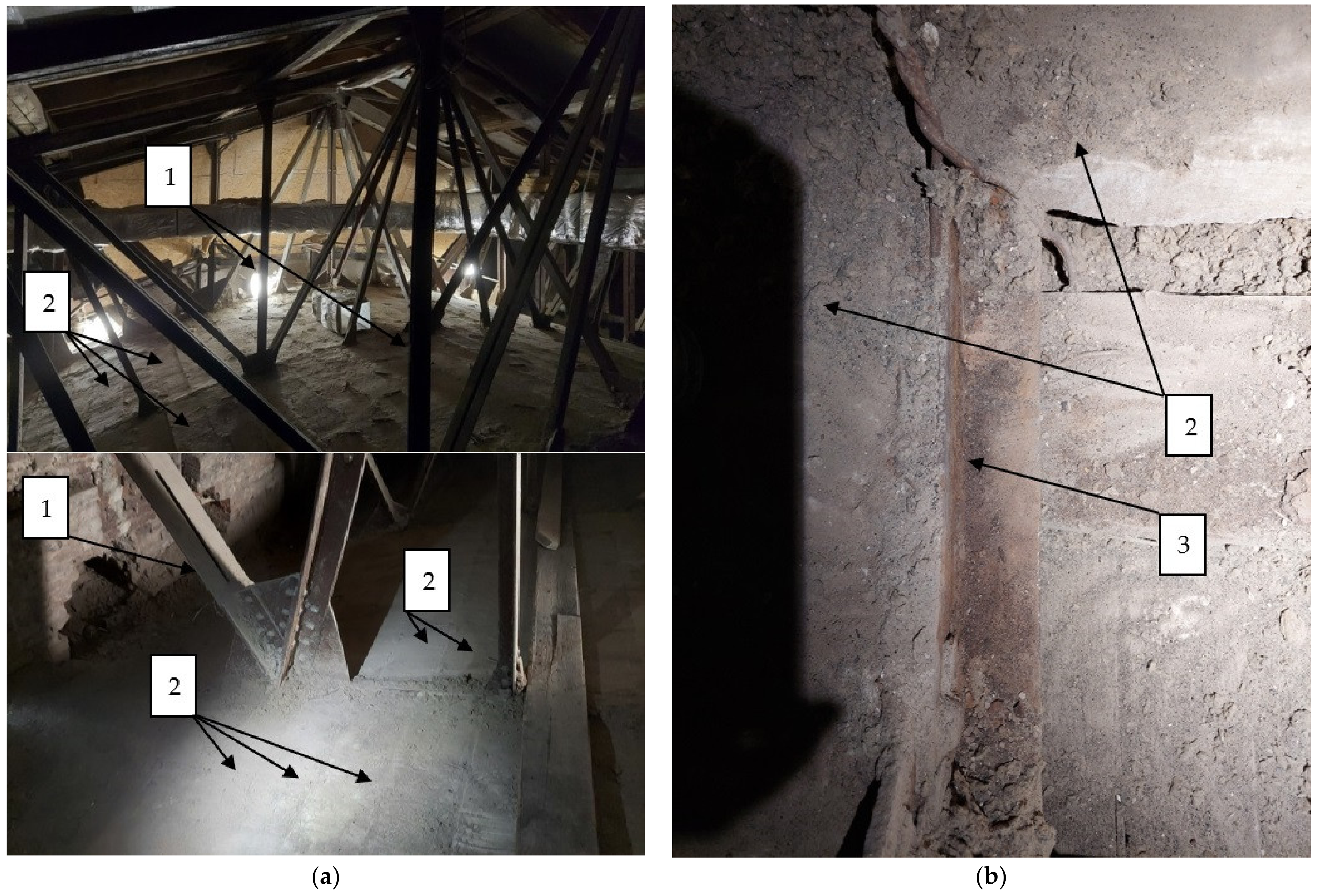
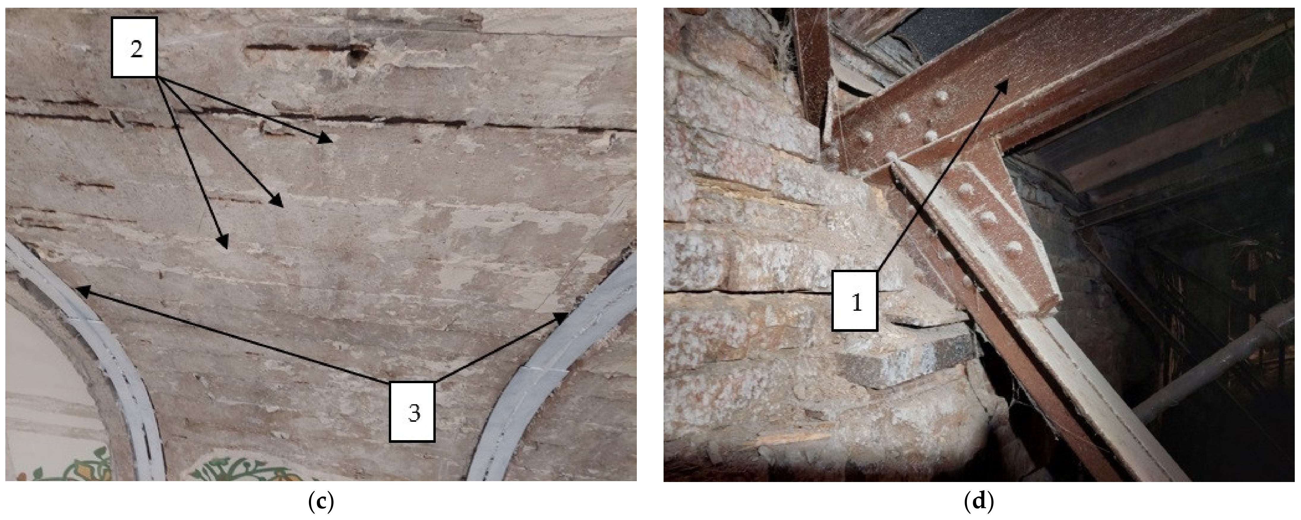
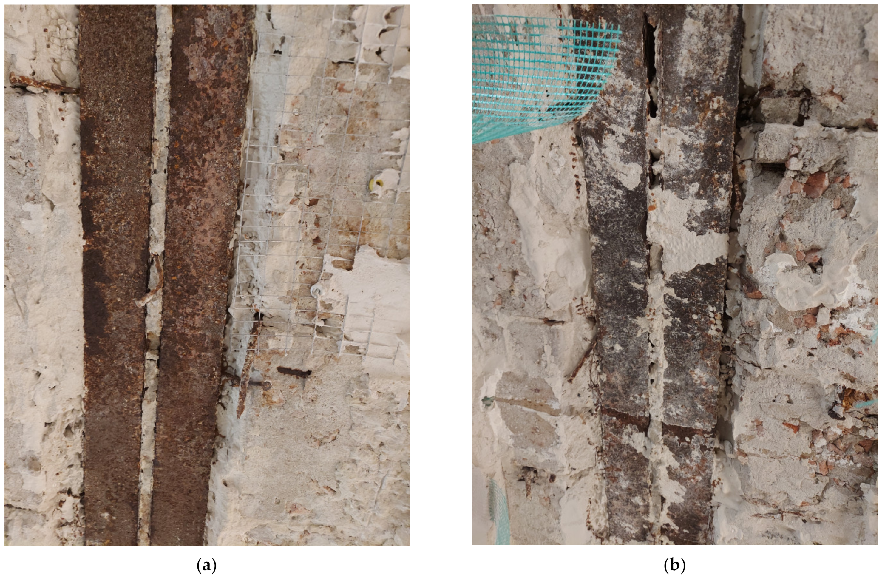
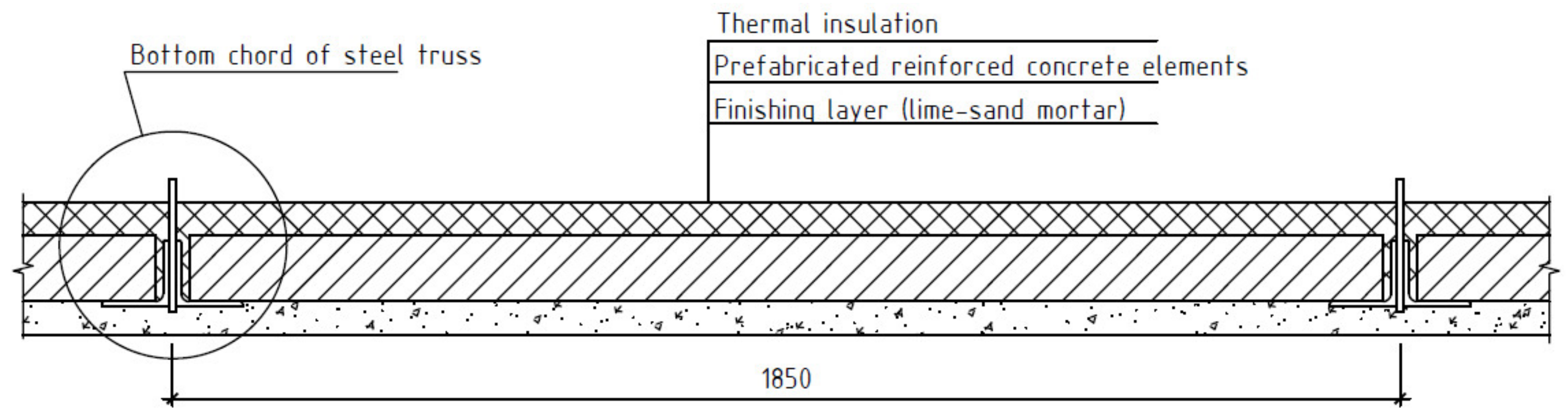
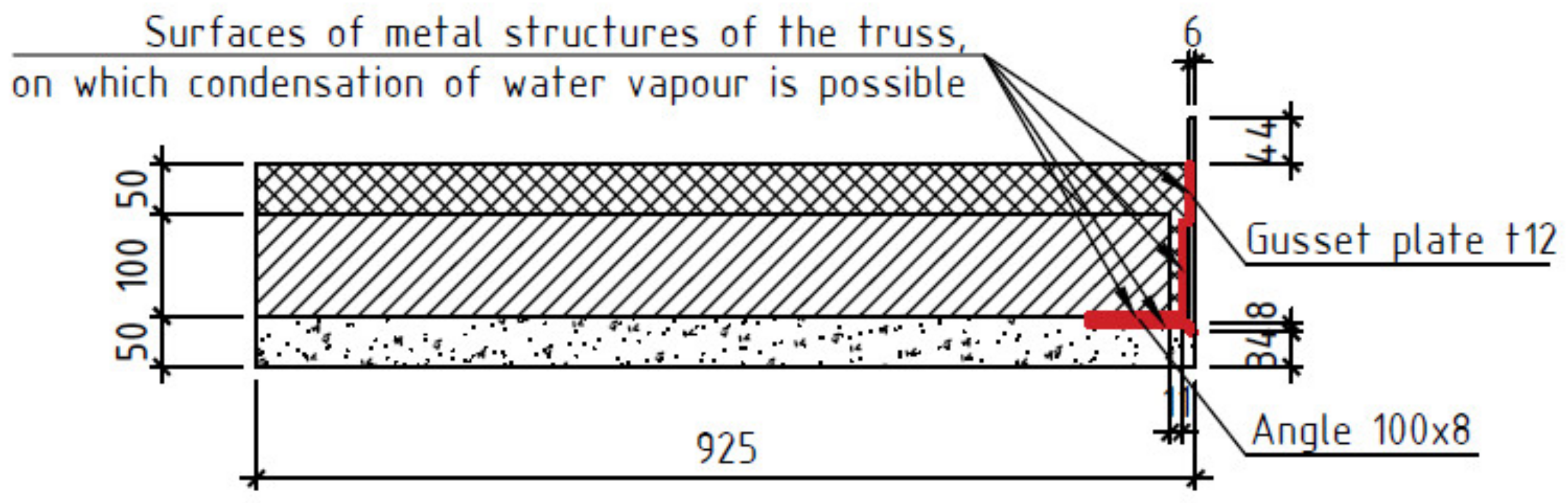
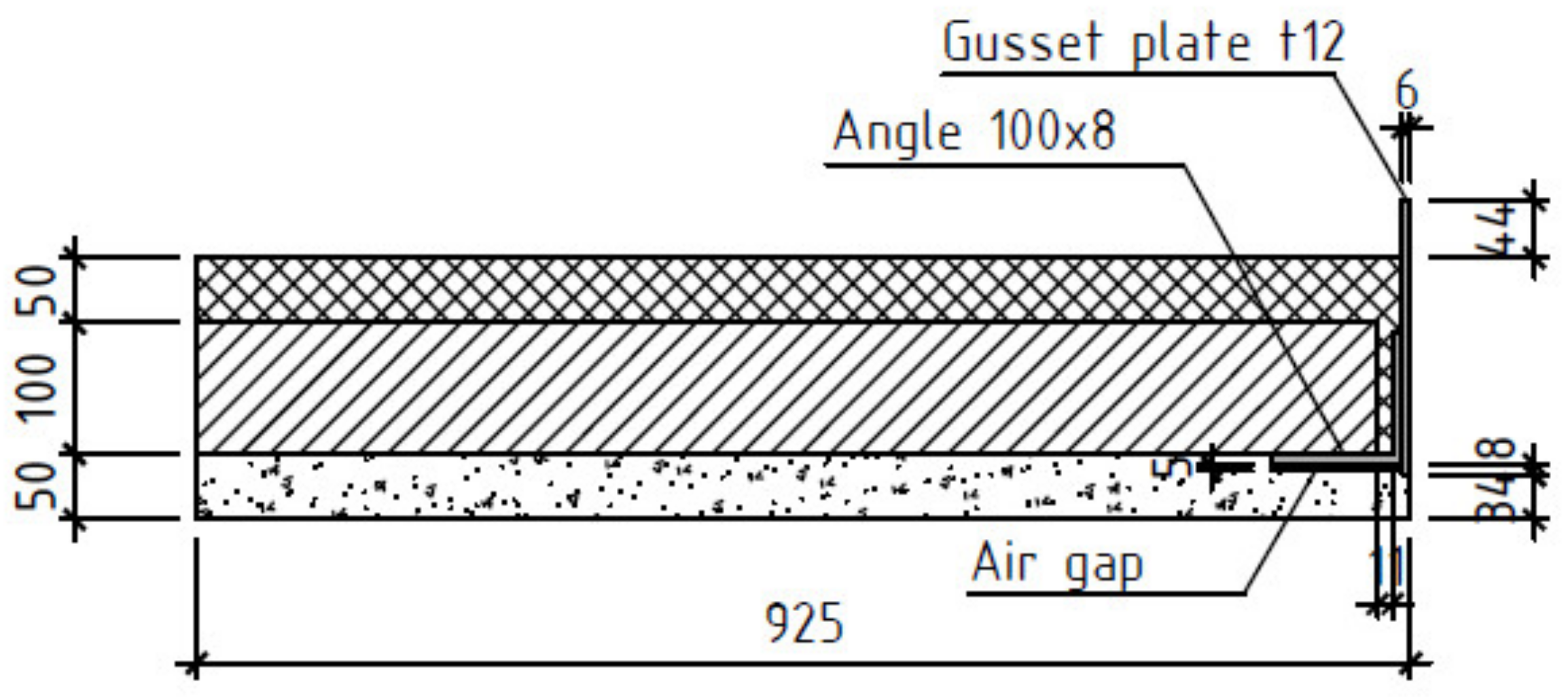
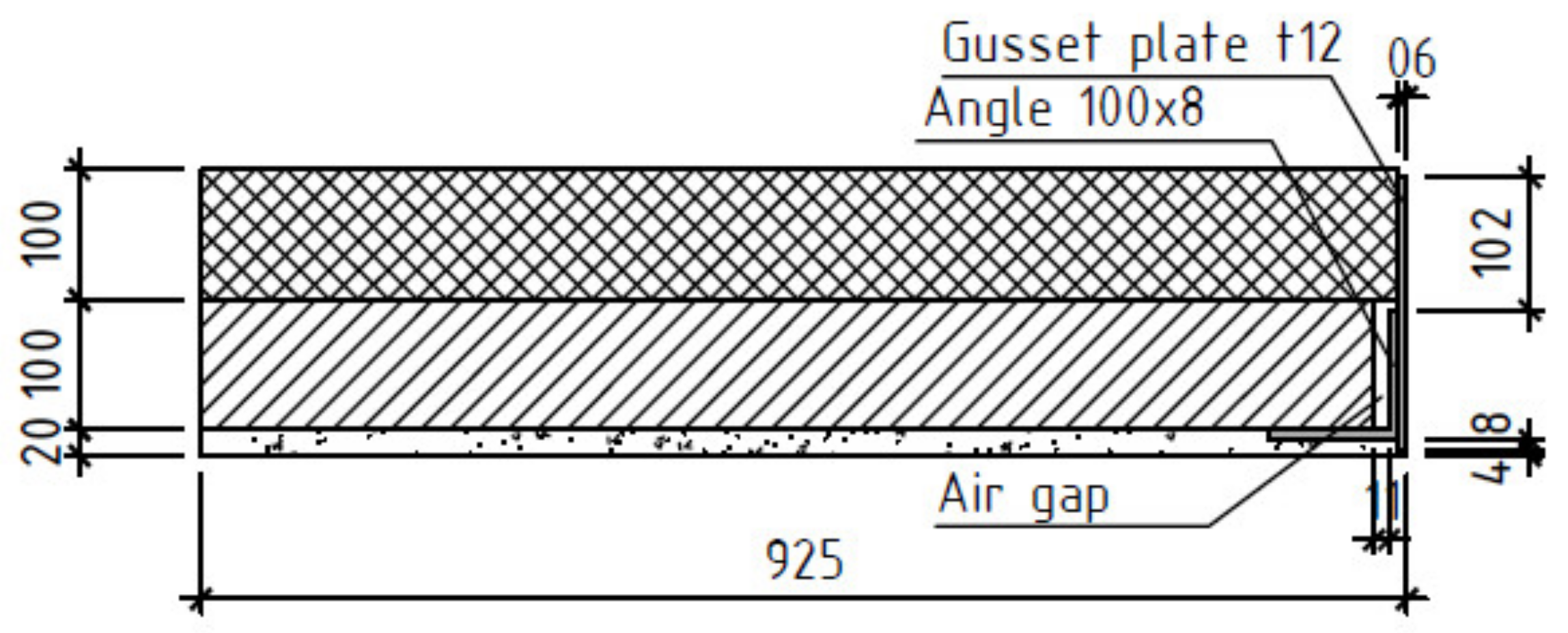
- The presence of thermal insulation (Figure 5b) was modelled with different options for filling the gap between the reinforced concrete element and the angles of the truss with thermal insulation for the area with a gusset plate connecting the two angles and for the area without a gusset plate.
- -
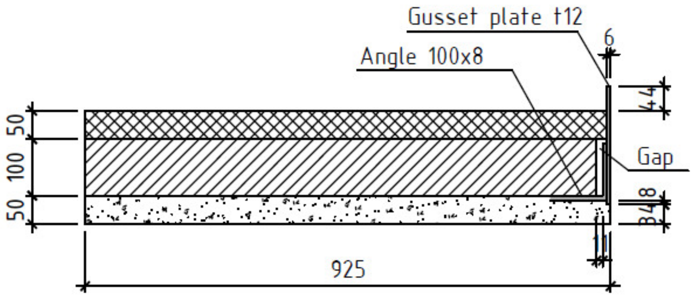
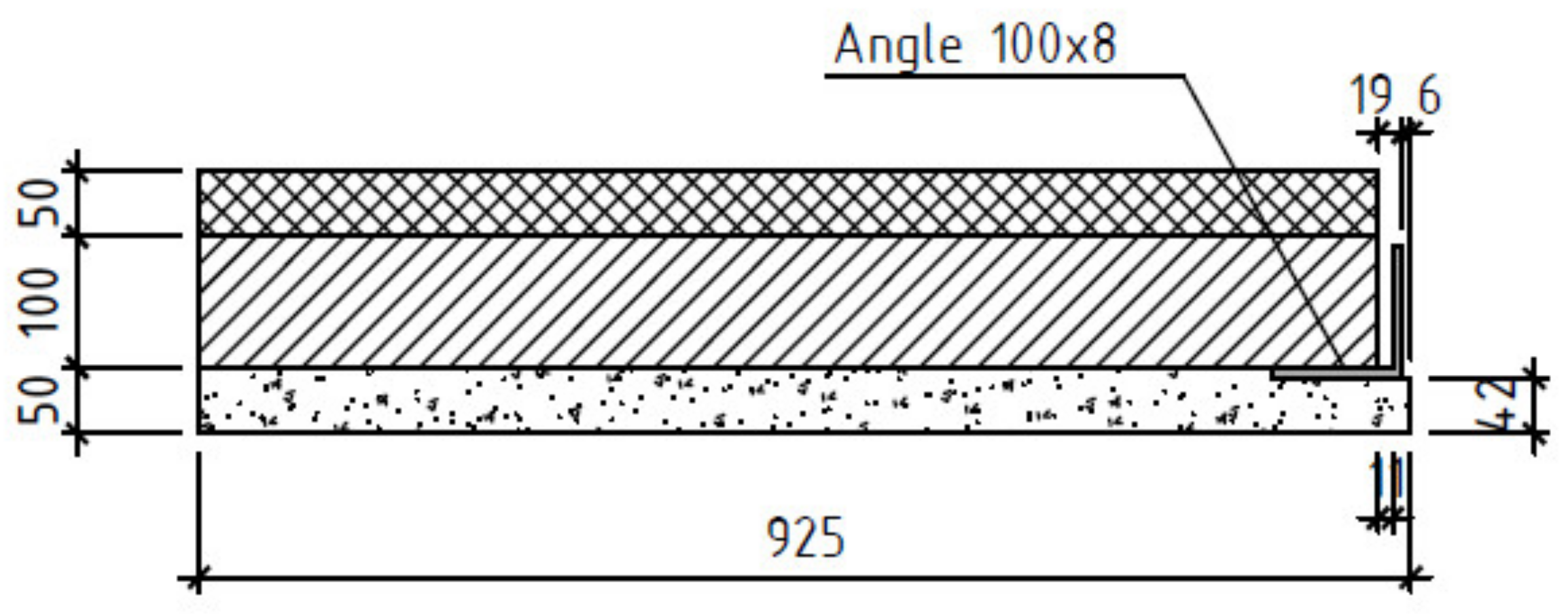
- The finishing layer detachment from angles of the truss (Figure 5a) was modelled in the form of a gap of various sizes.
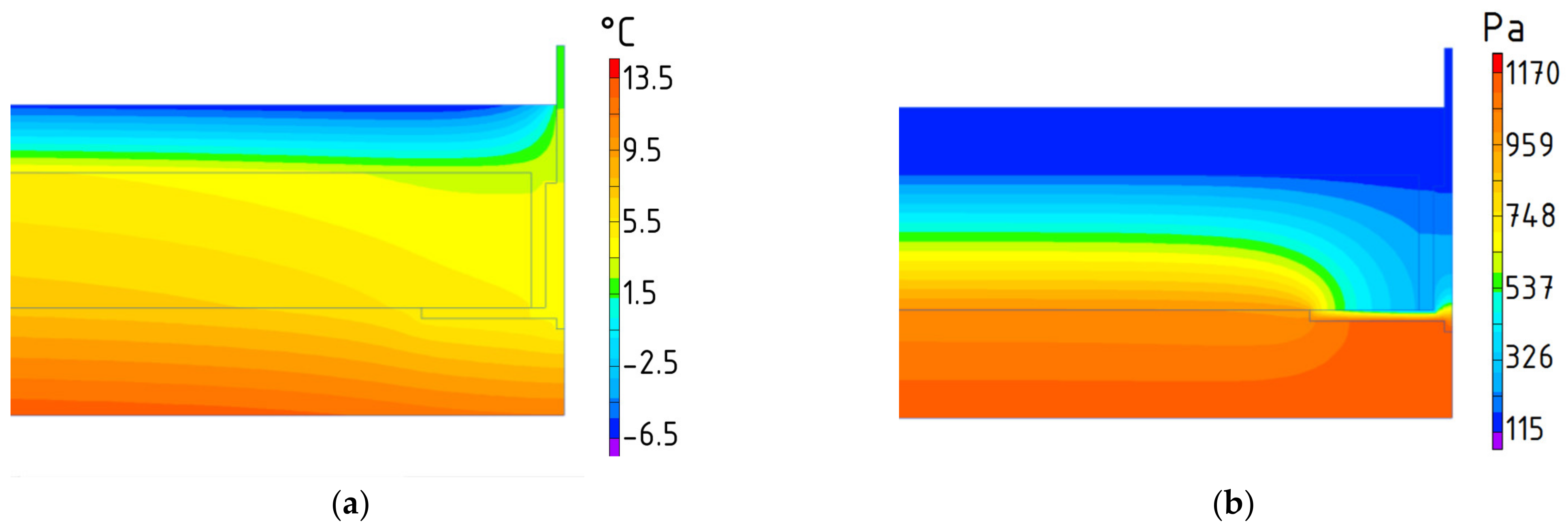
3. Results
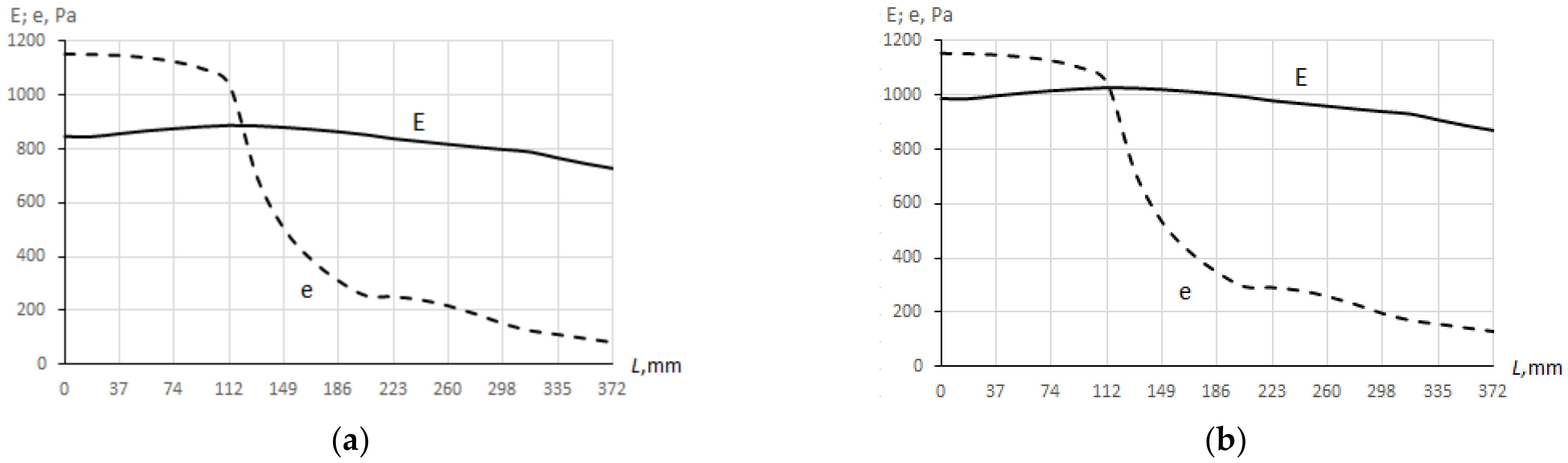
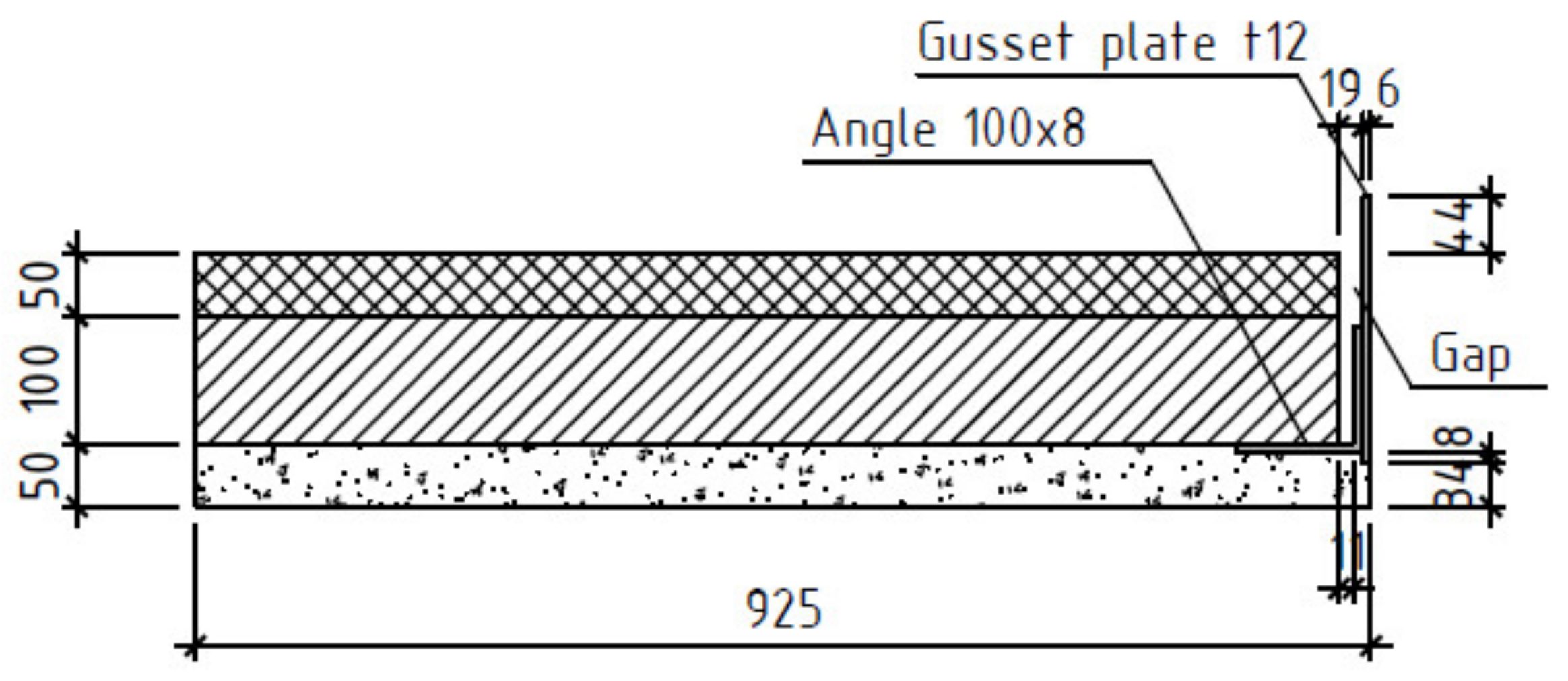
3.1. Calculation Scheme with a Gusset Plate: The Gaps between the Angles and Precast Reinforced Concrete Elements Are Not Filled with Thermal Insulation
3.2. Calculation Scheme with a Gusset Plate: Detachment of the Finishing Layer from the Elements of the Bottom Chord of the Truss
3.3. Calculation Scheme with a Gusset Plate: Partial Filling of the Gap with Thermal Insulation between Precast Concrete Elements and Metal Structures
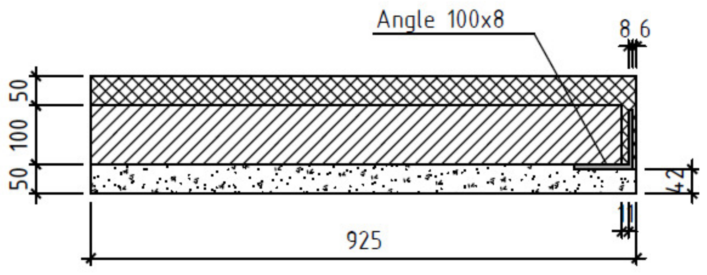
3.4. Calculation Scheme without a Gusset Plate: The Gaps between the Angles and Precast Reinforced Concrete Elements Are Filled with Thermal Insulation
3.5. Calculation Scheme without a Gusset Plate: The Gaps between the Angles and Precast Reinforced Concrete Elements Are Not Filled with Thermal Insulation
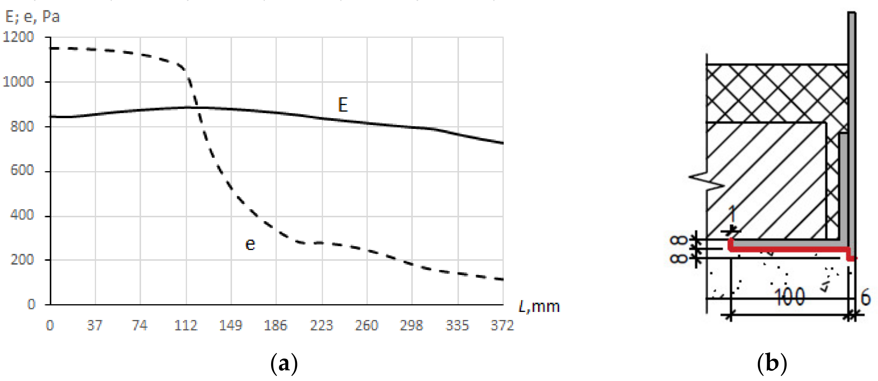
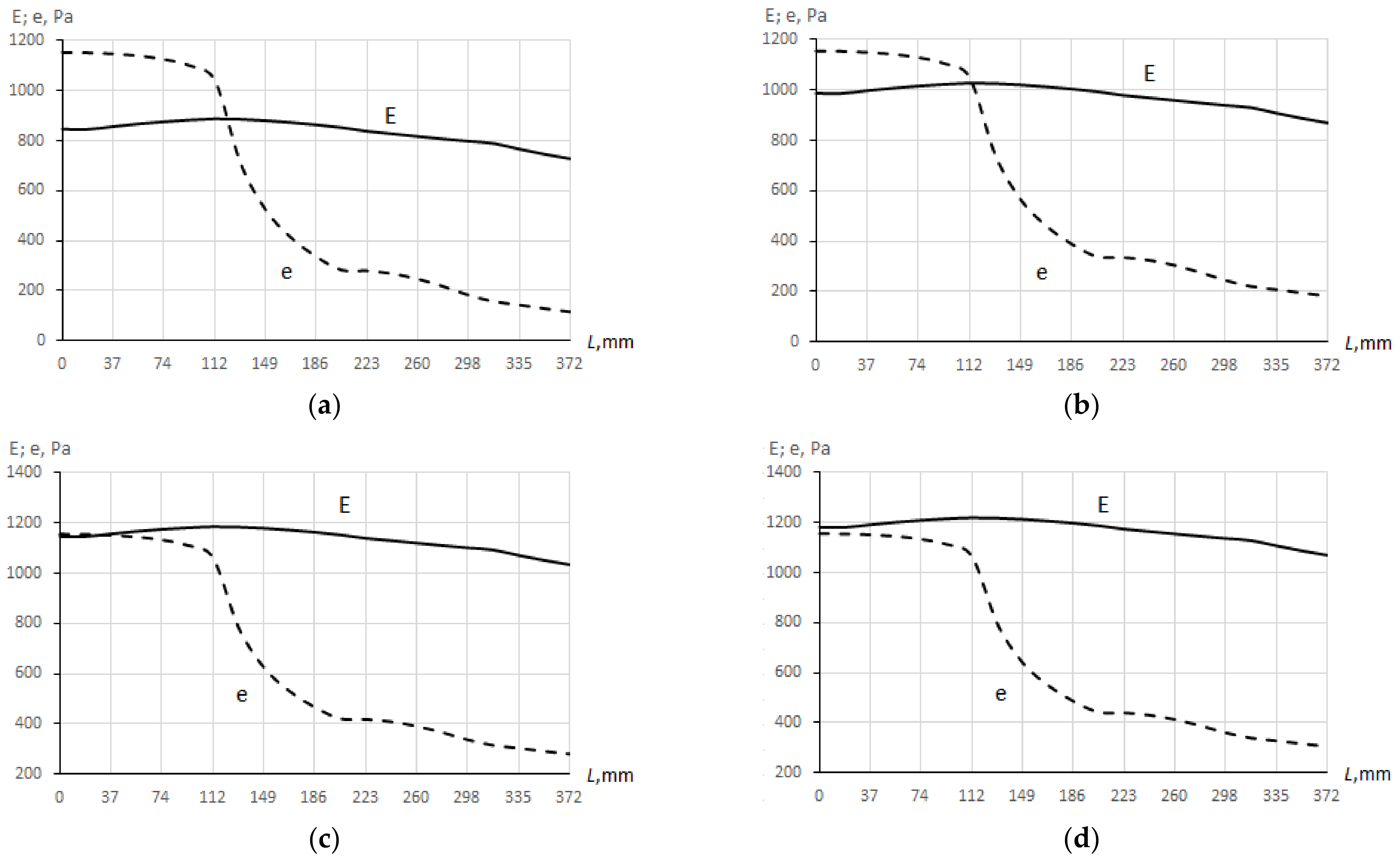
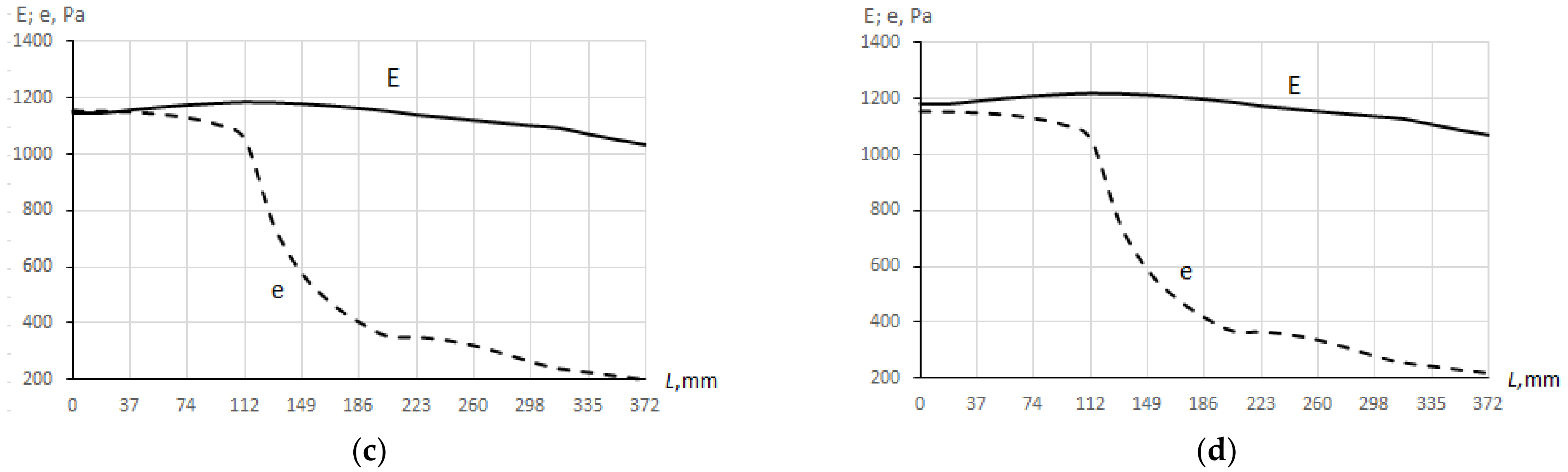
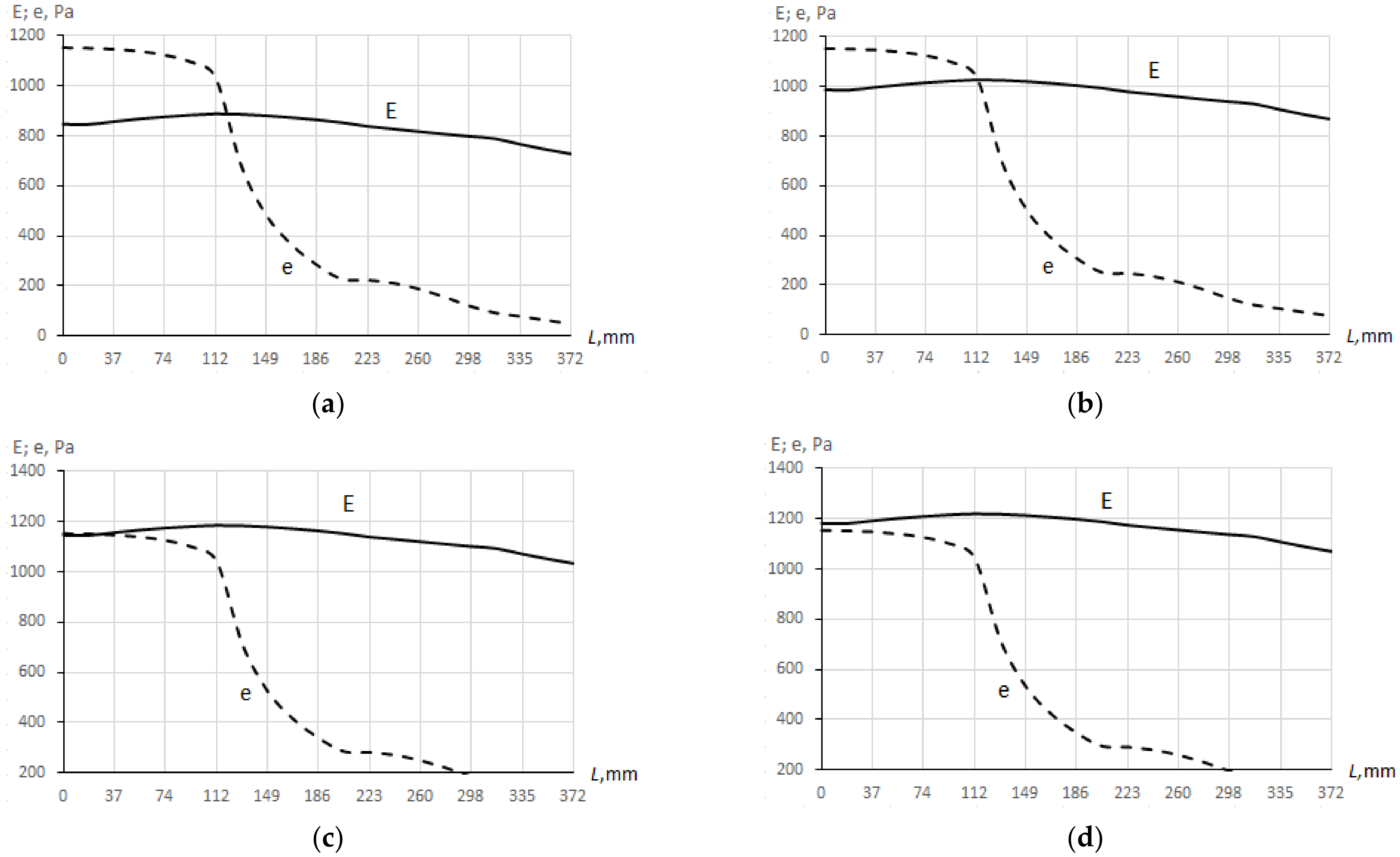
3.6. Verification Calculations of the Possibility of Condensate Formation on the Metal Surfaces of the Bottom Chord of Trusses
3.6.1. Calculation Scheme with a Gusset Plate: Thermal Insulation—Mineral Wool with a Density of and a Thickness of 100 mm
3.6.2. Calculation Scheme without a Gusset Plate: Thermal Insulation—Mineral Wool with a Density of and a Thickness of 100 mm
4. Discussion
5. Conclusions
Author Contributions
Funding
Data Availability Statement
Acknowledgments
Conflicts of Interest
References
- Heindl, W.; Krec, K.; Panzhauser, E.; Sigmund, A. Wärmebrücken; Springer: Wien, Austria, 1987. (In German) [Google Scholar]
- Panzhauser, E.; Rabenseifer, R. Die bauökologische Belastung der umgebenden Außenwelt durch sanierte und nichtsanierte Plattenwohnhäuser anhand eines Beispiels aus Bratislava. In Proceedings of the 1996 International Symposium of CIB Working Commission 67-Energy and Mass Flow in the Life Cycle of Buildings, Vienna, Austria, 4–10 August 1996; pp. 361–366. (In German). [Google Scholar]
- Skibitska, T.; Shuleshko, I. Decorative decoration of Poltava buildings in the 1900–1910s. Res. Fine Arts 2016, 2, 65–72. (In Ukrainian) [Google Scholar]
- Pavlovsky, V. The Live and Work of Vasyl H. Krychevsky; The Ukrainian Academy of Arts and Sciences in the U.S., Inc.: New York, NY, USA, 1974. (In Ukrainian) [Google Scholar]
- Chepelyk, V. Ukrainian Architectural Modern; KNUBA: Kyiv, Ukraine, 2000. (In Ukrainian) [Google Scholar]
- Semko, O.; Filonenko, O.; Hasenko, L.; Mahas, N.; Rudenko, V. Temperature-humidity regime in the operation of the roofs of historic buildings. Acad. J. Ind. Mach. Build. Civ. Eng. 2021, 2, 47–52. [Google Scholar]
- Soufeiani, L.; Foliente, G.; Nguyen, K.; San Nicolas, R. Corrosion protection of steel elements in façade systems—A review. J. Build. Eng. 2020, 32, 101759. [Google Scholar] [CrossRef]
- Martín-Garín, A.; Millán-García, J.A.; Terés-Zubiaga, J.; Oregi, X.; Rodríguez-Vidal, I.; Baïri, A. Improving Energy Performance of Historic Buildings through Hygrothermal Assessment of the Envelope. Buildings 2021, 11, 410. [Google Scholar] [CrossRef]
- Graham, L.; Scott, M.; Pappas, A. Natatorium Building Enclosure Deterioration Due to Moisture Migration. Buildings 2012, 2, 534–541. [Google Scholar] [CrossRef] [Green Version]
- You, S.; Li, W.; Ye, T.; Hu, F.; Zheng, W. Study on moisture condensation on the interior surface of buildings in high humidity climate. Build. Environ. 2017, 125, 39–48. [Google Scholar] [CrossRef]
- Nguyen, C.K.; Teodosiu, C.; Kuznik, F.; David, D.; Teodosiu, R.; Rusaouën, G. A full-scale experimental study concerning the moisture condensation on building glazing surface. Build. Environ. 2019, 156, 215–224. [Google Scholar] [CrossRef] [Green Version]
- Nguyen, C.K.; Teodosiu, C.; Kuznik, F.; David, D.; Rusaouën, G. Full-scale experimental study of moisture condensation on the glazing surface: Condensation rate characterization. IOP Conf. Ser. Mater. Sci. Eng. 2019, 609, 032035. [Google Scholar] [CrossRef]
- Hong, G.; Kim, D.D.; Kim, B.S. Experimental Investigation of Thermal Behaviors in Window Systems by Monitoring of Surface Condensation Using Full-Scale Measurements and Simulation Tools. Energies 2016, 9, 979. [Google Scholar] [CrossRef] [Green Version]
- Nawalany, G.; Sokołowski, P.; Michalik, M. Experimental Study of Thermal and Humidity Conditions in a Historic Wooden Building in Southern Poland. Buildings 2020, 10, 118. [Google Scholar] [CrossRef]
- Yurin, O.; Mahas, N.; Zyhun, A.; Musiienko, O. Aspects of calculation of resistance vapor penetration of enclosing structures. Acad. J. Ind. Mach. Build. Civ. Eng. 2020, 2, 96–101. [Google Scholar]
- Yurin, O.; Mammadov, N.; Semko, P.; Mahas, N. Analysis of the Humidity Condition of Wall Enclosing Structures of Cooling Warehouses and Possible Ways to Improve It. Lect. Notes Civ. Eng. 2022, 181, 439–448. [Google Scholar] [CrossRef]
- Colinart, T.; Glouannec, P.; Pierre, T.; Chauvelon, P.; Magueresse, A. Experimental Study on the Hygrothermal Behavior of a Coated Sprayed Hemp Concrete Wall. Buildings 2013, 3, 79–99. [Google Scholar] [CrossRef] [Green Version]
- Biserni, C.; Imbiombato, A.N. Numerical analysis on building envelope moisture condensation: A case study using the glaser diagram method. AIP Conf. Proc. 2019, 2191, 020023. [Google Scholar] [CrossRef]
- Kon, O.; Caner, İ. The Effect of External Wall Insulation on Mold and Moisture on the Buildings. Buildings 2022, 12, 521. [Google Scholar] [CrossRef]
- Ingebretsen, S.B.; Andenæs, E.; Gullbrekken, L.; Kvande, T. Microclimate and Mould Growth Potential of Air Cavities in Ventilated Wooden Façade and Roof Systems—Case Studies from Norway. Buildings 2022, 12, 1739. [Google Scholar] [CrossRef]
- Ksit, B.; Szymczak-Graczyk, A.; Pilch, R. Numerical Simulation of the Impact of Water Vapour and Moisture Blockers in Energy Diagnostics of Ventilated Partitions. Materials 2022, 15, 8257. [Google Scholar] [CrossRef]
- Korenkova, R.; Krusinsky, P.; Pisca, P. Analysis of the Impact of Microclimate in a Roof Space on a Gothic Truss. Constr. Commun. Sci. Lett. Univ. Zilina 2013, 15, 27–31. [Google Scholar] [CrossRef]
- Kysela, P.; Ponechal, R.; Krušinský, P.; Korenková, R. Pilot monitoring of the internal temperature and humidity in the historic building attic space. Transp. Res. Procedia 2021, 55, 1214–1220. [Google Scholar] [CrossRef]
- Spišáková, M.; Mokrenko, D. Renovation of roof structure of historical building–case study. Czech J. Civ. Eng. 2021, 6, 71–78. [Google Scholar] [CrossRef]
- Semko, O.V.; Yurin, O.I.; Filonenko, O.I.; Mahas, N.M. Investigation of the Temperature–Humidity State of a Tent-Covered Attic. Lect. Notes Civ. Eng. 2020, 73, 245–252. [Google Scholar] [CrossRef]
- Richter, J.; Staněk, K.; Tywoniak, J.; Kopecký, P. Moisture-Safe Cold Attics in Humid Climates of Europe and North America. Energies 2020, 13, 3856. [Google Scholar] [CrossRef]
- Kvist Hansen, T. Danish Dwellings with Cold Attics—Ventilation Rates and Air Exchange between Attic and Dwelling. Buildings 2021, 11, 64. [Google Scholar] [CrossRef]
- Rupp, S.H.; McNeil, S.; Plagmann, M.; Overton, G. Hygrothermal Characteristics of Cold Roof Cavities in New Zealand. Buildings 2021, 11, 334. [Google Scholar] [CrossRef]
- Gullbrekken, L.; Kvande, T.; Jelle, B.P.; Time, B. Norwegian Pitched Roof Defects. Buildings 2016, 6, 24. [Google Scholar] [CrossRef] [Green Version]
- Lisitano, I.M.; Laggiard, D.; Fantucci, S.; Serra, V.; Fenoglio, E. Evaluating the Impact of Indoor Insulation on Historic Buildings: A Multilevel Approach Involving Heat and Moisture Simulations. Appl. Sci. 2021, 11, 7944. [Google Scholar] [CrossRef]
- Negro, E.; Cardinale, T.; Cardinale, N.; Rospi, G. Italian Guidelines for Energy Performance of Cultural Heritage and Historical Buildings: The Case Study of the Sassi of Matera. Energy Procedia 2016, 97, 7–14. [Google Scholar] [CrossRef] [Green Version]
- Curto, D.; Franzitta, V.; Guercio, A.; Panno, D. Energy Retrofit. A Case Study—Santi Romano Dormitory on the Palermo University. Sustainability 2021, 13, 13524. [Google Scholar] [CrossRef]
- Harrestrup, M.; Svendsen, S. Full-scale test of an old heritage multi-storey building undergoing energy retrofitting with focus on internal insulation and moisture. Build. Environ. 2015, 85, 123–133. [Google Scholar] [CrossRef]
- Todorović, M.S.; Ećim-Đurić, O.; Nikolić, S.; Ristić, S.; Polić-Radovanović, S. Historic building’s holistic and sustainable deep energy refurbishment via BPS, energy efficiency and renewable energy—A case study. Energy Build. 2015, 95, 130–137. [Google Scholar] [CrossRef]
- Ameen, A.; Bahrami, A.; El Tayara, K. Energy Performance Evaluation of Historical Building. Buildings 2022, 12, 1667. [Google Scholar] [CrossRef]
- Webb, A.L. Energy retrofits in historic and traditional buildings: A review of problems and methods. Renew. Sustain. Energy Rev. 2017, 77, 748–759. [Google Scholar] [CrossRef]
- Mazzarella, L. Energy retrofit of historic and existing buildings. The legislative and regulatory point of view. Energy Build. 2015, 95, 23–31. [Google Scholar] [CrossRef]
- DSTU ISO 10211-1:2005; Thermal Bridges in Building Construction—Calculation of Heat Flows and Surface Temperatures—Part 1: General Methods (ISO 10211-1:1995, IDT). Derzhspozhyvstandart of Ukraine: Kyiv, Ukraine, 2008; Valid in Ukraine from 2008 to present.
- DBN V.2.6-31: 2021; Thermal Insulation and Energy Efficiency of Buildings. Minregion of Ukraine: Kyiv, Ukraine, 2022; Valid in Ukraine from 2022 to present.
- DSTU-N B V.2.6-189: 2013; Methods for Choosing Heat-Insulating Material for Building Insulation. Minregion of Ukraine: Kyiv, Ukraine, 2014; Valid in Ukraine from 2014 to present.


| Name of the Layer | Thickness, m | Thermal Conductivity, W/(m∙K) | Vapor Permeability Coefficient, mg/(m∙h∙Pa) |
|---|---|---|---|
| Finishing layer (lime-sand mortar) | 0.05 | 0.81 | 0.12 |
| Precast reinforced concrete elements | 0.1 | 2.04 | 0.03 |
| Thermal insulation contaminated with debris | 0.05 | 0.26 | 0.22 |
| Metal | 58 | 0 |
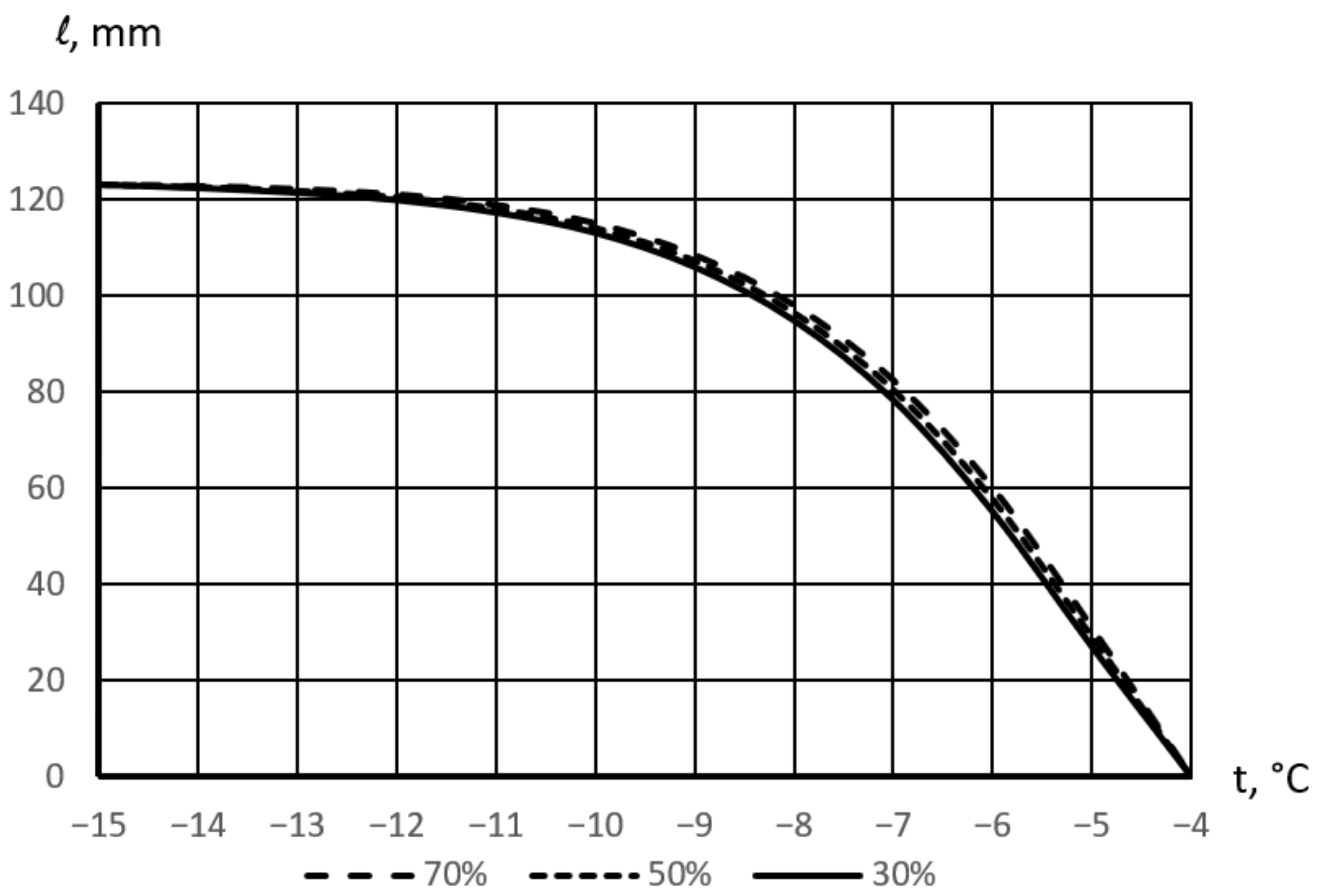
| Air Temperature in the Attic, °C | The Length of the Condensation Area along the Perimeter of the Section of the Bottom Chord of the Truss, mm at Relative Air Humidity in the Attic, % | ||
|---|---|---|---|
| 70 | 50 | 30 | |
| −15 | 123 | 123 | 123 |
| −10 | 115 | 114 | 113 |
| −5 | 31 | 29 | 27 |
| −4 | 0 | 0 | 0 |
| Air Temperature in the Attic, °C | The Length of the Condensation Area along the Perimeter of the Section of the Bottom Chord of the Truss, mm at Relative Air Humidity in the Attic 70% |
|---|---|
| −15 | 143 |
| −10 | 133 |
| −5 | 126 |
| 0 | 116 |
| 4 | 0 |
| Air Temperature in the Attic, °C | The Length of the Condensation Area along the Perimeter of the Section of the Bottom Chord of the Truss, mm at Relative Air Humidity in the Attic 70% At Air Gap Sizes, mm | ||
|---|---|---|---|
| 5 | 10 | 15 | |
| −15 | 125 | 126 | 126 |
| −10 | 121 | 122 | 123 |
| −5 | 76 | 90 | 99 |
| −3 | 0 | 0 | 0 |
| Air Temperature in the Attic, °C | the Length of the Condensation Area along the Perimeter of the Section of the Bottom Chord of the Truss, mm at Relative Air Humidity in the Attic 70% |
|---|---|
| −15 | 123 |
| −10 | 114 |
| −5 | 31 |
| −4 | 0 |
| Air Temperature in the Attic, °C | The Length of the Condensation Area along the Perimeter of the Section of the Bottom Chord of the Truss, mm at Relative Air Humidity in the Attic 70% |
|---|---|
| −15 | 60 |
| −14 | 0 |
| Air Temperature in the Attic, °C | The Length of the Condensation Area along the Perimeter of the Section of the Bottom Chord of the Truss, mm at Relative Air Humidity in the Attic 70% |
|---|---|
| −15 | 122 |
| −10 | 108 |
| −5 | 93 |
| 0 | 45 |
| 1 | 0 |
Disclaimer/Publisher’s Note: The statements, opinions and data contained in all publications are solely those of the individual author(s) and contributor(s) and not of MDPI and/or the editor(s). MDPI and/or the editor(s) disclaim responsibility for any injury to people or property resulting from any ideas, methods, instructions or products referred to in the content. |
© 2023 by the authors. Licensee MDPI, Basel, Switzerland. This article is an open access article distributed under the terms and conditions of the Creative Commons Attribution (CC BY) license (https://creativecommons.org/licenses/by/4.0/).
Share and Cite
Semko, O.; Yurin, O.; Filonenko, O.; Semko, V.; Rabenseifer, R.; Mahas, N. Investigation of Moisture Condensation on the Surface of the Bottom Chord of a Steel Truss of a Historical Building. Buildings 2023, 13, 766. https://doi.org/10.3390/buildings13030766
Semko O, Yurin O, Filonenko O, Semko V, Rabenseifer R, Mahas N. Investigation of Moisture Condensation on the Surface of the Bottom Chord of a Steel Truss of a Historical Building. Buildings. 2023; 13(3):766. https://doi.org/10.3390/buildings13030766
Chicago/Turabian StyleSemko, Oleksandr, Oleg Yurin, Olena Filonenko, Volodymyr Semko, Roman Rabenseifer, and Nataliia Mahas. 2023. "Investigation of Moisture Condensation on the Surface of the Bottom Chord of a Steel Truss of a Historical Building" Buildings 13, no. 3: 766. https://doi.org/10.3390/buildings13030766