1. Introduction
The presented research concerns the activity of knowledge for the enhancement and maintenance of a symbolic place in the land of Lombardy, in Northern Italy: one of the fifty stations of the path of St. Augustine.
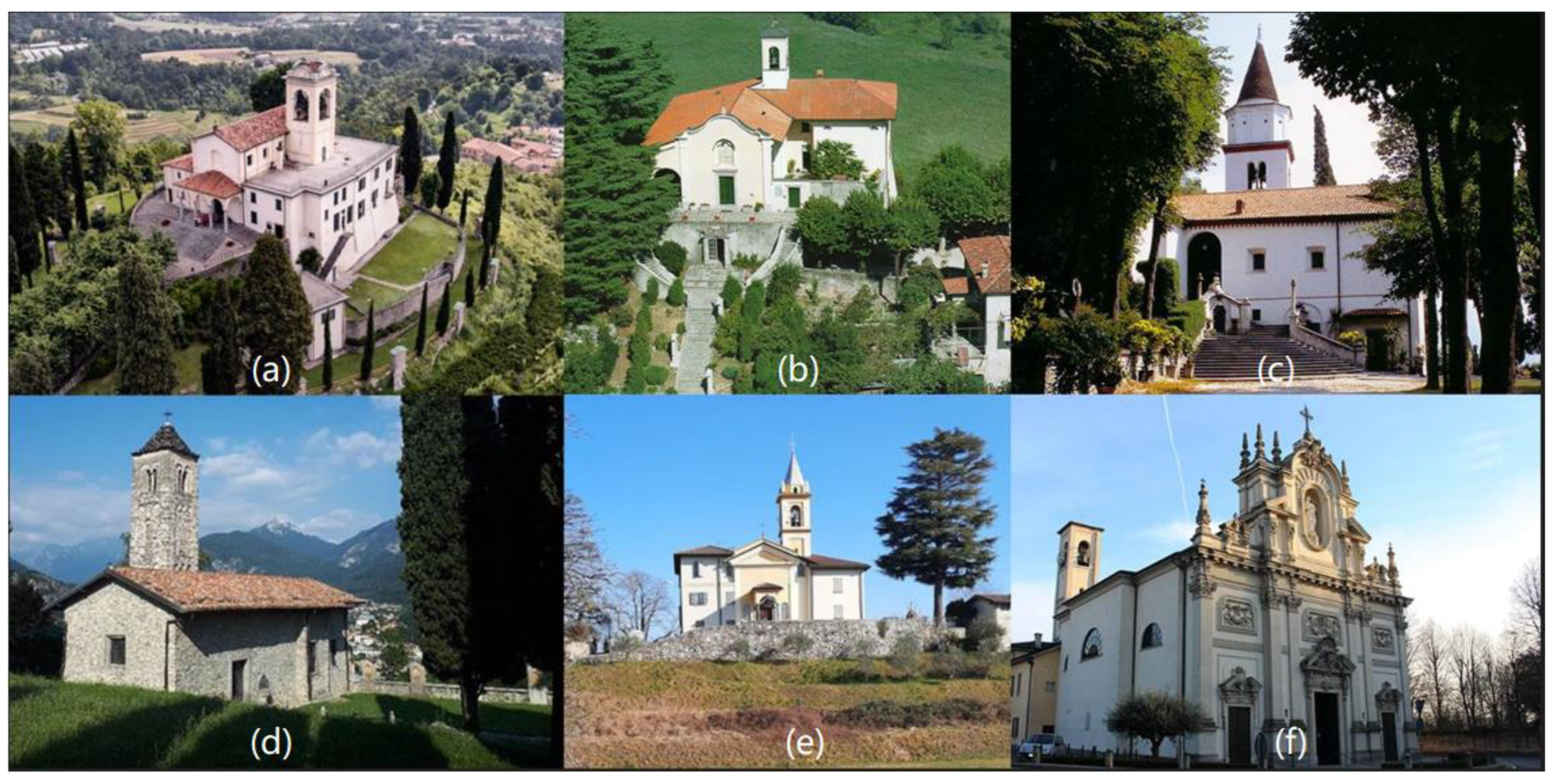
Figure 1 illustrates six example stations. The operation itself should be seen in the broader picture of the Cultural Routes as outlined by the Council of Europe. In 1987, the Council of Europe launched the “Cultural Routes” project [
1], bringing to the public’s attention the fact that through a journey through space and time, the cultural heritage (later named CH) of different countries and cultures of Europe can contribute to sharing the values of the identities and cultures of European communities. The whole program is set to become a medium for dialogue between European cultures and promote better knowledge and understanding of European cultural identity while preserving and enhancing natural heritage and CH. In 2013, the Enlarged Partial Agreement on Cultural Routes of the Council of Europe (EPA) [
2] was established to strengthen the program politically and financially. The EPA, based on the criteria established by the Committee of Ministers Resolution CM/Res (2013) 67, issues the “Cultural Route of the Council of Europe” certification by regularly evaluating Cultural Routes proposals. The principles required for certification are: involve a theme that is representative of European values and common to at least three countries in Europe; be the subject of transnational, multidisciplinary scientific research; enhance European memory, history, and heritage and contribute to the interpretation of Europe’s present-day diversity; support cultural and educational exchanges for young people; develop exemplary and innovative projects in the field of cultural tourism and sustainable cultural development; and develop tourist products and services aimed at different groups. Among the points under evaluation for the issuance of a certificate certifying Cultural Routes status, an entire chapter deals with “Enhancement of the memory, history and European heritage” [
3] and poses persuasive questions about the actual effectiveness of the walk as a Cultural Route. Among the questions asked, “Do the Route activities contribute to a better understanding of the concept of CH, the importance of its preservation and sustainable development?” seems to be the most suitable to be partially answered by our research here presented in its first phase.
In this scenario, we are interested in framing the Italian legislative set of rules within the CH Code. In Italy, the Legislative Decree of 22 January 2004 n 42, the “Code of cultural heritage and Landscape” according to article 10 of law 06 July 2022 [
4], explains with a series of definitions the scope within which the actions of our work move; the explanations on the protection actions are concentrated in the fourth article, that is the definition of protection of CH.
In the following articulation, the code develops themes of responsibility in charge of property ownership and conservation interventions, ensured through study, prevention, maintenance, and restoration activities. It also defines situations of prevention, i.e., the set of activities suitable for limiting risk situations related to the property in its context; maintenance, i.e., the set of activities and interventions intended to control the condition of the cultural property and maintain the integrity, efficiency, and identity of the property; and restoration, i.e., the direct intervention on the property through a set of operations aimed at the recovery of the property itself. The case study here discussed is therefore placed within these two scenarios: on the one hand, the choices of the EU in the field of launching and preserving Culture Routes, and on the other hand, the scenario of maintaining the assets and CH codified by the Italian regulations.
In this scenario, the economic power that CH can generate with tourist flows should be considered. Even in the AEC (architecture, engineering, and construction) sector, the volume of assets that require renovation and maintenance far exceeds that of new construction, which constitutes a potential basin for economically relevant interventions. However, even though applied research in the digital CH field is constantly growing [
5,
6,
7], the opportunities and direct spillovers in the construction sector and the transmission of values within communities are not yet codified. The contribution of CH to economic growth and social cohesion is underestimated despite all the efforts of the European community in funding projects that aspire to raise more awareness of the impact of CH on social, economic, cultural, and community development [
8,
9,
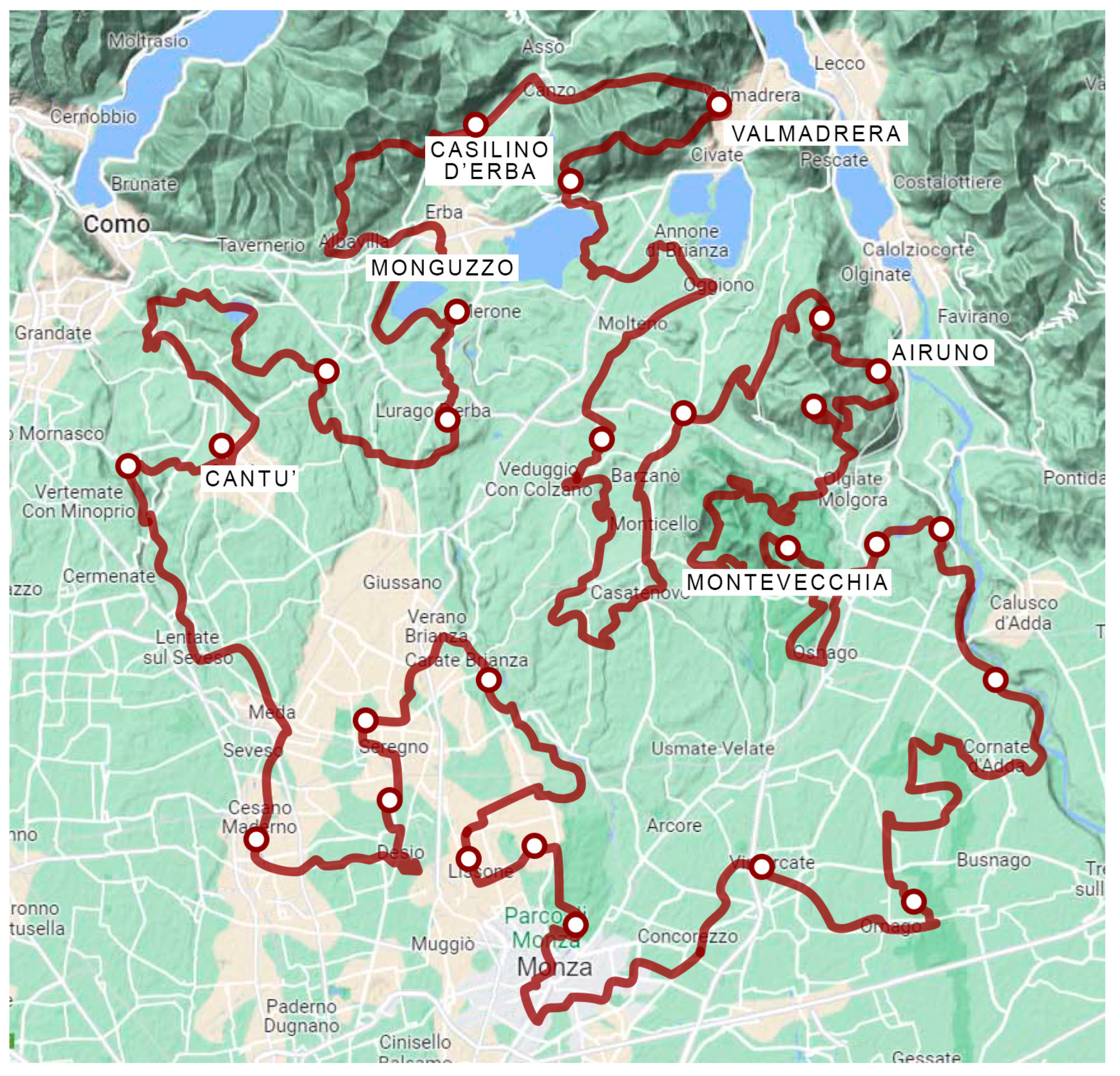
10]. The enhancement of CH does trigger positive spillovers, but they are difficult to quantify when we are talking about the digitization of a material asset, regardless of the purposes of its use; this is even more so if we are talking about an entire territory, for example, a map of the St. Augustine Route is shown in
Figure 2. The Way of St. Augustine [
11,
12,
13,
14] is a path in which a series of stages are presented, in particular, the Monastery of Airuno and the hill that hosts it. The walk through the stages of the path facilitates getting in touch with the many faces of the Saint’s history, as well as the countless contradictions of this area, which was esteemed by writers and poets in the 1800s but whose original appearance was disfigured by artisanal and industrial enterprises of the early industrial era. Virtualization of the monument and its surroundings is an activity that can support the dissemination of knowledge [
15,
16] and help maintenance activities to preserve the asset [
17,
18,
19]; this activity, if shared in the data implementation phase, can help raise awareness and encourage the participation of communities living in the territories in their enhancement. [
20,
21].
All the urgent maintenance activities to protect, preserve, and restore the individual stations of the path require informed decision making in terms of the methodology of survey procedures and modelling [
22,
23,
24]. The procedures are modulated on different representation scales, from the territorial scale to that of the small architectural object, to ensure the reliability of the produced data.
In a renovation project, actors involved in the process should be aware of the structural behaviour and mode of construction in order to determine how to intervene [
25,
26,
27,
28,
29]. For this reason, a survey is carried out with a specific approach that includes the possibility of studying the morphology of the terrain, the complex geometry of the architecture, its possible transformation over time, the recognition of the decay of materials [
30], and its uses [
31,
32,
33,
34]. In this way, a conceptual representation of the physical phenomena related to the building is obtained in a way that helps designers and professionals to collaborate for its recovery and maintenance [
35]. This representation is a model in which an initial structural verification can be operated through a rough numerical calculation related to the dimensions of structural elements, shapes, and the mechanical properties of materials [
36].
The use of VR allows the application of the models within a renovation path for the analysis of project outcomes. However, the process of securing St. Augustin’s 50 places, as well as their renovation, is not an easy task given the extent of the path, the number of places, the heterogeneity of the situations, and the delicacy of the preservation aspects.
The possibility of modulating specific aspects of HBIM model production to be used in a process for VR fruition and implementation [
37,
38,
39,
40,
41,
42,
43] demonstrates the thesis of this research. In these pages, the boundary conditions for the use of specific object libraries present in the software, developed for new construction to represent the heritage buildings, are explored. The use of VR has been explored for the fruition of an HBIM model built with geometric accuracy useful both for the asset knowledge, remote perception of its spaces, and sharing of the maintenance process. Both these aspects are the aim of this work.
In the digitization process, digital survey and representation techniques are used based on terrestrial laser scanners [
44,
45] and terrestrial and aerial photogrammetry to apply a scan-to-BIM [
46,
47] process based on integrated modelling techniques [
48]. The purpose is the realization of a semantic representation for informed [
49] and “informable” objects where VR is the tool to represent the accuracy of geometries, materials, construction techniques, historical documents, etc., and to provide a tool for maintainers and designers to intervene.
There are different aspects of the phase of surveying, modelling, model information, apparatus for intervention constitution, and creation of observations for maintenance that are worth highlighting beyond techniques:
- -
The study of the successions of the construction of the individual monument as a tool to better understand the structure. This analysis is implemented through the study of historical elements and field observations compared with the structural behaviour of the building.
- -
Understanding the logic of the roofs and vaulted elements and their volumetric consistency to better recognize the balance of the building.
- -
Understanding the morphology of the terrain and the alterations that took place on it to accommodate the small monument.
- -
The virtual representation of the architecture to share with the interested public and possible maintainers.
2. Research Background
In the BIM field, modelling practices for heritage have gained an increasingly prominent place [
50,
51,
52,
53]. However, immediately, limitations were identified [
54] and, thus, there is a need to overcome them by optimizing the existing digital representation tools. Digital heritage models do not have as much difficulty incorporating accurate information within them, which is almost always related to the complexity of their forms. However, since the renewal of digital survey tools and workflow, even the scan-to-BIM method has increased its modelling accuracy. This approach has strong returns in terms of time and economic savings in the medium to long term, even if the first investment in the skills and time required for processing is high; the result is that it can provide a correct and informed representation from a professional point of view. With increasing attention, digital instruments have also developed advanced skills for complex modelling faithful to the existing. First, survey instrumentation has provided sensors useful for a raw scan pre-registering in situ and algorithms to optimize cloud alignment into relative coordinate systems, producing ever lower errors.
Moreover, the photos captured by the same device are used to create panoramas, project the colour to a single point of the cloud, and create a VT of the digital survey. The next strong point is the possibility of importing and managing point clouds within both BIM and NURBS modelers that have integrated the necessary applications into their interfaces [
55,
56]. The BIM or NURBS modelers themselves have integrated functions that allow representation in VR with simple applications and with increasingly appealing material libraries. Some software modelers have integrated the possibility of building walls not meeting on right angles with the ground, modelling with mixed techniques and importing masses from one platform to another that can take on the identity of the informed object with which they are associated. On their side, digital representations in the heritage field have evolved from two-dimensional (2D) representations to high-quality immersive visualisations that users can explore on the move and with the ability to immerse and scale environments from different viewpoints. Currently, VR visualisation has been used mainly for conceptualizing spatial factors [
57], facilitating the understanding of environments, or enabling their enjoyment [
58], even when non-accessible. A VR visualisation of a CH example can assist in the spatial perception of users, facilitate understanding of the artefact [
59], and become a tool in its own right for exploring knowledge of the asset by providing spatial data that can become an object of collective annotation. Both restoration and design can be investigated in VR through the BIM model as well as many other aspects related to the building; HBIM has become a tool with which to address many paradigms. During the last few years, many different definitions have contributed to developing the meaning and accuracy of BIM objects. The definition of LOD (Level of Definition/Development) has been enriched by the concepts of LOG (Level of Geometry) and LOI (Level of Information), which was later surpassed by the concept of LOIN (ISO 19650-1 introduces the concept of Level of Information Need or LOIN: the focus is no longer on the characteristics of the object but the amount of information contained in the model that relates to the needs of the designer at that time). Not least are the updates related to the hardware instrumentation of headset viewers. The approach of the “Meta” era (although this is still a commercial name) pushes competition and the market to the adoption of simple solutions: headsets for VR become lighter, lose the cable connections and become objects with their memory and with plug and play usability from BIM software applications directly, allowing the tracking of users within the realities they visualise.
3. The Materials (Case Study) to Apply the Method
The methodological framework of this research work is based on tracing a complete intervention methodology, from modelling the case study with the complexities inherent to the CH example to the fruition of the asset in VR applications for all users. The complexity of the case study is derived from the extension into the territory that requires fruition by local users and technical stakeholders, users that could co-participate in the general project of knowledge, maintenance, and semantic enrichment. The case study regards the St. Augustine path, a historical route in Lombardy, and precisely one of its stations, the Sanctuary of Airuno.
The path of St. Augustine is a Marian pilgrimage designed to reach and connect 50 sanctuaries in an area between Monza and Lecco and in its entirety is recognized as the “Path of the Rose” and then it continues to Pavia in a different form. It is a route that includes the most important artistic sites of interest in the territory in addition to churches, monasteries, ancient and modern monuments, natural parks, and villas. It is a religious path that is part of the Christian pilgrim tradition, which runs parallel to the veneration of the Virgin and the growth of a series of cult buildings dedicated to her. In this same area in the fall of 387, the conversion of Augustine of Hippo, a Christian philosopher and theologian who lived between the 4th and 5th centuries, took place in Cassago. Furthermore, while the Marian, Augustinian, and spiritual religious value of this pathway is explicit, it can also be interpreted and realized in a more secular way as a moment of leisure and a slow mobility route of sustainable tourism in an area of Italy that is still little known but scenically rich and varied. Within this route stands the sanctuary of the Madonna della Pace alla Rocchetta. On the etymology of the name Airuno, there have been several hypotheses that place the origin of the village at about 500 years before the birth of Christ by Celtic Christians or later in Roman times. There are fewer doubts about the use of the term Rocchetta: when speaking of the sanctuary, it is indistinctly referred to as Rocca or Rocchetta because of its qualities as a fortified castle and location with a vantage point of the entire plain below. Historical sources attribute these functions as observation, guarding, and defence points since Roman times; these uses were continued by the Lombards, the Veneti of the Serenissima Republic, and then by the Sforza, who assigned it to the defence of the Duchy of Milan. The historical evolution of the sanctuary can be traced in a few stages: in 600–700, the Lombards built the first castle, which was large and stately and located further north than the present little church.
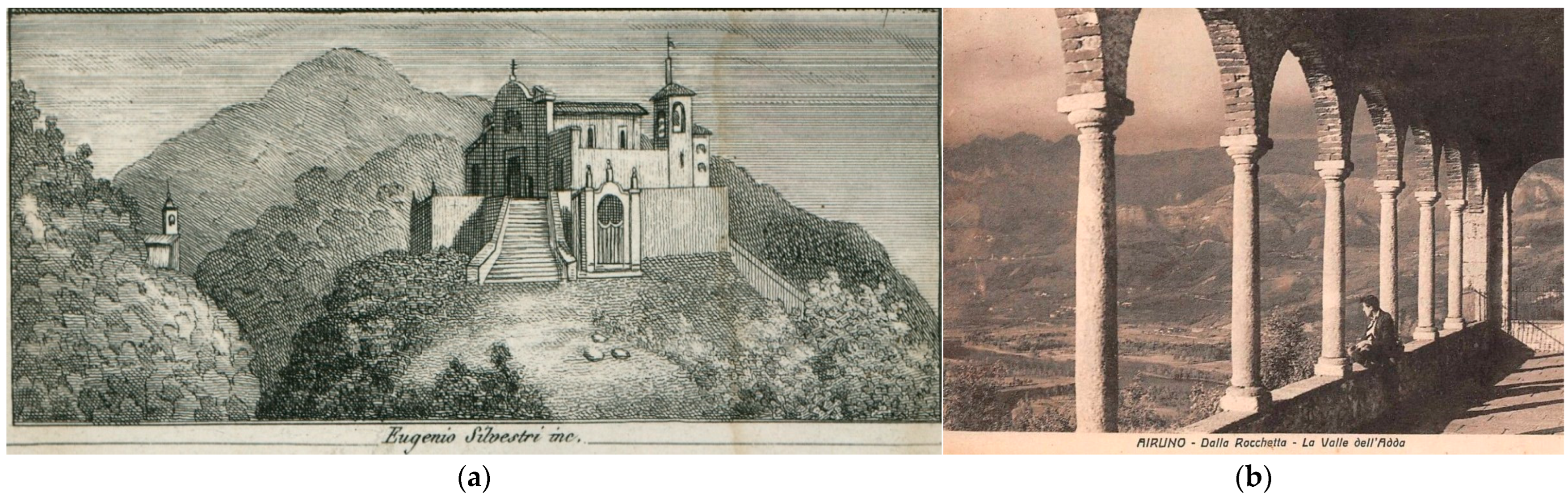
Attached to the castle was a small church dedicated to St. Michael. However, no details inherent in the structure or any decorations have been handed down. In the 1200–1300s, Christian Europe saw the rise of a dense series of Marian places while the existing small churches were dedicated to the Madonna. For the Rocca, precise documents related to that period are lacking, but the transformation of the ancient church of San Michele into a Marian Sanctuary probably dates from that time. In 1571, the small, square-shaped church was dedicated to the Virgin and was called Santa Maria del Castello della Rocca. The conformation of the original building, which in size actually corresponds to the present one, seems to resemble a type of church from the Sforza age with a nave divided into three bays and transverse arches, a ceiling of terracotta tiles and wooden rafters, and a large main chapel with a cross vault raised seven steps above the nave. On the right side were two rectangular windows and a door connecting an atrium preceded by a small sacristy and the houses; on the façade, beyond the portal, was an oculus. The nave was partly rough, partly painted, and partly whitewashed, while there were old paintings in the chapel, which was very damp and corroded to the north. Until the early 1700s, the church maintained in this configuration. In 1599, the name was changed to Santa Maria della Pace, probably because the place had changed from a military fortress to a place of prayer and work. In 1725, the church appeared for the first time with the title Santuario dell’Addolorata and in 1748, the little old church, by then falling down, was completely renovated and modified, taking on the face it still has today as represented in
Figure 3.
Over the course of history, the sanctuary has undergone considerable changes and restoration. The first transformation concerned the exterior, with the construction of the holy staircase (a monumental stairway with Via Crucis stations) and the pine forest, whereas later changes were also made at the architectural level of the church. The construction of a sort of small Sacro Monte (a hilltop cluster of chapels dedicated to Marian cycle episodes and structured thematically [
60]), the construction of six chapels for the mysteries of the Virgin, the double entrance small plaza and, finally, the radical change to the church with the construction of the vaults and the decoration with stucco frames, capitals on the pilasters, and frescoed medallions with Marian decorations, are the main transformations of the sanctuary and its environment. The architecture of the building must once have been Romanesque in style, then hidden by Baroque overtones; the primitive internal structure is Romanesque for several bays: the first two from the entrance are the same, while the third is larger, and the vaults still show the cross-ribbed structure. A gateway made of iron leads into an ancient courtyard to the right of the church, where a 1729-dated well was built on the old bastion of the castle, whose high wall borders the house erected on the superstructure of the old fortification, again with Baroque overtones. Descending the stone stairs are small cells, the probable prisons of the castle in the past, now used as cellars.
To the left of the church, a small loggia, once a terrace, has a wooden postern ceiling. In 1937, a pine grove was added; the idea of building a kind of Sacro Monte dates to 1720, and since then, in addition to the first chapel, which may have already existed, five others were built in the years that followed. In October 1923, to attract new worshippers from all over the surrounding area, the construction of the holy staircase began. This was a monumental work placed between the third and fourth chapels, with a slope of 40°, consisting of 130 steps, which was solemnly inaugurated the following year between a double row of 28 cypress trees and the stations of the Via Crucis. At the top is the Christ sepulchre, completely decorated with depictions of Mary’s sorrows; from here, to the right and left, a further 23 steps lead up to the square and the upper loggia of the sanctuary.
4. The Method
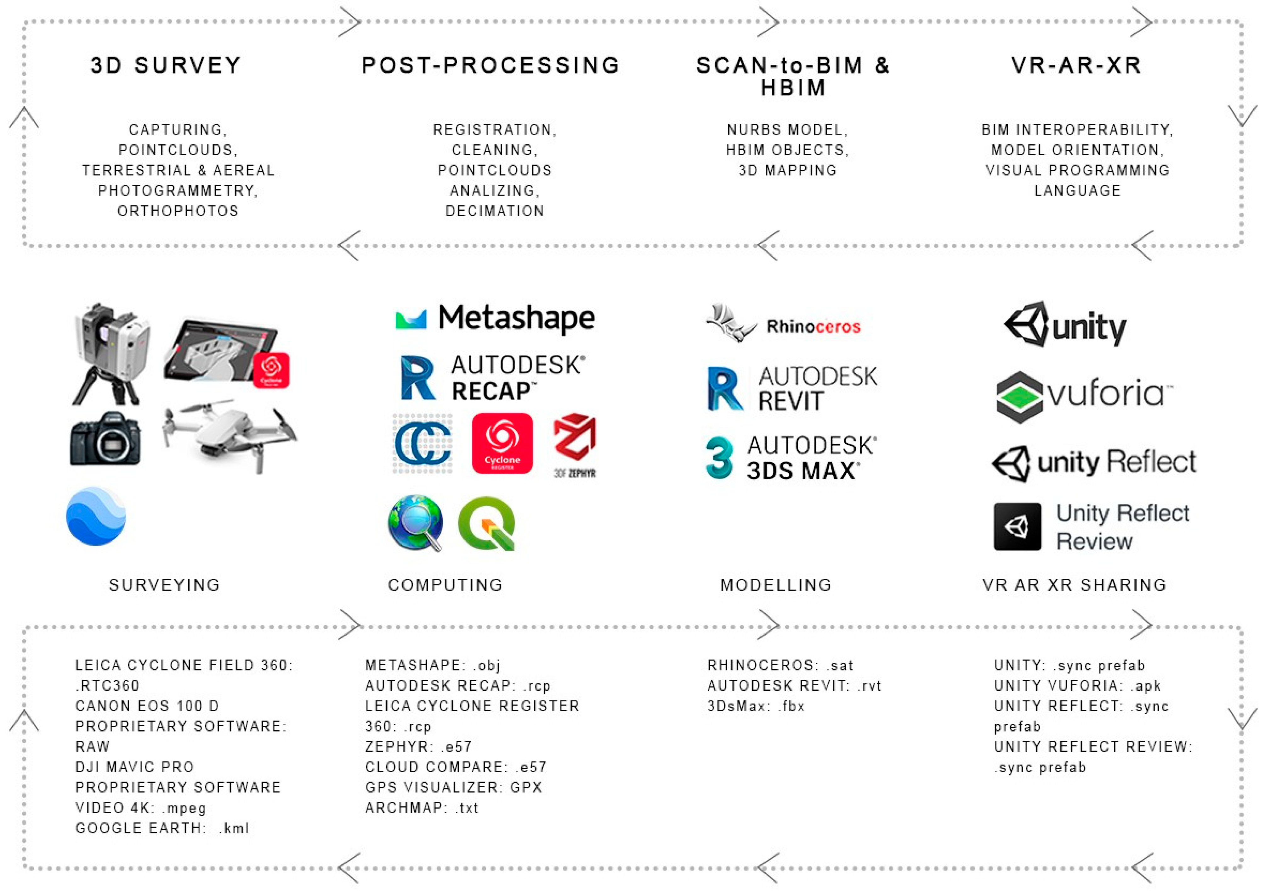
Several integrated surveying techniques were applied to the case study and integrated to prepare an HBIM model; this is realized to be used in an implementable and sharable VR application, as shown in the synthetic workflow of
Figure 4. The application is planned as a test to be usable in the future in all 50 stations of the St. Augustine path for virtual fruition and, eventually, annotation by any kind of user. The stations present different architectures with artistic details and features at different scales: stone sculptures, frescos, stained glass windows, and different morphologies of the surroundings that are not always measurable with standard topographic instruments. The digital survey and modelling phases of the case study were realized to test the various issues that can be met in both stages.
4.1. Laser Scanner Survey
The first phase involved the laser scanner survey project and the subsequent data acquisition. The instrument used to carry out the three-dimensional survey of the sanctuary is the Leica RTC360 laser scanner, acquiring two million points per second. Owing to the support of an integrated HDR imaging, the system produces coloured point clouds with real material pigmentation. The final cloud is made up of 68 scans acquired on 2 different workdays, each lasting 6 hours. The output is a complete point model capable of virtually representing the "state of the art" three-dimensionally with a high degree of detail, but not informed. Most setups were kept at an average density, corresponding to about 1.5 min of acquisition time and an additional minute for photographic capture of HDR images. Keeping the VIS (Visual Inertial System) [
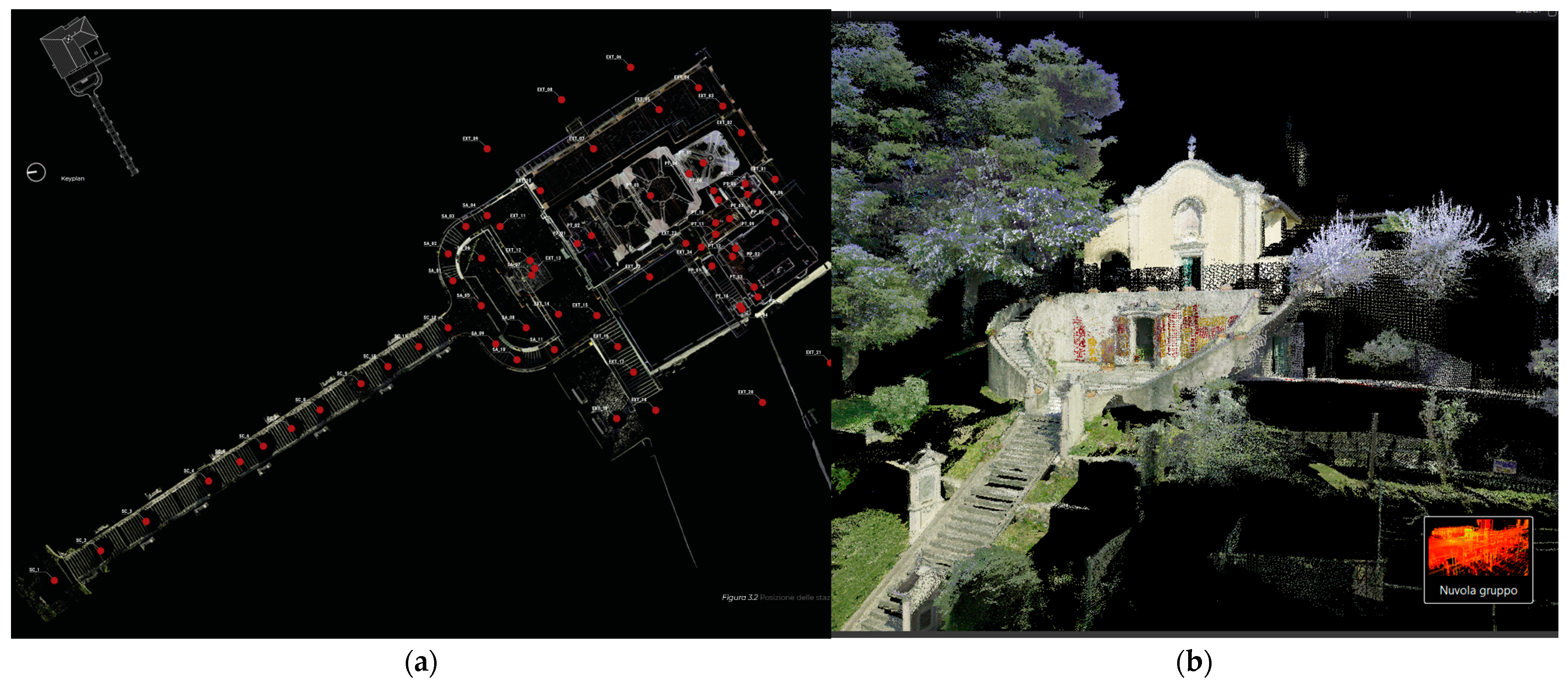
61] sensors active throughout the survey phase, a targetless registration of the different setups can be applied. According to the peculiarity of the area, the density of the points to be acquired is set: low density (12 mm between points 10 m apart), in the case of small environments, and medium (8 mm) and high (6 mm) in the case of larger environments. The raw data processing takes place within the point cloud management program Leica Cyclone REGISTER 360. During the preliminary survey project, five macro areas were identified:
- -
The staircase;
- -
The churchyard in front of the church;
- -
The exterior of the sanctuary;
- -
The interior of the ground floor and the interior of the first floor.
The VIS technology of the instrument allows the placement of the scans in a local reference system, generating a relative coordinate system according to which successive setups are placed. Each single point cloud is pre-aligned using the Leica Cyclone FIELD 360 tablet application. This step simplifies and facilitates the subsequent processing of all scan registrations in the management program. The result of the laser acquisition phase is composed of two main groups of clouds (bundles): the first, consisting of forty-five scans, covers the exterior and interior directly pertaining to the church and its ancillary rooms; the second, consisting of twenty-three acquisitions, covers the holy staircase leading to the sanctuary, the churchyard in front of the church, and the interior of the small sepulchre chapel adjacent to it. The average error related to the scan alignment ranges from 0.001 m to 0.006 m. The groups of scans were merged into a single “point cloud” within the dedicated software.
At the end of the import into the software interface, it is possible to manage the pre-aligned dataset in the following display mode: “Site Map” to view the map of the setup stations; “Cloud Group” to visualise the whole point cloud formed by the sum of all pre-registered scans”; “Cloud connection” to visualise two aligned scans; and “Cloud Setup” to access to the single scan. To ensure an optimal connection, parameters such as the percentage of overlap and robustness defining the global error were kept in check and optimized, adding new alignment connections between stations, becoming 98 links over 68 scan stations. Finally, further visual cleaning of the individual acquisition stations was carried out, consisting of the elimination of overlapping points, points that are far away from the capture area, and noise caused by the light contrast between the interior and exterior of incoherent elements such as open and closed windows and doors in different scans. The general scan map is presented in
Figure 5a and a partial elevation is shown in
Figure 5b.
4.2. Terrestrial and Aerial Photogrammetry
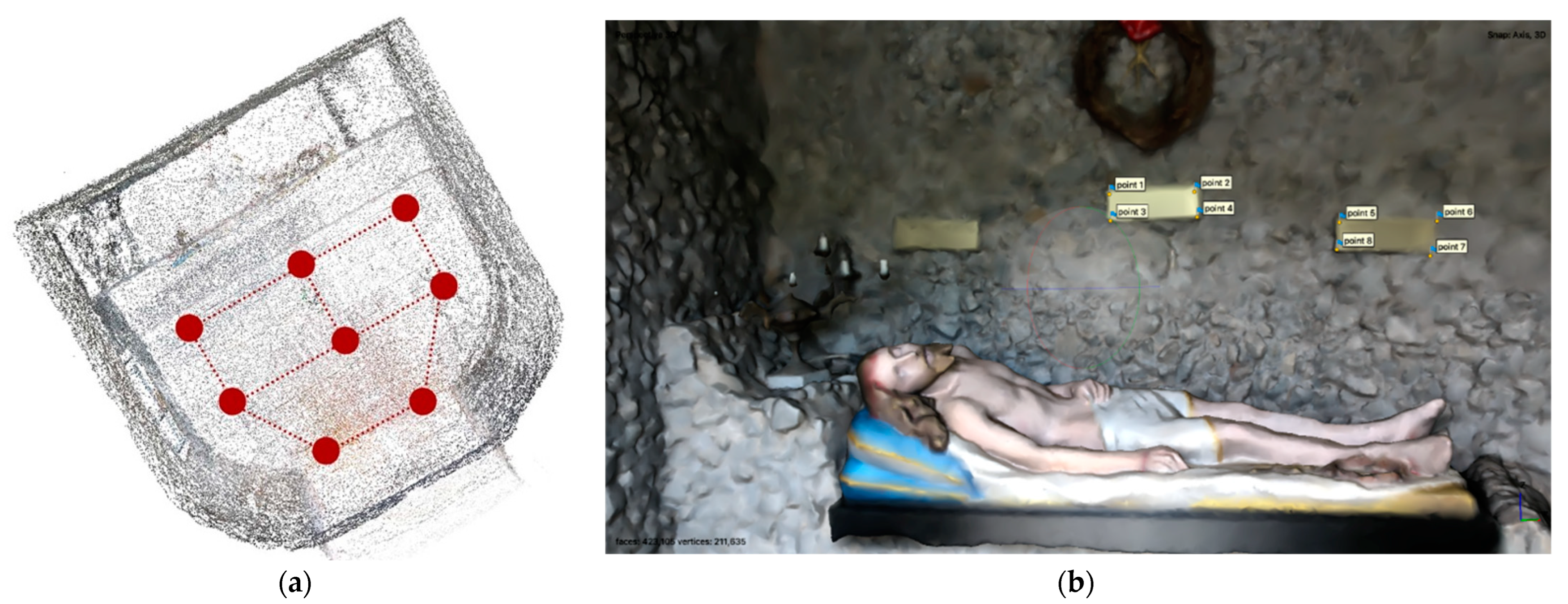
The second survey phase refers to the photogrammetric project required by the peculiarities of some of the sanctuary’s spaces, such as the sepulchre chapel located at the top of the holy staircase and the sanctuary roof, reachable only by drone capture. The close interior space of the sepulchre is rich in details and important texture features. The quality of the laser scanner images was insufficient to provide the proper value of this close interior, as well as some detailed parts of the altar and floor of the sanctuary. The photogrammetry was realized with a Canon digital Reflex camera, model EOS 100D 18-megapixel, CMOS type 22.3 × 14.9 mm, with a Canon E-FS 18–55 mm lens.
The size of the chapel and the peculiarity of its finish made a targetless acquisition possible after having planned a defined path in the plan that would favour a good overlapping of the shots (about 80%), setting a focal distance of 18 mm.
For the generation of the three-dimensional model of the sepulchre chapel, whose acquisition is shown in
Figure 6, the data obtained from the photogrammetric survey are processed in Structure for Motion (SfM) software (Agisoft Metashape). The standard photogrammetric pipeline was applied to process the data [
62]: internal and external images orientation, absolute orientation, and dense image matching. However, in this case, once the sparse cloud is obtained, the mesh is generated directly by choosing the vertex colour mode to preserve the original chromatic info of the object under examination.
The terrestrial laser scanning and photogrammetric survey are integrated with photogrammetric aerial acquisitions [
63]. The drone survey phase was carried out to capture the roofing of the sanctuary with a DJI Mavic Pro equipped with a 4k camera video resolution (3840 × 2160 pixels). The video capturing is used like a photogrammetric dataset. The GCP (ground control points) positions were chosen to act as coherent spatial references in the subsequent processing phase of the collected data.
Once the flight height and distance from the point of interest are defined (using the “Point of interest” function), the drone acquires many frames to ensure a correct overlap and sufficient homologous points among all the images. The data acquisition output is a 360° video with the entire sanctuary as its subject. The drone uses the integrated GPS to define the point of interest position. Once the survey phase is complete, the point cloud can be generated within the proprietary software.
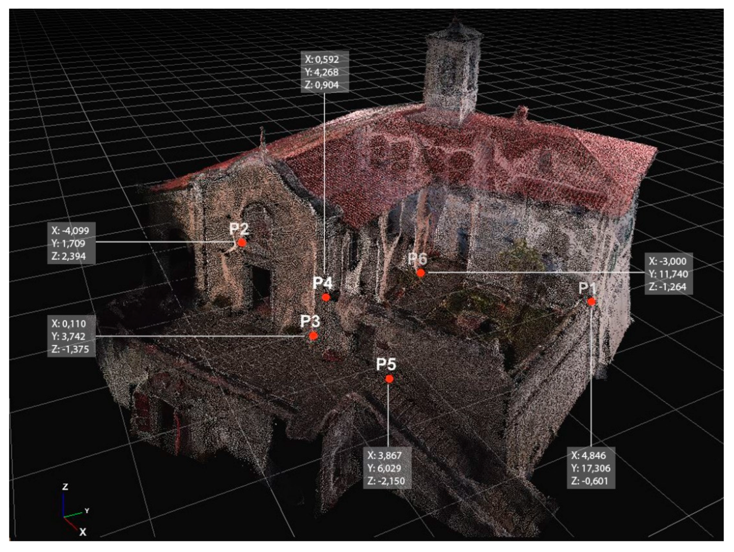
In this case, the point cloud resolution and the noise reduction filter are set to the maximum to achieve the best level of realistic reproduction. From the defined dense point cloud, it is possible to set the surface calculation to generate a mesh and, even better, a textured mesh. Another SfM software (3DF Zephyr–3DFlow) was employed for the data elaboration. After the relative orientation step, the absolute orientation (scale and referencing) is attained using GCPs. The control points were manually identified and selected in at least two frames. Within the “Control Points” panel, it is possible to import a text file indicating the coordinates of the defined GCPs that can be visualised on the 3D point reconstruction, as shown in
Figure 7. After importing the “.txt” file with the (X, Y, and Z) coordinates, the software calculates a residual for each point and a final average residual. The lower the overall residual, the greater the accuracy of the selected point coordinates. The point cloud generated by the laser scanner and processed in Cyclone Register 360 and the roofing point cloud generated by the drone captures within the 3DF Zephyr software have to be registered in the same spatial reference. The laser scanner point cloud is used as a reference system to determine the coordinates of the control point, which were then inserted into the photogrammetric project to orient the roof point cloud. The final average residual obtained is 0.08 m. The final dense point cloud generated from the photogrammetric project is exported in the “.e57” file format in order to be able to use it in Autodesk Recap Pro and create a “.rcp” project; this file format can be imported and managed into the BIM modelling software.
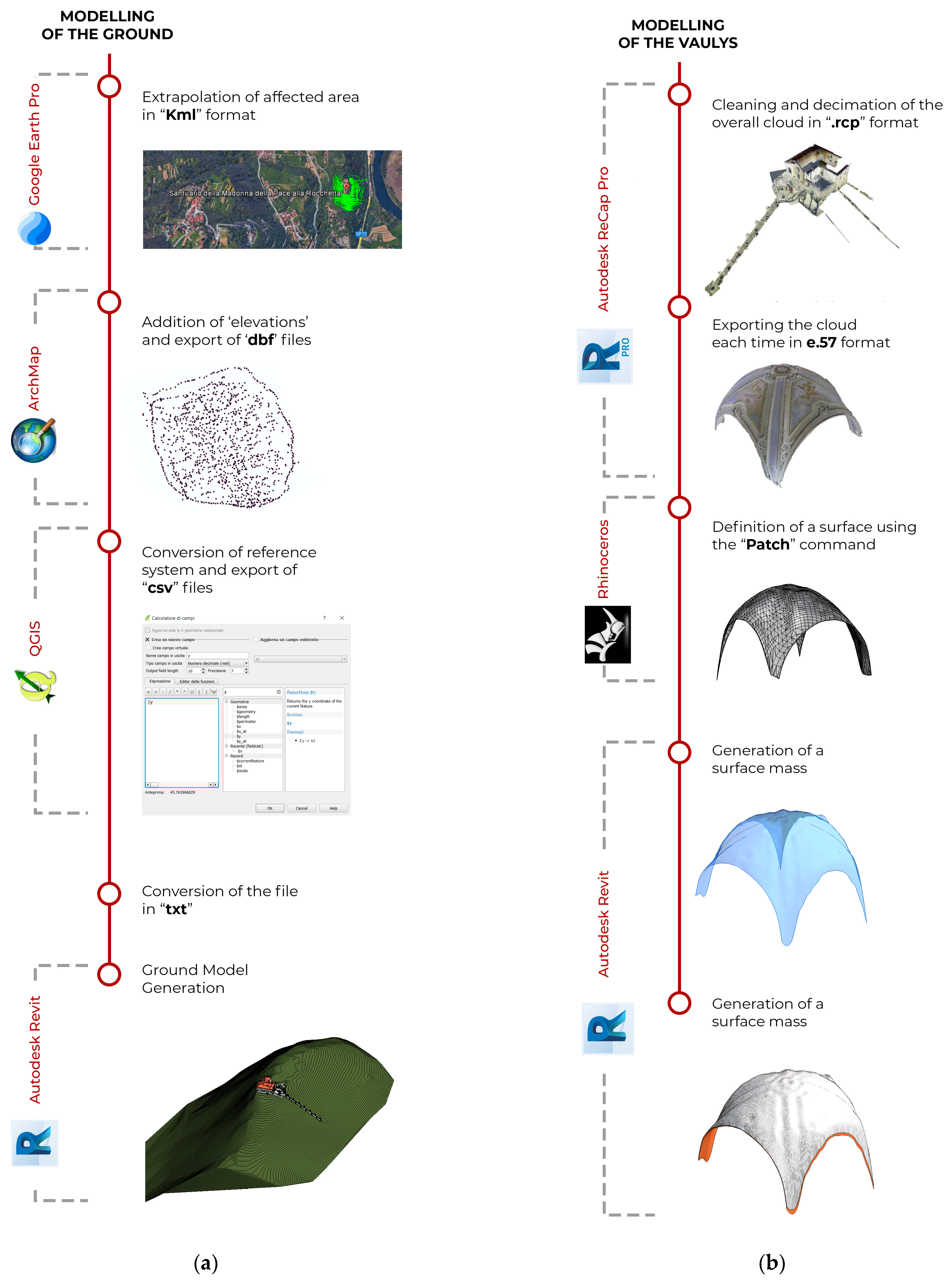
4.3. Google Features
For the generation of the contour lines of the area under study, two procedures were carried out, depending on the portion of terrain concerned. The first method involves saving the point cloud, previously cleaned and decimated a lot by reducing the point-to-point spacing, in a “.txt” file format through specific software for the 3D point cloud editing (e.g., Autodesk Recap Pro and CloudCompare [
64]). This type of file extension can also be used in 3D modelling software.
In the case of larger topographic surfaces demanding to be quickly surveyed, a set of points with coordinates was carried out from Google Earth Pro referenced in the WGS84 coordinate system. Through geographical data visualisation and analysis software (ESRI ArcMap and QGIS), the coordinates of the x, y, and z points of the required portion of the terrain were obtained. This artificial point cloud is ready to be inserted into the modelling software using the form of a “.txt” or “.csv” file. This approach to modelling the context around the building is available for any area and terrain also related to other sanctuaries along the path. First, the profiles are drawn across the entire area in Google Earth Pro that follows the course of the topographical surface; the points are then exported in “.kml” file format based on XML used to represent geographical features. It is, however, necessary to add the “elevations” and convert the file to a GPX format. The file can be saved through ArcMap in the “.dbf” format, and then through QGIS its reference system is changed to “WGS84/UTM zone 32N, EPSG:32632”. By selecting the project layer, the x and y coordinates are added to the z coordinates already present, and the project is then exported in CSV format by selecting “WGS 84 / UTM zone 32N, EPSG:32632". This final CSV file contains the table with the x, y, and z coordinates of the points, which can be read via Notepad and are ready to be imported into the modelling software.
4.4. Modelling Phase
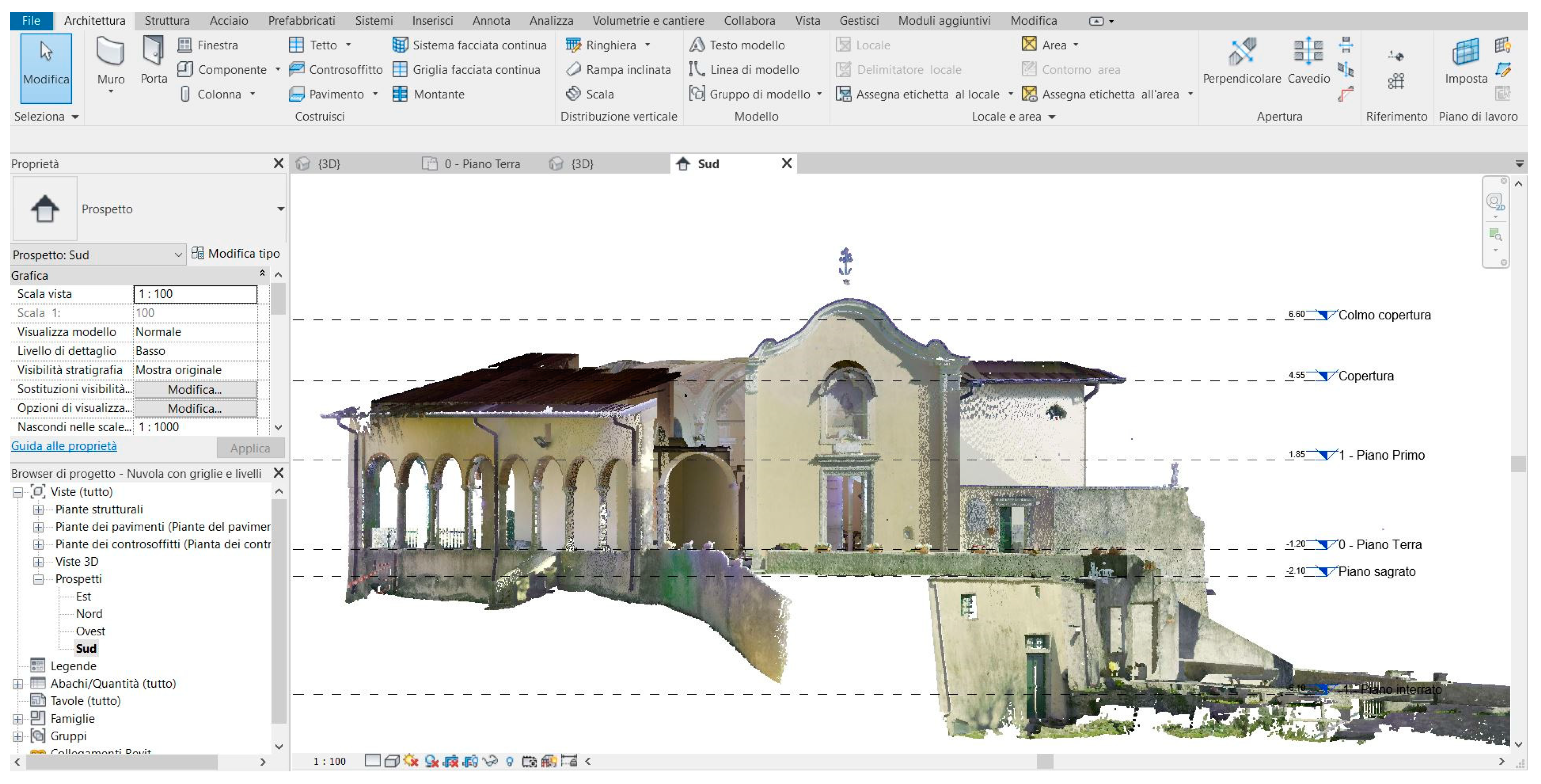
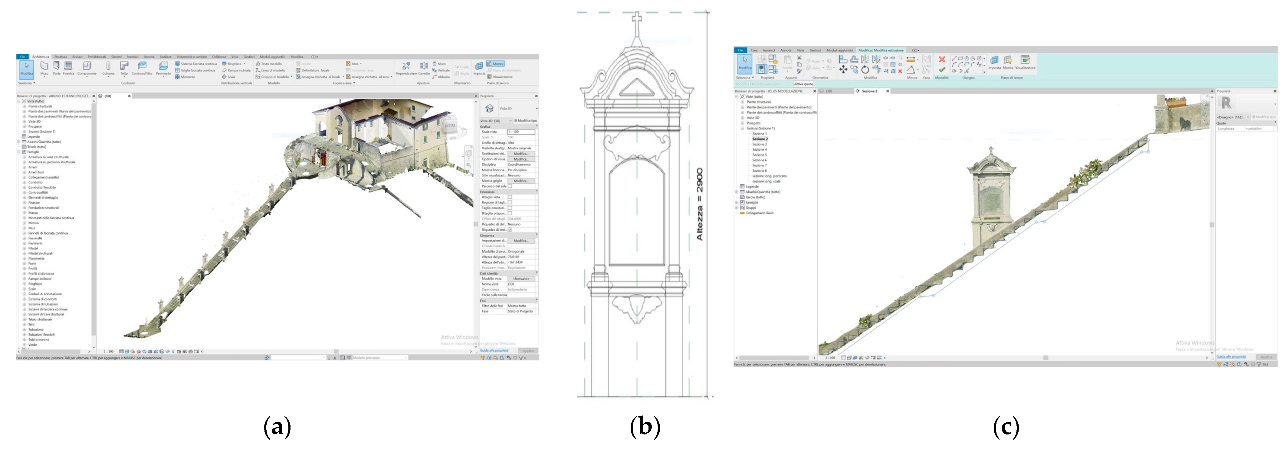
Following the survey phase, a precise modelling phase is carried out. The aim of the HBIM model of the sanctuary is to have a three-dimensional representation of the site, as realistic as possible, for its use in VR applications; the applications planned are intended not only for the virtual fruition and knowledge of the place and its history but also as a technical tool for annotation from technical stakeholders for maintenance or public users. To achieve this goal, it is necessary to recognize the semantics of the different architectural objects of the surveyed point cloud so that they can be modelled as digital BIM objects; moreover, it is necessary to identify the relationships between the objects, cataloguing them by means of families. The first phase of the modelling consists of importing the complete point cloud derived from the laser scanner survey as a geometric reference on which the geometries of the digital reconstruction can be realized. The imported point cloud “with shared coordinates” is indexed to allow each point in the cloud to be recognized as a snap within the work environment of Autodesk Recap Pro (v.23.0) software. The point cloud is oriented so that the north direction of the cloud file is associated with the true north of the modeler’s model. The point cloud is used as a reference for restitution with a level of detail compatible with the 1:50 scale of representation, which is sufficient for modelling geometries with an accuracy within half a centimetre. Within the modelling, a maximum error of 30 mm was therefore maintained. For the definition of the primary geometries within the model, the main levels are laid out with good accuracy to ensure a reference for the majority of the objects: a plane corresponding to the ground level of the portico and churchyard, and a plane for the level of the pine forest outside the portico and roof level (
Figure 8).
Following the profile of the main body and exteriors, the modelling of the holy staircase and the sepulchre chapel were carried out [
65]. After drawing reference lines and planes, the perimeter walls enclosing the entire area of interest in the modelling are defined; floors and non-structural and decorative elements are subsequently added. Within the sanctuary model, generic system families are used for the masonry and floors, as there is no documentation of the correct stratigraphy data; the thicknesses obtained from the point cloud are exact, and this information helps the implementation of the model in the following phases. As far as the floor levels are concerned, the point cloud indicates that the floors inside the church and the annexed rooms have a slight inclination, so within the modification of the floor parameters, the inclination property is set to the side of the perimeter concerned with defining the degree of inclination. Numerous loadable families are used within the model to customize the individual non-structural elements of the architecture. A type parameter controls all the elements located in the drawing area and an instance parameter concerns the specific properties of each element placed in the drawing, considered individually. The building geometry is created using the modelling tools that the family editor of the BIM modeler used. Autodesk Revit makes the following tools available: extrusion, union, revolution, extrusion on path, and union on a path. The technique of nesting families (one family within another) is adopted to create windows, as represented in
Figure 9a, allowing the sub-components, e.g., the sill and the shutters, to be modelled separately. The elements modelled are loaded into the main family, called the host, and nested through parameter association; this allows the parameters of the nested families to be linked to the parameters of the host family.
For the modelling of exteriors, different types of loadable families were generated, taking as reference the “Portico Columns” family, used for the columns that follow the perimeter of the entire portico. The different components of the column are modelled, such as shaft, capital, and base, each bound to reference planes useful for creating parameters. The loaded "Portico Columns" family was used to model all the columns along the perimeter of the external portico, duplicated and renamed for each column. The type was modified through the parameters previously created. Therefore, within the working project, one has a single family for these components and a series of different types relating to each column, renamed and customized. The holy staircase (
Figure 10a,c) hosts the aedicule shown in
Figure 10b. It was modelled as a system family, with thirteen copies inserted within the project, which are modifiable according to the specific characteristics of each.
Once the basic structure of the aedicule object has been defined, it is possible to start modelling the various parts, such as the frame, mouldings, and decorations, using the tools in the family editor; each element is always bound to specific reference planes for the creation of parameters. Local families are used to model all the unique elements as little as possible within the project. In case of duplication, the program reads the copies as individual elements, hindering any computation operations.
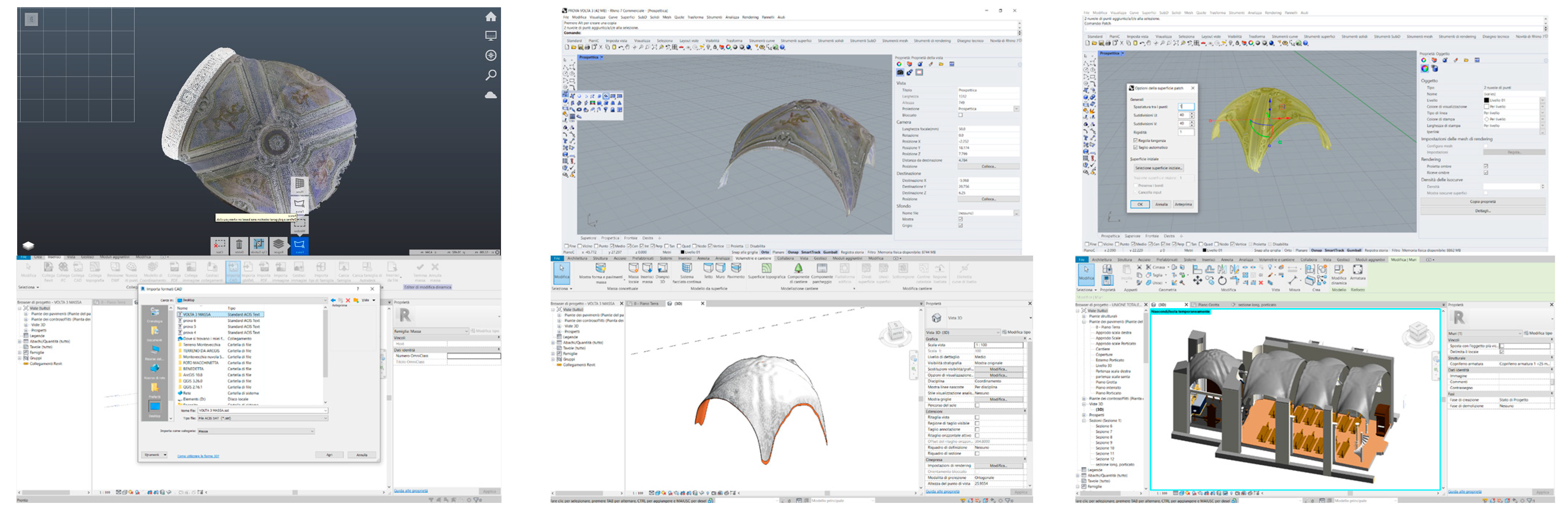
The vaults modelling shown in
Figure 11b is a synthesis demonstrating how much the integration of several modelling types is necessary to manage and inform the shapes. Instead, the vaults within the model are extremely irregular and deserve case-by-case treatment; imported from the point cloud within Autodesk ReCap Pro, they are selected one by one, deprived of context and exported as individual projects. In the export settings, 20 mm is set between the various points to then be imported into the NURB modelling software Rhinoceros. It is important to check that the unit of measurement of the new “.3dm” project is the same as the Revit BIM modeller project. An automatic generation of a surface from the point cloud by selecting the “Patch” command can be realized within the command panel for defining surfaces, defining the spacing between the points, the U subdivisions (the number of subdivisions in the U direction for the automatically generated surface), and the V subdivisions (the number of subdivisions in the V direction for the automatically generated surfaces).
The generated surface is perfectly adherent to the starting point cloud and can be exported, in the form of a “.sat” file, to be opened in the BIM modeler as a local. Given the irregularity and complexity of the source surface, a new type of wall with a thickness of between 0.5 and 1 cm is then defined, so that the item can be easily generated. By selecting the previously generated mass, the “Roof from surface” command allows shaping the “Roof” architectural component that traces the geometries of the vault concerned. The operation of importing and modelling the new architectural components is repeated for each of the four vaults of the church and correctly positioned within the model, and then the “.dwg” file containing the model of the sepulchre chapel is inserted. After the modelling phase of the exterior of the sanctuary and the church has been completed, the three models are merged into a single environment. The base model containing the church is the one to which all the remaining models are connected using the “Connect Revit” command in the “Insert” section, selecting the positioning option “With shared coordinates”. Once the process of joining the three models is completed, the roof modelling was provided by implementing, within the project, the cloud generated by the drone.
Two different workflows were used for ground modelling, as shown in
Figure 11a. The choice depends on the source data used: the point cloud model realized from the laser scanner survey, cleaned, decimated, exported in ACIS “.txt” and then exported to the BIM modeller, or the file created via “Topographic surface” and its advanced options “Create from import-Specify point file”, viewed in the plan view “Building site” of the BIM modeller. In the second case, the final CSV file obtained using the Google Earth procedure containing the table with the x, y, and z coordinates of the points is inserted inside the Autodesk Revit software in a new project by selecting the “Topographical surface” tool from the “Volumetry and building site” table. The “.txt” file is inserted using the “Specify point file” command in “Create from import” by selecting the text file so that the software automatically models the topographical surface. Within the software, the terrain is correctly oriented according to true north in space. For an exact overlapping of the terrain with the Airuno model, it is, therefore, necessary to orient the latter. In the properties window, the “design north” is changed to “true north” (in the “orientation” box) and the model is merged with the previous one.
5. The Results
Modelling complex morphologies from point clouds for BIM applications (both modelling system family, loadable, nested, as well as modelling complex objects—vaults obtained by NURBS surface modelling) combines the desired precision of a process with the difficulty of returning the object surveyed exactly as it is, as shown in
Figure 12. This aspect has been the main driver of the whole scan to BIM process.
Image-based procedures based on automatic image matching have been used to create 3D reconstruction of point and mesh models [
66]. Advanced modelling techniques using meshes obtained from photogrammetry have been introduced into the BIM workflow to obtain the accuracy of a BIM object. Point cloud control tools of complex parts within the modelers have been used to create NURBS suitable for most heritage modelling types. Semantic attributes have been added to objects built outside the BIM modeler achieving at least as accurate a 3D representation as possible. The standard deviation between a point cloud and the respective NURBS has been determined through specific algorithms and software tools. Textures have been generated through photogrammetry; high-resolution orthophotos have been inserted as decals into different surfaces of the model objects, defining their materials as the first stratigraphy so that the last layer of the BIM object is the detected materials.
The first result of the data processing is a point cloud of more than 2 million, distributed in 68 scans, registered in the same coordinate system using a cloud-to-cloud algorithm through 98 links. The average overlap between pairs of scans is 53% with an average alignment error of 0.003 m. As a second result, the survey was followed by a complex modelling phase with different software, which was completed in a BIM environment to obtain an accurate, informed model of the existing heritage. The model was enriched with photogrammetric reconstructions of some parts and textures, in cases that needed more detail. From these significant results, the following two goals were accomplished: a prototype of an app for sharing the visualisation of the place with common devices; a second application for technical staff or common participation in the process of observing the state of the architecture and places.
5.1. First App for Wide Share
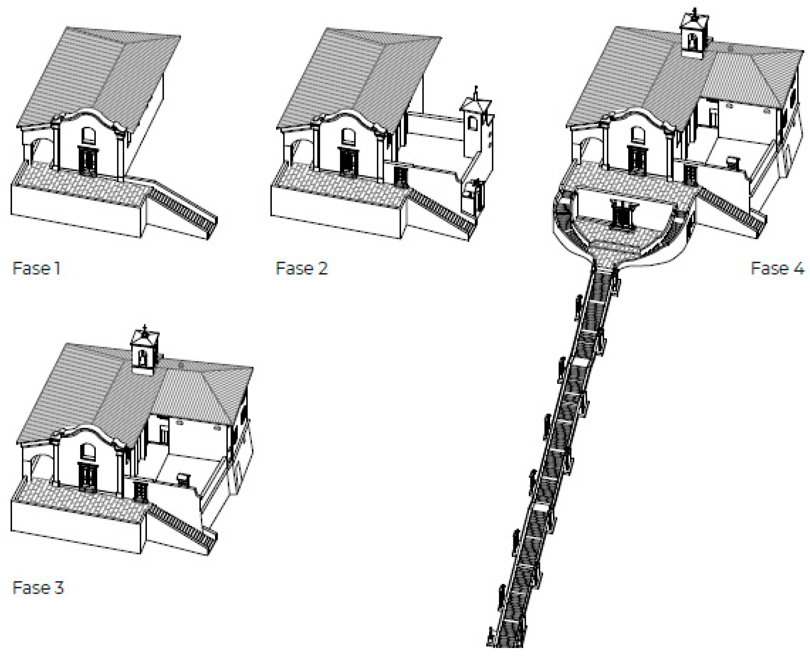
The first application utilizes a commercial application that takes advantage of AR technology. The objects of the application are the four previously made timed three-dimensional models of the sanctuary represented in
Figure 13 to be explored and visualised by smartphone. The timing phases of the model were defined in the BIM modeler, knowing the temporal sanctuary evolution and the transformations that have occurred. After controlling the knowledge of the property with iconographic and historical materials, the phases are created within the “Manage Phases” panel, where it is possible to control the general management of phases and filters related to them. The phases required for timing in chronological order are added, and filters are set for the graphical display of modelled objects. The previous architectural phases were added starting from the sanctuary model referring to the current state. Each element within the properties is linked to a construction phase. By duplicating the views, it is possible to display them at the desired phase by setting the phase filter in graphical display mode.
The selected evolutionary stages, with their modifications, are (
Figure 13):
- -
1571, the church corresponds, in form and position, to the present;
- -
1610, the state changed with the construction of a new tower for the bell joint to the chapel on the southern side;
- -
1730, the atrium where the votive offerings are kept, the sacristy, the bell tower, and the upper floor with the hall were added;
- -
1924, the holy staircase, located between the third and fourth chapels, consisting of 130 steps and accompanied by the aedicule of the Via Crucis was realized.
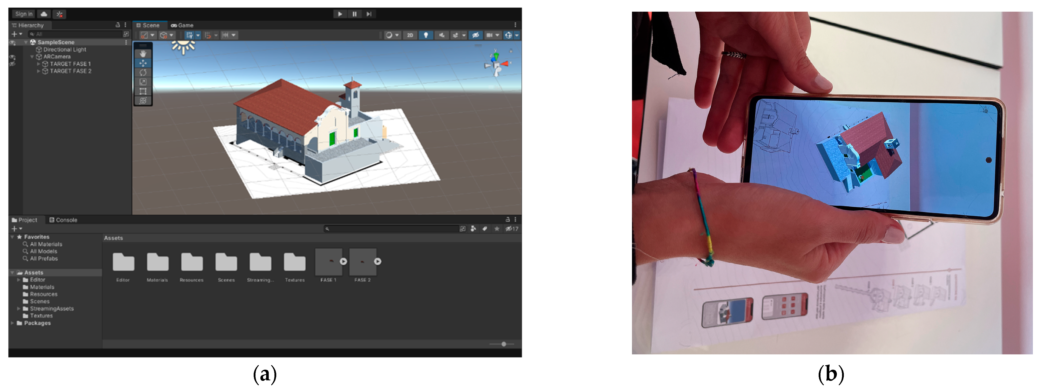
A smartphone prototype application was created, taking advantage of AR technology to show the evolution of the model over time to as wide an audience as possible; the four three-dimensional models previously made are the issue shown. The plug-in used is downloaded in the Unity Reflect assets and chosen as belonging to the same development environment as the next application. Once the process of texturing the models of the individual stages was finished, they were exported in “.fbx” file format. Each textured model requires a scene conversion using Autodesk 3ds Max software to be read in Unity Reflect. By individually importing the models in “.fbx” format within the software, it is possible to convert the scene by setting the conversion setting of standard materials to real materials. This last step allows importing the models within the AR development software. Changing the settings of Unity Reflect enables working with the Vuforia AR Support mode [
67]. After importing the “.fbx” files containing the four phases of the model into the “File/Building Setting” section and then into the “Player Settings”, in the “Inspector” area it is possible to access the properties window to change the settings found in the XR Setting field, choosing the AR mode. Then, an image target, the visual marker for creating AR, must be loaded, as shown in
Figure 14.
The target image for each of the individual phases chosen is its corresponding floor plan so that by framing each of them in sequence, it is possible to visualise the timed sequence of the four models. In the demo case of this sanctuary (as one of the 50 steps of the cultural path), the proposal is ready to be concluded with a plaque prominently placed in the sanctuary to provide all users with information about the building development across the years and in general to create a greater understanding of its components and construction phases. Finally, to make the sanctuary’s historic transformation accessible to tourists over time, the four 3D models created can be easily explored and viewed by any user via smartphone. Moreover, it is precisely from the relationship between the individual objects and the different construction phases read synchronously that the architecture’s general balance and eventual states of degradation can be more fully understood.
5.2. Second App for Stakeholders or Common User Annotations
The development of platforms for virtual enjoyment can increase the knowledge of the CH both in terms of the number of users and in terms of increased spatial understanding [
68]. New platforms have now been absorbed within cultural dissemination workflows; the use of affordable headsets has grown the level of interactivity through software that manages visual program languages. The simplest tools found in the literature of even video gamers [
69,
70,
71,
72,
73,
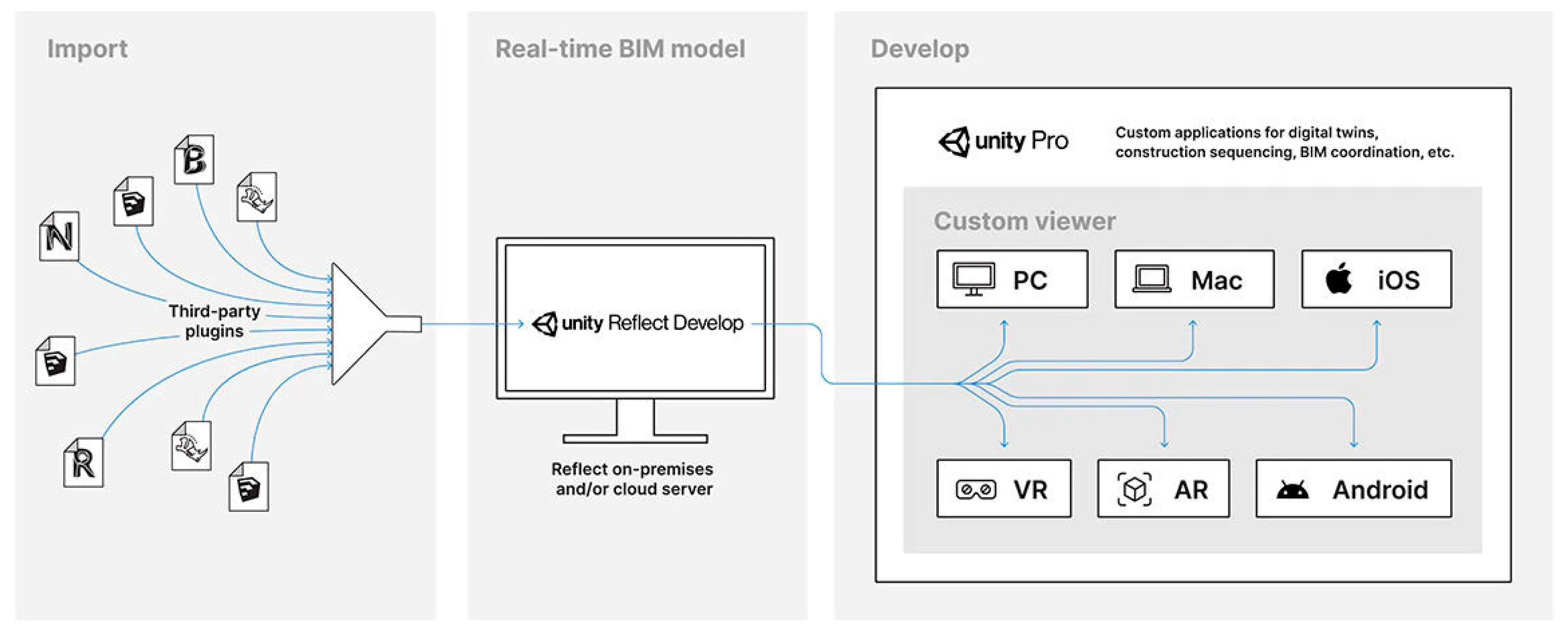
74] range from interactions with objects, parts of the model, or the entire model, to third- or first-person factual enjoyment through increasingly immersive experiences. Increasingly refined textures applied to the Unreal Engine model can simulate real environments. However, the peculiarity of a BIM model to contain information that can be queried, shared, and augmented does not find its best performance in pure visualisation software. In the case study, therefore, experimentation was carried out using model visualisation in VR on different devices through a new feature of the Unity Reflect package, whose interoperability is shown in
Figure 15.
Unity Reflect is compatible with the latest versions of several modelers, including the BIM environment used, and was created to implement AR and VR technologies in a better relationship. It is specialized in converting 3D objects between modelling software (architectural side) and the Unity Reflect editor (technological side). This feature opens a wide range of opportunities for developing custom applications that include modelling skills of 3D software and application versatility with Unity Reflect. It retains all the information of the original informed BIM model and allows interaction between multiple users in a cloud, a virtual environment, to share annotations and changes on the same shared object. The software utilizes the Unity Reflect Develop feature to create a custom Unity program allowing the importation of our model created in Revit to be visualised with new tools for annotation and technologies coded with the Unity editor. This application’s purpose consisted of implementing a user-friendly pipeline between modelling software (such as Revit) and VR/AR technologies and devices, developed with the specific intent of being utilizable with little to no technical knowledge of the underlying Unity and Unity Reflect technologies. Unity Reflect provides a collaborative annotation feature that allows users to select an object and write an annotation on it. These annotations are visible to all users and can be replied to, deleted, or edited by permitted users. Importing the Airuno Sanctuary model into the software allows simultaneous visualisation in different devices, due to the model host being in a proprietary sharing environment. It is necessary to have a Unity Reflect Review license to utilize these features and other Unity Reflect Review tools (such as BIM information visualiser, filter, and measure tools). It is worth mentioning that it is also possible to purchase Unity Reflect Collaborative licenses for view-only usage; non-registered users with a link-sharing system can dynamically utilize these licenses.
The innovation of the platform tested lies in its simultaneous connection between the actual modelling environment of the Revit project and the virtual environment created by Unity Reflect. Formally, multiple actors can view updates while working on the same model. The procedure followed used the import from Autodesk Revit 2021 and performed the synchronization in Unity Reflect. The latter appears as a plug-in inside the Revit interface, allowing synchronization between the two software. Upon opening the project, the 3D export icon was selected right away. The platform allows storing projects either locally on a local network, or in the cloud, thus providing the possibility to develop a project that can be expanded on a large scale as a possibility for the whole cultural path. The desire to visualise specific textures inserted into the BIM model from orthophotos made during the acquisition phase was verified.
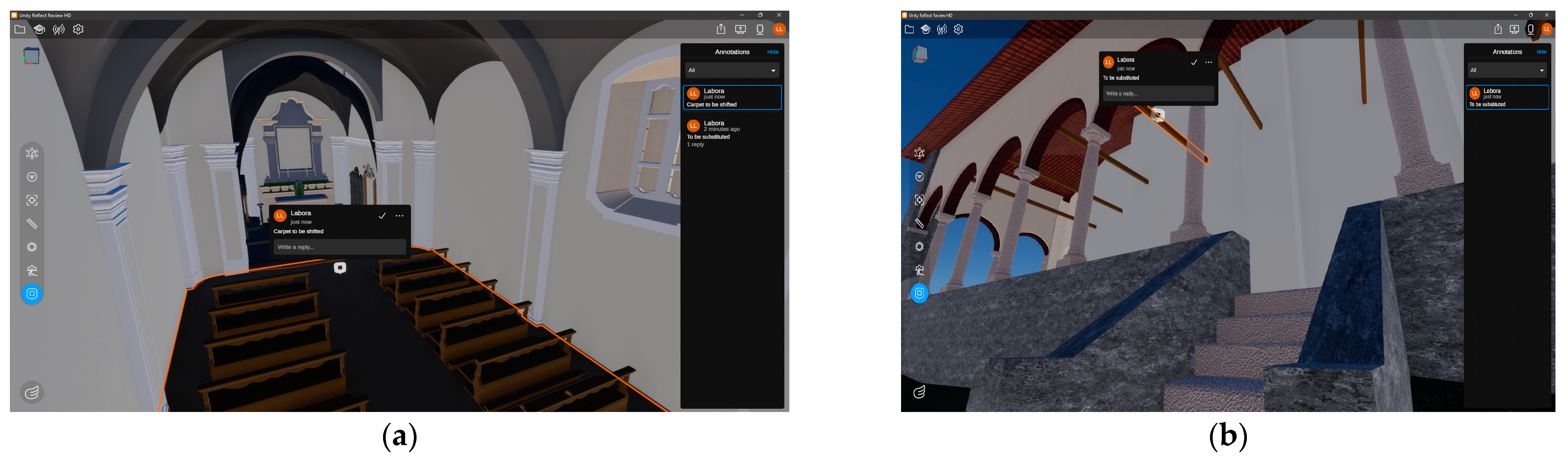
Unity Reflect already has among its tools the ability to isolate elements; in this way, you can share the same framing by selecting the part of the textured building that you believe is the subject of the annotation with other users, as the Reflect update provides the ability to make annotations on the model that can be shared for the recovery project (
Figure 16). Through annotations, users can enter comments that become direct links to be directed within the model; the annotation is visible in the model in the scene annotated by the reviewer. Notes can be organized in legends according to any rule and the degradation of a material annotated on a specific texture is site-specific and will always return the user back to the scene in which they originated. Projects placed in a cloud can be shared with anyone, on any device, through a URL.
7. Conclusions
The constant research work in this field allows the definition of strategies and goals that can be refined and implemented over time, thereby offering guiding paths for the digitization of different types of buildings. The whole workflow shows how to transform survey data into an informative model to be explored and annotated regarding different types of knowledge associated with complex heritage geometries. Due to the level of expertise required to safeguard the accuracy of the first phase of digitalization, it can be complex to return the same level of model accuracy and details to a broad audience (that may be less familiar with this type of technical representation) as well as to a specialist audience oriented to a design and maintenance phase. The creation of immersive VR environments must be organized as simply as possible to maintain a non-exclusive level of use, offering easy-to-use tools accessible to any user for enjoyment and annotation. Therefore, even if the last steps of this process are 100% fully customizable, this aspect implies the need for advanced programming and developer skills. It is possible to imagine, in constant monitoring of heritage monuments, the use of shared tools and data; for example, within a public conference, the designer can illustrate the stages of maintenance and renovation of the building directly in the shared environment of Unity Reflect, where the models have been enriched. In this way, alongside the support of panels, images, and videos, there would be the fruition of the analysed and classified model in the materials through the added textures, annotations, and classifications on the state of degradation to which recovery proposals can follow. However, this model, which can also be implemented for broad participation, presents some issues that still need to be resolved. Other non-secondary issues should be addressed in future developments. From the point of view of content, Unity’s translation of transport models into Unity Reflect maintains the accuracy of details and materials added but still suffers from essential simplifications: the internal definition of the modelled objects is still absent. The definition that gives the justification for BIM modelling exists in the textual part but not in the internal geometries of the object. If very probable software development is to be expected, the huge model file size eventually obtained could be another issue. The second point that needs to be considered concerns the onerousness of licenses for the visualisation of models in the same environment as well as the ownership of the shared environment itself. The analysis performed in Unity Reflect rewards activities and applications developed are implementable. The research also rewards ease-of-use but forces considerations about use in the large scale of public assets as in the virtual app developed. A third point concerns the construction of the entire virtual environment within which to develop the relationship between different user experiences. The model has now been acquired as such, but the whole virtual environment that contains it could also be customized and made more performant for different experiences, from common users to experts stakeholders.


