
The Structural Behaviour of Tension Steel Rods Strengthened with Carbon-Fiber-Reinforced Composite Materials
Department of Metal and Wooden Structures, National Research Moscow State Civil Engineering University, 26, Yaroslavskoye Shosse, Moscow 129337, Russia
*
Author to whom correspondence should be addressed.
Buildings 2023, 13(2), 375; https://doi.org/10.3390/buildings13020375
Submission received: 12 December 2022
/
Revised: 6 January 2023
/
Accepted: 10 January 2023
/
Published: 29 January 2023
(This article belongs to the Special Issue Safety and Optimization of Building Structures)
Abstract
:Strengthening can increase or recover the bearing capacity of steel constructions of buildings and structures in operation. Besides well-known strengthening techniques, including an increase in the sectional area by means of attaching steel plates, angles, channels, pipes etc. to a strengthened element, other methods, that involve the use of carbon fiber-reinforced composite materials, have strong prospects. So far, the structural behaviour of steel constructions, strengthened with carbon fiber-reinforced composite materials, is understudied, and this fact restrains the practical application of this strengthening method. The article presents the results of complex experimental, theoretical and numerical studies of the features of the operation of steel-stretched elements reinforced with glued carbon fiber. The emphasis is on the load-bearing capacity of the reinforced element, and not on the mechanism of destruction of the glue. This is due to the use of an adhesive joint performed using the glue and gluing technology recommended by the manufacturer of carbon fiber. It has been experimentally established that, in this case, the stresses in carbon fiber cannot exceed a certain value. Theoretical dependences for the calculation of CFRP-reinforced steel stretched elements are proposed. The scientific novelty of this research project is a set of basic principles and methods, developed to identify the bearing capacity of steel rods, strengthened with carbon fiber-reinforced composite materials, taking into account the joint strength performance of a steel rod and adhesively bonded carbon-fiber-reinforced composite material, as well as the new findings thus obtained, such as the theoretical dependencies needed to identify the bearing capacity of steel rods strengthened with carbon-fiber-reinforced composite materials; experimental data on the joint strength performance of carbon-fiber-reinforced composite lamellas attached to a steel rod by an adhesive; experimental data on the performance and the bearing capacity of steel rods strengthened with carbon-fiber-reinforced composite lamellas; development of finite element models of steel rods strengthened with carbon-fiber-reinforced composite materials, and computational studies of steel rods strengthened with carbon fiber-reinforced composite materials.
1. Introduction
In addition to traditional materials (timber, concrete, steel), polymeric and carbon-fiber-reinforced composite elements are widely used to make building structures [1,2]. Polymeric composite materials are successfully applied to strengthen reinforced concrete and timber structures. The low modulus of elasticity of polymeric composite materials does not allow them to effectively strengthen steel structures. Unlike polymeric composite materials, carbon-fiber-reinforced plastic (CFRP), produced in the form of straps, meshes or lamellas, has the modulus of elasticity comparable to that of steel, and its strength exceeds that of steel multifold. The joint structural performance of carbon-fiber-reinforced plastic and steel elements will substantially increase the bearing capacity of a steel structure in tension. Given that the strength of CFRP is high, it can substantially improve the bearing capacity of steel rods, if used as reinforcement.
Composite materials, used to strengthen steel structures, have been studied by a number of authors. In [1,2] the authors address problems of the joint structural performance of fiber-reinforced composite materials and a steel structure. In these works, attention is focused on the need to carefully prepare the surface for the reliable adhesive bonding of steel and composite materials. The fatigue strength of this joint and the influence of adhesively bonded composites on the local stability of a steel element are considered. The behaviour of a steel beam reinforced with carbon-fiber-reinforced plastic is studied, and the findings enable the authors to develop numerical models used to evaluate the bearing capacity of strengthened beams [3]. The tension, arising in CFRP strips near the holes of beam webs, was studied in [4]. The authors suggest that the joint structural performance of adhesively bonded CFRP strips was efficient, and the bearing capacity of castellated beams was higher.
The effect of polymeric materials, strengthened with carbon-reinforced fiber, adhesively bonded to the surface of steel plates, on the plate cracking was studied in [5,6]. The authors experimentally found that cracking was down when CFRP with a high modulus of elasticity was used.
The authors of [7,8,9,10] conducted experimental and theoretical studies of the effect of carbon fiber strengthening on the performance of beams. The authors of [7] suggest applying CFRP as a means of strengthening a beam web to rise its shear bearing capacity by ensuring the joint tensile strength of CFRP and the beam web along the tensile diagonal line. Works [8,9,10] study the stages of strengthening as a means of rising structural strength, as well as the effect of strengthening on the bearing capacity and rigidity in case of (1) localized loading, (2) a variable length of the strengthening strip, taking into account the strain of carbon fiber-reinforced plastic and the adhesive.
The local stability of thin-walled steel profiles can be substantially increased by bonding CFRP to the profile surface [11,12].
CFRP can effectively strengthen tensile steel rods [13,14,15]. In [13] much attention is paid to the adhesive bonding of CFRP to steel. The behaviour of this layer determines the tensile behavior of carbon fiber-reinforced plastic. In [15] the method of analytical and finite-element modeling of tensile elements, strengthened using carbon fiber-reinforced plastic, is presented. The study of multilayered (cascade) strengthening of tensile elements, using composite materials, is presented in [16].
The effect of different adhesive-bonded joints on the performance of strengthened structures was studied in [17,18]. The dependence of the strength of adhesive bonding on the roughness of the surface to which the composite material is bonded was studied in [19]. It was found that the condition of the surface had little influence on the strength of adhesive bonding.
The analysis of the stress-strain state of CFRP-strengthened steel structures can be rationally performed using the finite element method [20,21,22]. In the numerical analysis of strengthened steel structures, much attention is paid to the simulation of an adhesive joint by means of which CFRP and a steel element interact.
Certain experience was accumulated and a method of experimental studies of steel structures, strengthened by carbon-fiber-reinforced composite plastic materials, was developed. Tests, involving strengthened specimens and structures, allowed obtaining objective data on their actual performance [6,10,23].
Recommendations on the analysis of steel elements, strengthened by carbon-fiber-reinforced plastic materials, were developed. CNR-DT 202/2005 “Guidelines for the Design and Construction of Externally Bonded FRP Systems for Strengthening Existing Structures” have a method for the structural analysis of elements in bending and in tension.
Hence, certain findings were obtained as a result of experimental, theoretical, and numerical studies of steel structures strengthened by CFRP. The finite element method is efficiently used to simulate strengthened structures. This method takes into account the interaction between a steel rod and CFRP materials, including the adhesive layer. Further theoretical, numerical, and experimental studies will allow the development of a method for the structural analysis of steel structures strengthened by CFRP.
2. Materials and Methods
The bearing capacity of tensile steel rods can be improved by fixing additional elements made of carbon composite materials. The easiest way to fix strengthening elements is to use adhesive bonding. Strengthening elements must overlap the weakened steel rod and extend beyond the weakened area. Reinforcement is performed symmetrically to eliminate eccentricities and prevent bending moments in the cross-section. To assess the bearing capacity of a strengthened rod, it is necessary to experimentally determine the strength of the carbon-fiber-reinforced composite material, and the length of adhesive bonding that ensures the structural performance of CFRP. It is necessary to theoretically substantiate the resulting strength of the element and conduct tests to identify its bearing capacity. Numerical computations should be performed using the finite element method and simulation of a steel rod, CFRP, and the adhesive layer.
2.1. Experimental Studies
Let us focus on the rod made of steel with the yield strength of 312.5 MPa and the ultimate strength of 445.8 MPa. The rod was strengthened by CFRP lamellas FibArm Lamella-12/5 that were 1.2 mm thick. According to the manufacturer, the strength of lamellas was 2800 MPa; their modulus of elasticity was 1.65 × 10⁵ MPa. A lamella was fixed to the steel rod by the two-component epoxy adhesive FibArm Resin Laminate+ with a shear strength of 15 MPa.
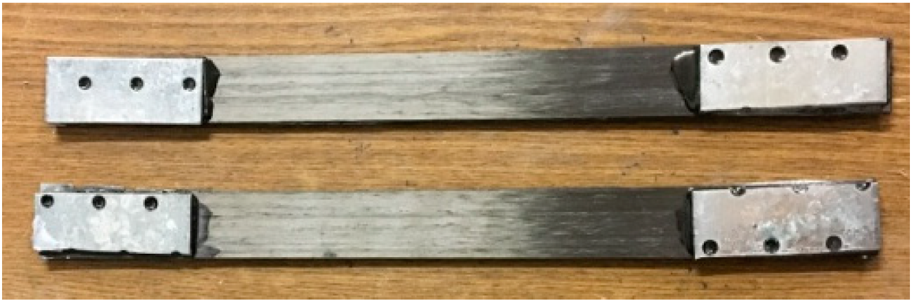
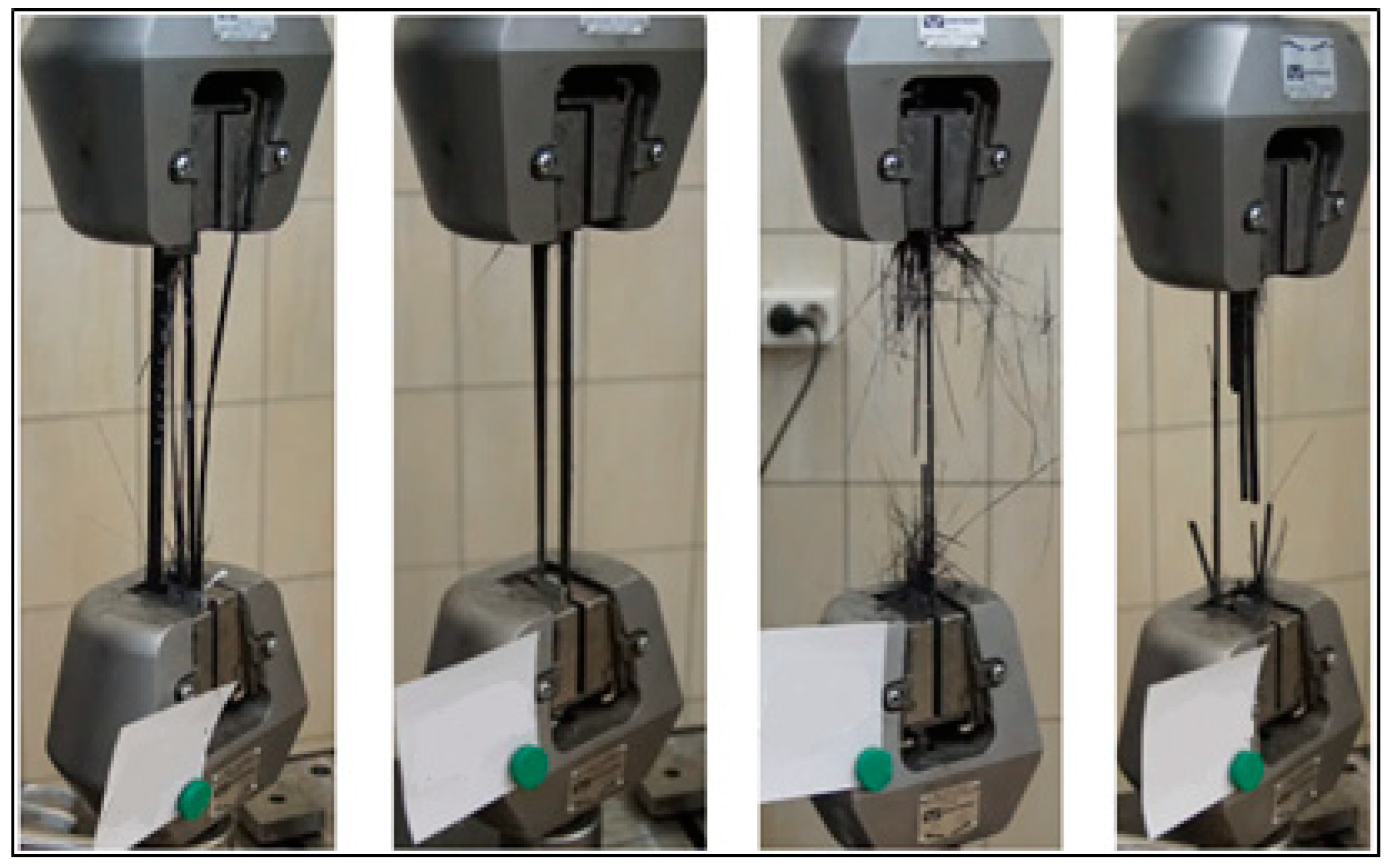
Before studying the strengthening of steel rods, the strength and rigidity of the lamellas were evaluated. For this purpose, six 25 mm wide specimens of lamellas were tensile tested (Figure 1).
Two steel plates were bonded to the ends of the specimens to prevent damage or slippage in the clamps of the testing machine. The velocity of clamps under tension varied from 0.5 to 1 mm/s, and all specimens were brought to failure in the process of testing.
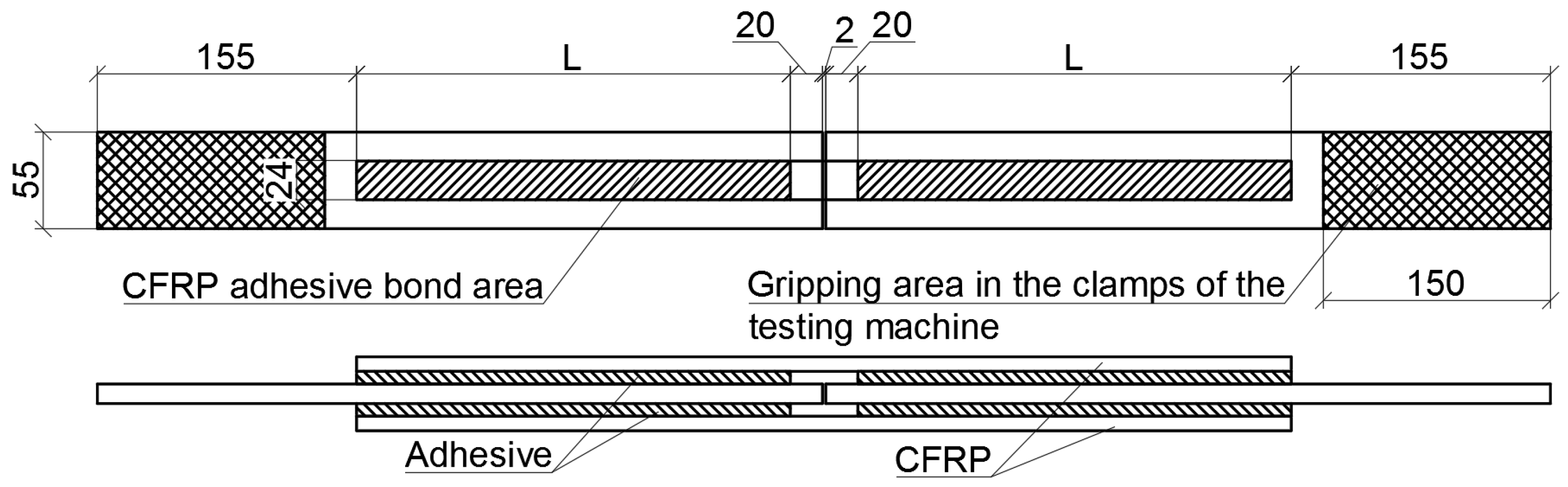
As a result of the experiment, the authors identified the length of the adhesive joint, that ensured the consolidated strength performance of lamellas and the steel rod without debonding. Special specimens (Figure 2) were applied to test the strength of the adhesive bond.
The specimens were two 12 mm thick, 55 mm wide steel plates made of S245 steel. There was a 2 mm gap between the plates, and CFRP lamellas were bonded to them on both sides. Each specimen had a unique length of adhesive bond l. In total, eight adhesive bond strength tests were conducted for four adhesive bond length values of 170, 200, 280, 310 mm. If the length of the adhesive bond area was minimal, adhesive bond strength was to withstand normal stresses in the lamellas reaching 2125 MPa. As for other lengths of the adhesive bond, lamellas, rather than adhesive layers, were to fail. Strength tests of the adhesive bond were used to identify normal stresses arising in a lamella to trigger the failure of the adhesive layer. Notations and parameters, used in the course of adhesive strength testing, are shown in Table 1.
In Table 1, the sample type is indicated by two numbers—the first number is the length of the CFRP, the second number is the sample number.
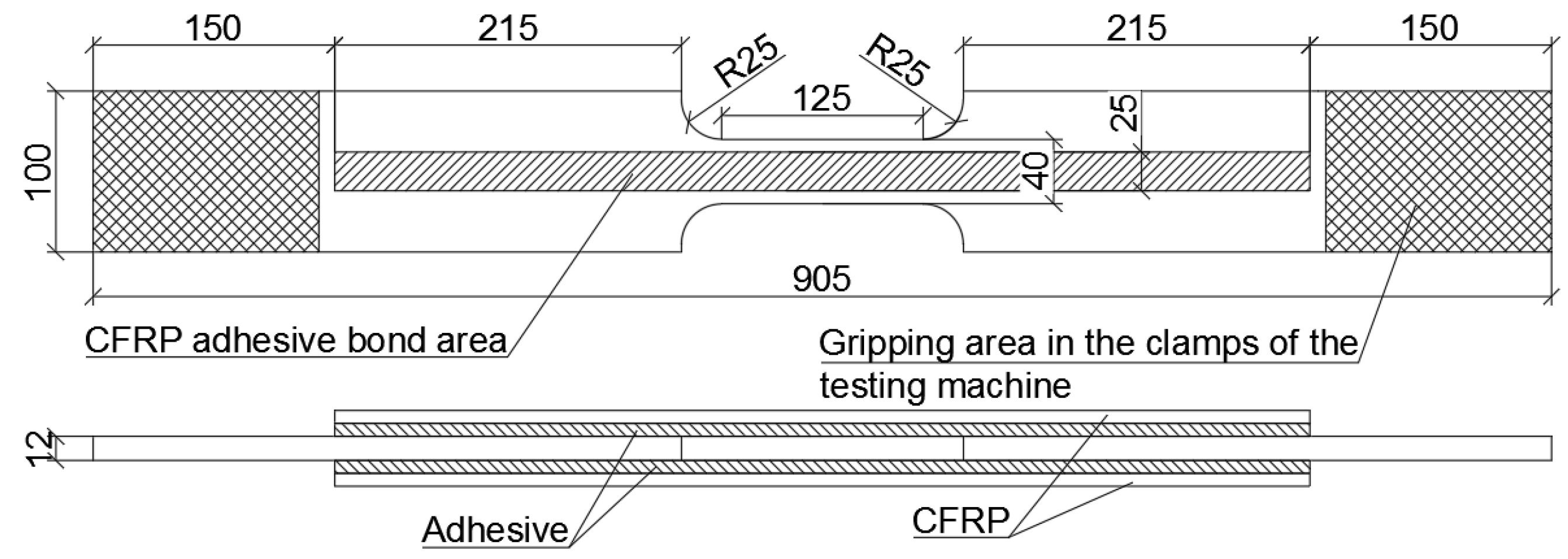
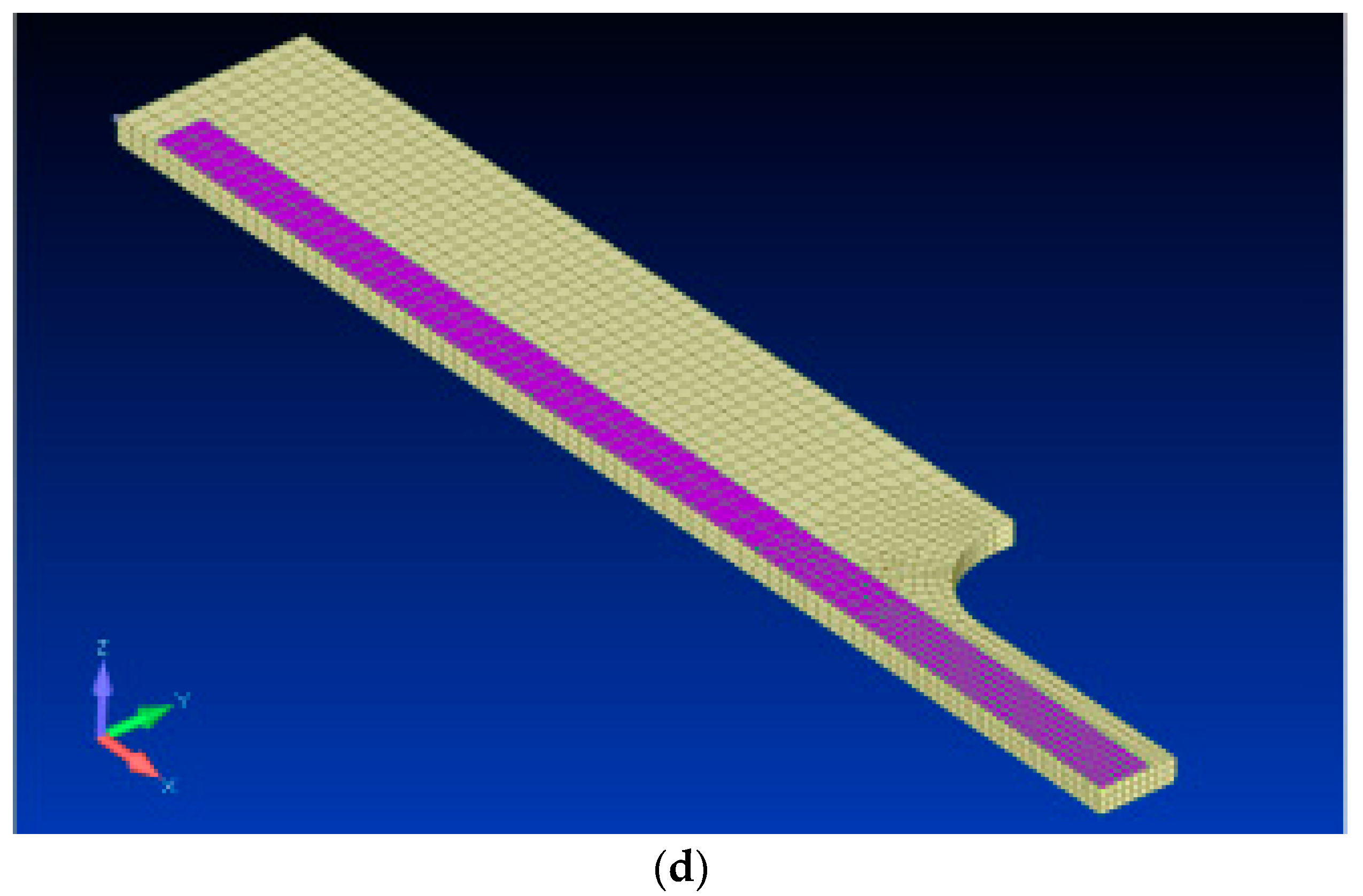
The next stage of experimental studies was the tensile testing of parameters, used in the course of adhesive strength testing of specimens, that were made of sheet steel and had an intricate shape (Figure 3).
The shape of the specimen was intricate in order to make its midsection fail. CFRP was bonded to the steel element along the entire length of a CFRP strip that extended beyond the less strong area, so that the strengths of these areas could ensure the strength of the adhesive joint when ultimate stresses arose in the lamella. It was assumed that the adhesive bond of lamellas along the entire length would make it possible to take maximal advantage of the CFRP strength. The cross-sectional area of the less strong part of the steel specimen was 4.8 cm2; the total area of the CFRP lamellas was 0.6 cm2; the length of the CFRP lamella was 605 mm. CFRP lamellas were bonded using two-component adhesive FibArm Resin Laminate+. Then, four specimens were tensile tested.
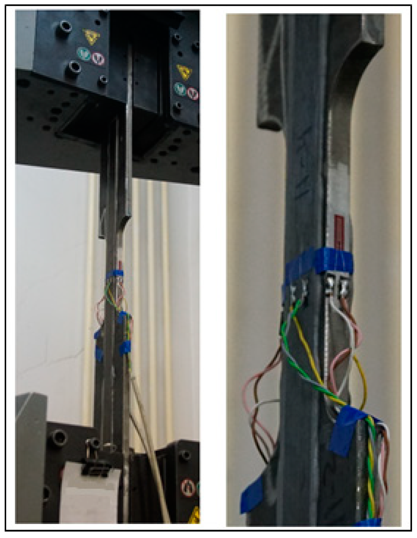
Specimen clamping areas were free of lamellas to prevent the CFPR damage when the specimen was subjected to loading. The specimens were clamped by the jaws of the testing machine so that the axes of the specimen and the testing machine coincided. In the course of testing, clamps of the testing machine moved at a speed of 2 mm/s, and the tensile force was registered by the sensors. In addition, strain gauges were attached to the two specimens to measure strain more accurately. Two sensors were mounted on the lamellas of one specimen along its axis. The same sensors were mounted on the lamellas of the other specimen, and two additional sensors were mounted on the side faces of the steel specimen.
To clarify the parameters before the testing of strengthened specimens, non-strengthened specimens were tested to determine the mechanical characteristics of steel specimens and identify the effect of strengthening on the bearing capacity. The general view of tested specimens is shown in Figure 4.
2.2. Theoretical Evaluation of Strength of a Strengthened Tensile Element
The following assumptions precede the theoretical evaluation of strength of a CFRP-strengthened tensile steel element:
- −
- Strain values of steel and CFRP coincide due to the small thickness of the adhesive layer before the failure of the adhesive joint;
- −
- The modulus of elasticity of CFRP before failure is close to the modulus of elasticity of steel ;
- −
- The value of normal stresses in CFRP does not exceed experimental values of in CFRP, determined by the strength of the adhesive bond;
- −
- To take into account the thicknesses of the CFRP, the coefficient of operating conditions is used, where is the thickness of lamellas in mm, the coefficient of working conditions takes into account that the limiting stresses in carbon fiber of a different thickness will differ from those experimentally determined for a 1.2 mm thick lamella, this coefficient allows you to convert experimental limiting stresses into limiting stresses in carbon fiber of a different thickness than in experiments.
The final two conditions mean that no strengthening is effective for CFRP, when stresses reach the value of . In case of such stresses, the adhesive bonding, used to fix the strengthening element to the steel profile, is destroyed and strengthening becomes ineffective. The longitudinal relative strain, corresponding to the failure of the adhesive layer, is
The strength of the adhesive joint is affected by both longitudinal and transverse deformations in carbon fiber and steel. This is important when analyzing the mechanism of the destruction of glue. When studying the load-bearing capacity of a CFRP-reinforced stretched steel element, the mechanism of glue destruction was not studied due to the recommendations of the carbon fiber manufacturer on the use of an adhesive joint performed using the glue and bonding technology recommended by the carbon fiber manufacturer. This made it possible to ensure the standard quality and strength of the adhesive joint. Tests of the adhesive joint showed its high strength, sufficient for practical use when reinforcing steel elements with carbon fiber and confirmed the validity of the manufacturer’s recommendations on the choice of glue and the technology of the connection. It has been experimentally established that, in this case, the normal stresses in carbon fiber cannot exceed a certain value, the achievement of a longitudinal force corresponding to these stresses in CFPR leads to the destruction of the adhesive and the exhaustion of the strength of the reinforced element. Thus, it is the longitudinal deformations and forces that are important for assessing the bearing capacity of a stretched element.
When a strengthened steel element stretches, several stages of its behaviour can be observed.
At the first stage, characterized by the elastic steel behaviour, normal stresses in steel and CFRP are approximately equal due to the close values of the modulus of elasticity of both materials. At the first stage, stresses , arising in steel, do not exceed the yield strength equal to .
At the second stage, stresses, arising in the steel rod, reach the yield strength of steel . As the load, applied to the rod, increases, and same about the strain, stresses change little in steel. Normal stresses in CFRP continue to grow in proportion to the modulus of elasticity up to the value equal to . When stresses reach , the adhesive layer fails and the same about the entire rod.
When the strengthened rod stretches, the stress-strain state of CFRP changes as follows:
- -
- At the first stage, strains and stresses are distributed along CFRP same as in the steel specimen;
- -
- At the second stage, stresses rise sharply in CFRP in the area of plastic strains, arising in the steel specimen;
- -
- The brittle failure of the adhesive strengthening layer is observed when stresses are reached in CFRP.
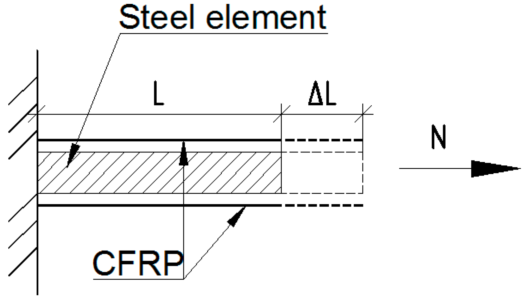
Let us make a theoretical analysis of the ultimate load that a tensile steel rod, symmetrically strengthened by CFRP, can resist. One end of the rod was rigidly fixed; the other free end was subjected to the longitudinal force (Figure 5).
The following notations are used: is the initial length of the rod, is the elongation of the rod in tension.
Let us assume that strains in the adhesive layer are negligibly small; in this case strains in steel and CFRP were the same before the failure of the adhesive. We also disregarded a change in the cross-sectional area of the steel specimen after it reached the yield strength point.
At the loaded end, the total force in steel and carbon fiber was equal to the load applied to the rod. The movements of the steel rod and carbon fiber at the loaded end of the rod were equal.
The total longitudinal force is the sum of longitudinal forces in the steel rod and CFRP:
where is the total longitudinal force resisted by the rod, is the longitudinal force resisted by the steel part of the rod, is the longitudinal force resisted by CFRP.
It follows from the equality of displacements of the steel part of the rod and CFRP that:
where is the length of the rod, is the cross-sectional area of steel, is the area of CFRP.
Based on (3), longitudinal forces and can be expressed as follows:
Having made several transformations, we obtained:
where ,
Then formula (2) could be written as follows:
When making calculations using formula (8), we assumed that strains in the rod were determined by strains in CFRP. The presence of the yield plateau of steel was not taken into account here. It was assumed that stresses rose in steel up to its failure at the initial modulus of elasticity of steel. This behaviour pattern generated an excessively high value of the bearing capacity.
Formula (9) assumes that the strength of the strengthened rod is exhausted when stresses, arising in steel, reach the yield point. In this case, stresses in CFRP did not reach the limit value, and the longitudinal force value turned out to be underestimated.
The development of plastic strains was acceptable in steels whose yield point did not exceed 440 MPa; therefore, the bearing capacity of CFPR-reinforced steel rods was determined taking into account the behaviour of steel in the plastic range. Only when plastic strains developed in steel could limit stresses arise in CFPR and the adhesive layer could fail.
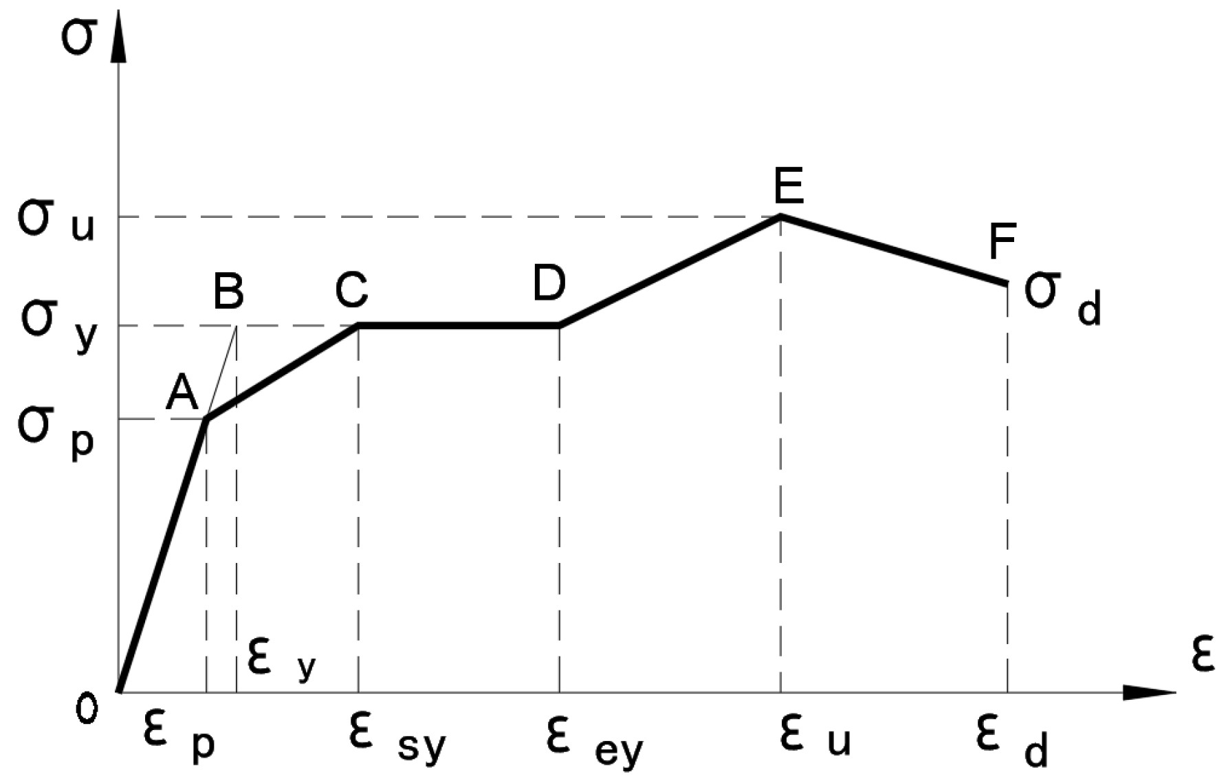
To clarify the value of the bearing capacity taking into account the development of plastic strains in steel, we used the following diagram of the steel behaviour (see Figure 6).
In the diagram, is the proportional limit, is the yield point, is the strength limit, is stress at the moment of the specimen rupture, is the relative strain of the proportional limit, is the relative strain of the yield point, is the relative strain of the beginning of the yield plateau, is the relative strain of the end of the yield plateau, is the relative strain of the strength limit, is the relative strain of the specimen rupture. The letters A-F indicate the characteristic fracture points on the graph.
Let us identify the bearing capacity of a steel rod strengthened by CFRP taking into account the above diagram.
Strains corresponding to the yield point are equal to:
Parameters of the diagram depend on the yield point and are as follows:
- −
- for steels with the yield point below 355 MPa:
- −
- for steels with the yield point from 355 MPa to 440 MPa:
Let us assume that after reaching the proportional limit, the modulus of elasticity of steel is constant and it is determined by the diagram of the steel behaviour in the AC section of Figure 6:
Hence,
- −
- for steels with the yield point below 355 MPa:
- −
- for steels with the yield point from 355 MPa to 440 MPa:
Therefore, formula (1) can be represented as follows:
where is the portion of longitudinal force, arising in the steel rod and resisted before the proportional limit is reached; is the portion of longitudinal force resisted if the proportional limit is exceeded, is the longitudinal force resisted by CFRP.
Let us suppose that the ultimate elongation of the rod is determined by the ultimate stresses in CFRP. In this case, strains will be calculated as follows:
Then the bearing capacity of the strengthened rod will be calculated as follows:
- −
- for steels with the yield point below 355 MPa:
Or:
- −
- for steels with the yield point from 355 MPa to 440 MPa:
Or:
Formulas (19) and (20) obtained using the normative diagram of steel work (Figure 6) could be applied to make a theoretical evaluation of the strength of a tensile steel rod, strengthened by CFRP.
2.3. Numerical Studies
The analysis of CFRP-strengthened tensile steel rods was performed using the finite element method and the Nasnran software.
The computational model of a strengthened tensile steel element was developed using 3D elements of the solid type, which had the shape of an 8-node hexahedron. Nodes of finite elements were united at the interface between different materials (steel-adhesive, adhesive-lamella).
Interaction between a steel rod and strengthening elements was simulated by adding finite elements of the adhesive layer to the computational model. The characteristics of this layer were clarified as a result of successive computations of models, having parameters of the adhesive, and the outcomes of computations were compared with the experimental data obtained in the course of studying the strength of the adhesive bond between CFRP and the steel rod. This approach enabled the authors to set the parameters of the material that simulated the adhesive layer, so that the computation results corresponded to the test data. In the second case, the adhesive was not included in the computational model, and it was taken into account due to the fact that CFRP had a strength of 686 MPa in the finite–element model. This value corresponded to stresses in the lamella that caused the adhesive layer to fail during the experiment. When these stress values were attained, CFRP stopped resisting any loads, which were thereafter resisted by steel only.
The material was assumed to be isotropic in the finite–element model. Its properties were the same in all directions. Characteristics of the isotropic material were set using the following basic parameters: Young modulus, Poisson’s ratio, and the limit stress of the material. The value of the shear modulus was calculated using the following formula:
where is the modulus of elasticity, MPa; is the Poisson’s ratio.
To take into account the physical nonlinearity of the system, functional dependences between stresses () and strains () were set. They described the relationship between strains and stresses. A general model of an elastic–plastic material, called Plastic, was used. The properties of this nonlinear material include the stress–strain curve, the Yield Criterion, the Yield Stress, and the Hardening Rule.
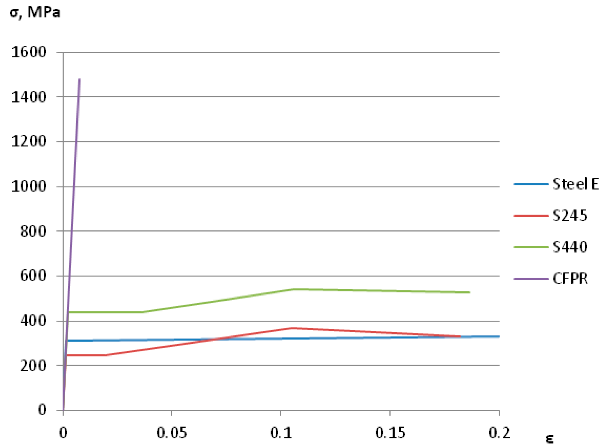
Initially, the modulus of elasticity of steel was constant, and the stress–strain relationship was linear. After the yield point was reached, two options of the steel behaviour diagram were used. For the steel, used in the experiments (SteelE), a bilinear diagram was used. For S245 and S440 steels, the generalized steel diagram was used (Figure 6). Parameters of the generalized diagram, made for steels S245 and S440, are listed in Table 2.
The CFRP lamella had an elastic modulus of 190,000 MPa at normal stresses not exceeding 1480 MPa, a shear modulus of 79,166 MPa. The steel had an elastic modulus of 206,000 MPa, a shear modulus of 79,230 MPa. The adhesive had a modulus of elasticity of 200,000 MPa, a shear modulus of 76,923 MPa.
Figure 7 shows the dependence between the stresses and strains for the materials of a strengthened steel element.
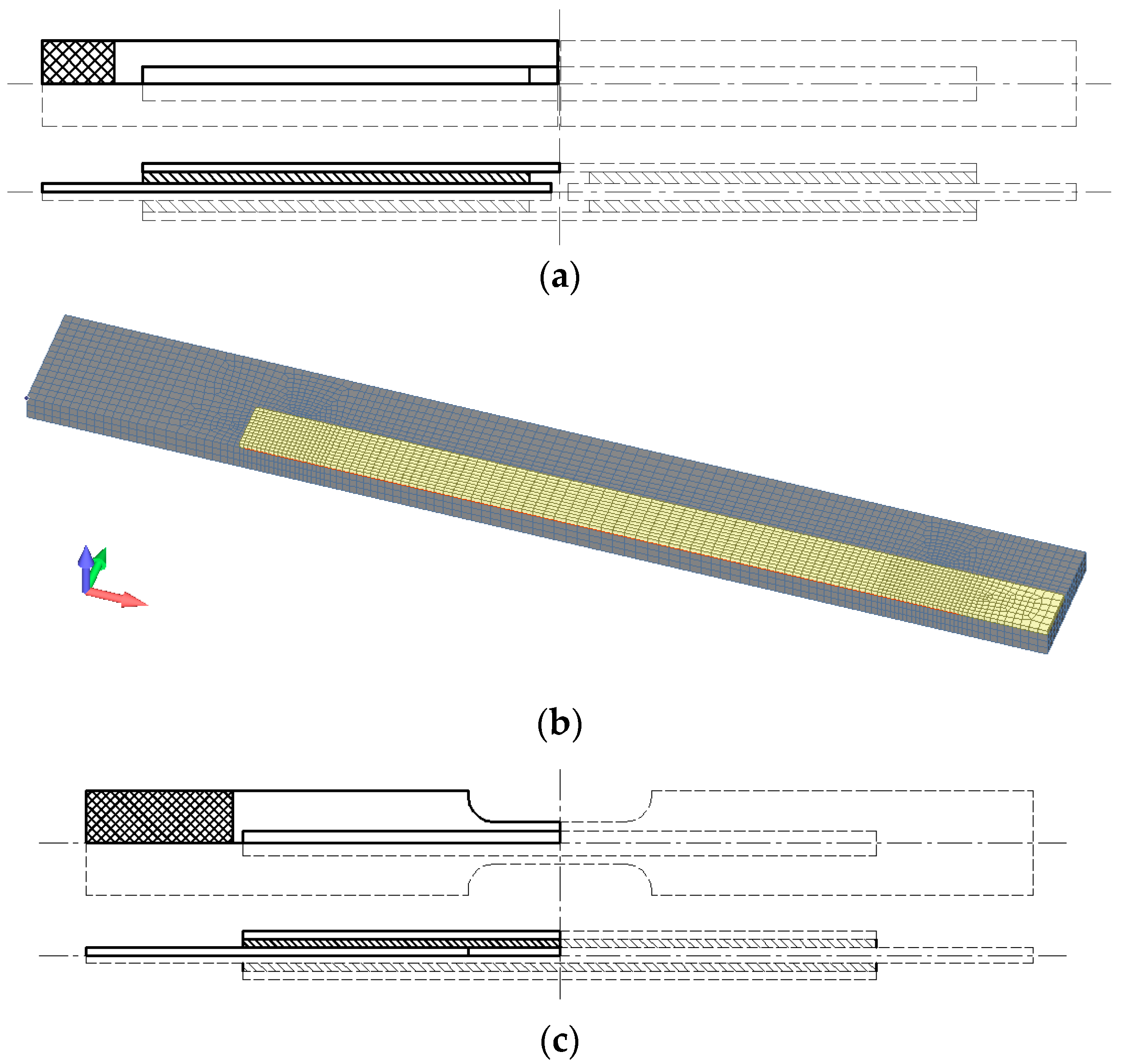
Numerical studies were made for two finite-element models. The first one simulated the experimental specimens, used to evaluate the strength of the adhesive joint (Figure 2). The second one was used to analyze the CFPR-strengthened steel element (Figure 3). To reduce the calculation time, 1/8th of the experimental specimen was used in the computational model, given the symmetry of the specimen. Figure 8 shows parts of experimental specimens, used in the calculation, as well as their FEM models.
The longitudinal force in the specimens was set by displacing one of the ends of the computational model, while the other end remained still. The calculation was performed using the extended nonlinear transient solver of the Nastran software, that was titled “23...Advanced Nonlinear Transient”. It takes into account geometrical and physical nonlinearities.
When the adhesive was added to the finite-element models, its strain and strength characteristics were selected so that the numerical results corresponded to the data obtained during the experimental studies of the adhesive layer and its strength.
Two options of adding the adhesive to the finite-element models were considered:
- −
- The first option: the adhesive layer consisted of one row of finite elements with a thickness of 0.1 mm;
- −
- The second option: the adhesive layer had two rows of finite elements with a total thickness of 0.4 mm.
The cross-sections of elements in the computational model were as follows: steel plate—27.5 × 6 mm; two CFPR lamellas—12.5 × 1.2 mm. The length and width of all finite elements were 2 to 5 mm. In terms of thickness, the steel element was divided into six rows of elements; the CFPR lamella was simulated by one row. The mesh, selected to split the specimen into finite elements, was checked during the tensile test calculations of steel rods, which confirmed the reliability of numerical results and acceptable computing time.
3. Results
3.1. Results of Experimental Studies
The strength and the modulus of elasticity of CFPR were identified as a result of the tensile testing of the lamella specimens. Figure 9 shows specimens after testing.
Table 3 shows the results of tensile testing of the lamella specimens.
In the course of tensile testing, it was found that initial signs of failure of individual CFPR fibers appeared in the case of stresses whose values were, on average, twice as small as the maximum stresses arising in the specimen. It was found that, at voltages not exceeding 760 MPa, the “strain–stress” relationship was linear, and the modulus of elasticity was 202,000 MPa. When the stress values were at maximum, the average modulus of elasticity of the lamella was 170,000 MPa.
The discrepancies in the test results were due to the variation of the properties of carbon fiber. During further calculations, the average indicators of carbon fiber were determined, which were used in the methodology for determining the bearing capacity of a steel stretched element reinforced with carbon fiber.
By testing different lengths of the adhesive joint of specimens, the authors identified the load of failure and the dependence between the movements of testing machine’s clamps and loading. Table 4 shows testing results in respect of the strength of the adhesive joint.
All specimens failed along the adhesive layer when the load value was close to that of stress in the lamellas. The average stress, at which the adhesive joint failed, was 685.8 MPa. It was found, experimentally, that no similar increase in the strength of the adhesive joint was observed when the length of the adhesive joint was increased in specimens 435, 595, 660 by 18, 65, 82%, respectively. The departure of ultimate stresses from the average value did not exceed 8%. Stresses, arising in the CFPR lamellas in case of failure, reached mere 28–32% of the CFPR strength. Hence, the adhesive joint made using the two-component epoxy adhesive FibArm Resin Laminate+ allowed for normal stresses, equal to 685.8 MPa, to arise in the 1.2 mm-thick CFPR lamella “FibArm Lamella-12/50. However, failure stresses did not exceed the ultimate stress in the CFPR lamella (760 MPa), at which it behaved linearly with the modulus of elasticity which was close to the modulus of elasticity of steel.
The elongation of specimens showed that, although the bearing capacity of tested specimens was almost the same, their strain properties were different. It was, experimentally, found that, the greater the length of the adhesive joint, the more rigid the structure. Thus, specimens 380-1 and 380-2 had an average strain of 0.53%, specimens 435-1 and 435-2—0.50%, specimens 595-1 and 595-2—0.40%, specimens 660-1 and 660-2—0.26%.
Thus, it has been experimentally established that the strength of the adhesive joint does not depend much on the length. This is due to the uneven distribution of stresses in the glue. It is known that in connections parallel to the acting force, maximum stresses occur at the beginning of the connection. Therefore, the destruction begins at the beginning of the adhesive joint when certain stresses are reached in the carbon fiber, and then the destruction will spread along the layer.
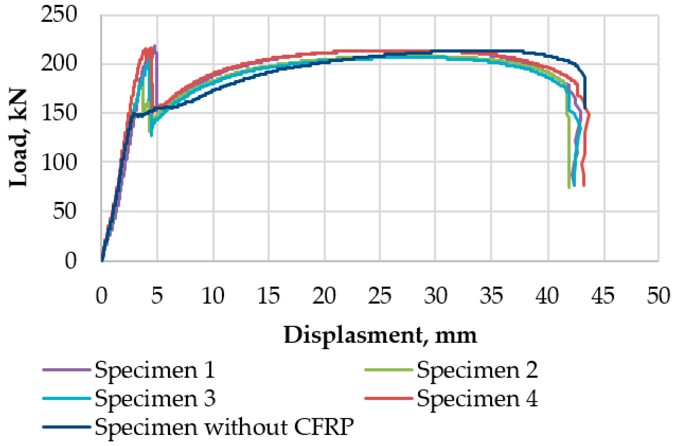
The testing of strengthened specimens showed a noticeable increase in the bearing capacity due to a rise in the bearing capacity of the CFPR elements. Figure 10 shows the displacement-load dependencies obtained as a result of testing the strengthened specimens. For comparison purposes, the displacement-load relationship was also provided for the specimen that had no strengthening.
The analysis of the experimental data shows that all strengthened specimens demonstrated linear behaviour, if the load was below 170 kN. Here, the steel behaviour pattern was elastic in a strengthened specimen. The linear strain, arising in strengthened specimens, coincided with the linear portion of the steel behaviour diagram. The specimen that had no strengthening demonstrated linearity at a load of 150.0 kN, and if the load exceeded this value, plastic strain developed in steel specimens. Plastic strain developed in the steel of reinforced specimens at a load of about 170 kN due to the fact that CFPR lamellas resisted part of the longitudinal force value. The value of the longitudinal force, resisted by CFPR lamellas if the modulus of elasticity of lamellas was close to the modulus of elasticity of steel, which was true if the stress in lamellas was below 760 MPa, could be determined by distributing the experimental load in proportion to the areas of carbon fiber composite lamellas and the steel rod. Then, the longitudinal force in CFPR lamellas were 150.0*0.6/4.8 = 18.8 kN during the development of plastic strains in steel, and the total longitudinal force was 168.8 kN, which was close to that observed in the course of the experiment.
The value of tensile load kept going up until the adhesive joint failed in all specimens. At the moment of failure, the specimen loading went down, since after the failure of the strengthening element, the load was resisted by the steel rod only, and in the plastic stage its bearing capacity was equal to approximately 150.0 kN. In the course of further loading, the behaviour of the specimen was similar to the diagram of the steel behaviour. The self-strengthening stage of steel followed the yield plateau. Self-strengthening was accompanied by a rapid growth of strains, and the specimen failed, if the load value ranged from 206 to 213 kN, which corresponded to stresses arising in steel that were equal to 381.4 and 394.4 MPa, respectively.
Table 5 shows the loads of failure, that cause the strengthening element to fail, and stresses in the CFPR lamellas.
The post-strengthening increase in the bearing capacity ranged from 27 to 50%. The average value of the bearing capacity increased was 38%. It should be noted that the effective inclusion of carbon fiber in joint work with a steel element was possible only with the development of plastic deformations in steel.
3.2. Results of Theoretical and Numerical Studies
Calculations of the bearing capacity of strengthened specimens, made using analytical dependencies (5) and (6), are presented in Table 6.
The calculation made according to formulas (5) and (6) confirmed an increase in the bearing capacity of strengthened steel rods, which was 60% and 17% for steels S245 and S440, respectively. An increase in the bearing capacity of steel with the yield limit of 312.5 MPa was 39%. The analytical bearing capacity differs from the experimental results by no more than 1%.
When numerical studies were conducted, two models of adhesive bonds were considered, the first one had one layer, and the second one had two layers. To obtain correct numerical results, adhesive parameters were chosen so that the numerical results correlated well with the experimental data. Table 7 presents characteristics of the adhesive layer, used in the finite-element models of the analyzed elements. These models take into account the interaction between CFPR and a steel specimen when the adhesive joint is taken into account in the calculations.
Numerical studies of the strength of an adhesive joint showed non-uniform distribution of stresses along the length of the adhesive layer and CFRP. Maximum shear stresses arose in the adhesive, and normal stresses arose in the initial zone of the steel-reinforcement joint.
Figure 11 shows the distribution of stresses in the adhesive layer before the failure.
Calculations have revealed that the greatest stresses arose in the boundary zone of the adhesive layer due to its small thickness, while all other parts of the joint remained “underloaded”. A wider zone of the adhesive joint can resist a load if the modulus of elasticity of the adhesive is reduced. However, in this case the deformability of the joint increased significantly and numerical displacements, corresponding to the joint failure, were much higher than the experimental ones.
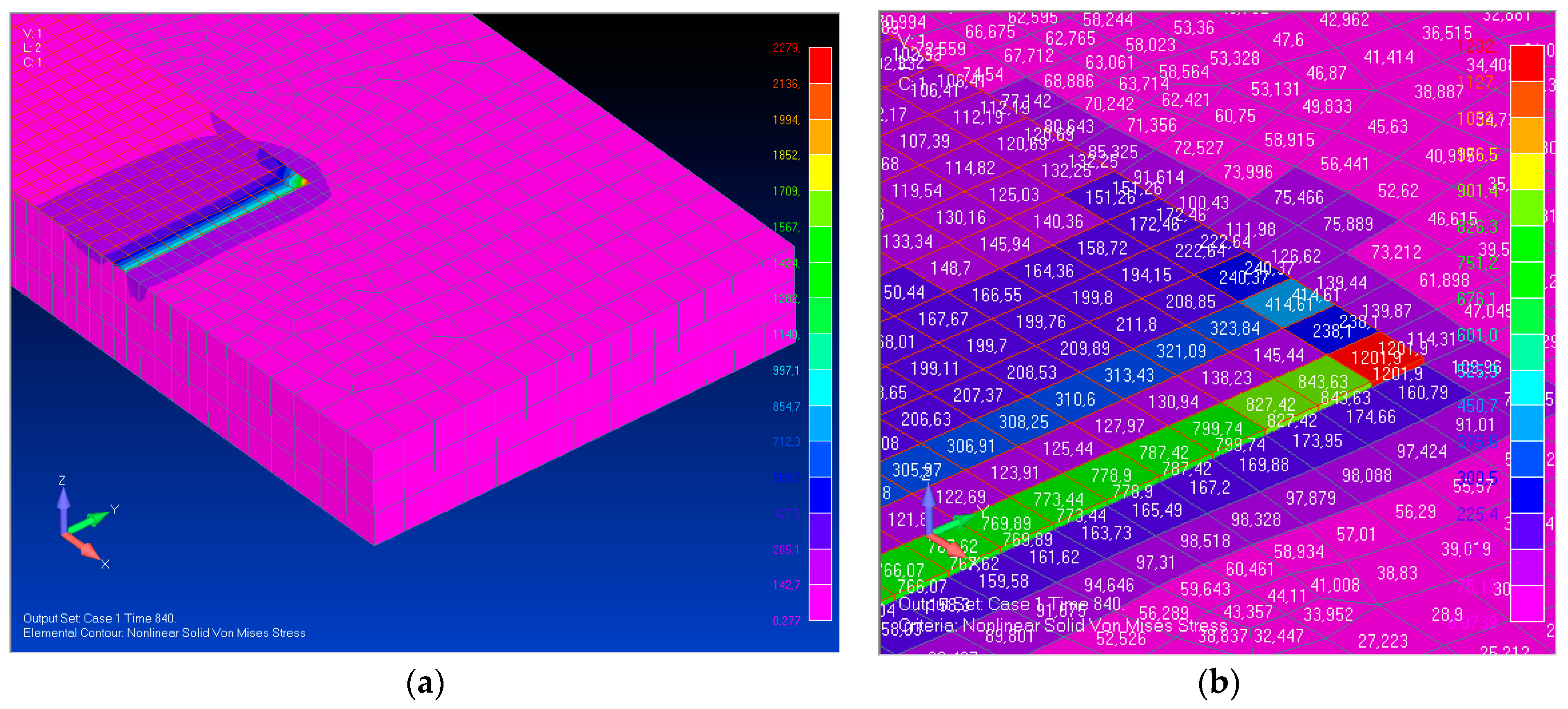
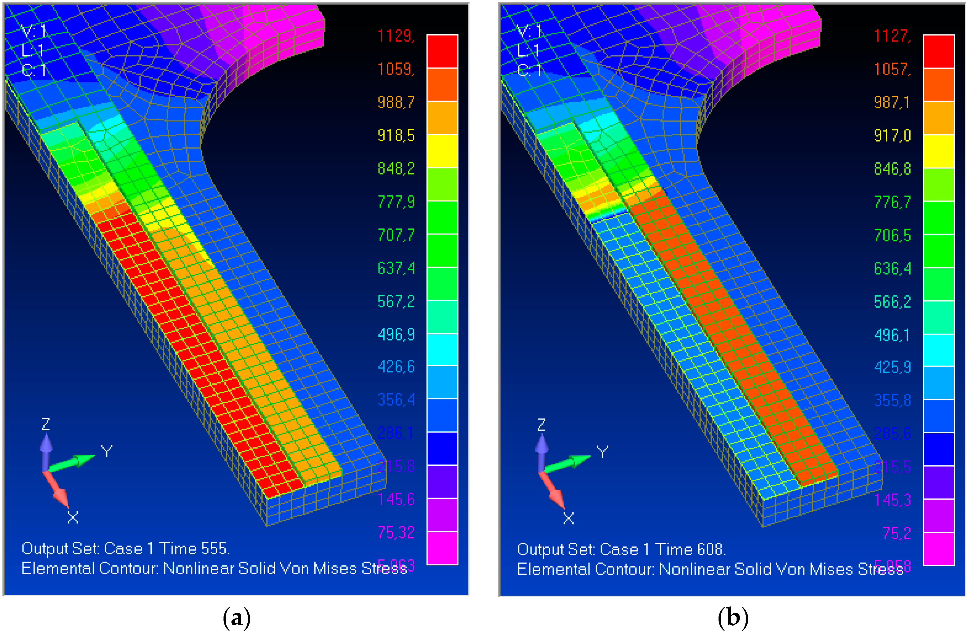
Numerical calculations of the strengthened element were performed after selecting the parameters of the adhesive layer. Figure 12 shows stresses in the strengthened specimen. CFPR is not shown in the figure in full to better visualize the results.
Before the failure of the adhesive layer, stresses equal to 312.4 MPa were observed in steel and 951.3 MPa in CFRP. After the failure of the adhesive layer, stresses in steel and CFPR were 313.8 and 1043.1 MPa, respectively.
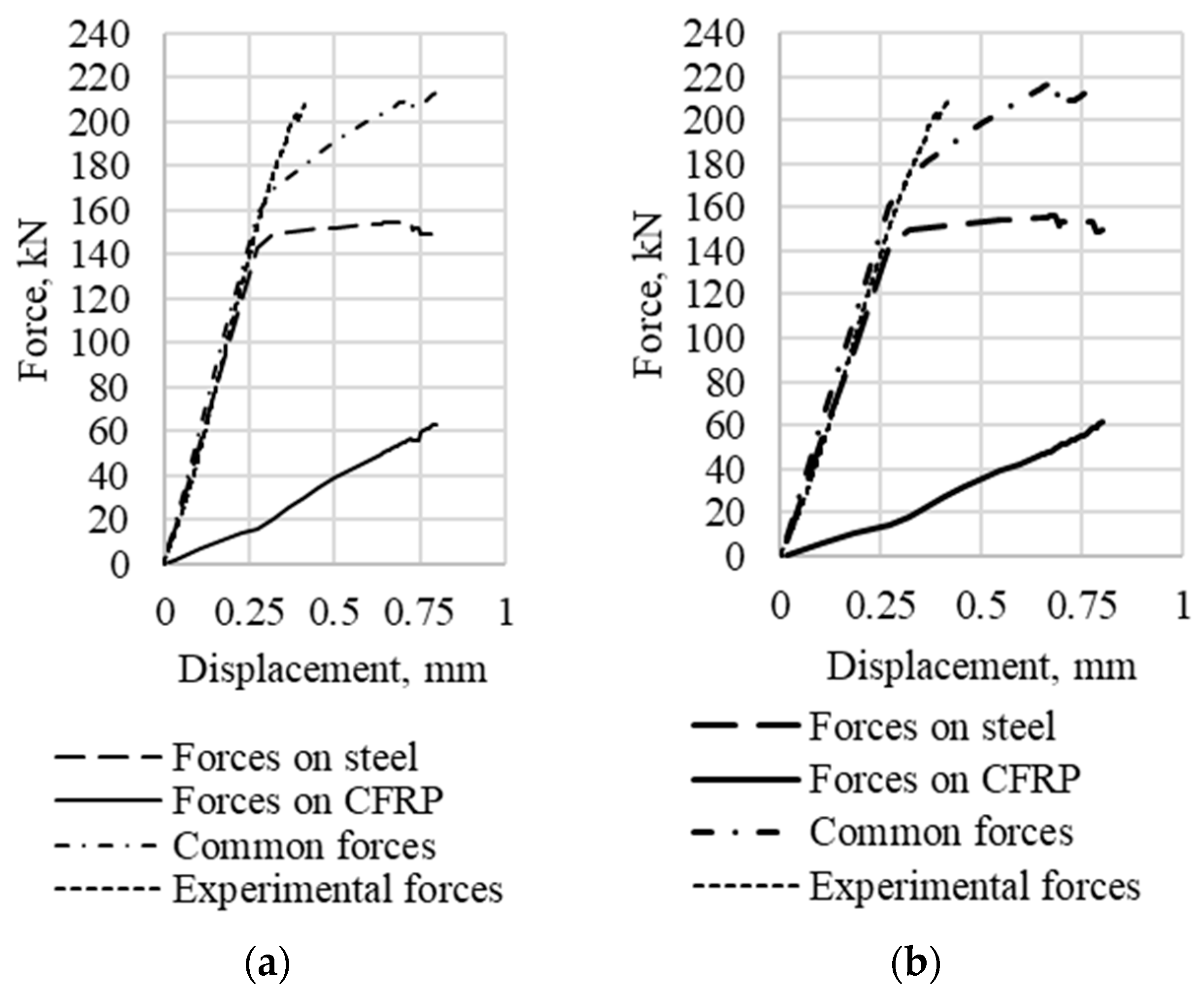
Longitudinal forces resisted by individual elements in the midpart of the strengthened specimen were identified using the results of the numerical calculation. Figure 13 shows the relationship between the longitudinal force and the displacement of the wide end for different options of the simulated adhesive layer
Calculation results obtained for different adhesive layer simulation options are presented in Table 8.
According to the calculation results, models with one and two layers of the adhesive had very close values of the bearing capacity of the strengthened specimen, the discrepancy was about 0.8%. A good coincidence of the load-bearing capacity obtained as a result of numerical calculations with experimental data has been established—the difference was no more than 3%. It should be noted that, according to the calculation, the destruction of the reinforced element was accompanied by movements that turned out to be 2 times larger than the experimental ones. The reason for the greater calculated deformability is that in the finite element model it was not possible to accurately simulate the experimentally established brittle nature of the destruction of the adhesive after reaching the limiting stresses in carbon fiber.
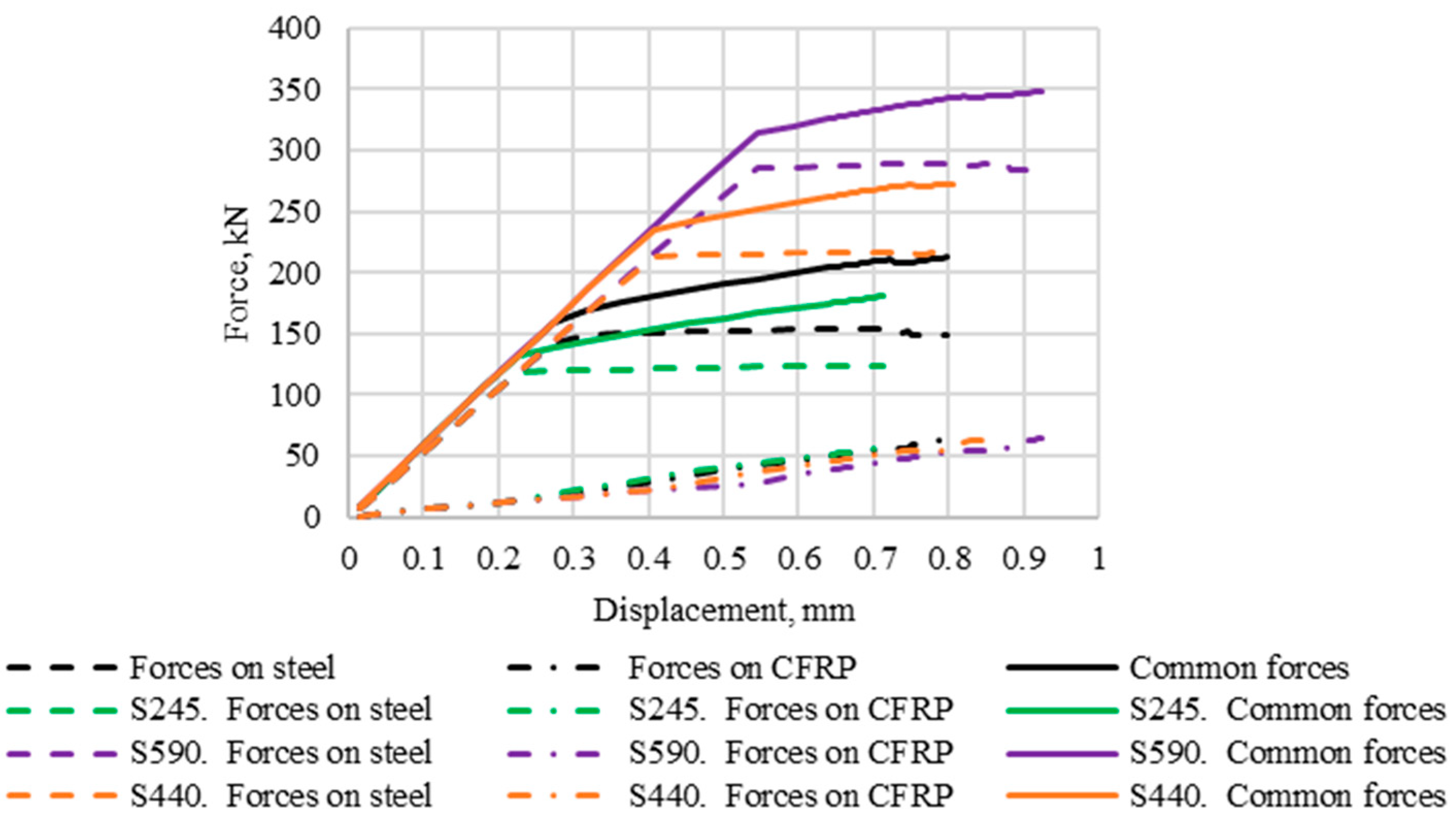
Calculations were made using S245 and S440 steels as experimental specimen materials. Since the influence of the number of rows of finite elements in the adhesive layer had little effect on the calculation results, strengthened tensile specimens of steel S245 and S440 were analyzed by using one row of finite elements to simulate the adhesive layer. Figure 14 shows the displacement-force relationship obtained using the FEM method of analysis of strengthened tensile rods made of different steels.
Calculation results are presented in Table 9 for strengthened steel specimens made of steel S245 and S440.
4. Discussion
The tensile testing of CFPR lamella specimens has proven their high strength, which is several times higher than the strength of steel. The modulus of elasticity of lamellas is 170,000 MPa, which is slightly smaller than that of steel. The modulus of elasticity of lamellas in the stress range of 0 to 760 MPa is only 2% smaller than that of steel. Hence, when stresses are sufficiently high, the value of the modulus of elasticity of lamellas is almost equal to that of steel.
Experimental studies of the adhesive joint have identified the joint strength performance of a steel element and a CFPR lamella. It has been found that the length of an adhesive joint must be equal to or greater than a certain value to ensure the effective joint strength performance of a CFPR lamella and a steel element. Any longer adhesive joint does not lead to any noticeable rise in lamella stresses and, hence, to any growth in the bearing capacity of a strengthened element.
Numerical studies identified the reason for such behaviour of an adhesive joint. The failure of the adhesive commences in the initial zone of the joint, where conditions are created for the adhesive strength to be exhausted in the lamella if the stress value is the same. Later, the zone of the adhesive failure expands while the stress level does not change in the lamellas. It has been experimentally proven that the strength of the adhesive joint makes it impossible to take full advantage of the strength of lamellas that are 1.2 mm thick. In spite of this, the stress level, developed by CFPR due to the strength of the adhesive layer, is several times higher than the strength of steel.
Values of stresses in CFPR, identified in the course of the experiment and achievable for any length of the adhesive, cause the adhesive joint layer to fail. They are recommended for use in the practical calculations of the bearing capacity of CFPR-strengthened steel rods.
A major increase in the bearing capacity of CFPR-reinforced tensile steel rods is experimentally identified. The strength performance of CFRP reinforcement is effective when the behaviour of steel is plastic. An increase in the bearing capacity is confirmed by numerical calculations. A calculation methodology has been developed to evaluate the strength of reinforced steel tensile rods. Experimental results, data of numerical calculations, and calculations made using the methodology, developed by the authors, showed good convergence. The value of the ultimate load of a CFPR-strengthened tensile steel rod, determined by different methods, was, kN:
- −
- Experiment: 205.0;
- −
- Numerical calculations: 210.7;
- −
- Calculation methodology: 208.9.
The discrepancy between the results, obtained by different methods, did not exceed 3%.
According to the results of the research, the conclusion is made about the feasibility of a substantial increase in the bearing capacity of tensile steel rods thanks to CFRP. It is impossible to take maximum advantage of the strength properties of CFRP fixed it to steel using adhesive bonding. To ensure more effective strength performance of CFRP, it is necessary to increase the strength of an adhesive joint and make sure that the values of stresses in CFRP are close to the limit ones. To form a normative methodology for calculating carbon reinforced stretched steel rods, it is necessary to conduct a complex of tests to determine the normative parameters of the bearing capacity of the adhesive joint and stresses in carbon fiber.
5. Conclusions
- The modulus of elasticity of carbon fiber lamellas is 17% smaller than the modulus of elasticity of steel.
- If stresses do not exceed 760 MPa, the modulus of elasticity of lamellas differs from the modulus of elasticity of steel by no more than 2%.
- To assess the bearing capacity of reinforced steel elements, it is necessary to identify the strength of the adhesive joint, which determines maximum stresses in CFRP.
- Effective joint strength performance of a steel element and CFPR occurs when plastic strains develop in steel.
- The analytical dependence was developed to determine the bearing capacity of a strengthened tensile steel element.
Author Contributions
Conceptualization,; methodology, A.T.; software, A.T. and E.S.; validation, E.S.; formal analysis, A.T.; investigation, A.T. and E.S.; resources, A.T. and E.S.; data curation E.S.; writing—original draft preparation, A.T. and E.S.; writing—review and editing, A.T.; visualization, E.S.; supervision, A.T.; project administration, A.T.; funding acquisition, A.T. All authors have read and agreed to the published version of the manuscript.
Funding
This research is funded by the grant issued by the National Research Moscow State University of Civil Engineering as a result of a competition among the lecturers for implementation of fundamental and applied scientific research (R&D) by the teams of NRU MGSU researchers. (Order 527/130-22/06/2022-project No. 1).
Data Availability Statement
The data presented in this study are available on request from the corresponding author.
Conflicts of Interest
The authors declare no conflict of interest.
References
- Batikha, M. Strengthening of Thin Metallic Cylindrical Shells Using Fiber Reinforced Polymers; Institute for Infrastructure & Environment, The School of Engineering and Electronics The University of Edinburgh: Edinburgh, UK, 2008; 149p. [Google Scholar]
- Teng, J.G.; Yu, T.; Fernando, D. Strengthening of steel structures with fiber-reinforced polymer composites. J. Constr. Steel Res. 2012, 78, 131–143. [Google Scholar] [CrossRef]
- Zhao, X.; Al-Mahaidi, R. Performance of CFRP strengthened lightsteel beams subjected to end bearing forces. Asia-Pac. Conf. FRP Struct. 2007, 6, 937–942. [Google Scholar]
- Mustafa, S.A.; Fathy, E.; Rizk, M.S. Rizk Adequate CFRP length for strengthening steel beams with web opening. In Proceedings of the 9th International conference on Nano-Technology in Construction, Sharm El-Sheikh, Egypt, 11–15 March 2017; pp. 1–12. [Google Scholar]
- Yu, Q.-Q.; Zhao, X.-L.; Al-Mahaidi, R.; Xiao, Z.-G.; Chen, T.; Gu, X.-L. Tests on Cracked Steel Plates with Different Damage Levels Strengthened by CFRP Laminates. Int. J. Struct. Stab. Dyn. 2014, 14, 1450018. [Google Scholar] [CrossRef]
- Yu, Q.; Zhao, X.; Al-Mahaidi, R.; Xiao, Z.; Chen, T.; Gu, X. Experimental study on repair of steel plate with different damage degrees subject to fatigue loading. In Proceedings of the 7th International Conference on Bridge Maintenance, Safety and Management (IABMAS), Shanghai, China, 7–11 July 2014. [Google Scholar]
- Narmashiri, K.; Jumaat, M.; Sulong, R. Shear strengthening of steel I-beams by using CFRP strips. Sci. Res. Essays 2010, 5, 2155–2168. [Google Scholar]
- Narmashiri, K.; Jumaat, M.; Sulong, R. Local Stiffening of Steel I-Beams by Using CFRP Materials. Adv. Mater. Res. 2011, 30, 1–9. [Google Scholar] [CrossRef]
- Narmashiri, K.; Jumaat, M.; Sulong, R. Failure analysis and structural behaviour of CFRP strengthened steel I-beams. Constr. Build. Mater. 2012, 30, 1–9. [Google Scholar] [CrossRef]
- Ochi, N.; Matsumura, M.; Hisabe, N. Experimental Study on Strengthening Effect of High Modulus CFRP Strips with Different Adhesive Length Installed onto the Lower Flange Plate of I Shaped Steel Girder. In Proceedings of the 12th East Asia-Pacific Conference on Structural Engineering and Construction (EASEC), Hong Kong, China, 26–28 January 2011; Volume 14. [Google Scholar]
- Lam, D.; Clark, K.A. Strengthening steel sections using carbon fiber reinforced polymers laminates. Adv. Struct. 2003, 1, 1369–1374. [Google Scholar]
- Ghareeb, M.; Khedr, M.; Sayed-Ahmed, E. CFRP strengthening of steel I-beam against local web buckling: A numerical analysis. In Proceedings of the 5th International Conference on Structural Engineering, Mechanics & Computation, Cape Town, South Africa, 2–4 September 2013; pp. 2421–2425. [Google Scholar]
- Lupasteanu, V.; Taranu, N.; Mihai, P.; Oprisan, G.; Lupasteanu, R. Comportarea Regiunii de Interfata Dintre Otel si Lamellaele Compozite Polimerice Armate cu Fiber de Carbon la Imbinarile Adezive. Rom. J. Mater. 2016, 46, 515–522. [Google Scholar]
- Danilov, A. CFRP Reinforcement adhesive joint performance on the transversely damaged steel elements under axial tension. MATEC Web Conf. 2017, 177, 00033. [Google Scholar] [CrossRef] [Green Version]
- Danilov, A.; Kalugin, I. Analytical and finite element modeling in the calculation and design of reinforcements of stretched elements by fiber-reinforced polymers based on high-strength fiber using adhesive joints. Struct. Mech. Eng. Constr. Build. 2018, 14, 414–426. [Google Scholar] [CrossRef]
- Danilov, A.; Kalugin, I. Cascade method of stretched elements strengthening by FRP. In Proceedings of the E3S Web of Conferences, 22nd International Scientific Conference on Construction the Formation of Living Environment, FORM 2019, Tashkent, Uzbekistan, 18–21 May 2019; p. 04037. [Google Scholar]
- Koller, R.; Stoecklin, I.; Valet, G.; Terrasi, G. CFRP-Strengthening and Long-Term Performance of Fatigue Critical Welds of a Steel Box Girder. Polymers 2014, 6, 443–463. [Google Scholar] [CrossRef] [Green Version]
- Aggelopoulos, E. Composite Patch Repair of Fatigue-Damaged Steel Members; University of Surrey: Guildford, UK, 2007; p. 144. [Google Scholar]
- Phan, H.; Jiao, H.; Holloway, D.; Taylo, C.; Zhao, X. The Behaviour of cfrp Strengthened Steel Joints; University of Tasmania: Hobart, Australia, 2015; p. 94. [Google Scholar]
- Keykha, A.H. A numerical investigation on the structural behavior of deficient steel frames strengthened using CFRP composite. Civ. Eng. Dimens. 2018, 20, 1–7. [Google Scholar] [CrossRef] [Green Version]
- Ghafoori, E.; Prinz, G.S.; Mayor, E.; Nussbaumer, A.; Motavalli, M.; Herwig, A.; Fontana, M. Finite Element Analysis for Fatigue Damage Reduction in Metallic Riveted Bridges Using Pre-Stressed CFRP Plates. Polymers 2014, 6, 1096–1118. [Google Scholar] [CrossRef] [Green Version]
- Ulger, T.; Okeil, A. Analysis of thin-walled steel beams retrofitted by bonding GFRP stiffeners: Numerical model and investigation of design parameters. Eng. Struct. 2017, 153, 166–179. [Google Scholar] [CrossRef]
- Ciupack, Y.; Pasternak, H. Bonding technology in steel structures. In Proceedings of the METNET Seminar 2016 in Castellon, Castellon, Spain, 11–12 October 2016; Volume 6, pp. 19–31. [Google Scholar]
Figure 1.
Specimens of lamellas for tensile testing.

Figure 2.
Adhesive bond testing.

Figure 3.
Tested specimens made of CFRP.

Figure 4.
Strengthened specimens.

Figure 5.
Strains in a stretched strengthened steel specimen.

Figure 6.
Steel behaviour diagram.

Figure 7.
Strain-stress dependencies of the materials.

Figure 8.
Parts of experimental specimens, used for calculation purposes, and their FEM models: (a) The design area of the specimen for the adhesive layer testing; (b) the FEM model of the design area of the specimen for the adhesive layer testing; (c) the design area of the strengthened specimen; (d) the FEM model of the design area of the strengthened specimen.


Figure 9.
The failure of lamella specimens.

Figure 10.
Displacement-load dependencies for strengthened specimens.

Figure 11.
Stress distribution in the adhesive layer simulated by one row of finite elements before failure: (a) Mises stress isofield; (b) Mises stress values.
Figure 11.
Stress distribution in the adhesive layer simulated by one row of finite elements before failure: (a) Mises stress isofield; (b) Mises stress values.

Figure 12.
Stress distribution in a strengthened specimen if the adhesive layer is simulated by one row of finite elements: (a) before the failure of the adhesive; (b) when all adhesive elements in the midpart of the steel specimen fail.
Figure 12.
Stress distribution in a strengthened specimen if the adhesive layer is simulated by one row of finite elements: (a) before the failure of the adhesive; (b) when all adhesive elements in the midpart of the steel specimen fail.

Figure 13.
Displacement-force dependencies for a strengthened tensile specimen: (a) an adhesive joint model that has one row of finite elements; (b) an adhesive joint model that has two rows of finite elements.
Figure 13.
Displacement-force dependencies for a strengthened tensile specimen: (a) an adhesive joint model that has one row of finite elements; (b) an adhesive joint model that has two rows of finite elements.

Figure 14.
Displacement-force dependencies for strengthened specimens made of various steels.


Table 1.
Parameters used in the course of adhesive strength testing.
| Specimen Type | Length of Adhesive Bond Area , mm |
|---|---|
| 380-1, 380-2 | 170 |
| 435-1, 435-2 | 200 |
| 595-1, 595-2 | 280 |
| 660-1, 660-2 | 310 |
Table 2.
Parameters of the steel behaviour diagram.
| Steel Grades | ||||
|---|---|---|---|---|
| S245 | S440 | |||
| Points in the Diagram | Stresses, MPa | Strains, % | Stresses, MPa | Strains, % |
| B | 245 | 0.001189 | 440 | 0.002135 |
| D | 245 | 0.019024 | 440 | 0.036310 |
| E | 370 | 0.104988 | 540 | 0.105896 |
| F | 330 | 0.181917 | 528 | 0.186172 |
Table 3.
Results of tensile testing of CFPR specimens.
| Specimen Number | Stress Arising at the Initial Failure of the Fiber, MPa | Maximum Stress, Mpa |
|---|---|---|
| 1 | 709 | 2112 |
| 2 | 1098 | 2066 |
| 3 | 1467 | 2934 |
| 4 | 2100 | 2477 |
| 5 | 759 | 2174 |
| 6 | 730 | 2203 |
| Average value | 1189 | 2328 |
Table 4.
The adhesive joint testing results.
| Type of Specimen | Length of Adhesive Joint, mm/% | Load of Failure, kN | Lamella Strain in the Course of Failure, % | Lamella Stress in the Course of Failure, MPa |
|---|---|---|---|---|
| 380-1 | 170/100 | 41.15 | 0.61 | 685.77 |
| 380-2 | 170/100 | 39.05 | 0.45 | 650.82 |
| 435-1 | 200/118 | 41.13 | 0.45 | 685.46 |
| 435-2 | 200/118 | 40.38 | 0.55 | 673.02 |
| 595-1 | 280/165 | 44.50 | 0.42 | 741.72 |
| 595-2 | 280/165 | 41.11 | 0.37 | 685.16 |
| 660-1 | 310/182 | 41.58 | 0.19 | 693.00 |
| 660-2 | 310/182 | 40.27 | 0.32 | 671.14 |
Table 5.
The testing of CFPR specimens.
| Specimen Number | Load of Failure, kN | Failure Stresses in Lamellas, MPa | Load Following the Failure of Strengthening Elements, kN | Bearing Capacity Increase |
|---|---|---|---|---|
| 1 | 218.0 | 1133.3 | 159.0 | 37% |
| 2 | 182.0 | 533.3 | 143.0 | 27% |
| 3 | 203.0 | 883.3 | 135.0 | 50% |
| 4 | 216.0 | 1100.0 | 154.0 | 40% |
| Average value | 205.0 | 912.4 | 148.0 | 38% |
Table 6.
Calculation of the bearing capacity of strengthened elements.
| Parameter | Steel | ||
|---|---|---|---|
| SteelE | S245 | S440 | |
| Steel area , cm2 | 4.80 | 4.80 | 4.80 |
| Modulus of elasticity of steel , kN/cm2 | 20,600 | 20,600 | 20,600 |
| Design resistance of steel , kN/cm2 | 31.25 | 24.50 | 44.00 |
| CFRP area , cm2 | 0.60 | 0.60 | 0.60 |
| CFRP modulus of elasticity , kN/cm2 | 20,200 | 20,200 | 20,200 |
| Design resistance of CFRP , kN/cm2 | 68.57 | 68.57 | 68.57 |
| Strength of steel without strengthening, kN | 150.0 | 117.6 | 211.2 |
| Bearing capacity of an strengthened element, kN | 191.1 | 158.7 | 252.3 |
| Bearing capacity according to formula (5), kN | 208.9 | 188.8 | - |
| Bearing capacity according to formula (6), kN | - | - | 247.3 |
| Experimental value, kN | 205.0 | - | - |
Table 7.
Mechanical characteristics of the adhesive.
| Adhesive Simulation | Poisson’s Ratio | Modulus of Elasticity, MPa | Shear Modulus, MPa |
|---|---|---|---|
| One row of finite elements | 0.3 | 280,000 | 107,692 |
| Two rows of finite elements | 0.3 | 200,000 | 76,923 |
Table 8.
Maximum longitudinal forces arising in strengthened specimens according to the results of numerical calculations.
Table 8.
Maximum longitudinal forces arising in strengthened specimens according to the results of numerical calculations.
| Type of Longitudinal Force | Model with One Raw of the Adhesive | Model with Two Rows of the Adhesive |
|---|---|---|
| Longitudinal force in a steel rod, kN | 149.5 | 149.5 |
| Longitudinal force in CFRP lamellas, kN | 63.0 | 61.2 |
| Total longitudinal force in strengthened specimen, kN | 212.5 | 210.7 |
| Bearing capacity increase | 42% | 40% |
| Experimental longitudinal force, kN | 205.0 | |
Table 9.
Stresses arising in the elements of strengthened specimens made of S245 and S440 steels.
| Type of Longitudinal Force | Values of Maximum Longitudinal Forces, kN | |
|---|---|---|
| S245 | S440 | |
| Longitudinal force in steel | 124.0 | 211.8 |
| Longitudinal force in CFPR lamella | 56.6 | 64.1 |
| Total longitudinal force | 180.6 | 275.9 |
| Bearing capacity increase | 45% | 30% |
Disclaimer/Publisher’s Note: The statements, opinions and data contained in all publications are solely those of the individual author(s) and contributor(s) and not of MDPI and/or the editor(s). MDPI and/or the editor(s) disclaim responsibility for any injury to people or property resulting from any ideas, methods, instructions or products referred to in the content. |
© 2023 by the authors. Licensee MDPI, Basel, Switzerland. This article is an open access article distributed under the terms and conditions of the Creative Commons Attribution (CC BY) license (https://creativecommons.org/licenses/by/4.0/).
Share and Cite
MDPI and ACS Style
Tusnin, A.; Shchurov, E. The Structural Behaviour of Tension Steel Rods Strengthened with Carbon-Fiber-Reinforced Composite Materials. Buildings 2023, 13, 375. https://doi.org/10.3390/buildings13020375
AMA Style
Tusnin A, Shchurov E. The Structural Behaviour of Tension Steel Rods Strengthened with Carbon-Fiber-Reinforced Composite Materials. Buildings. 2023; 13(2):375. https://doi.org/10.3390/buildings13020375
Chicago/Turabian StyleTusnin, Alexander, and Evgeniy Shchurov. 2023. "The Structural Behaviour of Tension Steel Rods Strengthened with Carbon-Fiber-Reinforced Composite Materials" Buildings 13, no. 2: 375. https://doi.org/10.3390/buildings13020375
Note that from the first issue of 2016, this journal uses article numbers instead of page numbers. See further details here.