
Study on the Basic Performance Deterioration Law and the Application of Lead Rubber Bearings under the Alternation of Aging and Seawater Erosion
Abstract
:1. Introduction
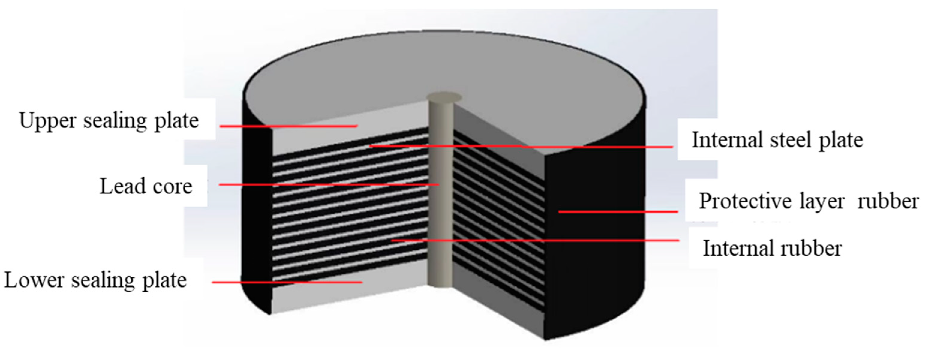
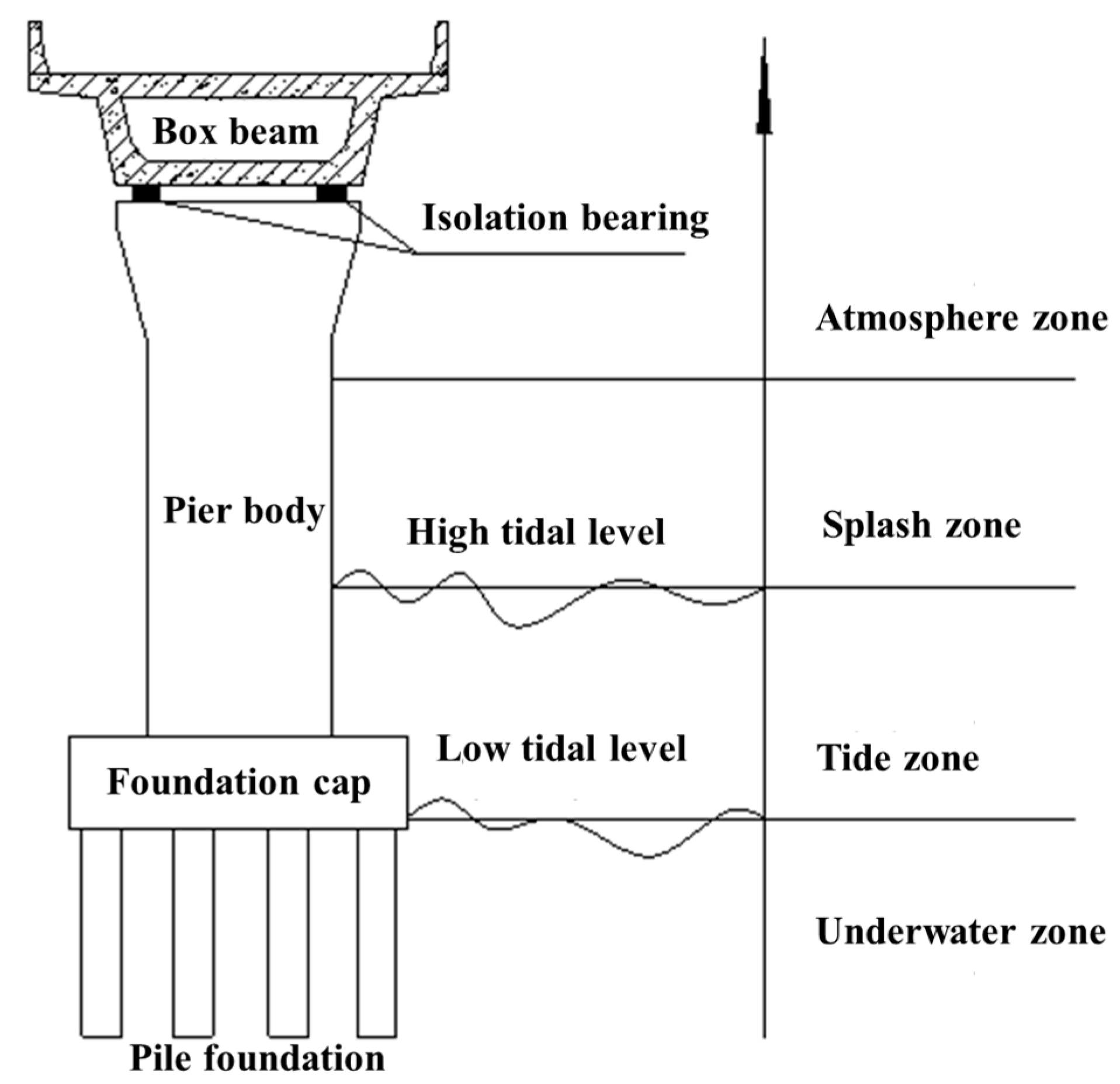
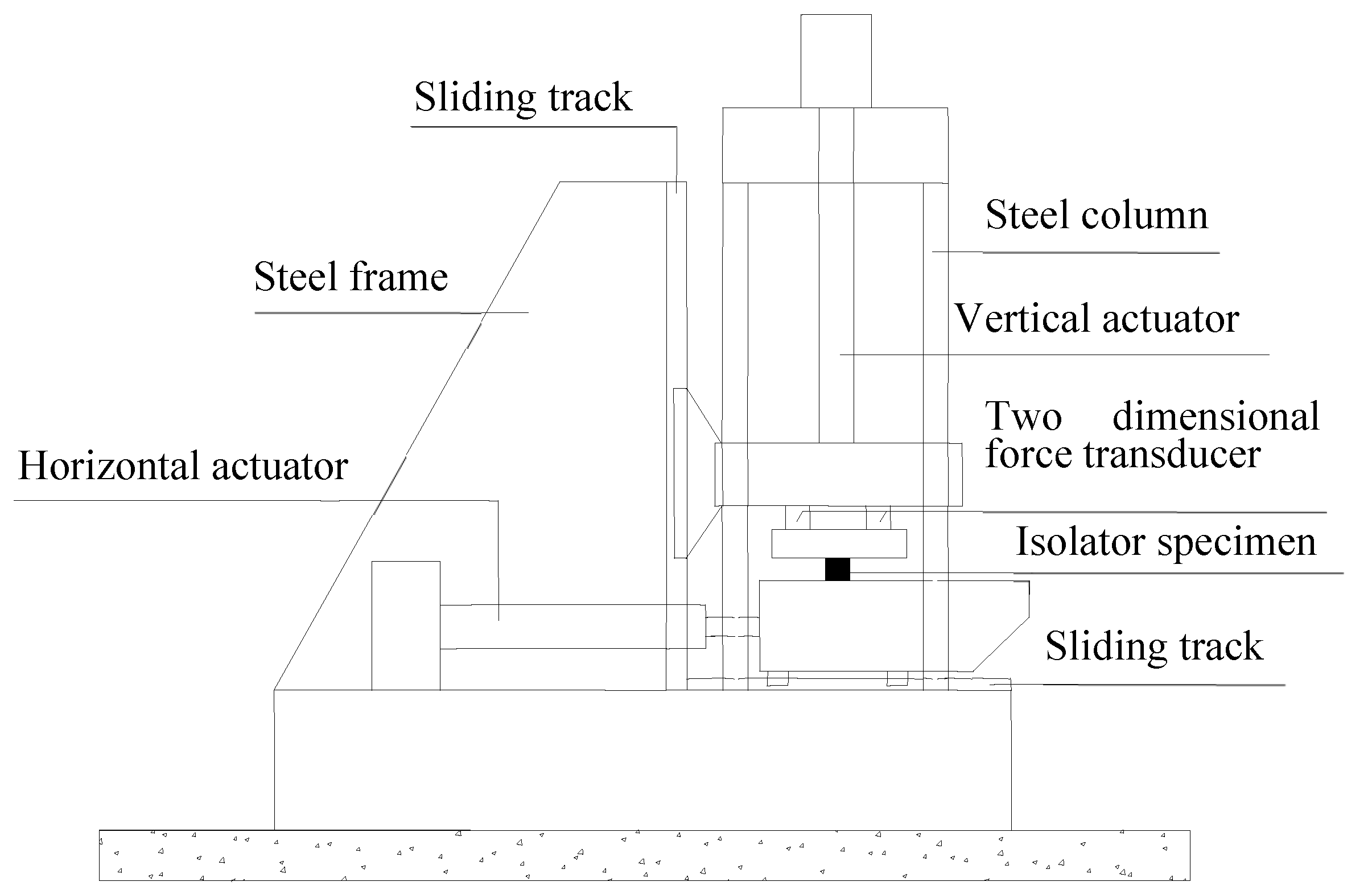
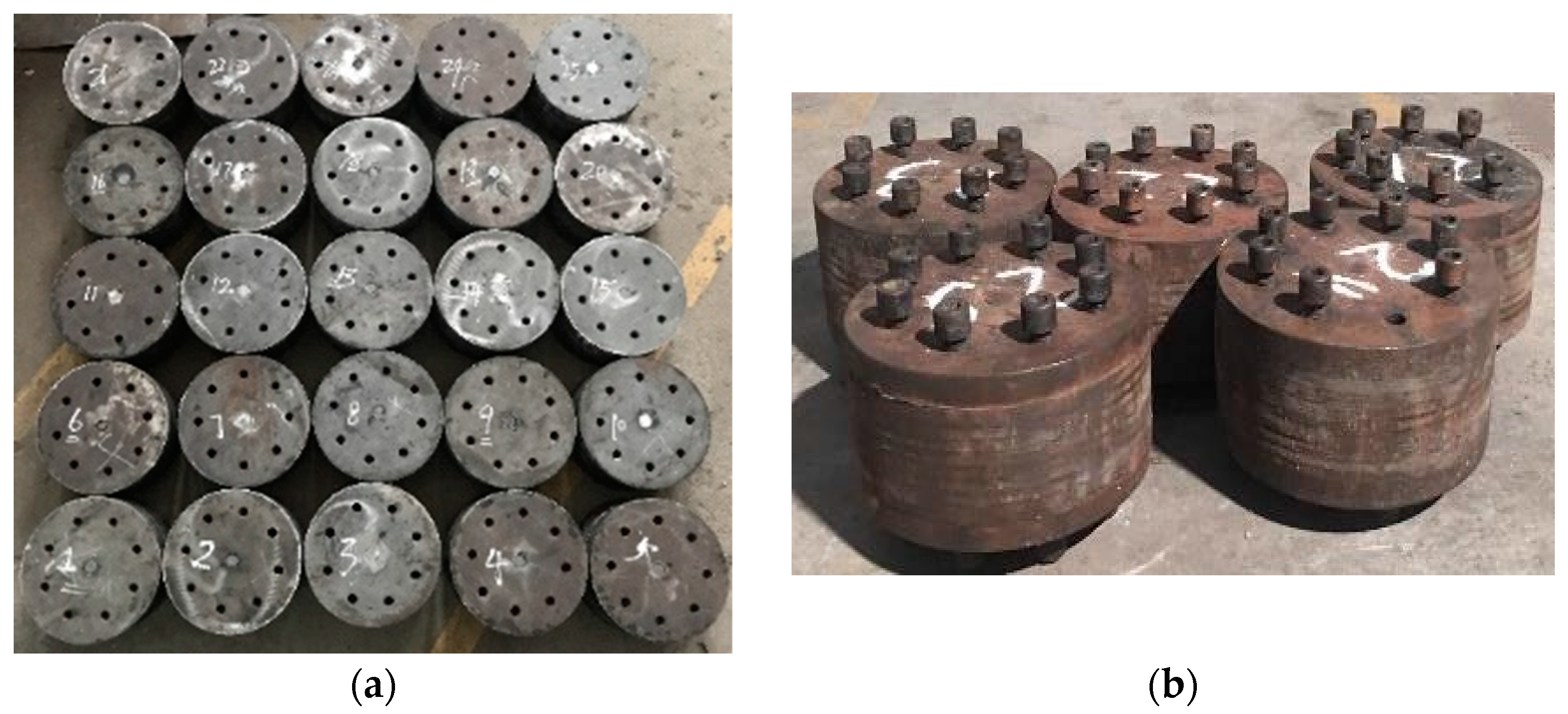
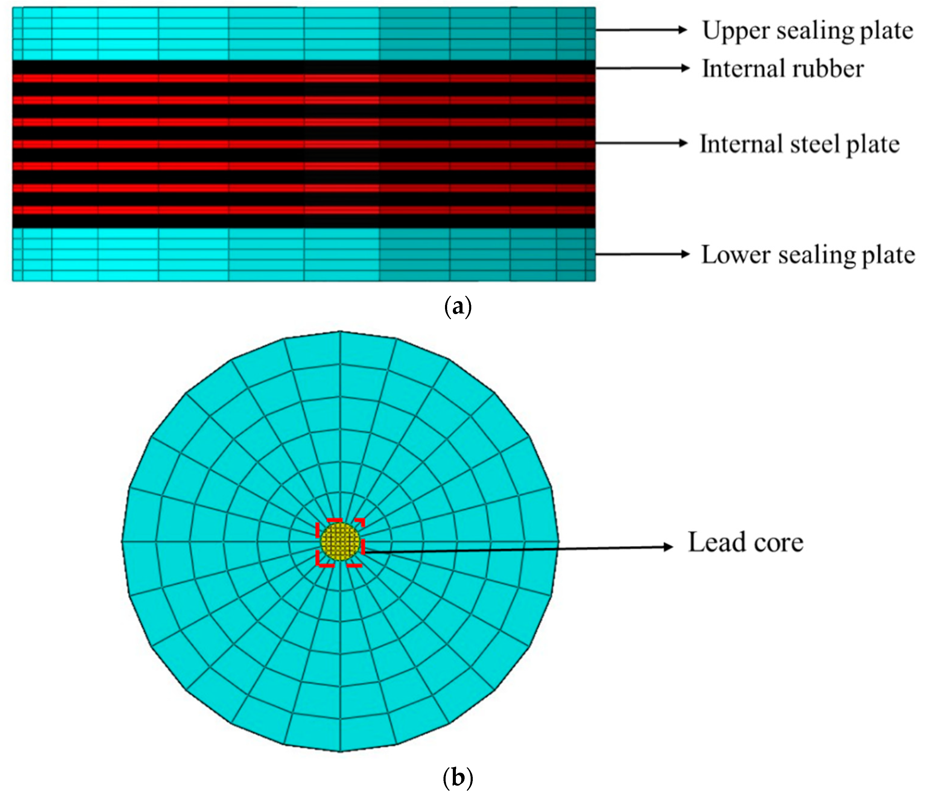
2. Overview of the Age and Seawater Alternating Corrosion Test on Lead Rubber Bearings
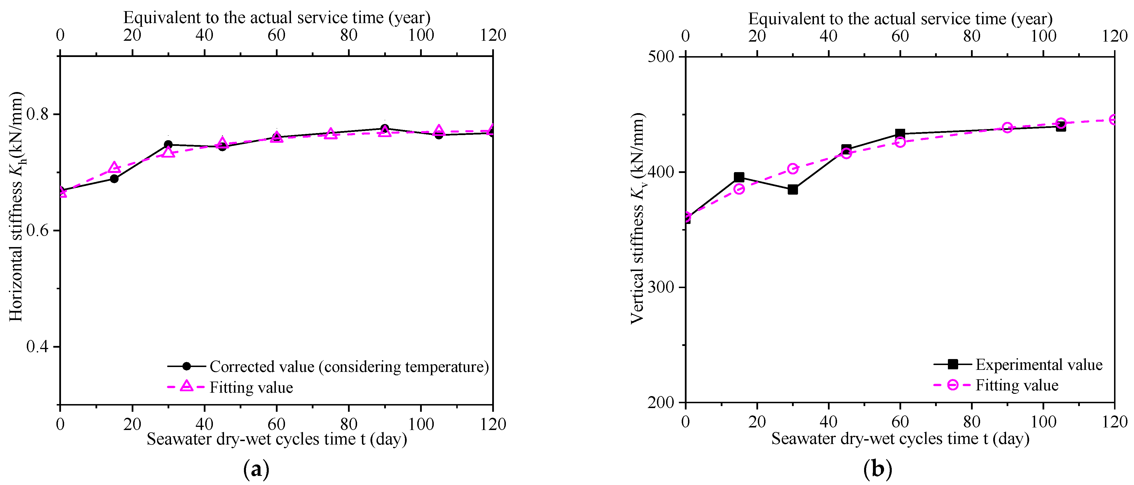
3. Basic Performance Test Results of Lead Rubber Bearings under the Alternation of Aging and Seawater Corrosion

| Bearing Type | Horizontal Equivalent Stiffness | Vertical Stiffness | ||||||
|---|---|---|---|---|---|---|---|---|
| Maximum Value | Average Value | Growth from 0 to 60 Years | Growth from 60 to 120 Years | Maximum Value | Average Value | Growth from 0 to 60 Years | Growth from 60 to 120 Years | |
| LRB | 2.5 | 1.1 | 14.3 | 2.0 | 4.7 | 1.8 | 18 | 6.3 |
4. Comparison Analysis of the Finite-Element Modelling and Experimental Results for LRB Basic Performance
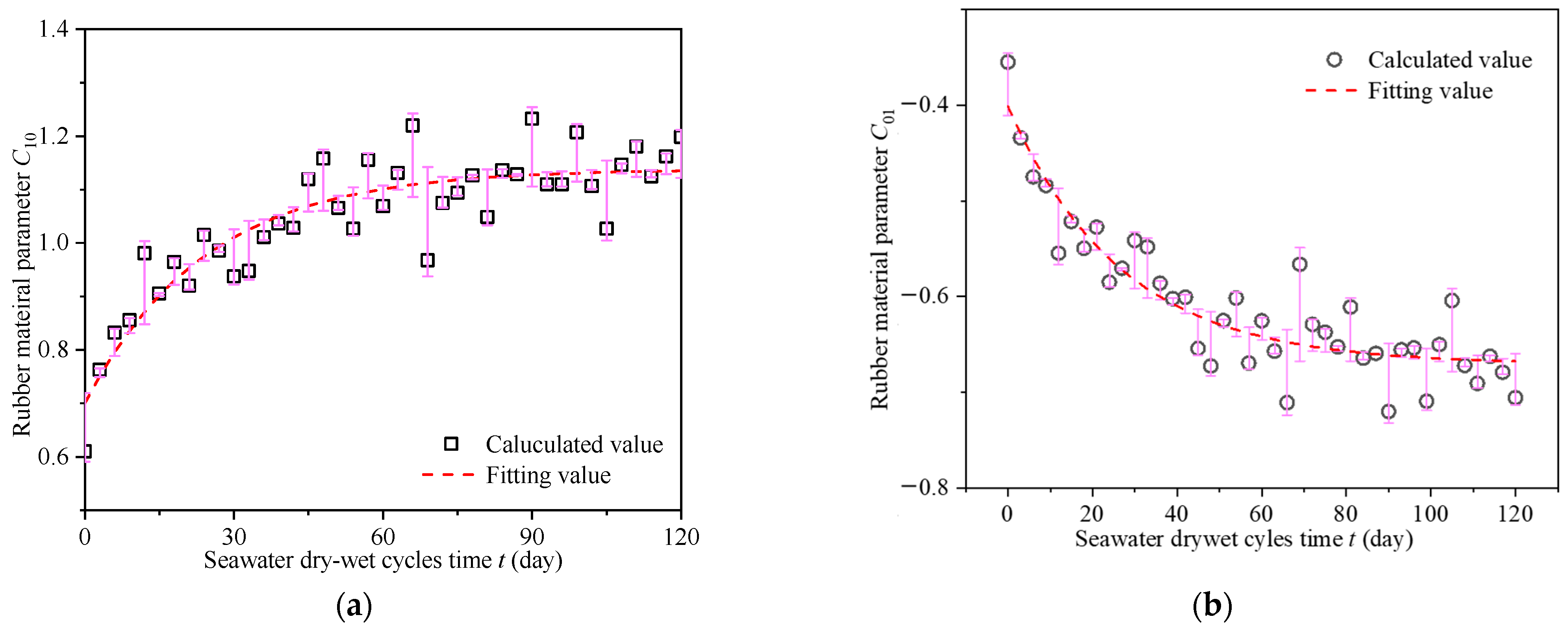
4.1. Determination of the Constitutive Parameters of the LRB Rubber Material
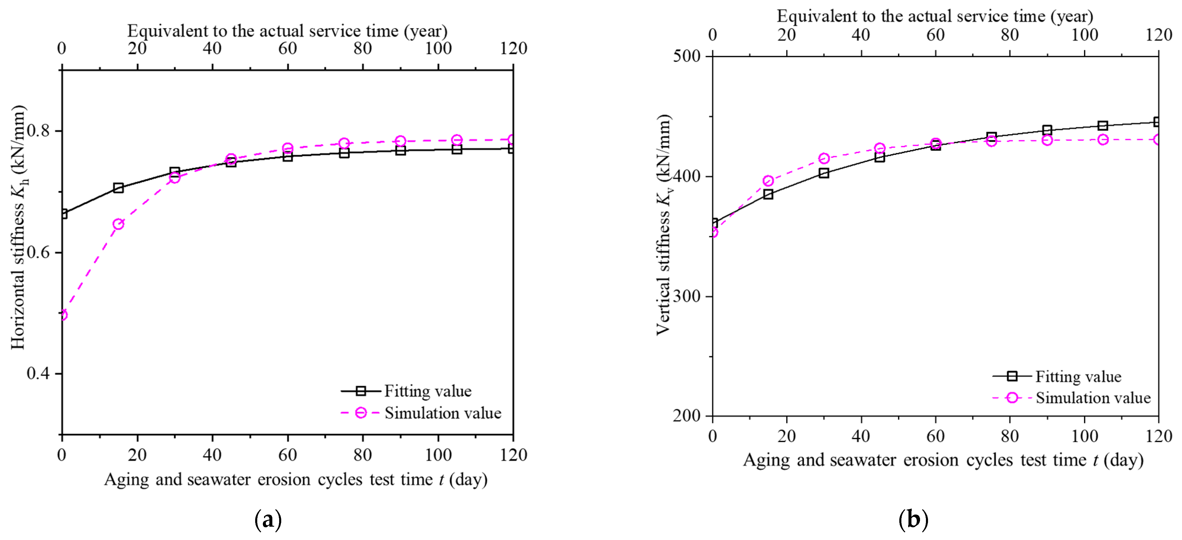
4.2. Comparative Analysis of the Simulation and Experimental Results of LRB Basic Performance
5. Time-Dependent Law of Seismic Behavior of Isolated Bridges Considering the Performance Degradation of LRBs
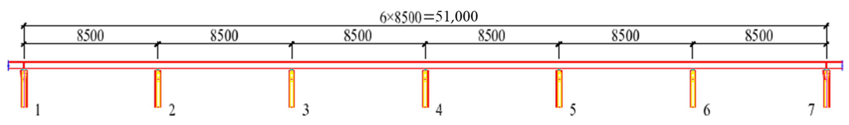
5.1. Overview of Isolated Bridges
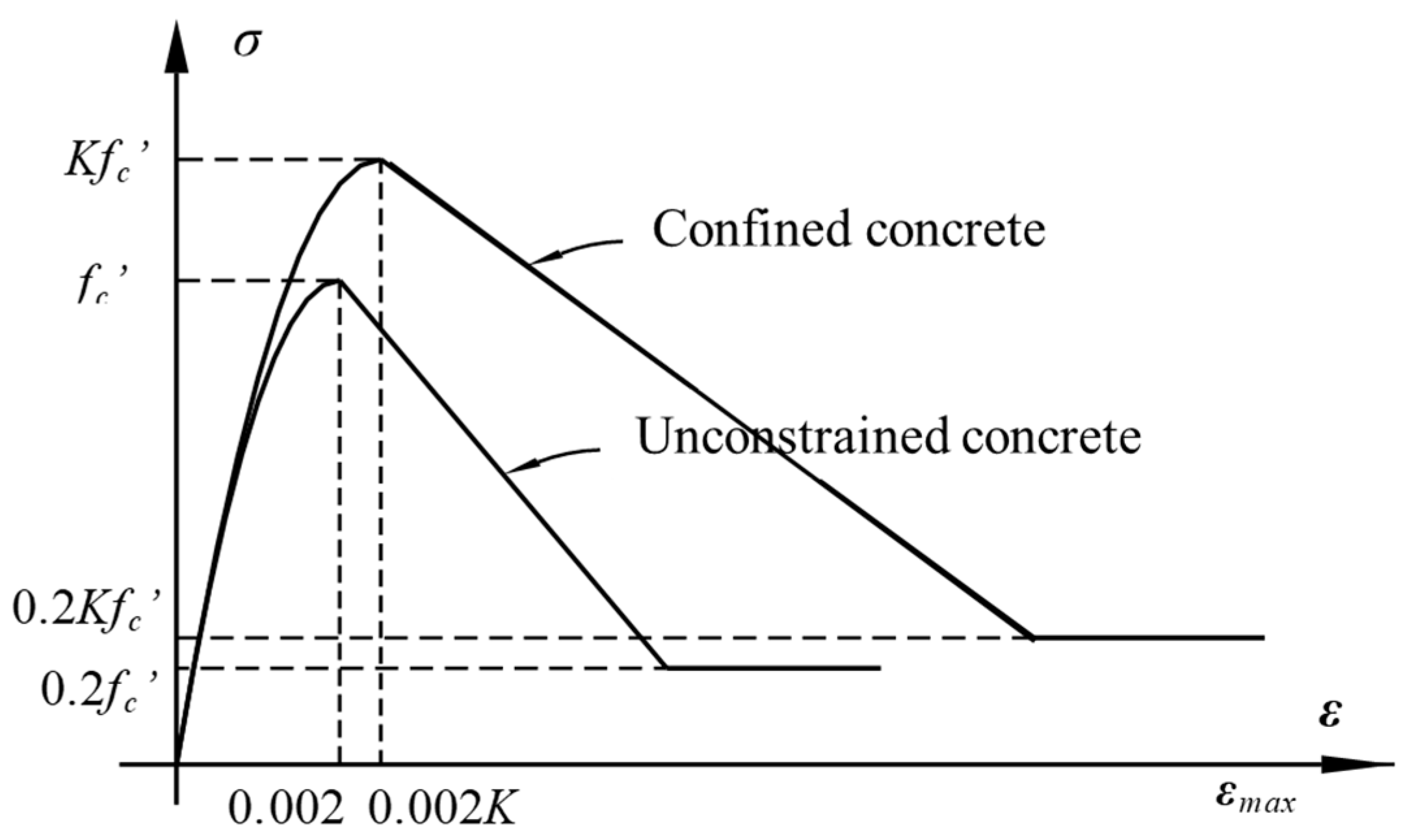
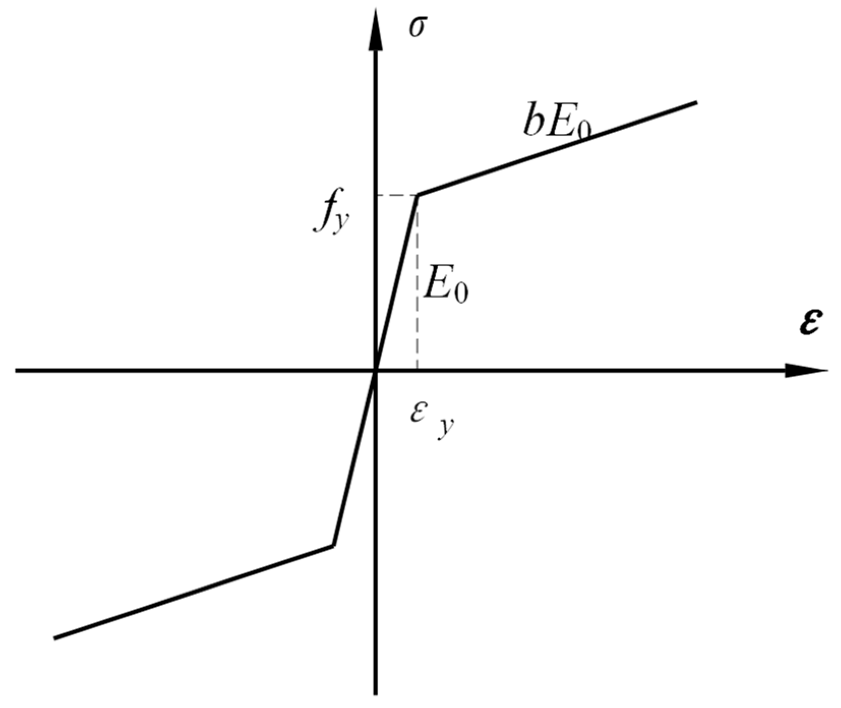
5.2. Material Constitutive Model
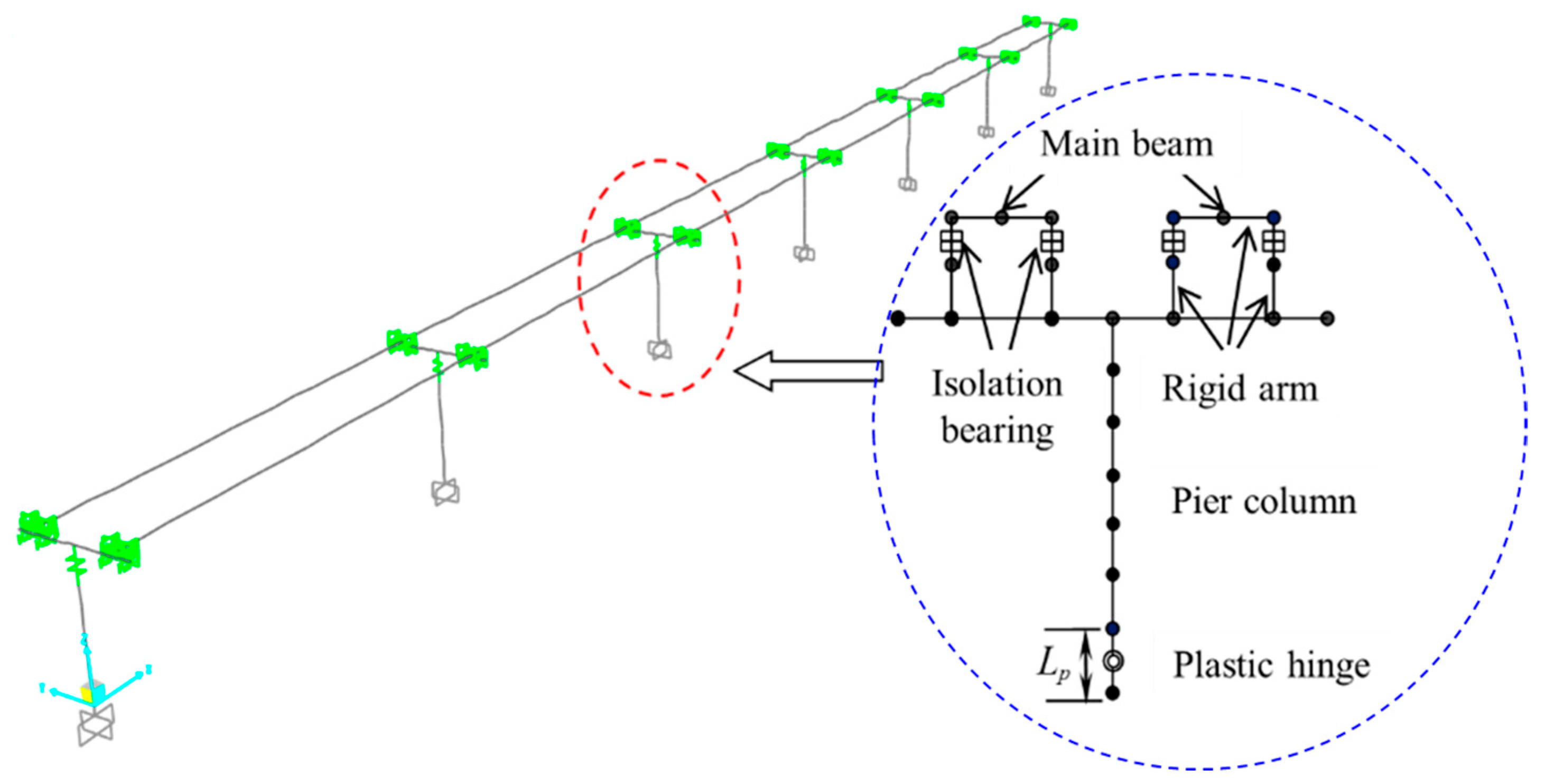
5.3. Establishment of a Bridge Finite Model and the Selection of Ground Motion
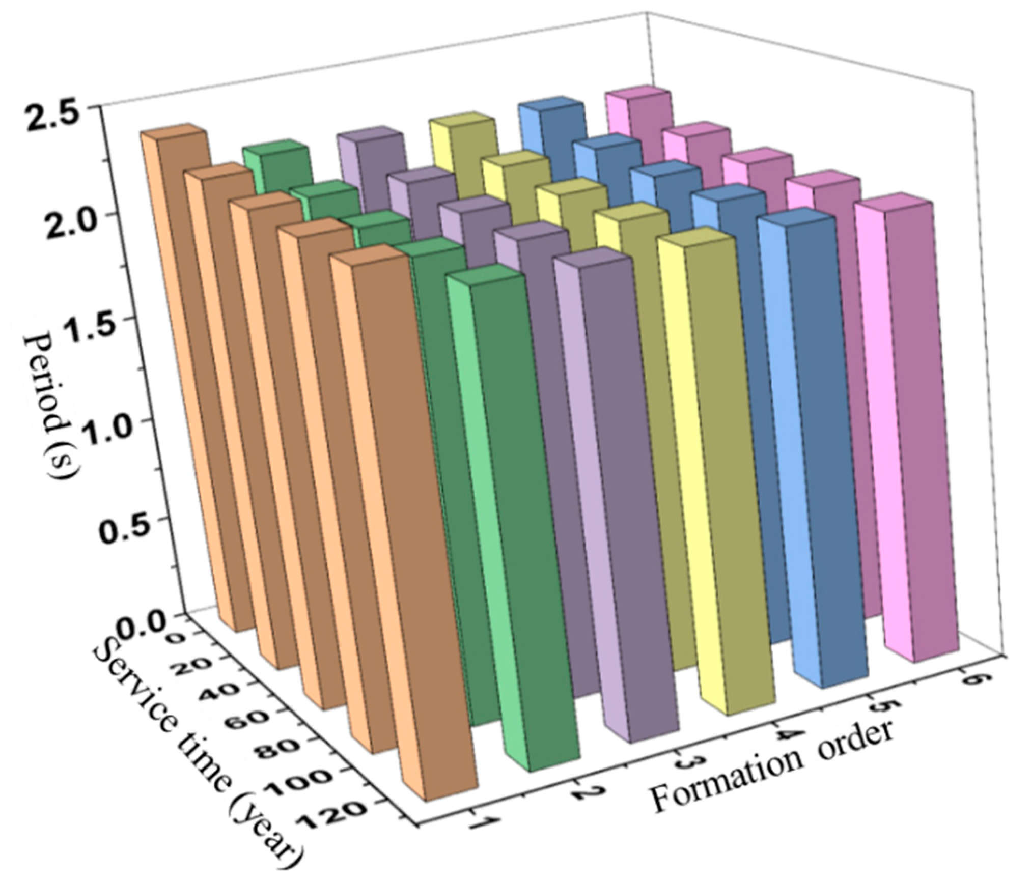
5.4. Determination of LRB Time-Varying Parameters
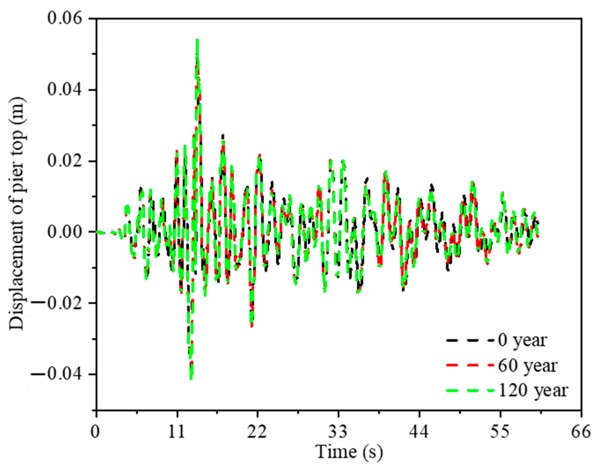
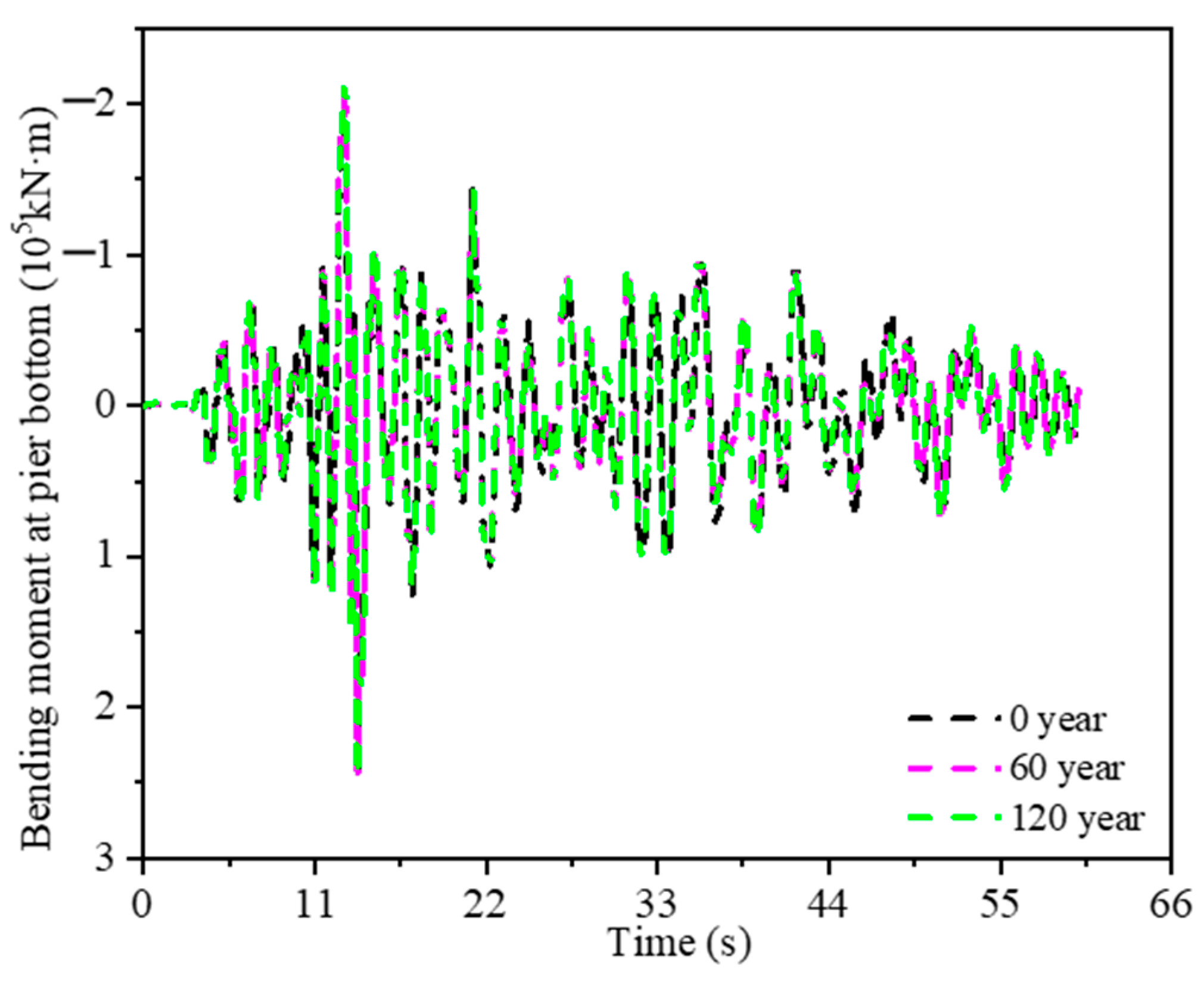
5.5. Time-Varying Law of Earthquake Resistance Performance of an Offshore Isolated Bridge Considering the Performance Degradation of Isolation Bearings
6. Summary and Conclusions
Author Contributions
Funding
Data Availability Statement
Acknowledgments
Conflicts of Interest
References
- Shen, C.; Zhou, F.; Wen, H.; Ma, Y.; Chen, Y. Test study on mechanical property of different type of isolators for bridge. China Civ. Eng. J. 2012, 45, 233–237. [Google Scholar]
- Zhuang, X.; Shen, C.; Jin, J. Experimental study on mechanical property of high damping rubber bearing for bridge. Earthq. Eng. Eng. Vib. 2006, 26, 208–212. [Google Scholar]
- Akihiro, M. Evaluation for Mechanical Properties of Laminated Rubber Bearings Using Finite Element Analysis. J. Press. Vessel. Technol. 2004, 126, 134–140. [Google Scholar]
- Xu, B.; Tang, J.-X. Experimental Studies on Durability of base isolation of using Laminated Rubber Bearings. Eathq. Resist. Eng. 1995, 4, 41–44. [Google Scholar]
- Itoh, Y.; Gu, H.S. Prediction of aging characteristics in natural rubber bearings Used in Bridges. J. Bridge Eng. 2009, 14, 122–128. [Google Scholar] [CrossRef]
- Itoh, Y.; Gu, H.; Satoh, K.; Kutsuna, Y. Experimental investigation on ageing behaviors of rubbers used for bridge bearings. Doboku Gakkai Ronbunsyuu A 2006, 62, 176–190. [Google Scholar] [CrossRef] [Green Version]
- Itoh, Y.; Yazawa, A.; Kitagawa, T. Study on environmental durability of rubber bearing for bridges. Int. Assoc. Bridge Struct. Eng. 2002, 86, 137–143. [Google Scholar]
- Itoh, Y.; Gu, H.; Satoh, K.; Yamamoto, Y. Long-term deterioration of high damping rubber bridge bearing. Doboku Gakkai Ronbunsyun A 2006, 62, 595–607. [Google Scholar] [CrossRef] [Green Version]
- Gu, H.S.; Itoh, Y. Ageing effects on high damping bridge rubber bearing. In Proceedings of the 6th Asia-Pacific Structural Engineering and Construction Conference (APSEC 2006), Kuala Lumpur, Malaysia, 5–6 September 2006. [Google Scholar]
- Wang, J.; Zhang, Z.; Li, Z. Experimental research on the vertical pressure dependence about shear properties of high damping rubber bearing. J. Railw. Eng. Soc. 2017, 34, 117. [Google Scholar]
- Wang, J.; Wei, X.; Zhuo, L.; Zheng, Z. Experimental study on vertical pressure dependency about shear properties of lead rubber bearing. Earthq. Eng. Eng. Dyn. 2016, 36, 200–206. [Google Scholar]
- Li, Y.; Zong, Z.; Huang, X.; Xia, J.; Liu, L. Experimental study on mechanical properties of high damping rubber bearing model. IOP Conf. Ser. Earth Environ. Sci. 2017, 61, 1–6. [Google Scholar] [CrossRef]
- Park, J.; Choun, Y.; Kim, M.K.; Hahm, D. Revaluation of the aging property modification factor of lead rubber bearings based on accelerated aging tests and finite element analysis. Nucl. Eng. Des. 2019, 347, 59–66. [Google Scholar] [CrossRef]
- Kalpakidis, V.I.; Constantinou, M.C. Effects of heating on the behavior of lead-rubber bearings, II: Verification of Theory. J. Struct. Eng. 2009, 135, 1450–1461. [Google Scholar] [CrossRef]
- Kalpakidis, V.I.; Constantinou, M.C. Effects of heating on the behavior of lead-rubber bearings. I: Theory. J. Struct. Eng. 2009, 135, 1440–1449. [Google Scholar] [CrossRef]
- Takenaka, Y. Experimental study on heat-mechanics interaction behavior of laminated rubber bearings. J. Struct. Constr. Eng. 2009, 74, 2245–2253. [Google Scholar] [CrossRef] [Green Version]
- Biondini, F.; Camnasio, E.; Palermo, A. Lifetime seismic performance of concrete bridges exposed to corrosion. Struct. Infrastruct. Eng. 2014, 10, 880–900. [Google Scholar] [CrossRef]
- Alipou, A.; Shafei, B.; Shinozuka, M. Performance Evaluation of Deteriorating Highway Bridges Located in High Seismic Areas. J. Bridge Eng. 2011, 16, 597–611. [Google Scholar] [CrossRef]
- Kobayashi, K. The seismic behavior of RC member suffering from chloride induced corrosion. In Proceedings of the 2nd Fib International Congress, Naples, Italy, 5–8 June 2006. [Google Scholar]
- Choe, D.E.; Gardoni, P.; Rosowsky, D.; Haukaas, T. Probabilistic capacity models and seismic fragility estimates for RC columns subject to corrosion. Reliab. Eng. Syst. Saf. 2008, 93, 383–393. [Google Scholar] [CrossRef]
- Ghosh, J.; Padgett, J.E. Aging Considerations in the Development of Time-Dependent Seismic Fragility Curves. J. Struct. Eng. 2010, 136, 1497–1511. [Google Scholar] [CrossRef]
- Zhao, G.; Ma, Y.; Jian, T.; Su, L.; Zhou, F. Effects of performance deterioration of friction pendulum bearings on seismic behavior of Hong Kong-Zhuhai-Macao isolated bridges in life-cycle period. China J. Highw. Transp. 2016, 29, 10–16. (In Chinese) [Google Scholar]
- Chen, J.-J.; Ma, Y.; Jin, H.; Guifeng, Z. Time-dependent Seismic Fragility Analysis of Offshore Bridges Based on Aging Time-dependent Law of Rubber Bearings. Sci. Technol. Eng. 2020, 20, 3699–3706. [Google Scholar]
- Farhangi, V.; Karakouzian, M. Effect of Fiber Reinforced Polymer Tubes Filled with Recycled Materials and Concrete on Structural Capacity of Pile Foundations. Appl. Sci. 2020, 10, 1554. [Google Scholar] [CrossRef] [Green Version]
- Mitoulis, S.; Titirla, M.; Tegos, I. Design of bridges utilizing a novel earthquake resistant abutment with high capacity wing walls. Eng. Struct. 2014, 66, 35–44. [Google Scholar] [CrossRef]
- Nutt, R.V.; Mayes, R.L. Comparison of typical bridge columns seismically designed with and without abutment participation using AASHTO division I-A and proposed AASHTO LRFD provisions. Task F3-1(a). In AASHTO LRFD Bridge Design Specifications; AASHTO: New York, NY, USA, 2000. [Google Scholar]
- Ma, Y.; Li, Y.; Zhao, G.; Khaloo, A. Experimental research on the time-varying law of performance for natural rubber laminated subjected to alternating of aging and seawater erosions. Eng. Struct. 2019, 17, 159–171. [Google Scholar] [CrossRef]
- Li, Y.; Ma, Y.; Zhao, G.; Zhou, F. Experimental study on the property deterioration of rubber material used as natural rubber bearing under seawater wet-dry cycles. J. Vib. Shock 2019, 38, 146–152. [Google Scholar]
- Li, Y.; Ma, Y.; Zhao, G.; Zhou, F. Experimental study on the effect of alternating ageing and sea corrosion on laminated natural rubber bearing’s tension-shear property. J. Rubber Res. 2020, 23, 151–161. [Google Scholar] [CrossRef]
- Zhao, G.; Ma, Y.; Li, Y.; Luo, J.; Du, C. Development of a modified mooney-rivlin constitutive model for rubber to investigate the effects of aging and marine corrosion on seismic isolated bearings. Earthq. Eng. Eng. Vib. 2017, 16, 815–826. [Google Scholar] [CrossRef]
- ISO 22762-1:2005; Elastomeric SeismicProtection Isolators—Part 1: Test Methods, MOD. ISO: Geneva, Switzerland, 2005.
- ISO 22762-2:2005; Elastomeric SeismicProtection Isolators—Part 2: Applications for Bridges—Specifications, MOD. ISO: Geneva, Switzerland, 2005.
- Li, Y.; Ma, Y.; Luo, J.; Zhao, G. The effect of aging on the material constant of the rubber isolator’s constitutive model Mooney-Rivlin. J. Vib. Shock. 2016, 35, 164–169. (In Chinese) [Google Scholar]
- Li, Y.; Zhao, G.; Ma, Y.; Liu, R. Effect of alternation of aging and seawater erosion on properties of rubber material used in lead rubber bearing. J. Renew. 2022, 10, 1641–1658. [Google Scholar] [CrossRef]
- Liu, R.; Ma, Y.; Zhao, G.; Li, Y.; Zheng, N. Influence of freeze–thaw cycles and aging on the horizontal mechanical properties of high damping rubber bearings. J. Rubber Res. 2022, 25, 69–77. [Google Scholar] [CrossRef]
- Huang, J.; Xie, G.; Liu, Z. Finite element analysis of hyperelastic rubber material based on Mooney-Rivlin model and Yeoh model. China Rubber Ind. 2008, 8, 467–471. (In Chinese) [Google Scholar]
- Ye, A.; Guan, Z. Seismic Design of Bridges, 2nd ed.; China Communications Press: Beijing, China, 2011. [Google Scholar]
- Liu, C. Seismic Response and Seismic Performance Analysis of Bridge Structures, 1st ed.; China Construction Industry Press: Beijing, China, 2009. [Google Scholar]
- CJJ 166-2011; Code for Seismic Design of Urban Bridges. Tongji University: Shanghai, China, 2011.
- Li, Y. Study on Bidge Isolation Bearings Performance Deterioration Law under Aging-Seawater Erosion Alternation. Ph.D. Thesis, Guangzhou University, Guangzhou, China, 2021. [Google Scholar]


| Test Specimen | Shear Modulus (MPa) | Diameter of Rubber Bearings (mm) | Thickness of Cover Steel Plate (mm) | Thickness of Single Inner Rubber (mm) | Number of Layers of Inner Rubber | Thickness of Inner Steel Plate (mm) | Number of Inner Steel Plates | Total Thickness of Rubber Layers (mm) | Bearing Height (mm) | First Shape Factor S1 | Second Shape Factor S2 |
|---|---|---|---|---|---|---|---|---|---|---|---|
| LRB | 0.8 | 220 | 20 | 5.3 | 8 | 3 | 7 | 42.4 | 103.4 | 8.96 | 5.2 |
| Test Body and Its Number | Total Test Time (days) | Speedup Ratio of Test | Equivalent to the Actual Service Time (years) | Test Temperature (°C) | Equivalent to the Actual Service Environment Temperature (°C) | Time Ratio of Drying and Soaking | Test Method | Sampling Method | Test Content |
|---|---|---|---|---|---|---|---|---|---|
| LRB21#–LRB25# | 120 | 376 | 120 | 80 | 20 | 2:1 | (a) Specimens were first soaked for one day in artificial seawater in the aging box at 80 °C. (b) Then, the specimens were dried for two days in aging box at 80 °C without artificial seawater. (c) Above cycle test was carried out until the end of the 120-day test. | Specimens LRB21#–LRB25# were sampled at 0, 15, 30, 45, 60, 90, 105, and 120 days, respectively. | (1) Horizontal stiffness; (2) Vertical stiffness. |
| Parameter | Deviation (%) | ||
|---|---|---|---|
| Maximum Value | Minimum Value | Average Value | |
| C10 | 15.2 | 0.1 | 4.7 |
| C01 | 14.7 | 0 | 4.2 |
| Deviation of Horizontal Equivalent Stiffness (%) | Deviation of Vertical Stiffness (%) | ||||
|---|---|---|---|---|---|
| Maximum | Minimum | Mean | Maximum | Minimum | Mean |
| 25.1 | 0.7 | 5 | 3.2 | 0.4 | 2.1 |
| Bearing Locations | Bearing Type | Vertical Bearing Capacity (kN) | Yield Force (kN) | Initial Shear Stiffness (kN/mm) | Post-Yielding Stiffness (kn/mm) | Equivalent Horizontal Stiffness (kn/mm) | Vertical Stiffness (kN/mm) |
|---|---|---|---|---|---|---|---|
| Side pier | LRB800 | 8000 | 442 | 17.2 | 2.7 | 3.9 | 1667 |
| Middle pier | LRB1600 | 16,000 | 802 | 47.9 | 7.4 | 10.5 | 4724 |
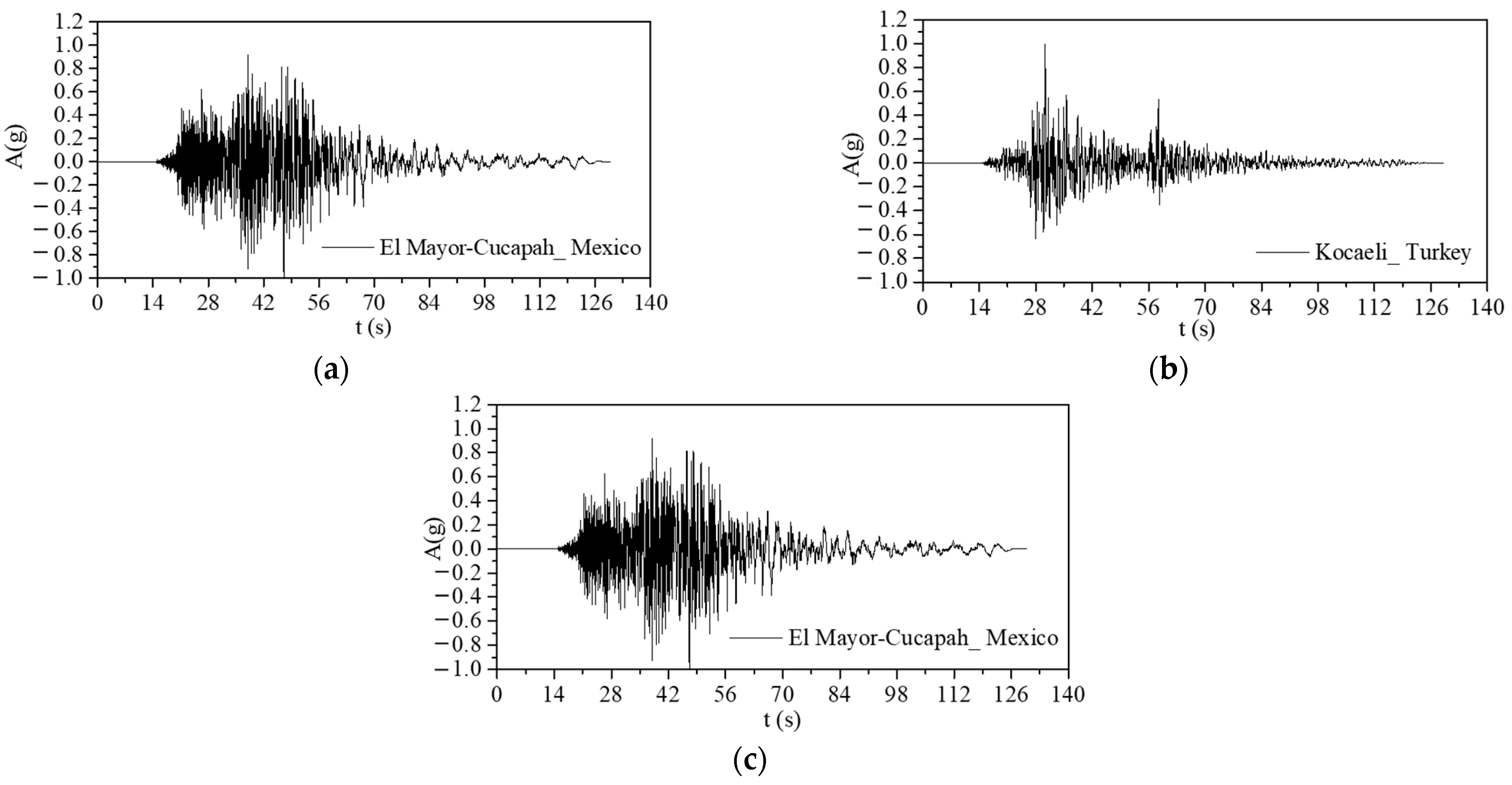
| Number | RSN | Earthquake Name | Year | Station Name | Magnitude | Rjb (km) | Vs30 (m·s−1) |
|---|---|---|---|---|---|---|---|
| 1 | 721 | Superstition Hills-02 | 1987 | “El Centro Imp. Co. Cent” | 6.54 | 18.2 | 192.05 |
| 2 | 1177 | Kocaeli_ Turkey | 1999 | “Zeytinburnu” | 7.51 | 51.98 | 341.56 |
| 3 | 5832 | El Mayor-Cucapah_ Mexico | 2010 | “TAMAULIPAS” | 7.2 | 25.32 | 242.05 |
| Service Time (Years) | 0 | 30 | 60 | 90 | 120 | |
|---|---|---|---|---|---|---|
| Side pier LRB800 | Keq (kN/mm) | 3.9 | 4.2707 | 4.4201 | 4.4756 | 4.4962 |
| K1 (kN/mm) | 17.2 | 19.2014 | 19.9007 | 20.1311 | 20.2071 | |
| K2 (kN/mm) | 2.7 | 3.0142 | 3.1239 | 3.1601 | 3.172 | |
| Qy (kN) | 442 | 431.8015 | 433.0988 | 434.4001 | 435.7052 | |
| Middle pier LRB1600 | Keq (kN/mm) | 10.5 | 11.4981 | 11.9002 | 12.0497 | 12.1052 |
| K1 (kN/mm) | 47.9 | 53.4737 | 55.4211 | 56.0628 | 56.2743 | |
| K2 (kN/mm) | 7.4 | 8.2611 | 8.5619 | 8.6611 | 8.6937 | |
| Qy (kN) | 802 | 783.495 | 785.849 | 788.2101 | 790.5782 | |
Disclaimer/Publisher’s Note: The statements, opinions and data contained in all publications are solely those of the individual author(s) and contributor(s) and not of MDPI and/or the editor(s). MDPI and/or the editor(s) disclaim responsibility for any injury to people or property resulting from any ideas, methods, instructions or products referred to in the content. |
© 2023 by the authors. Licensee MDPI, Basel, Switzerland. This article is an open access article distributed under the terms and conditions of the Creative Commons Attribution (CC BY) license (https://creativecommons.org/licenses/by/4.0/).
Share and Cite
Li, Y.; Ma, Y.; Zhao, G.; Liu, R. Study on the Basic Performance Deterioration Law and the Application of Lead Rubber Bearings under the Alternation of Aging and Seawater Erosion. Buildings 2023, 13, 360. https://doi.org/10.3390/buildings13020360
Li Y, Ma Y, Zhao G, Liu R. Study on the Basic Performance Deterioration Law and the Application of Lead Rubber Bearings under the Alternation of Aging and Seawater Erosion. Buildings. 2023; 13(2):360. https://doi.org/10.3390/buildings13020360
Chicago/Turabian StyleLi, Yanmin, Yuhong Ma, Guifeng Zhao, and Rong Liu. 2023. "Study on the Basic Performance Deterioration Law and the Application of Lead Rubber Bearings under the Alternation of Aging and Seawater Erosion" Buildings 13, no. 2: 360. https://doi.org/10.3390/buildings13020360