

Shear Strength of Concrete Beams without Stirrups Made with Recycled Coarse Aggregate


Department of Civil Engineering, College of Engineering, American University of Sharjah, Sharjah P.O. Box 26666, United Arab Emirates
*
Author to whom correspondence should be addressed.
Buildings 2023, 13(1), 75; https://doi.org/10.3390/buildings13010075
Submission received: 13 December 2022
/
Revised: 21 December 2022
/
Accepted: 26 December 2022
/
Published: 28 December 2022
(This article belongs to the Collection Green and Sustainable Building Materials)
Abstract
:Eco-friendly concrete that considers waste material and requires less energy for production is in demand because it produces less carbon dioxide, reduces the consumption of raw material, and can be a cheaper option to conventional concrete. The objectives of this study are to investigate the shear behavior of reinforced concrete beams made with locally produced recycled coarse aggregate from construction demolition waste, study the important parameters that affect the shear strength and ductility, and check the applicability of the available theoretical shear strength predictive equations to recycled concrete. An experimental program that involved the testing of fifteen half-scale beams in shear without stirrups was carried out with a theoretical component. Results of the study showed that recycled concrete beams employing 50% recycled coarse aggregate had on average 27% lower shear strength than corresponding beams made with natural aggregate when tested at a shear span-to-depth ratio equal to 1.15, and almost the same strength as the natural aggregate beams when subjected to a shear span-to-depth ratio equal to 2.5. On the other hand, the average shear strength of beams utilizing 100% recycled aggregate was lower by 5% than the strength of their natural aggregate counterparts, irrespective of the shear span-to-depth ratio. The longitudinal steel reinforcement ratio had less effect on the shear strength provided by recycled concrete beams than on those made with natural aggregate, possibly due to the reduced ability of such concrete to develop strong dowel action. Although the use of higher strength concrete improved the shear strength of recycled aggregate beams, there was no clear correlation between the square-root of the concrete compressive strength and the shear strength provided by the concrete. The theoretical part of the study showed that the ACI 318 code and the strut-and-tie method can be reliably used to predict the shear strength of concrete made with recycled coarse aggregate employed in shallow and deep beams, respectively.
1. Introduction and Background
The rapid increase in the global population over the years has led to an increase in demand for buildings and infrastructure. Moreover, the immigration of people from rural areas to cities for work opportunities has forced engineers to look for construction materials that can satisfy the increased demand for housing. Reinforced concrete (RC) was and still is considered to be the most suitable and economical material for structural applications. This is exactly why concrete is the most produced unnatural material on the planet [1]. In recent years, sustainability has become a requirement for the choice of construction materials due to worries emerging from the extensive demand for buildings and infrastructure.
Coarse aggregate consists of around 50–75% of typical concrete mixes by volume and is one the main contributor to the strength and performance of the concrete. The main source for aggregate production is mining, which is done by blasting blocks of rocks from mountains and then crushing them to the required size. This process endangers the environment in various ways, such as destroying natural topography, disturbing habitats of wild animals, eroding soils, and producing huge quantities of carbon dioxide [2]. Moreover, concrete waste from construction demolition and precast concrete plants rejects, which are then dumped in landfills, place further burdens on the environment. To alleviate the negative impacts of the production of concrete, many countries have started to use construction and demolition waste (CDW) through recycling. Special facilities nowadays routinely crush the CDW into fine and coarse aggregate for use in new roads, pavements, and walkways, or for landscaping purposes. Utilization of CDW can abate environmental concerns related to natural aggregate depletion and waste concrete disposition.
There have been many published studies in the literature on the mix design, mechanical properties, and durability of concrete made with recycled aggregates [3,4,5,6,7,8,9]. In general, work on structural behavior, structural member strength characteristics, and structural design recommendations is far behind research work at the material level. The flexural strength of under-reinforced concrete beams does not depend much on the mechanical properties of the concrete. Additionally, the axial capacity of tied or spiral reinforced concrete columns can be somewhat predicted straight from the steel and concrete material strengths. However, shear strength of concrete inside structural elements is a very complex phenomenon that often cannot be extrapolated directly from the properties of the involved materials with ease. Several studies have been conducted on replacing the natural aggregates in concrete with alternative materials, such as coal bottom ash [10], waste glass [11,12], waste marble powder [13], and other materials [14,15]. However, this study focuses on replacing the natural aggregates with recycled aggregates from demolition waste. In particular to examine the shear strength of reinforced concrete members made with recycled coarse aggregate (RA) derived from demolition waste and subjected to loads resulting in different shear span to depth ratios. Given the complexity of shear strength in concrete and the limited research on using recycled aggregates, it is necessary to further investigate the use of RA in concrete structures.
While almost all previous research agrees that the shear failure pattern of recycled aggregate (RA) concrete beams is similar to natural aggregate (NA) concrete beams, there is no consensus on the effect of using RA on the shear strength. Gonzalez and Fernando [16] considered beams made with 50% RA and different amounts of shear reinforcement in their study. The beams were tested with a span-to-depth ratio () of 3.3. The test results were compared to the predictions of the Modified Compression Field Theory and the outcomes of shear strength provisions in different building codes. All the predictions were found conservative for up to a 50% RA replacement ratio. Similar conclusions were obtained by Choi and Yun [17] who considered two variables in their study: (1) replacement ratio (R = 0%, 30%, 60%, and 100%), and (2) span-to-depth ratio (2.0, 2.5, 3.0, 4.0, and 5.0). They concluded that the ACI 318 code can be adequately used to predict the shear strength of beams containing RA. To further investigate the effect of different replacement ratios on the shear strength of beams, Rahal and Alrefaei [18] experimentally tested RA beams with 0%, 10%, 20%, 35%, and 100% replacement ratios. They concluded that both the shear strength and deflection of the RA concrete beams were higher than those of the control NA beams. In a study published later [19], Rahal and Alrefaei found that the shear strength of beams made with RA was not strongly influenced by the factor . Contrary to their earlier study on the subject, they reported that a coarse aggregate replacement ratio over 15% reduced the shear strength by up to 21%. Nevertheless, in order to use the code equations of the ACI and the CSA when utilizing RA, they proposed a reduction factor of 20% on the shear strength provided by concrete equations. Similarly, Ajdukiewicz and Kliszczewicz [20] considered the source of the RA, the combination and type of fine and coarse aggregate (% natural or recycled), and the concrete compressive strength. They concluded that the difference in behavior of beams made with RA and beams made with NA was insignificant, regardless of the recycled aggregate replacement ratio. Knaack and Kurama studied the flexural and shear behavior of 12 twin pairs of normal strength concrete beams with either 50% or 0% RA ratios [21]. The authors concluded that the use of recycled aggregate has much more influence on the stiffness of beams than on the shear resistance.
Fathifazl et al. [22] argued that the reduction in the shear strength and properties of RC beams made with RA is not inherited but rather is due to the conventional concrete mix design procedure. They tested twenty beams made using two methods: the first was a mix made with NA and proportioned as per the ACI, and the second was a mix made with RA, but the proportions were calculated using their proposed Equivalent Mortar Volume (EMV) method. The use of the EMV method increased the aggregate interlock mechanism and consequently the shear resistance. They also found that the ACI, CSA, and Eurocode could be used to predict the shear strength of RA beams having different shear span-to-depth ratios. This conclusion was also found by Lian et al. [23], who considered R = 25% and different ratios. Test results by Snag-Woo et al. [24] showed that the response of RC beams with 50% and 100% recycled aggregate and effective depth less than 600 mm were similar to that of RC beams with natural aggregates in terms of shear behavior, crack patterns, and strength characteristics, a conclusion which was also shared by Deng et al. [25]. To explore the effect of the longitudinal reinforcement on the shear strength, Arezoumandi et al. [26] tested six beams made with conventional concrete and then crushed them to produce the RA, which were later used to cast new beams for comparison purposes. The beams had different amounts of longitudinal reinforcement but no transverse reinforcement. The results showed that the propagation of cracks in both NA and RA beams was similar, and those with higher longitudinal reinforcement ratios had higher capacity. They also concluded that all the considered theoretical methods to predict shear strength of the beams in their study were feasible and could be applied to beams made with 100% RA. That study was extended by the authors later to include R = 50%, and the previous findings were confirmed regardless of the RA replacement ratio [27]. Schubert et al. found similar results using RA when studying the shear of RC slabs without shear reinforcement [28].
Deresa et al. [29] summarized the major experimental studies about the structural behavior of a large number of RA concrete beams available in the literature. The paper concluded that the analysis that was conducted on the available experimental results indicated that NA and RA beams with the same characteristics, such as compressive strength, ratio, and steel reinforcement ratio, had similar failure modes and crack propagation patterns. Additionally, the shear strength of RA beams was slightly lower compared to corresponding NA beams. Higher longitudinal steel reinforcement ratios increased the shear strength of the RA beam due to dowel action and increased depth of the compression zone. Additionally, it was found that the ratio highly affected the shear strength.
Pacheco et al. conducted uncertainty analysis on a gathered database of RA concrete beams with and without shear reinforcement [30]. Their database included slender beams and four-point testing setup and did not account for beams where the loading was close to the support. They concluded that the building codes overestimated the shear strength of beams without shear reinforcement. A similar study on the subject was carried out by Tošic’ et. al. [31], in which they used Euro Code 2 for predicting the shear strength of RC beams in a database excluding short shear span-to-depth ratios < 2.4. Pradhan et al. used a database with a wide range of parameters to investigate the effect of stirrups on the shear resistance mechanism [32]. They also conducted experimental work on seven RA beams and seven NA beams and then compared the results to various prediction codes and methods. However, all the tested beams had an and were tested under four-point loading protocol.
The current study is aimed at investigating the effects of various parameters with varying ranges on the shear strength of concrete beams made with coarse recycled aggregate from old demolition waste. It adds valuable information and data to the available literature on the subject and will help structural code developers in adopting shear strength prediction equations for recycled concrete. Furthermore, in world where big data is appreciated, more records are necessary for enhancing building codes that promote sustainable material, especially for behavior that is complicated and empirically based.
The main objective of this study is to investigate the shear strength behavior of reinforced concrete beams made with recycled coarse aggregate from construction demolition waste. This research aims to compare the performance of the recycled concrete beams to corresponding beams made with natural aggregate and to study the effect of key parameters such as the coarse aggregate replacement ratio, the concrete compressive strength, the shear span-to-depth ratio, and the longitudinal steel reinforcement ratio on the shear strength of the recycled aggregate concrete beams. Additionally, this study aims to evaluate the feasibility of using theoretical approaches to predict the shear strength of the recycled aggregate concrete beams without stirrups.
To achieve these objectives, the research herein involved both experimental and theoretical components. The experimental part consisted of laboratory tests up to failure of 1500 mm-long beams with 150 mm × 300 mm cross-sections that were properly reinforced for flexure with longitudinal steel rebars in the tension zone. The beams were tested in the structural laboratory as simple spans inside a universal testing machine (UTM) under displacement-controlled condition, in which the actuator’s load and extension were recorded periodically during the tests. Two recycled coarse aggregate replacement ratios, 50% and 100%, were considered in addition to the control specimens (0%). Two concrete compressive strengths were targeted in the study, namely, = 25 MPa and 35 MPa, and two shear span-to-depth ratios were investigated, namely, = 1.15 and 2.50. In addition, two effective flexural steel reinforcement ratios, = 0.0103 and 0.016, were considered.
Instrumentation of the tested beams consisted of strain gauges installed on the steel rebars and concrete surface in the compression zone at the location of the applied load. Additionally, linear variable differential transformers (LVDTs) were installed diagonally across the expected inclined cracks in the maximum shear region. Additionally, a vertical LVDT was fixed beneath the beam at the load location to measure the deflection. The theoretical part of this study involved the use of the ACI 318-14 [33] and ACI 318-19 [34] provisions to predict the shear strength of concrete beams loaded at = 2.5 and the pseudo strut-and-tie simplified model by Matamoros and Wong [35] to predict the shear strength of concrete beams loaded at = 1.15. The ultimate goal of the study is to make shear design recommendations with regard to the potential use of locally produced recycled coarse aggregate in concrete beams without stirrups.
2. Experimental Program
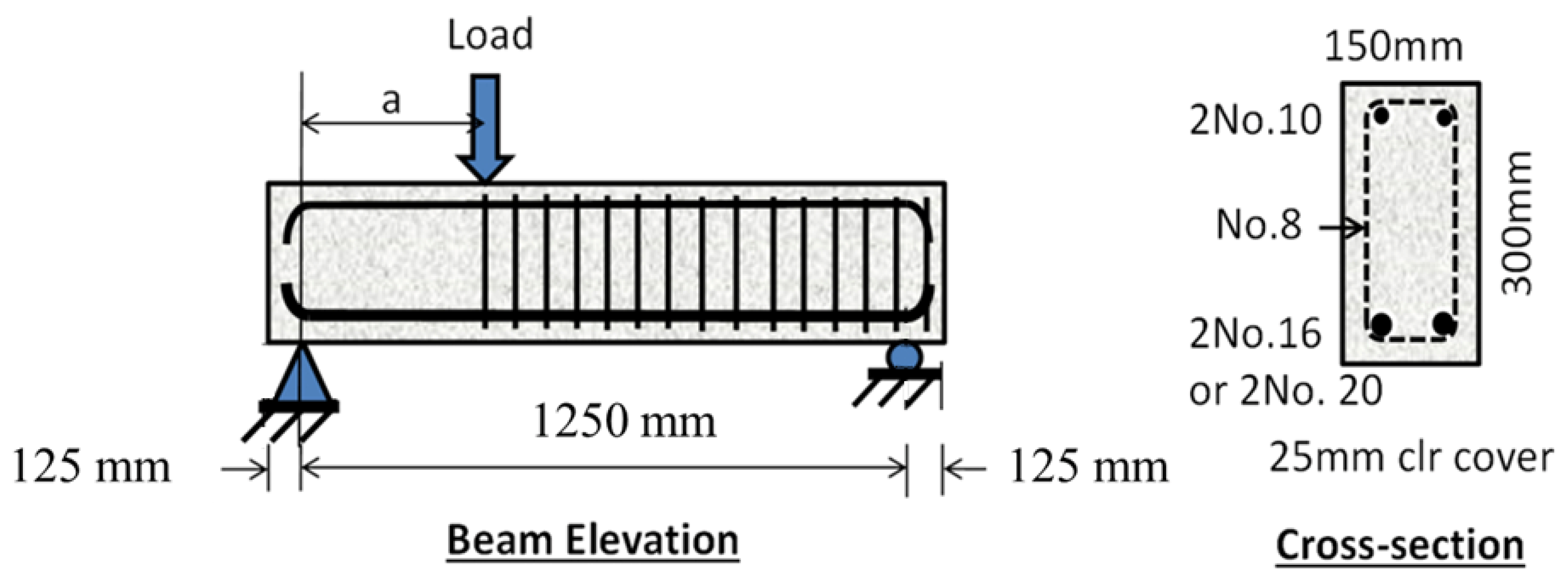
The experimental part of the study consisted of fabricating and casting fifteen half-scaled beams of length 1500 mm and rectangular cross-section of 150 mm × 300 mm. They were simply supported at a span of 1250 mm and subjected to a single concentrated load between the supports. All beams were reinforced with two No. 10 bars at the top and two No. 16 or two No. 20 bars at the bottom, as Figure 1 shows. The instrumented region of the beam that is subjected to high shear was free from stirrups, whereas the remaining region had No. 8 stirrups at 100 mm spacing in order to protect that region from possible premature failure.
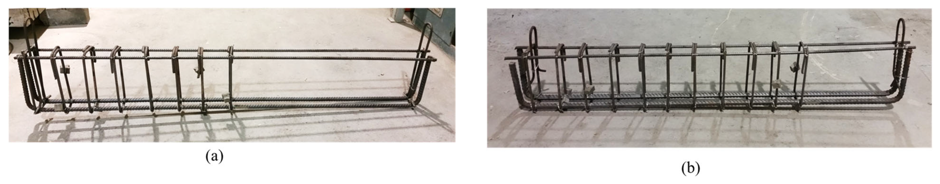
Additionally, the bottom longitudinal steel rebars were hooked at their ends to prevent slippage and bond failure during testing. Figure 2 shows samples of the steel cages for different ratios.
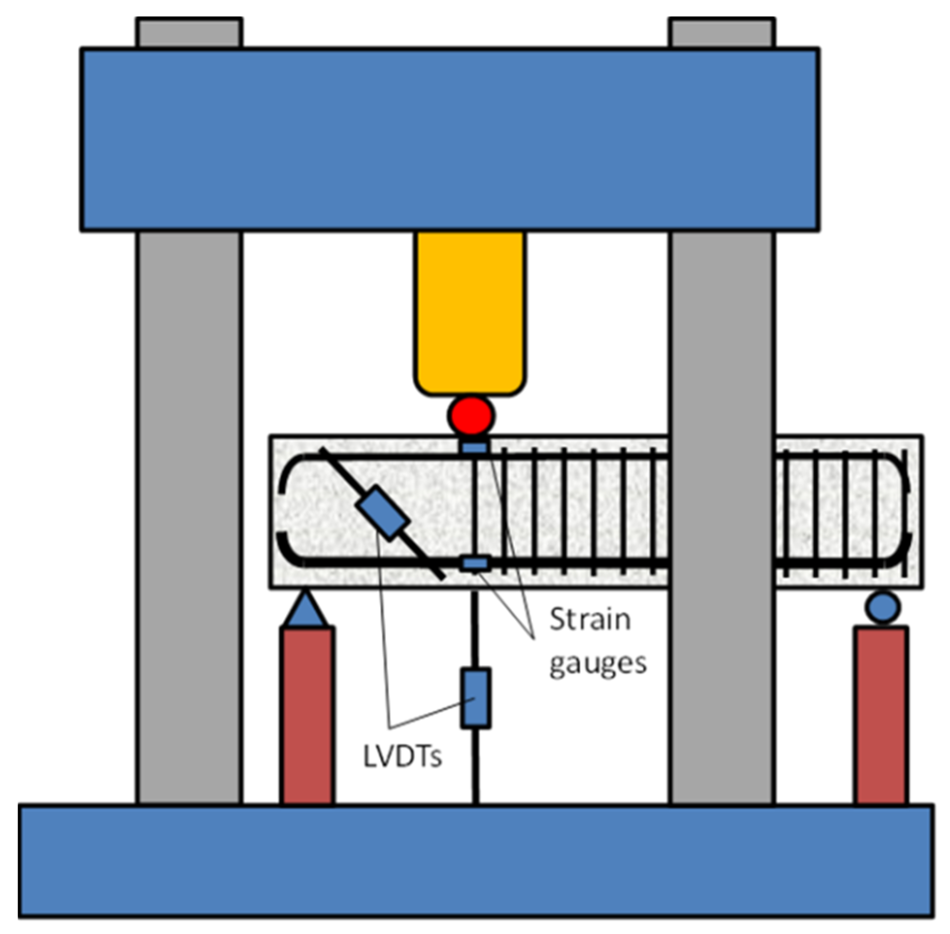
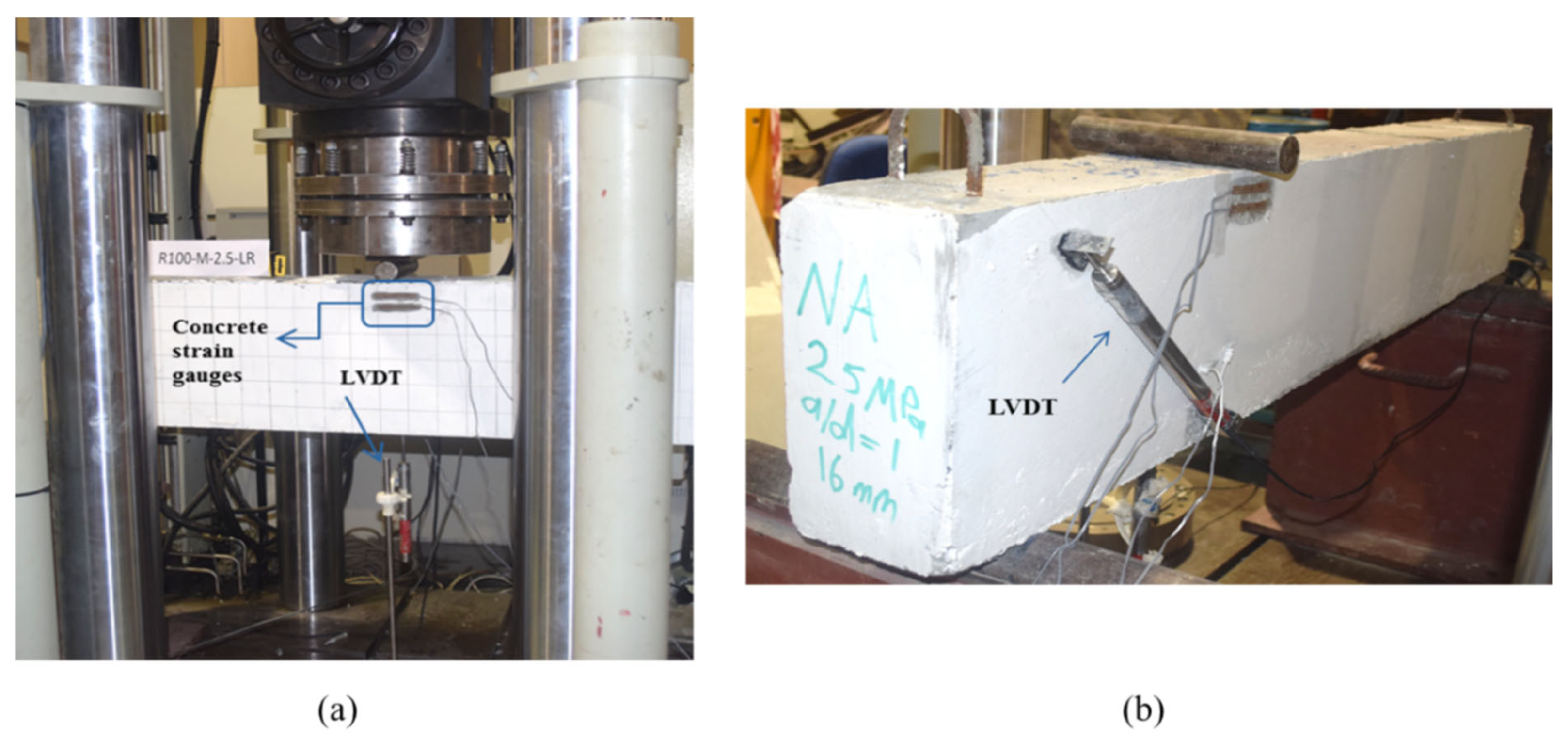
The beams were tested inside a 2500 kN capacity UTM in a displacement-controlled environment at a rate of 0.5 mm/min. Strain gauges were installed on the longitudinal bottom rebars and the surface of the concrete within the extreme compression flexural zone to record the tensile strains in the steel and compressive strains in the concrete at the location of maximum moment as the load was increased. The vertical deflection at the location of the applied load on the beams was measured by an LVDT that was mounted vertically at the bottom of the beams. Another LVDT was installed diagonally on the side of the tested beam within the region of the maximum shear to monitor the average crack width at that location. The test setup and instrumentation are summarized in Figure 3 and Figure 4.
The test program comprised 15 beams, of which 9 specimens were tested at = 1.15 (out of them there were three NA beams, three 50% RA beams, and three 100% RA beams) and 6 specimens at = 2.5 (of which there were two NA beams, two 50% RA beams, and two 100% RA beams). Within the first group, 6 beams had 25 MPa targeted concrete compressive strength (3 beams with = 0.0103 and 3 beams with = 0.016), and the remaining 3 beams had 35 MPa targets (with = 0.0103). In the second group, 3 beams had 25 MPa targeted concrete compressive strength (all with = 0.0103), and the remaining 3 beams had 35 MPa (all with = 0.0103). A summary of the experimental test program and the labeling of the fifteen beams is shown in Table 1. A special beam name designation was employed in the study, W–X–Y–Z, in which W was either NA for natural aggregate or RA for recycled aggregate, X was either L for low or M for medium , Y was 1 for = 1.15 or 2.5 for = 2.5, and finally Z was either LR for = 0.0103 or HR for = 0.016.
ASTM type I Ordinary Portland cement was used in all concrete mixes. Since this research focused on the influence of coarse aggregate on the shear strength of RC beams, all the fine aggregates that were used were natural and consisted of a combination of dune sand and crushed sand. In concrete mixes where the target compressive strength was 25 MPa, the percentages of dune sand and crushed sand were 35% and 65% of the total fine aggregate weight, respectively. In the mixes where 35 MPa was the target compressive strength, the dune sand was 40%, and the crushed sand was 60% of the total weight of the fine aggregate. The Fineness Modulus of the fine aggregate is presented in Table 2. In all mixes, two maximum coarse aggregate sizes were used, namely, 10 mm and 20 mm, of which the 10 mm aggregate constituted 35% and the 20 mm aggregate made up the remaining 65% of the coarse aggregate total weight. The source of the recycled coarse aggregate was old concrete demolition waste, which was processed by Beeah’s Waste Management facility [36] in Sharjah, UAE. The properties of both natural and recycled coarse aggregate are shown in Table 3. Details of the concrete mix proportions are presented in Table 4. The RA concrete mixes were prepared by directly replacing the NA coarse aggregate in the concrete mix with the same weight of RA. Everything else was kept the same to prevent introducing any additional parameters to the study.
To alleviate the workability problem associated with the high porosity of recycled concrete aggregate, an additional amount of super-plasticizer was added to the concrete mix to match the target slump without adding more water so that the water/cement ratio was kept constant for the RA beams and their corresponding NA beams. For each beam, two cylinders (300 mm × 150 mm) and two cubes (150 mm × 150 mm × 150 mm) were cast to determine the concrete compressive strength. At the time of beam testing, the average NA concrete cylinder compressive strength ranged from 30.55 to 33.9 MPa for the low target strength and 37.2 to 43.75 MPa for the medium target strength. The corresponding ranges for the 50% recycled aggregate concrete were 26.95–28.55 MPa and 35.55–36.0 MPa for the low and medium concrete target strengths, respectively. Likewise, the corresponding ranges for the concrete utilizing 100% recycled coarse aggregate were 29.3–31.85 MPa and 36.7–38.7 MPa for the low and medium concrete target strengths, respectively.
Three samples from each of the No. 16 and No. 20 longitudinal steel bars that were utilized in the beams to resist flexure were tested to determine their actual modulus of elasticity () and yielding strength (). The results showed that the mean value of was 200 GPa, and the value for the No. 16 and No. 20 bars averaged around 570 MPa.
3. Results
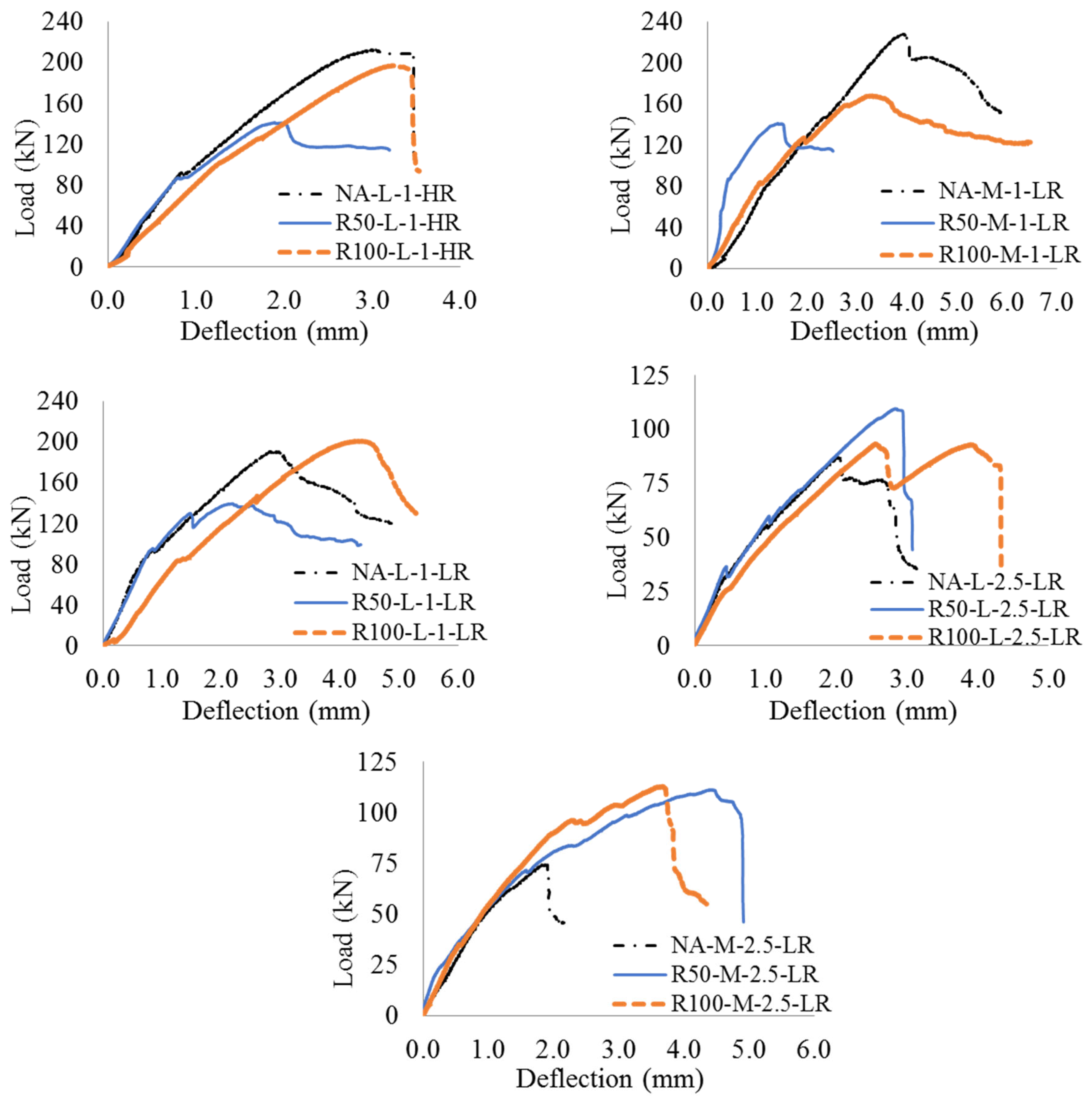
Each of the fifteen beams was subjected to an increasing vertical load until failure, which was defined when the load dropped by about 30% from its ultimate value. Figure 5 depicts the load–deflection relationships for the 15 tested beams. As expected, all load–displacement curves show a reduction in the stiffness of the beam just after cracking. The deflection at the instant of first crack varied depending on the percentage of the coarse aggregate in the concrete mix, the amount of longitudinal flexural steel, and the location of concentrated load along the beam. For the beams with = 1.15, the deflection at first crack was 1.0–1.5 mm, with the lower value associated with beams having natural coarse aggregate. For the beams with = 2.5, the deflection at first crack averaged around 0.5 mm for beams containing either natural or recycled coarse aggregate. The deflection at which the beams reached their maximum peak capacity for the case of the smaller ranged within 3–4 mm for the natural aggregate beams and 2–4 mm for recycled aggregate beams. The corresponding deflection at maximum capacity for the case of = 2.5 was within 2–5 mm for the natural aggregate beams and 2.5–4.5 mm for the RA beams. The observed residual strength beyond the ultimate capacity depended on the shear span-to-depth ratio. In general, beams that were tested at = 1.15 exhibited some residual strength following the attainment of the peak capacity, while beams that were tested at = 2.5 consistently failed in a brittle fashion with little warning prior to collapse.
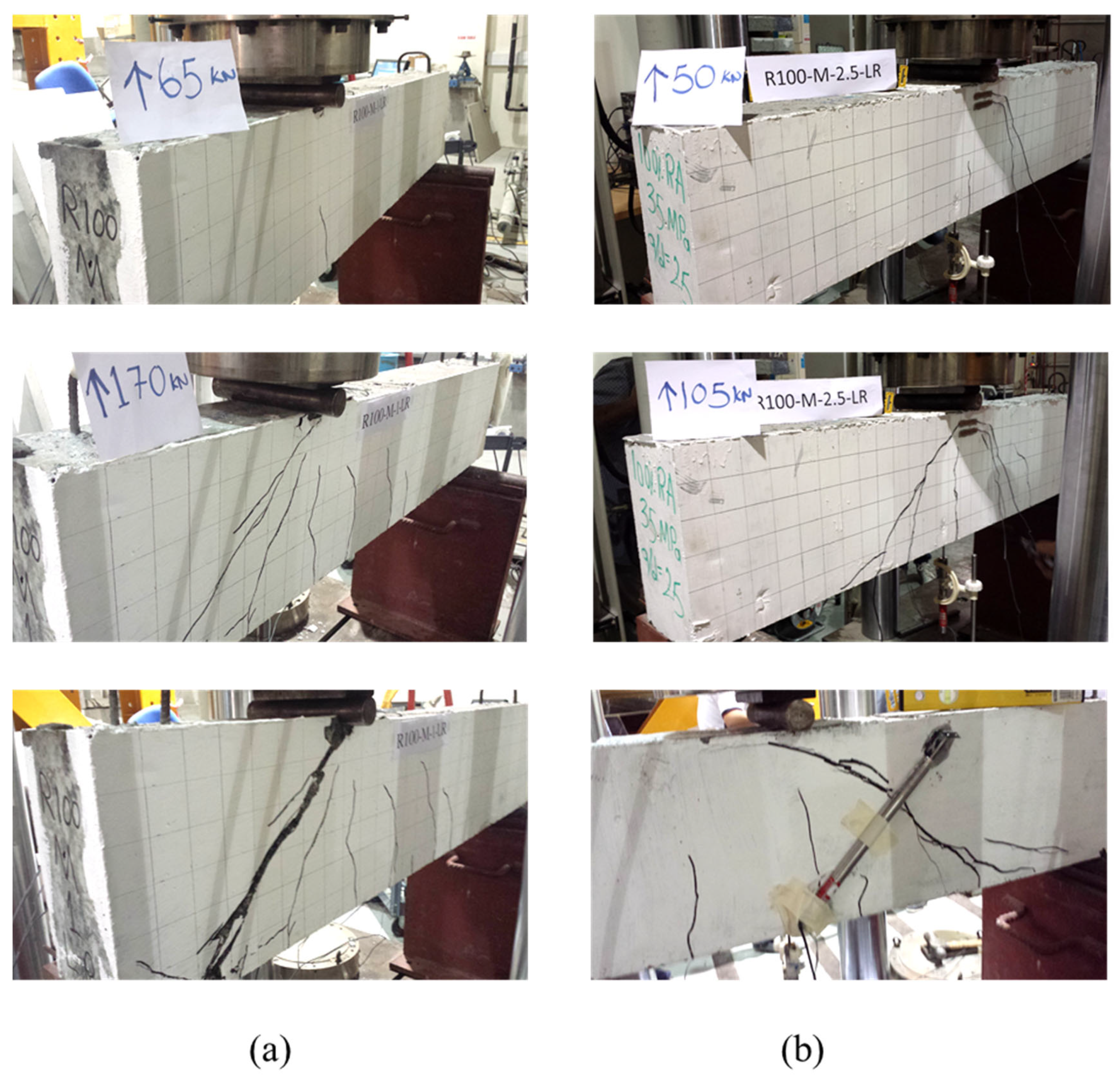
Figure 6 shows typical cracking patterns at various levels of load for 100% RA beams, R100-M-1-LR and R100-M-2.5-LR, that were tested at = 1.15 and 2.5, respectively. As expected, crack inclination was steeper in the beam with the smaller (deep beam behavior) compared to that with the higher (shallow beam behavior).
The shear strength provided by concrete () was calculated from the recorded ultimate load value () by the UTM and the shear diagram of a simply supported beam subjected to concentrated load using statics. For the beams that were tested at = 1.15, the critical shear was 76% of the applied load, while for the beams that were tested at = 2.5, the critical shear was 50% of the applied load. Table 5 presents the peak load and corresponding shear strength, along with the cylinder concrete compressive strength of each beam at the time of testing.
As expected and planned, the experimental results showed that all the beams failed in shear strength. As the load increased, flexural cracks started to appear on the surface of the beams in the vicinity of the loading point where the bending moment in the beam was highest. Gradually, more flexural cracks started to form away from that location, always vertically oriented. After that, shear cracks with angle inclinations appeared from the locations near the critical support towards the loading point within the instrumented region. These cracks propagated furthermore with the increase in the load until diagonal tension failure took place. In all the tested beams, the cause of the failure was a major diagonal crack followed by a drastic decrease in the beam capacity. For additional confirmation, the readings from the strain gauges confirmed that none of the longitudinal flexural steel reinforcement at the bottom of the beam reached a yielding state. Additionally, the concrete did not crush in compression due to flexure at the location of the applied load.
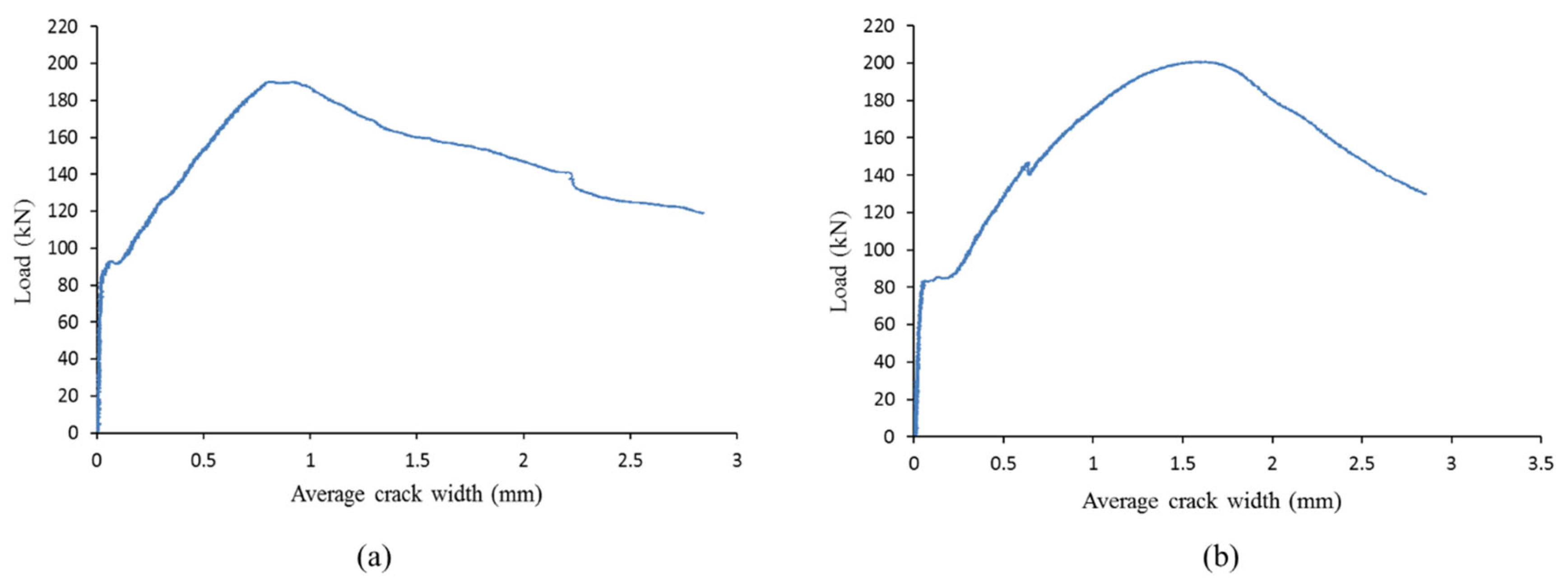
The average crack width due to shear was measured using an inclined LVDT positioned on the concrete surface between two points that were 339 mm apart and located at 30 mm from extreme top and bottom edges at an angle of 45° with the horizontal. Since the actual location and inclination angle of the major shear cracks are very difficult to predict prior to the test, the LVDTs were often not exactly perpendicular to the shear cracks; hence the measured crack width was notional, providing a reasonable idea about the crack size and can be used for comparative purposes. The recorded data by the LVDT showed that once shear cracks started to appear, the average crack width began to widen as the load increased. When the beam reached its full capacity and the shear failure mechanism took place, the measured average crack width kept widening while the beam gradually lost some of its capacity. The average crack width versus the applied load for beams NA-L-1-LR and R100-L-1-LR are shown in Figure 7.
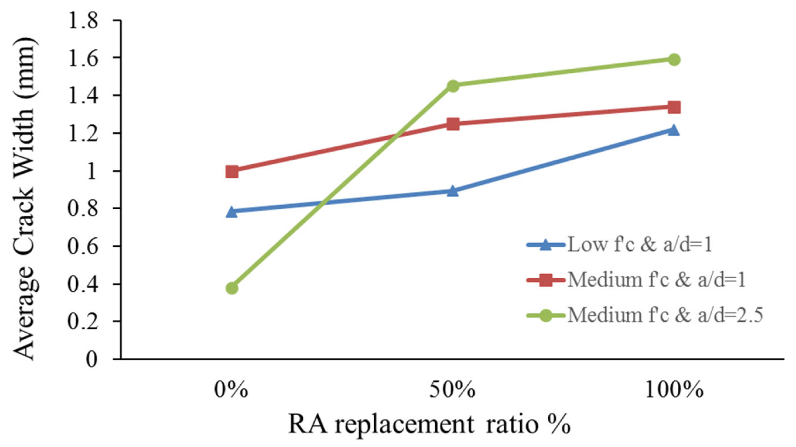
For most cases, it was found that as the amount of flexural reinforcement increased, the average crack width due to shear decreased due to the dowel action provided by the flexural reinforcement. This finding was observed mainly in beams made with concrete from either natural or 50% recycled coarse aggregate. Furthermore, it was noticed that as the recycled coarse aggregate replacement ratio increased, the average diagonal crack width also increased for the considered concrete strengths and shear span-to-depth ratios, as shown in Figure 8.
As shown in Table 6, the angle of inclination of the major shear crack from a horizontal datum at the ultimate for all tested beams varied between 34° and 60°. For the beams with a small shear span-to depth ratio (), the average angle of inclination of the shear crack was about 45.3°. On the other hand, the average angle of inclination of the shear crack was about 38.3° for the beams with a large shear span-to-depth ratio (). Furthermore, the tested beams with a high effective steel reinforcement ratio ( = 1.6%) showed larger angles (ranging between 50° and 60°) than their counterpart with a low reinforcement ratio ( = 1.03%), which was 40.8° for the case of . Additionally, RC beams made with NA had somewhat steeper angles of shear cracks than those made with RA. For the case, the average angle of the major crack increased with the increase of the coarse aggregate replacement ratio. There was no consistent trend in the average inclination angle for the case of . However, beams made with NA had slightly steeper angles of shear cracks than those made with RA when .
Furthermore, the results in Table 7 show, as expected, that the loads at first (vertical) flexural crack formation for the beams with low ratios were higher than the corresponding loads for beams with high ratios. This was due to the fact that as the applied load moved away from mid-span, the resulting bending moment decreased; hence, a larger load was needed to generate the cracking moment. As for the load at initiation of (diagonal) shear crack, results of the experimental tests demonstrated that as the load moved towards mid-span ), the load required to cause shear failure was decreased due to presence of significant flexure together with shear force in the region near the mid-span.
4. Discussion
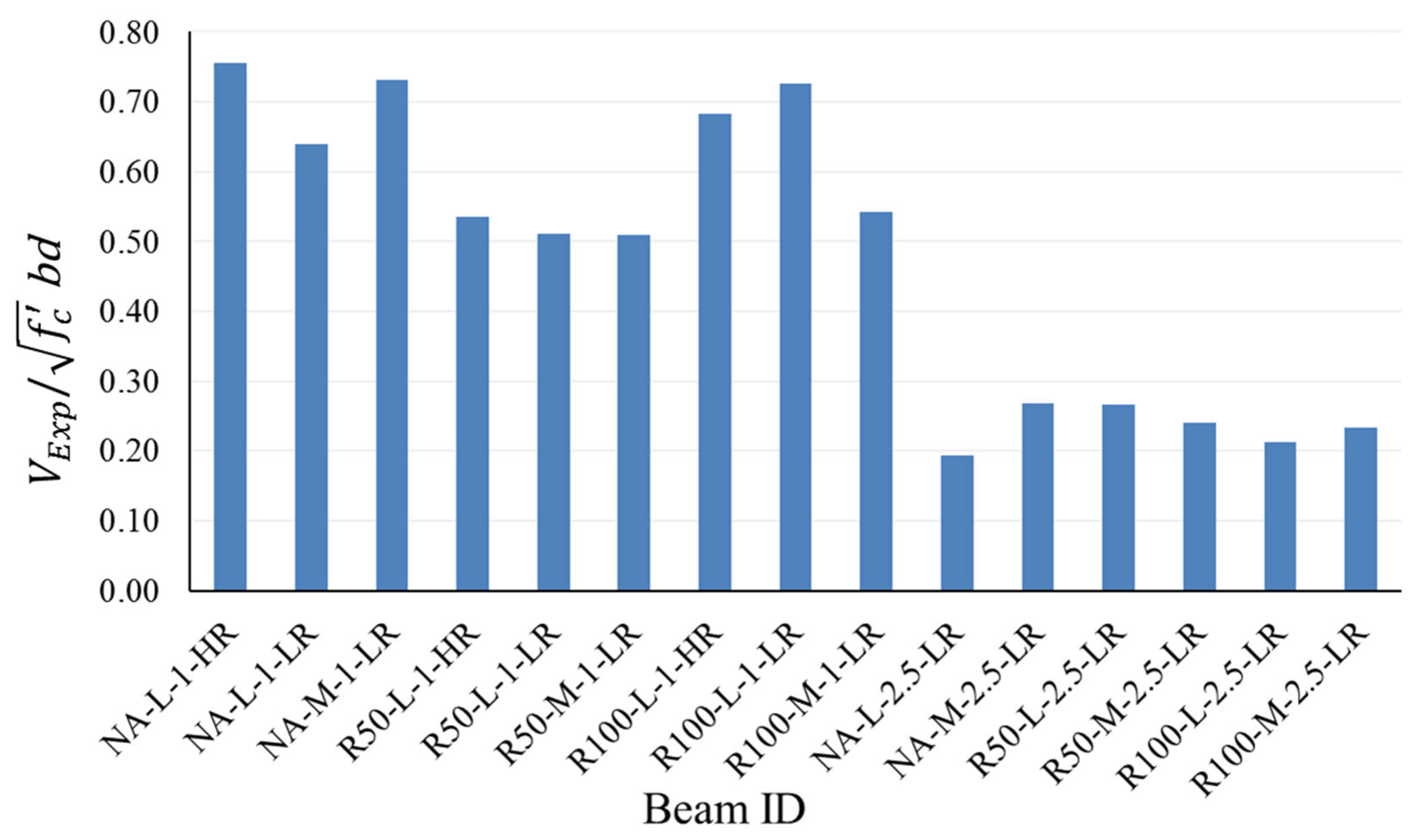
The maximum shear force that the beam specimens were able to support during the experiments represents the shear strength, (N). To study the effect of the coarse aggregate replacement ratio, shear span-to-depth ratio, concrete compressive strength, and effective longitudinal steel reinforcement ratio on shear strength, the obtained shear strength from the tests was normalized by dividing it by the quantity . The reason for the normalization is to reduce the effect of variations in concrete strength, and small deviations in the effective depth due to using different rebar sizes in the specimens. Figure 9 shows the normalized shear strength for all the tested beams. A discussion of the experimentally obtained results follows.
4.1. Effect of RA Replacement Ratio
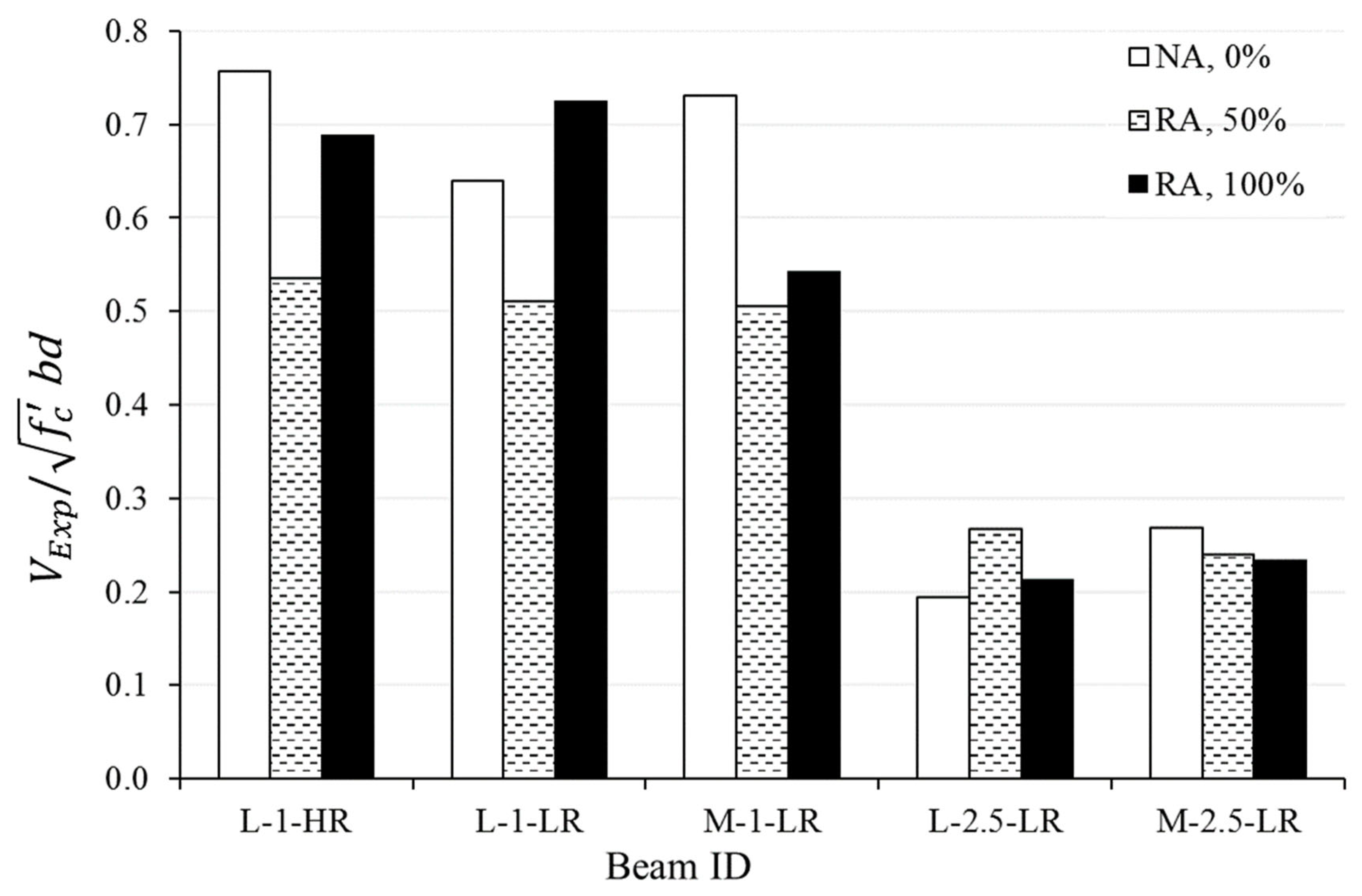
Figure 10 shows the impact of the recycled coarse aggregate replacement ratio on the normalized shear strength values of the considered beams. In the figure, the first, second, and third terms in notation on the x-axis represent, respectively, the characteristics of (low or medium), (1.15 or 2.5), and (low or high reinforcement). In general, the results indicated that the use of recycled coarse aggregate in beams did not greatly compromise the shear strength of the concrete, especially if the aggregate replacement ratio was 100%. Furthermore, all the recycled aggregate concrete beams that were tested at = 2.5 showed close normalized shear strength values to their counterparts that were made with natural aggregate. On the other, the three beams with 50% RA, which were tested at = 1.15, exhibited inferior shear strength by an average of 27% when compared with their NA complements. It is noticeable that the 50% RA beams had very close normalized shear strength for the same ratio, irrespective of the concrete strength, with slight reduction in the shear strength of the beams with lower compared to the beam with higher . As for the beams with 100% RA, the normalized shear strength of such beams was always higher than their equivalents with 50% RA by an average of 26%. For the combined results of both ratios, the average shear strength reduction in the 100% RA with respect to the NA beams was 5% only, keeping in mind that there were two cases in which the strength of the 100% RA beams exceeded that of the corresponding NA beams (L-1-LR, L-2.5-LR).
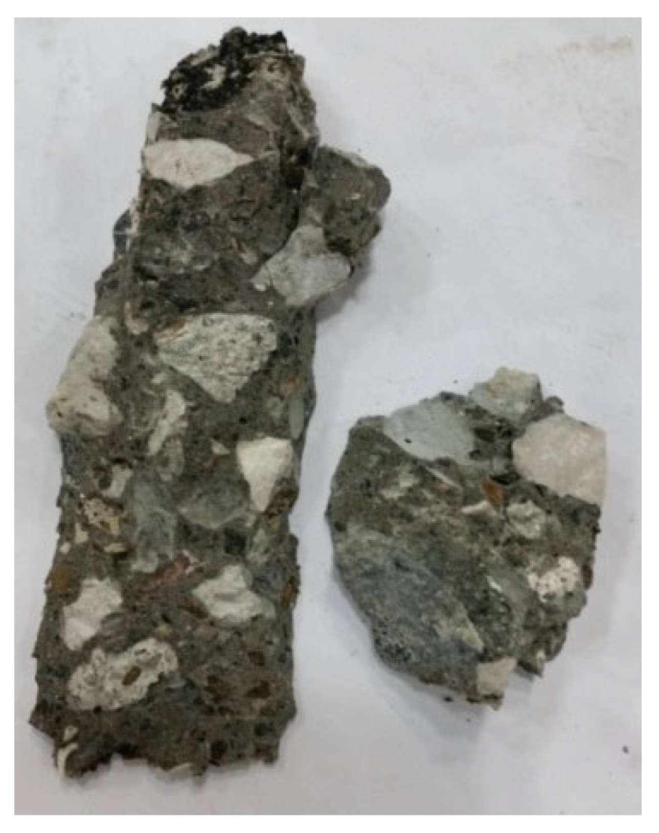
The observed increase in shear capacity of the 100% RA beams compared to the 50% RA beams when = 1.15 and the closeness of the results of both when = 2.5 can be attributed to the rough and jagged surfaces of the recycled aggregates, causing them to have better interlock with each other and bonding with the mortar around them. A similar explanation was proposed by Ignjatović et al. [37]. Moreover, it was observed that the shear plane for the 100% RA went through the recycled coarse aggregate, not around its surface, as shown in Figure 11. This proves that the RA had good bonding characteristics with the paste, although they were not as strong as the NA, which were made from limestone. This study showed that the presence of rounded natural aggregate together with pointed recycled aggregate in the same mix, i.e., concrete with 50% RA, might not give as high a shear strength as a mix with 100% natural aggregate or 100% recycled aggregate, especially for lower ratios.
With regard to the effect of the RA replacement ratio on ductility, the relevant load-deflection plots in Figure 5 indicate that the beams with 50% RA generally reached their peak shear strength at much lower deflection than the beams with NA or 100% RA when = 1.15, indicating lower ductility than later beams. As for the case of = 2.5, beams with 50% RA attained their maximum shear strength at deflections comparable to the beams containing NA or 100% RA, demonstrating similar ductility to those beams.
4.2. Effect of Shear Span-to-Depth Ratio
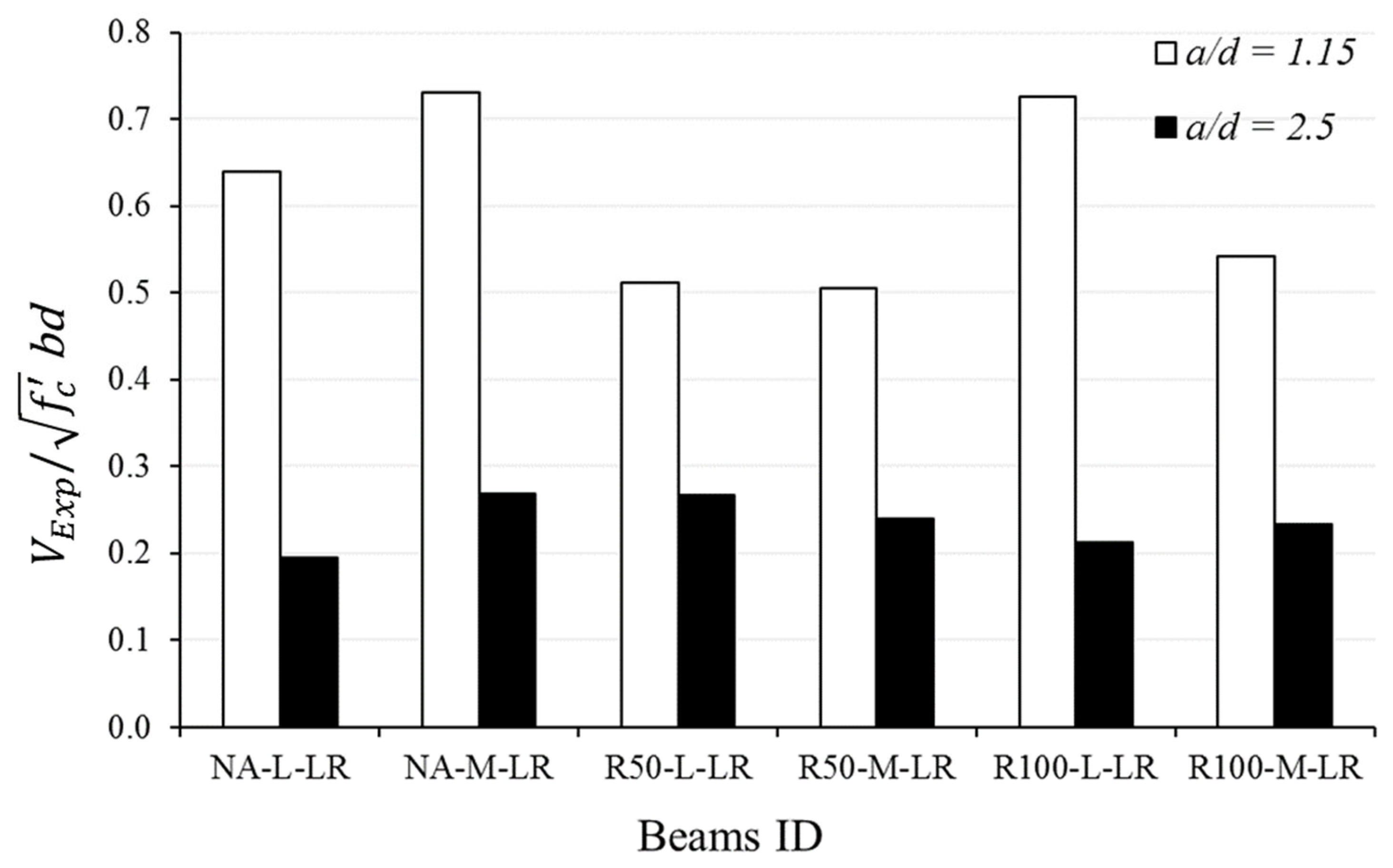
Figure 12 depicts the effect of the shear span-to-depth ratio on shear strength by presenting the normalized shear capacities of two similar beams in all aspects except for the () ratio. The test results confirmed that the shear capacity of deep beams (small ) is much larger than that of shallow beams (large ). Similar to the shear behavior of beams containing NA, the beams that were made with RA showed that the shear strength corresponding to = 1.15 can be 2 to 3 times the shear strength corresponding to = 2.5, with the lower bound dominated by the beams containing 50% RA. The enhanced shear strength for beams tested at small when compared with that at large is mainly due to the arching action and is recognized by the strut-and-tie modeling provisions of deep beams in structural concrete design codes. As expected, all the beams that were tested at lower ratio demonstrated higher stiffness than the corresponding beams that were tested at higher ratio by a factor of 2.5–4.5, as exhibited in Figure 5.
4.3. Effect of Concrete Strength
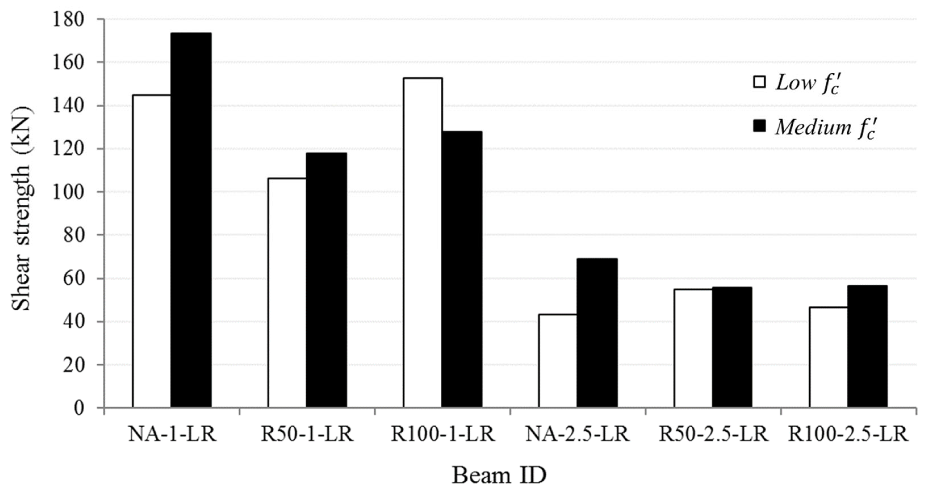
Two vales of were targeted in this study, namely, 25 MPa (referred to as low or L) and 35 MPa (referred to as medium or M). For the beams that were made with low strength concrete, the average compressive cylinder strength was 32.48 MPa for the concrete with NA, 27.82 MPa for the concrete with 50% RA, and 30.98 MPa for the concrete with 100% RA. The corresponding averages for the target medium concrete compressive strength were 40.48 MPa, 35.78 MPa, and 37.70 MPa for the concrete made with NA, 50% RA, and 100% RA, respectively.
The contribution of concrete compressive strength to the shear capacity has been studied extensively in the literature. Higher compressive strength forces the shear plane to go through the aggregates, not through the mortar, thus increasing the shear strength of the concrete member. Additionally, the concrete tensile strength is highly correlated with the compressive strength, which directly impacts the shear strength, since collapse due to shear is often a result of diagonal tension failure. In Figure 13, the shear strength of the tested specimens without normalization is presented for each pair of beams having similar parameters but different concrete strengths. Except for the case of the two beams that were made with 100% RA and tested at = 1.15, all other pairs of beams demonstrated larger shear capacity for the beams with higher concrete strength. The reason why those two beams did not follow the same trend could be attributed the fact that the beam R100-M-1-LR was tested at the age of 5 weeks, whereas its counterpart, beam R100-L-1-LR, was tested at a much later stage due to logistical issues. Careful examination of the results showed that there is no clear correlation between shear strength provided by concrete and for the recycled aggregate beams. This finding agrees with conclusions of Rahal and Alrefaei [22].
4.4. Effect of Longitudinal Flexural Reinforcement
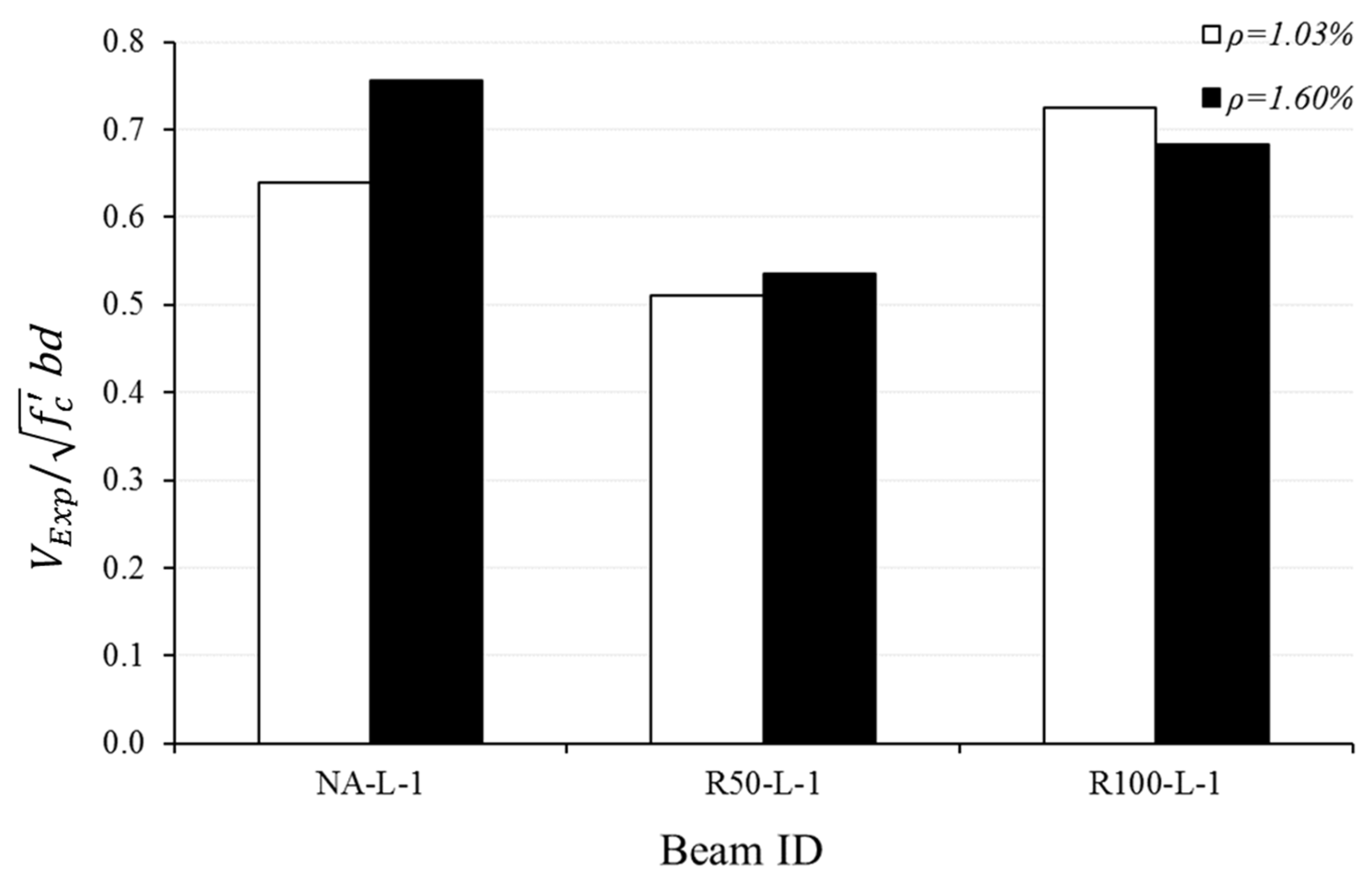
All beams in the study contained longitudinal reinforcement in the flexural tension zone without stirrups in the critical shear region. Three beams were cast with a low reinforcement (LR) ratio consisting of two No. 12 bars at the bottom (), and three counterpart beams were cast with a high reinforcement (HR) ratio consisting of two No. 16 bars at the bottom (). All the beams had low target concrete compressive strength () and = 1.15. Figure 14 compares the normalized shear strength of each pair of beams, where one has low and the other has high .
The result in the figure confirms the positive impact of longitudinal reinforcement on shear strength of beams containing NA, since an increase in by about 60% resulted in about a 17% increase in shear capacity. However, the effect of enhanced dowel action due an increase in in the beams containing RA was less dominant. The 60% increase in resulted in only a 4% increase in shear strength for the beam containing 50% RA and 6% decrease in strength for the one containing 100% RA.
For the dowel action to be effective, the modulus of elasticity of concrete should be large in order to resist the local deformation of the steel rebar bearing against the concrete. Inspection of the average stiffness of the members on the ascending part of their load–deflection relationships in Figure 5 showed that the average stiffness of the NA concrete beams (k = 125 kN/m) is larger than those of the 50% RA (k = 110 kN/m) and 100% RA (k = 90 kN/m) concrete beams, which is mainly due to the impact of the modulus of elasticity of the concrete. This can explain the reduced influence of the longitudinal reinforcement ratio on the shear strength of concrete beams made with 100% recycled aggregate.
4.5. Experimental versus Predicted Shear Strength
Numerous studies have been published in the literature to predict the shear strength behavior of reinforced concrete members. Unlike flexure, the shear design guidelines of RC members are often empirically based due to the complexity of the problem. The shear behavior can be influenced by many factors, such as the depth of the member, concrete compressive strength, nature of the aggregate and shear span-to-depth ratio (), dowel action of the flexural reinforcement, presence of axial load, etc.
In this study, the experimental results of all beams were compared to the predicted shear strength obtained by the provision of the ACI 318-14 code [16], the ACI-318-19 code [17], and the strut-and-tie simplified model developed by Matamoros and Wong [18].
The shear strength provided by concrete for shallow beams not containing stirrups and not subjected to axial load in the ACI 318-14 code is given by
The corresponding equation for beams not subjected to axial load in the ACI 318-19 is given by
where is the longitudinal reinforcement ratio, is the concrete compressive strength (MPa), is the light-weight concrete factor (=1 for normal weight concrete), is the effective depth of flexural steel reinforcement from the extreme compression edge (mm), is the narrowest width of the beam (mm), and is the size effect factor. The size effect factor accounts for the thickness of the member, which is a function of the member effective depth d (mm):
For the considered beams in the experimental program, b = 150 mm and d = 259 mm for beams with = 1.03%, and d = 257 mm for beams with = 1.6%. For beams subjected to loads at mid-span, Vu d/Mu = d/a = d/650, and for beams subjected to loads near the support, = d/a = d/300.
For beams without transverse reinforcement, the simplified strut-and-tie model proposed by Matamoros and Wong [18] predicts the strength of the compressive strut based on the geometry of the node at the support by
where is the width of the base plate (mm), is twice the distance between the centroid of the main reinforcement and the bottom of the beam (mm), b is the width of the web (mm), and the strut inclination angle can be approximated by (d/a). The maximum concentrated load that can be supported by the simple beam is obtained from
in which is a coefficient that relates the applied force to the strength of the strut. A lower bound on is obtained as a function of the shear span-to-depth ratio from
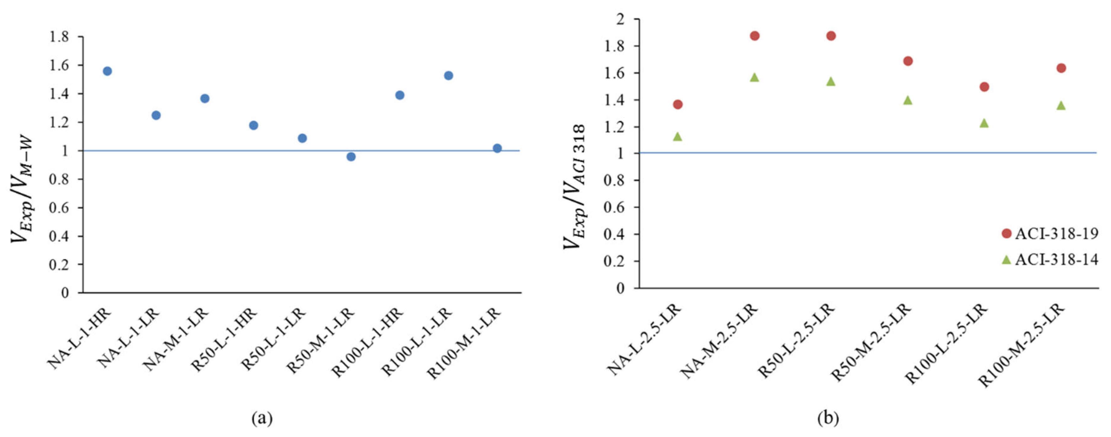
The predict values of shear strength of the beams from the old and new versions of the ACI 318 code and from the simplified strut-and-tie model are presented in Table 8. Since the ACI 318 code provisions for shear strength are applicable to > 2, the predicted results for the six beams that were tested at = 2.5 are based on the ACI code, and the prediction of the nine remaining beams that were tested at = 1.15 are based on Matamoros and Wong’s approach.
The experimental-to-theoretical shear strength ratios of the 15 beams are presented in Figure 15. Practically, all predictions regardless of the considered parameters and the prediction method were overconservative. For the beams that were tested at = 1.15, the simplified strut-and-tie-based model proposed Matamoros and Wong under-estimated the shear strength by an average of 26%, with a coefficient of variation equal to 16.2%. For the beams that were tested at = 2.5, the ACI 318-14 and 318-19 code versions under-estimated the shear strength by averages of 37% and 66%, respectively. The corresponding coefficients of variation for the code predictions were 11.5% and 11.3%, respectively.
5. Conclusions
This research studied the shear capacity and performance of RC beams made with recycled coarse aggregate without stirrups. Accordingly, fifteen RC beams were constructed and tested under a UTM machine to investigate their load–deflection behavior. Three levels of RA replacement ratio were utilized, namely, 0%, 50%, and 100%. The key parameters that affected the shear strength and behavior of the specimens were also studied. Results of the study led to the following conclusions:
- All the 50% and 100% RA concrete beams that were tested at a/d = 2.5 showed comparable shear strengths to their NA counterparts. For the a/d = 1.15 ratio, the 100% RA beams exhibited higher shear strength compared to their 50% RA corresponding beams by an average of 26% and a reduction in strength by 5% on average when compared with the NA beams. The 50% RA beams that were tested at the same a/d ratio displayed 27% lower shear strength than their NA counterparts.
- When loaded at a/d = 1.15, beams with 50% RA generally reached their peak shear strength at lower deflection than their corresponding NA beams or beams containing 100% RA. As for the case of a/d = 2.5, all RA beams attained their maximum shear strength at comparable deflections to their corresponding NA beams.
- An increase in the amount of flexural reinforcement and a decrease in the RA replacement ratio resulted in a reduction in the average diagonal crack width within the shear-critical regions.
- The effect of the shear span-to-depth ratio on shear strength was similar among the RA and NA beams. The 50% and 100% RA beams that were tested at a/d = 1.15 exhibited two to three times higher shear strength and 2.5–4.5 higher stiffness than corresponding ones that were tested at a/d = 2.5, with the lower bound dominated by the beams containing 50% RA.
- Higher concrete compressive strength generally increased the shear strength provided by concrete in all beams. However, there was no strong correlation between the square-root of the concrete compressive strength and shear strength of the RA beams.
- The effect of the flexural steel reinforcement ratio was not as significant in the beams made with RA as in those made with natural aggregate. An increase of about 60% in resulted in a change of just 4–6% in the shear strength of RA beams compared to a 17% increase in NA beams.
- The shear strength of beams without stirrups can be reasonable predicted by the ACI 318 code when a/d > 2 (shallow beams) and by Matamoros and Wong’s pseudo strut-and-tie method [18] when a/d < 2.
Possible areas for future research on recycled concrete include a more in-depth analysis of the factors influencing its shear strength and ductility, as well as an evaluation of the economic benefits of using recycled concrete, including cost savings and reduced environmental impacts. It may also be useful to examine the shear behavior of reinforced concrete beams made with alternative coarse aggregate replacement materials, such as waste lathe, tire, rubber tree seed shells, and coconut fibers.
Author Contributions
A.M.S. and S.W.T. conceived of the presented idea. A.M.S. and S.W.T. designed and planned the experimental program. A.M.S. carried out the experimental program. S.W.T. supervised the experimental work. A.M.S. performed the analytical investigation and performed the numerical calculations. Both A.M.S. and S.W.T. discussed the results and proposed the computational adjustment. A.M.S. took the lead in writing the manuscript, and S.W.T. provided critical feedback and helped shape the final version. All authors have read and agreed to the published version of the manuscript.
Funding
This research received no external funding.
Data Availability Statement
The datasets used and/or analyzed during the current study are available from the corresponding author upon reasonable request.
Acknowledgments
The authors would like to thank Beeah Group in Sharjah, United Arab Emirates, for providing the recycled coarse aggregate that was used in the study. The help of Senior Lab Instructor Engineer Arshi Faridi and Lab Technician Engineer Mohammad Ansari in conducting the experimental tests in the laboratory is much appreciated.
Conflicts of Interest
The authors declare no conflict of interest.
References
- Van Damme, H. Concrete material science: Past, present, and future innovations. Cem. Concr. Res. 2018, 112, 5–24. [Google Scholar] [CrossRef]
- De Brito, J.; Saikia, N. Recycled Aggregate in Concrete: Use of Industrial, Construction and Demolition Waste; Springer Science & Business Media: Berlin/Heidelberg, Germany, 2012. [Google Scholar]
- Trindade, J.; Garcia, S.; Fonseca, G. Experimental Study of Direct Shear in Concrete with Recycled Aggregate. ACI Struct. J. 2020, 117, 233–243. [Google Scholar] [CrossRef]
- Sheen, Y.-N.; Wang, H.-Y.; Juang, Y.-P.; Le, D.-H. Assessment on the engineering properties of ready-mixed concrete using recycled aggregates. Constr. Build. Mater. 2013, 45, 298–305. [Google Scholar] [CrossRef]
- Radonjanin, V.; Malešev, M.; Marinković, S.; Al Malty, A.E.S. Green recycled aggregate concrete. Constr. Build. Mater. 2013, 47, 1503–1511. [Google Scholar] [CrossRef]
- Corinaldesi, V.; Moriconi, G. Influence of mineral additions on the performance of 100% recycled aggregate concrete. Constr. Build. Mater. 2009, 23, 2869–2876. [Google Scholar] [CrossRef]
- Etxeberria, M.; Vázquez, E.; Marí, A.; Barra, M. Influence of amount of recycled coarse aggregates and production process on properties of recycled aggregate concrete. Cem. Concr. Res. 2007, 37, 735–742. [Google Scholar] [CrossRef]
- Corinaldesi, V. Mechanical and elastic behaviour of concretes made of recycled-concrete coarse aggregates. Constr. Build. Mater. 2010, 24, 1616–1620. [Google Scholar] [CrossRef]
- Abdelfatah, A.S.; Tabsh, S.W. Review of research on and implementation of recycled concrete aggregate in the GCC. Adv. Civ. Eng. 2011, 2011, 567924. [Google Scholar] [CrossRef]
- Karalar, M.; Bilir, T.; Çavuşlu, M.; Özkiliç, Y.O.; Sabri Sabri, M.M. Use of recycled coal bottom ash in reinforced concrete beams as replacement for aggregate. Front. Mater. 2022, 9, 1064604. [Google Scholar] [CrossRef]
- Çelik, A.İ.; Özkılıç, Y.O.; Zeybek, Ö.; Karalar, M.; Qaidi, S.; Ahmad, J.; Burduhos-Nergis, D.-D.; Bejinariu, C. Mechanical Behavior of Crushed Waste Glass as Replacement of Aggregates. Materials 2022, 15, 8093. [Google Scholar] [CrossRef]
- Qaidi, S.; Najm, H.M.; Abed, S.M.; Özkılıç, Y.O.; Al Dughaishi, H.; Alosta, M.; Sabri Sabri, M.M.; Alkhatib, F.; Milad, A. Concrete Containing Waste Glass as an Environmentally Friendly Aggregate: A Review on Fresh and Mechanical Characteristics. Materials 2022, 15, 6222. [Google Scholar] [CrossRef]
- Karalar, M.; Özkılıç, Y.O.; Aksoylu, C.; Sabri, M.M.S.; Alexey, N.B.; Sergey, A.S.; Evgenii, M.S. Flexural behavior of reinforced concrete beams using waste marble powder towards application of sustainable concrete. Front. Mater. 2022, 9, 1068791. [Google Scholar] [CrossRef]
- Çelik, A.I.; Özkılıç, Y.O.; Zeybek, Ö.; Özdöner, N.; Tayeh, B.A. Performance Assessment of Fiber-Reinforced Concrete Produced with Waste Lathe Fibers. Sustainability 2022, 14, 11817. [Google Scholar] [CrossRef]
- Zeybek, Ö.; Özkılıç, Y.O.; Çelik, A.İ.; Deifalla, A.F.; Ahmad, M.; Sabri Sabri, M.M. Performance evaluation of fiber-reinforced concrete produced with steel fibers extracted from waste tire. Front. Mater. 2022, 9, 692. [Google Scholar] [CrossRef]
- González-Fonteboa, B.; Martínez-Abella, F. Shear strength of recycled concrete beams. Constr. Build. Mater. 2007, 21, 887–893. [Google Scholar] [CrossRef]
- Yun, H.-D.; Choi, W.-C. Shear strength of reinforced recycled aggregate concrete beams without shear reinforcements. J. Civ. Eng. Manag. 2016, 23, 76–84. [Google Scholar] [CrossRef]
- Rahal, K.; Alrefaei, Y. The shear strength of 50 MPa concrete beams made using recycled concrete coarse aggregates. ISEC Press 2015, 3, 601–605. [Google Scholar] [CrossRef]
- Rahal, K.N.; Alrefaei, Y.T. Shear strength of longitudinally reinforced recycled aggregate concrete beams. Eng. Struct. 2017, 145, 273–282. [Google Scholar] [CrossRef]
- Ajdukiewicz, A.B.; Kliszczewicz, A.T. Comparative Tests of Beams and Columns Made of Recycled Aggregate Concrete and Natural Aggregate Concrete. J. Adv. Concr. Technol. 2007, 5, 259–273. [Google Scholar] [CrossRef] [Green Version]
- Knaack, A.M.; Kurama, Y.C. Behavior of Reinforced Concrete Beams with Recycled Concrete Coarse Aggregates. J. Struct. Eng. 2015, 141, 401–409. [Google Scholar] [CrossRef]
- Fathifazl, G.; Razaqpur, A.G.; Isgor, O.B.; Abbas, A.; Fournier, B.; Foo, S. Shear strength of reinforced recycled concrete beams without stirrups. Mag. Concr. Res. 2009, 61, 477–490. [Google Scholar] [CrossRef]
- Lian, O.C.; Wee, L.S.; Masrom, M.; Hua, G.C. Experimental Study on Shear Behaviour of High Strength Reinforced Recycled Concrete Beam. Pertanika J. Sci. Technol. 2013, 21, 601–610. [Google Scholar]
- Kim, S.-W.; Jeong, C.-Y.; Lee, J.-S.; Kim, K.-H. Size Effect in Shear Failure of Reinforced Concrete Beams with Recycled Aggregate. J. Asian Archit. Build. Eng. 2013, 12, 323–330. [Google Scholar] [CrossRef]
- Deng, Z.H.; Liao, Y.; Lou Meng, C.; Yang, H.F. Experimental Study on the Shearing Property of Equal Strength Recycled Coarse Aggregate Concrete. Appl. Mech. Mater. 2013, 357–360, 1420–1427. [Google Scholar] [CrossRef]
- Arezoumandi, M.; Smith, A.; Volz, J.S.; Khayat, K.H. An experimental study on shear strength of reinforced concrete beams with 100% recycled concrete aggregate. Constr. Build. Mater. 2014, 53, 612–620. [Google Scholar] [CrossRef]
- Arezoumandi, M.; Drury, J.; Volz, J.S.; Khayat, K.H. Effect of Recycled Concrete Aggregate Replacement Level on Shear Strength of Reinforced Concrete Beams. ACI Mater. J. 2015, 112, 559–568. [Google Scholar] [CrossRef]
- Schubert, S.; Hoffmann, C.; Leemann, A.; Moser, K.; Motavalli, M. Recycled aggregate concrete: Experimental shear resistance of slabs without shear reinforcement. Eng. Struct. 2012, 41, 490–497. [Google Scholar] [CrossRef]
- Deresa, S.T.; Xu, J.; Demartino, C.; Heo, Y.; Li, Z.; Xiao, Y. A review of experimental results on structural performance of reinforced recycled aggregate concrete beams and columns. Adv. Struct. Eng. 2020, 23, 3351–3369. [Google Scholar] [CrossRef]
- Pacheco, J.N.; de Brito, J.; Chastre, C.; Evangelista, L. Uncertainty of shear resistance models: Influence of recycled concrete aggregate on beams with and without shear reinforcement. Eng. Struct. 2020, 204, 109905. [Google Scholar] [CrossRef]
- Tošić, N.; Marinković, S.; Ignjatović, I. A database on flexural and shear strength of reinforced recycled aggregate concrete beams and comparison to Eurocode 2 predictions. Constr. Build. Mater. 2016, 127, 932–944. [Google Scholar] [CrossRef]
- Pradhan, S.; Kumar, S.; Barai, S.V. Shear performance of recycled aggregate concrete beams: An insight for design aspects. Constr. Build. Mater. 2018, 178, 593–611. [Google Scholar] [CrossRef]
- American Concrete Institute ACI318 Committee. Building Code Requirements for Structural Concrete (ACI 318-14): An ACI Standard; Commentary on Building Code Requirements for Structural Concrete (ACI 318R-14); ACI Committee: Farmington Hills, MI, USA, 2014. [Google Scholar]
- American Concrete Institute ACI318 Committee. Building Code Requirements for Structural Concrete ACI 318-19 and Commentary 318R-19; ACI Committee: Farmington Hills, MI, USA, 2019. [Google Scholar]
- Matamoros, A.B.; Wong, K.H. Design of simply supported deep beams using strut-and-tie models. ACI Struct. J. 2003, 100, 704–712. [Google Scholar]
- Leading Environmental Management Company in UAE: Bee’ah. Available online: https://beeah.ae/en (accessed on 7 July 2021).
- Ignjatović, I.S.; Marinković, S.B.; Tošić, N. Shear behaviour of recycled aggregate concrete beams with and without shear reinforcement. Eng. Struct. 2017, 141, 386–401. [Google Scholar] [CrossRef]
Figure 1.
Dimensions and reinforcement details of the test’s beams.

Figure 2.
Steel reinforcement steel cage: (a)
= 2.5, (b) = 1.15.

Figure 3.
Schematic diagram showing the test setup using the UTM.

Figure 4.
Instrumentation of the specimen: (a) strain gauges on concrete and vertical LVDT, (b) diagonally mounted LVDT.
Figure 4.
Instrumentation of the specimen: (a) strain gauges on concrete and vertical LVDT, (b) diagonally mounted LVDT.

Figure 5.
Load–deflection relationships for the 15 tested beams.

Figure 6.
Cracking pattern for beams containing 100% recycled aggregate: (a) = 1.15, (b) = 2.5.

Figure 7.
Average crack width versus load: (a) beam NA-L-1-LR, and (b) beam R100-L-1-LR.

Figure 8.
Crack width versus percentage of recycled aggregate ratio for low .

Figure 9.
Normalized shear strength of the tested beams.

Figure 10.
Effect of RA replacement ratio on shear capacity.

Figure 11.
Samples taken from beam made with 100% RA.

Figure 12.
Effect of span-to-depth ratio on the normalized shear strength.

Figure 13.
Effect of on the shear strength.

Figure 14.
Effect of longitudinal reinforcement ratio on the normalized shear strength.

Figure 15.
-to-theoretical shear strength ratios: (a) for = 1.15, (b) for = 2.5.


Table 1.
Beam characteristics and notations.
| Serial No. | Beam ID | (MPa) | % Coarse Aggregate Replacement | ||
|---|---|---|---|---|---|
| 1 | NA-L-1-HR | 1.15 | 25 | 0 | 0.016 |
| 2 | NA-L-1-LR | 25 | 0 | 0.0103 | |
| 3 | NA-M-1-LR | 35 | 0 | 0.0103 | |
| 4 | R50-L-1-HR | 25 | 50 | 0.016 | |
| 5 | R50-L-1-LR | 25 | 50 | 0.0103 | |
| 6 | R50-M-1-LR | 35 | 50 | 0.0103 | |
| 7 | R100-L-1-HR | 25 | 100 | 0.016 | |
| 8 | R100-L-1-LR | 25 | 100 | 0.0103 | |
| 9 | R100-M-1-LR | 35 | 100 | 0.0103 | |
| 10 | NA-L-2.5-LR | 2.50 | 25 | 0 | 0.0103 |
| 11 | NA-M-2.5-LR | 35 | 0 | 0.0103 | |
| 12 | R50-L-2.5-LR | 25 | 50 | 0.0103 | |
| 13 | R50-M-2.5-LR | 35 | 50 | 0.0103 | |
| 14 | R100-L-2.5-LR | 25 | 100 | 0.0103 | |
| 15 | R100-M-2.5-LR | 35 | 100 | 0.0103 |
Table 2.
Fineness Modulus of the natural fine aggregate.
| Type of Aggregate | Dune Sand | Crushed Sand | Combined Dune and Crushed Sand |
|---|---|---|---|
| F.M | 0.74 | 3.51 | 2.03 |
Table 3.
Coarse aggregate properties.
| Aggregate Type | Size (mm) | Bulk S.G. | Apparent S.G. | Absorption | Moisture | LA Abrasion | Crushing Value |
|---|---|---|---|---|---|---|---|
| Natural | 10 | 2.84 | 2.7 | 3.99 | 1.18 | 24 | 19.1 |
| 20 | 2.64 | 2.73 | 1.16 | 0.78 | 18.6 | 19.8 | |
| Recycled | 10 | 2.36 | 2.72 | 5.61 | 1 | 27.3 | 21.5 |
| 20 | 2.4 | 2.71 | 4.72 | 1.83 | 31.9 | 24.1 |
Table 4.
Concrete mix proportions.
| Mix | Crushed Sand (kg) | Dune Sand (Kg) | NA Coarse Aggregate (kg) | RA Coarse Aggregate (kg) | Cement (kg) | Water (kg) | ||
|---|---|---|---|---|---|---|---|---|
| 10 mm | 20 mm | 10 mm | 20 mm | |||||
| NA-L | 579 | 314 | 336 | 614 | - | - | 293 | 171 |
| RA-L | 579 | 314 | - | - | 336 | 614 | 293 | 171 |
| NA-M | 391 | 257 | 358 | 693 | - | - | 500 | 229 |
| RA-M | 391 | 257 | - | - | 358 | 693 | 500 | 229 |
Table 5.
Experimental results of shear strength.
| Serial No. | Beam ID | (kN) | (kN) | ||
|---|---|---|---|---|---|
| 1 | NA-L-1-HR | 1.15 | 30.55 | 212.07 | 161.17 |
| 2 | NA-L-1-LR | 33.90 | 190.37 | 144.68 | |
| 3 | NA-M-1-LR | 37.20 | 227.90 | 173.20 | |
| 4 | R50-L-1-HR | 26.95 | 141.06 | 107.21 | |
| 5 | R50-L-1-LR | 28.55 | 139.52 | 106.04 | |
| 6 | R50-M-1-LR | 36.00 | 155.14 | 117.91 | |
| 7 | R100-L-1-HR | 31.80 | 196.85 | 149.60 | |
| 8 | R100-L-1-LR | 29.30 | 200.75 | 152.57 | |
| 9 | R100-M-1-LR | 36.70 | 167.90 | 127.60 | |
| 10 | NA-L-2.5-LR | 2.50 | 33.00 | 86.80 | 43.40 |
| 11 | NA-M-2.5-LR | 43.75 | 137.82 | 68.91 | |
| 12 | R50-L-2.5-LR | 27.95 | 109.65 | 54.83 | |
| 13 | R50-M-2.5-LR | 35.55 | 111.17 | 55.59 | |
| 14 | R100-L-2.5-LR | 31.85 | 93.33 | 46.66 | |
| 15 | R100-M-2.5-LR | 38.70 | 112.80 | 56.40 |
Table 6.
Inclination angles of the major shear cracks at failure.
| Beam ID | Max Load (kN) | Angle of Major Shear Crack (Degree) | |
|---|---|---|---|
| NA-L-1-HR | 1.15 | 212.07 | 50 |
| NA-L-1-LR | 190.37 | 40 | |
| NA-M-1-LR | 227.9 | 37 | |
| R50-L-1-HR | 141.06 | 53 | |
| R50-L-1-LR | 139.52 | 41 | |
| R50-M-1-LR | 155.14 | 43 | |
| R100-L-1-HR | 196.84 | 60 | |
| R100-L-1-LR | 200.74 | 37 | |
| R100-M-1-LR | 167.9 | 47 | |
| NA-L-2.5-LR | 2.50 | 86.8 | 41 |
| NA-M-2.5-LR | 137.82 | 44 | |
| R50-L-2.5-LR | 109.65 | 35 | |
| R50-M-2.5-LR | 111.17 | 34 | |
| R100-L-2.5-LR | 93.329 | 38 | |
| R100-M-2.5-LR | 112.80 | 38 |
Table 7.
Observed load at the first flexural and first shear crack.
| Beam ID | (kN) | (kN) | ||
|---|---|---|---|---|
| NA-L-1-HR | 1.15 | 50 | 89 | 0.56 |
| NA-L-1-LR | 40 | 93 | 0.43 | |
| NA-M-1-LR | 35 | 87 | 0.40 | |
| R50-L-1-HR | 55 | 88 | 0.63 | |
| R50-L-1-LR | 50 | 96 | 0.52 | |
| R50-M-1-LR | 49 | 82 | 0.60 | |
| R100-L-1-HR | 48 | 100 | 0.48 | |
| R100-L-1-LR | 45 | 94 | 0.48 | |
| R100-M-1-LR | 45 | 90 | 0.5 | |
| NA-L-2.5-LR | 2.50 | 38 | 82 | 0.46 |
| NA-M-2.5-LR | 35 | 55 | 0.64 | |
| R50-L-2.5-LR | 40 | 90 | 0.44 | |
| R50-M-2.5-LR | 30 | 65 | 0.46 | |
| R100-L-2.5-LR | 34 | 90 | 0.38 | |
| R100-M-2.5-LR | 38 | 65 | 0.58 |
Table 8.
Experimental and predicted shear strength results.
| Beam ID | Actual (MPa) | (kN) | Predicted Shear Based on ACI 318-14 (kN) | Predicted Shear Based on ACI 318-19 (kN) | Predicted Shear Based on Matamoros and Wong (kN) |
|---|---|---|---|---|---|
| NA-L-1-HR | 30.55 | 161.17 | --- | --- | 103.09 |
| NA-L-1-LR | 33.90 | 144.68 | --- | --- | 115.41 |
| NA-M-1-LR | 37.20 | 173.20 | --- | --- | 126.65 |
| R50-L-1-HR | 26.95 | 107.21 | --- | --- | 90.94 |
| R50-L-1-LR | 28.55 | 106.04 | --- | --- | 97.20 |
| R50-M-1-LR | 36.00 | 117.91 | --- | --- | 122.56 |
| R100-L-1-HR | 31.80 | 149.60 | --- | --- | 107.31 |
| R100-L-1-LR | 29.30 | 152.57 | --- | --- | 99.75 |
| R100-M-1-LR | 36.70 | 127.60 | --- | --- | 124.95 |
| NA-L-2.5-LR | 33.00 | 43.40 | 38.42 | 31.76 | --- |
| NA-M-2.5-LR | 43.75 | 68.91 | 43.83 | 36.57 | --- |
| R50-L-2.5-LR | 27.95 | 54.83 | 35.57 | 29.23 | --- |
| R50-M-2.5-LR | 35.55 | 55.59 | 39.77 | 32.96 | --- |
| R100-L-2.5-LR | 31.85 | 46.66 | 37.79 | 31.20 | --- |
| R100-M-2.5-LR | 38.70 | 56.40 | 41.38 | 34.39 | --- |
Disclaimer/Publisher’s Note: The statements, opinions and data contained in all publications are solely those of the individual author(s) and contributor(s) and not of MDPI and/or the editor(s). MDPI and/or the editor(s) disclaim responsibility for any injury to people or property resulting from any ideas, methods, instructions or products referred to in the content. |
© 2022 by the authors. Licensee MDPI, Basel, Switzerland. This article is an open access article distributed under the terms and conditions of the Creative Commons Attribution (CC BY) license (https://creativecommons.org/licenses/by/4.0/).
Share and Cite
MDPI and ACS Style
Sagheer, A.M.; Tabsh, S.W. Shear Strength of Concrete Beams without Stirrups Made with Recycled Coarse Aggregate. Buildings 2023, 13, 75. https://doi.org/10.3390/buildings13010075
AMA Style
Sagheer AM, Tabsh SW. Shear Strength of Concrete Beams without Stirrups Made with Recycled Coarse Aggregate. Buildings. 2023; 13(1):75. https://doi.org/10.3390/buildings13010075
Chicago/Turabian StyleSagheer, Abdullah M., and Sami W. Tabsh. 2023. "Shear Strength of Concrete Beams without Stirrups Made with Recycled Coarse Aggregate" Buildings 13, no. 1: 75. https://doi.org/10.3390/buildings13010075
Note that from the first issue of 2016, this journal uses article numbers instead of page numbers. See further details here.