
Power Plant Construction Projects Risk Assessment: A Proposed Method for Temporary Systems of Commissioning


 and
and
Abstract
:1. Introduction
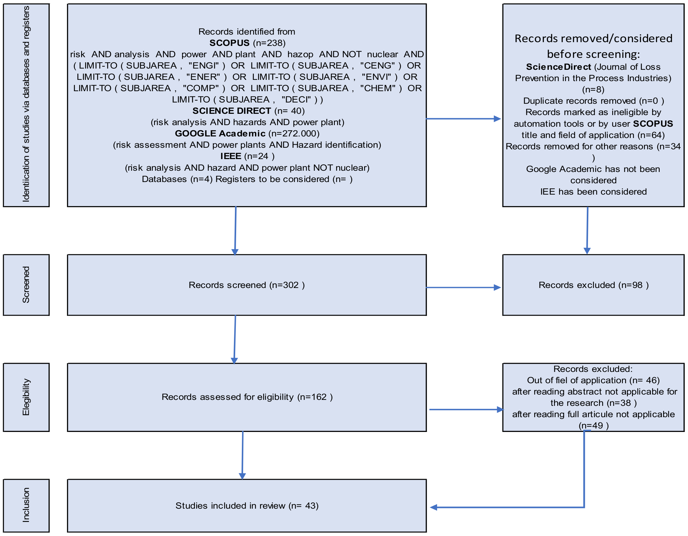
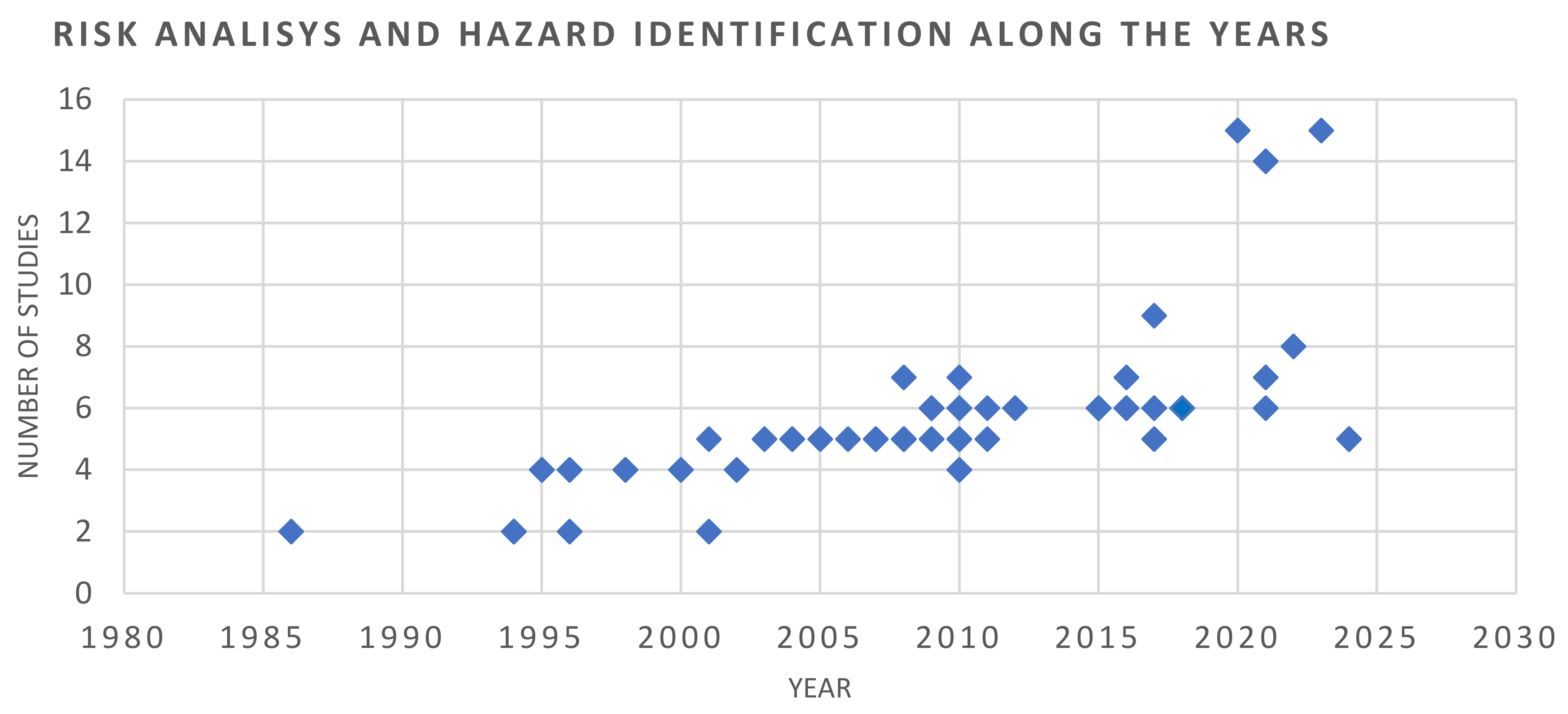
2. Literature Review
3. Materials and Methods
4. Results and Discussion
- A reactive response of the utility sector to the adoption and adequation of the systems and standards commonly used in other industries of reference in this field was detected. The sector incorporates the improvements and updates that are led by other industrial sectors in this field, slowly and not always adequately. An example is the HAZOP technique incorporated some years late.
- Incorporation of inherently safer design practices at the early stages of the project is an improvement area to be considered. Although the design of the areas of the plant considers the selection of inherently safer designs, it is not implemented as a prioritized and mandatory design, so there are no justifications or specific studies to this objective. A specific study that deals with these relevant subjects for the process safety could be incorporated.
- It would be convenient to implement Human Factor Analysis (HFA) to review the risks and problems related to human factors in relation to ergonomic, potential human errors, and problems such as alarm prioritization, tagging, signaling, noise, and lighting. The incorporation, as a standard practice, of the preparation of specific studies, SIS/SIL and ESD, is highly recommended. This would simplify and clarify the application and compliance with the IEC standards.
- Critical issue. It has been confirmed that construction companies do not perform process risk analysis and HAZOP for the temporary systems usually installed during commissioning and start-up. This can result in accidents during commissioning.
4.1. Temporary Systems for Commissioning
- Process and mechanical systems:
- Chemical cleaning.;
- Cleaning with air, water, or other products.
- Steam blowing of piping.
- Piping and temporary installations of liquid or gaseous fuels.
- Inertization of piping and equipment.
- Electrical systems:
- Temporary power supply with diesel generators.
- Temporary interconnections.
- Provisional power supply and distribution.
- Uninterrupted and backup temporary power supply.
- Electrical systems in operation without the final protection settings, and therefore with temporary settings that can produce hazards and risks that are not present under normal operating conditions.
- Instrumentation and control systems:
- Protection systems with preliminary settings, since the plant is not operating under normal conditions.
- Temporary control logics necessary for performance of certain tests.
- Non-operative alarms or alarms with preliminary settings, because the construction is not completely finalized.
- Disconnected signals or incomplete control loops, which require modifications in the control logics until the erection is finalized.
4.2. Selection of the Methodology
- Initial stage for evaluation of the documentation and state of the installation;
- Hazard identification and risk analysis on the process and activities considered on the temporary facilities to be evaluated.
- Scenario-based;
- Non-scenario-based.
- Preliminary Hazard Analysis (PHA);
- Safety Review (SR);
- Relative Ranking (RR);
- Checklist.
- What-If Analysis.
- What-If Analysis/Checklist.
- Hazard and Operability Studies (HAZOP);
- Failure Modes and Effects Analysis (FMEA);
- Fault Tree Analysis (FTA);
- Event Tree Analysis (ETA);
- Cause–Consequence Analysis (CCA) and bow tie analysis.
- Checklists.
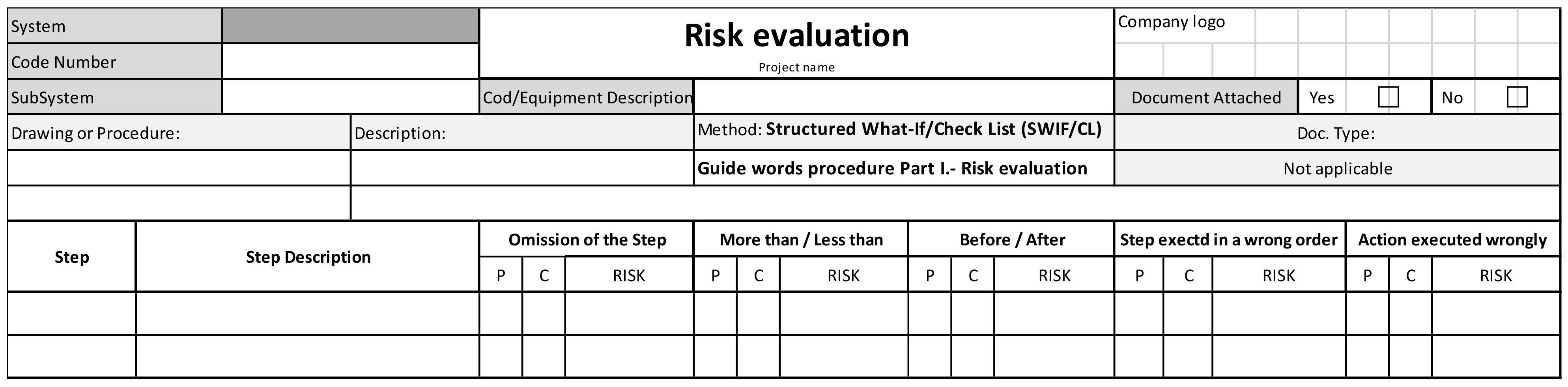
- Application of SWIFT (Structured What-If Technique) with preselected guide words.
- Application of techniques of HAZOP applied to procedures, using questions related to incorrect operations or non-executed operations.
4.3. Description of the Methodology
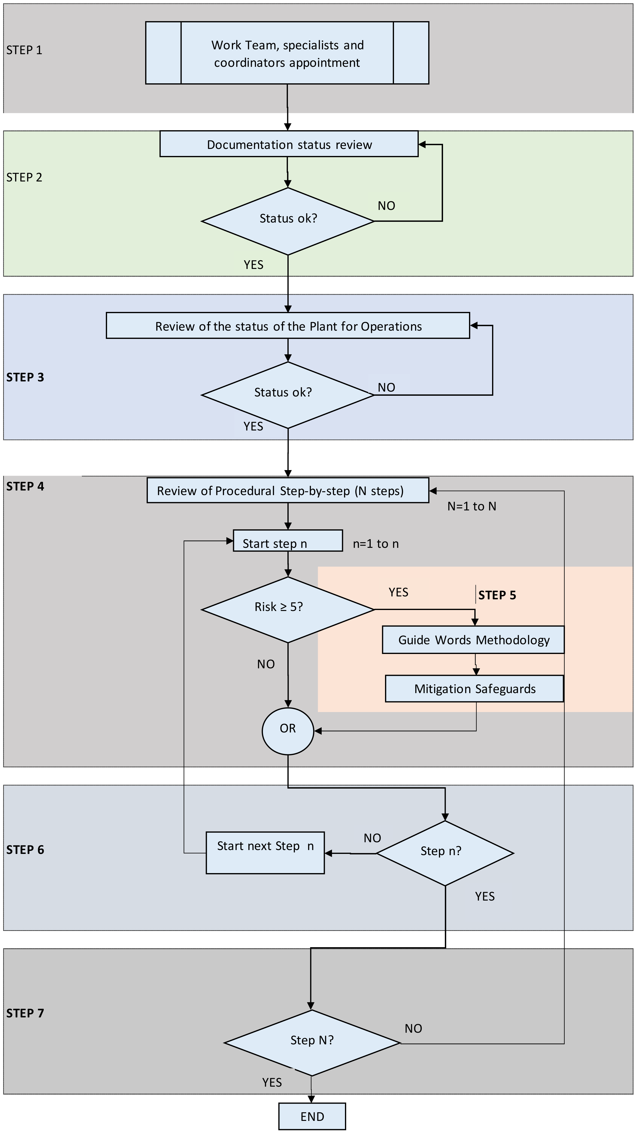
4.4. Procedure
- Preparing for the review, including the scope of the review and the necessary documentation.
- Performing the review, establishing the basic rules for the review, and the preselected guide words.
- Documenting the results of the review adequately.
4.4.1. Preparing for the Review and Necessary Documentation
- Detailed scope of the system, including lists with battery limits and system tie-ins.
- Description of the process, base of the temporary system to be implemented.
- Flow diagrams and P & IDs of the system.
- Lists and data sheets of the chemical products that will be used in the process of the temporary system. Safety data sheets of the products (SDS). Preferably, the SDS of the products will be provided in the official format of the country where the project takes place, or in the format of international organizations, always in accordance with the normal practices of the product supplier.
- Lists and data sheets of the equipment comprising the systems.
- Layout drawings of the equipment and general arrangement where the location and layout of the equipment and components of the temporary system are shown.
- Isometric drawings and/or piping plan drawings of the system. It is important that this documentation show the scope of the temporary system and the interconnection with the permanent installation.
- List of the material parts of the temporary system: data sheets of piping and/or components in case these include any not forecasted for the project. It is recommended to list the requirements of the equipment comprising part of the permanent installation when required. This facilitates the identification of mistakes in the design conditions of the equipment, components, and others and facilitates the review.
- Procedure for the execution of the system. The following points, as a minimum, shall be included:
- Procedure for filling the system. Considering the initial conditions of the system.
- Procedure for the start-up and initial start-up.
- Procedure for normal and emergency operation.
- Procedure for shutdown.
- Other procedures as necessary.
- 10.
- Risk evaluation of the system. In this point, the usual activities related to the installation and handling of chemical products, as well as the main hazards and risks associated with the operation, are included. Normally, this is approached from a perspective related to the occupational health of the workers, and not so much from the point of view of identification of hazards and risk evaluation of the process.
- 11.
- Procedures for sampling in case they are required by the system (for example, to determine certain parameters of water or steam in systems that provide a certain degree of cleanliness).
- 12.
- Inspection and test plan. It is possible that this plan, besides incorporating the inspections of the activities of the system, incorporates inspections during the manufacturing of pieces or components necessary for the system.
- 13.
- Other documentation that is considered relevant to perform the risk assessment with the required guarantees by the specialists. For example, ambient conditions for some tests, notices to the nearby population or to the authorities, etc.
4.4.2. Performing the Review. Rules and Guide Words Recommended
- That the status of the system and the documentation are acceptable to proceed with the risk evaluation; or
- That the status of the system and/or the documentation are not acceptable to allow proceeding with the risk evaluation.
- Health and safety at work issues. Special attention shall be given to the requirements of HSE and to ensure the provision of personal protection means, that communication devices are available and operative, that accessibility to the working area is adequate, that the permits to work have been issued, that Job Safety Analysis (JSA) has been performed, and that the required control and mitigation measures of the risks have been implemented.
- Emergency systems, such as fire protection and public address systems are checked.
- Issues related to the operation of the system are reviewed. Automatic and manual operations, training of the operators, and necessary temporalities required for the operation of the system are also checked. Steps of the sequences are correctly identified and the criteria for achievement of the steps are also identified.
- Initial fill of the system.
- Start-up of the system.
- Shutdown of the system.
- Normal operation.
- Emptying of the system.
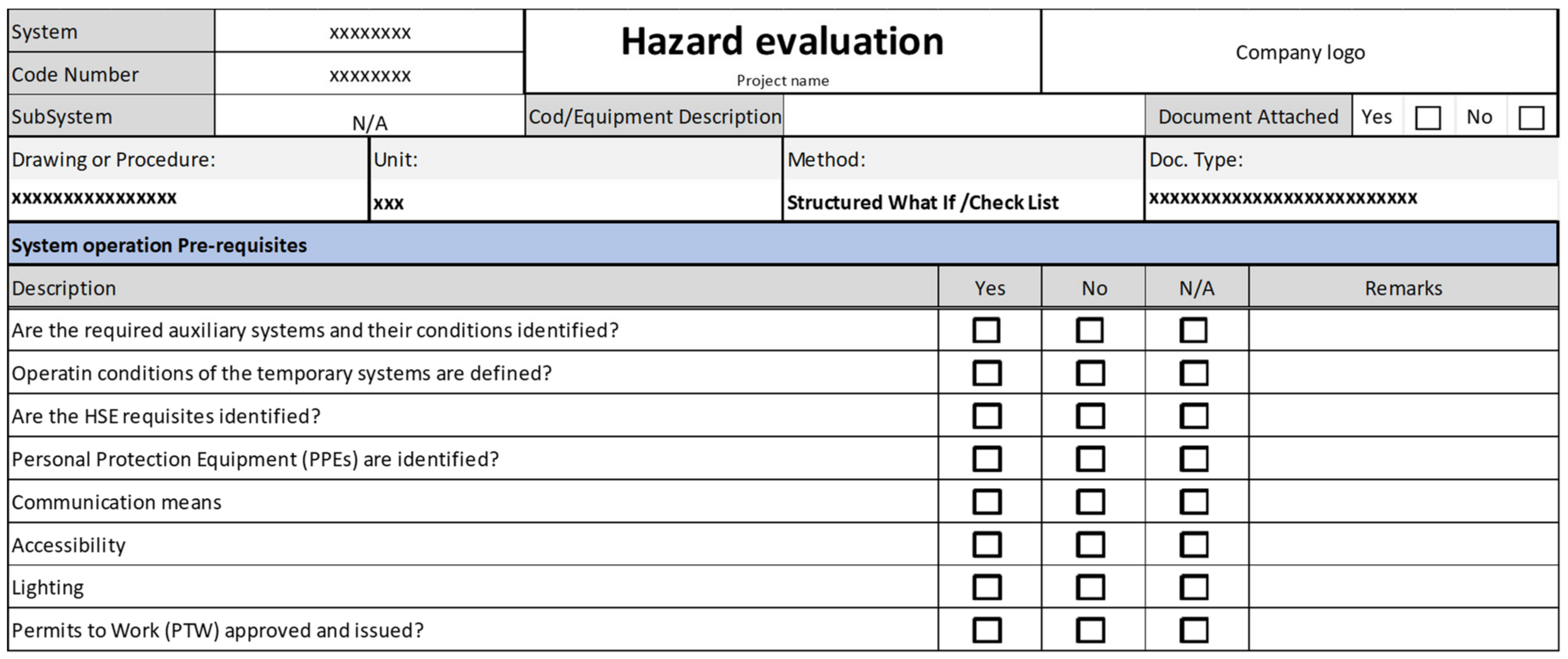
4.4.3. Documenting the Results
4.5. Application of the Methodology to a Real Project: Case Study
- Chemical cleaning of boiler and steam and water mechanical systems such as boiler feedwater, condensate, and steam systems.
- Cleaning with air, water, or other products.
- Steam blowing.
- Piping and temporary installations of liquid or gaseous fuels.
- Lube oil flushing.
- –
- Installation of adequate protection devices and equipment that guarantee safety of operations.
- –
- Verification and installation of additional local interlocks, such as thermal and pressure relief valves that increase the safety level of the temporary installation.
- –
- Incorporation of additional alarms and logics in the control systems involved, reducing the risk levels of certain operations.
- –
- Issues related to operational status of the control systems during temporary operations.
- –
- Alternative solutions of system configuration are proposed to avoid dangerous situations, accidents, or failure of equipment and components that could be working out of design conditions.
- –
- Recommendations are made to guarantee the level of education and training of the operators who will be in charge of the operations.
- –
- Preparation of specific checklists is proposed.
- –
- Double verification in the field can help to increase the safety level of operations.
- –
- Other recommendations related to spare parts or industrial safety is proposed.
- Filling test and leak test.
- Initial cleaning in closed circuit.
- Chemical cleaning.
- Drainage of the system.
- Final rinsing.
5. Conclusions
- It is an agile method that allows identifying hazardous conditions and risks during specific processes in temporary systems.
- The method uses and combines techniques with proven results, such as brainstorming.
- The short execution time required allows quick and efficient implementation.
- The method is not considered itself by international standards, unlike others such as HAZOP.
- It is necessary to know the real state of the temporary installation before carrying out the risk analysis, which depends on information provided by others.
- The necessary materials must be on site for the execution of the tasks.
- Application to temporary installations in solar thermal renewable energy plants such as thermal salt storage systems, e.g., salt melting processes or salt tank filling processes, as well as specific operations for the safety of these facilities.
- Application with the necessary adaptations to plants that use hydrogen as fuel, either in installations similar to those described here, or those that are currently under development.
- Extend the application of the proposed methodology to other disciplines, such as temporary electrical systems, with the necessary adaptations as well as the selection of the most appropriate guide words and the checklists that are required based on the new proposed systems.
Author Contributions
Funding
Institutional Review Board Statement
Informed Consent Statement
Data Availability Statement
Conflicts of Interest
Appendix A. Study Case: Application of the Methodology to a Real Power Plant
- Filling test and leak test.
- Initial cleaning in closed circuit.
- Chemical cleaning.
- Drainage of the system.
- Final rinsing.

| System | Chemical Cleaning | Risk Evaluation Project Name | Company Logo | ||||||||||||||||
|---|---|---|---|---|---|---|---|---|---|---|---|---|---|---|---|---|---|---|---|
| Code Number | Chapter 7.1 | ||||||||||||||||||
| SubSystem | N/A | Cod/Equipment Description | Document Attached | Yes |  | No | | ||||||||||||
| Drawing or Procedure: | Description: | Method: Structured What-If/Check List (SWIF/CL) | Doc. Type: | ||||||||||||||||
| 7.1.2.1.-Chemical Cleaning | Light F.O. Chemical Cleaning Procedure | Guide Words Procedure Part I.-Risk Evaluation | Not Applicable | ||||||||||||||||
| Activity: 7.1.2.1.1.-Initial Filling & Leak Test | Description: Temporary Connections Flanged or Threaded and Elements to Be Removed or Replaced | ||||||||||||||||||
| Step | Step Description | Omission of the Step | More Than/Less Than | Before/After | Step Exectd in a Wrong Order | Action Executed Wrongly | |||||||||||||
| P | C | RISK | P | C | RISK | P | C | RISK | P | C | RISK | P | C | RISK | |||||
| 1.1 | Fuel tank connections preparation | ||||||||||||||||||
| 1.1.1 | Remove check valve internals | 3 | 3 | 9 | 1 | 1 | 1 | 1 | 1 | 1 | 3 | 1 | 3 | 3 | 3 | 9 | |||
| 1.1.2 | Remove valve internals | 3 | 3 | 9 | 1 | 1 | 1 | 1 | 1 | 1 | 3 | 1 | 3 | 3 | 3 | 9 | |||
| 1.1.3 | Prepare DN50 PN16flange connection | 3 | 1 | 3 | 1 | 1 | 1 | 1 | 1 | 1 | 3 | 1 | 3 | 3 | 3 | 9 | |||
| 1.1.4 | Prepare DN100 PN16 flange connection | 3 | 1 | 3 | 1 | 1 | 1 | 1 | 1 | 1 | 3 | 1 | 3 | 3 | 3 | 9 | |||
| 1.1.5 | Remove valve internals | 3 | 3 | 9 | 1 | 1 | 1 | 1 | 1 | 1 | 3 | 1 | 3 | 3 | 3 | 9 | |||
| 1.1.6 | Blind PSV | 3 | 3 | 9 | 1 | 1 | 1 | 1 | 1 | 1 | 3 | 1 | 3 | 3 | 3 | 9 | |||
| 1.1.7 | Prepare DN50 PN16flange connection | 3 | 1 | 3 | 1 | 1 | 1 | 1 | 1 | 1 | 3 | 1 | 3 | 3 | 3 | 9 | |||
| Value | Description | Reference Values for Estimation |
|---|---|---|
| 1 | Highly unlikely | Extremely remote chance of occurrence (<10 −5 year) |
| 2 | Unlikely | Rare event. An event not likely during operations (1 × 10⁻⁴ year) |
| 3 | Likely | An infrequent event. An event that may occur during operations (1 × 10⁻³ year) |
| 4 | Probable | An event likely to occur in working lifetime of plant operations (10−1 to 10−1 per year). |
| 5 | Frequent | Happens several times per year. A common event that is likely to occur several times per year. |
| Value | Description | People | Environment | Assets |
|---|---|---|---|---|
| 1 | Negligible | Slight: First aid injury | Loss of containment: No escape to the environment. | Minor equipment damage: No delay in operations. |
| 2 | Minor | Minor injury: No irreversible effect | Loss of containment: Minor escape to the environment. | Minor equipment damage: Up to 1 day delay in operations. |
| 3 | Significant | Major injury: Permanent disability and health effects | Loss of containment: Significant escape to the environment. | Minor equipment damage: Several days of delay in operations. |
| 4 | Severe | Fatality/ies (1–2): Multiple major injuries/permanent disability | Major damage: Loss of containment with significant escape to the environment. | Major impact: Severe damage to assets. Extended loss of operations. Partial loss of plant unit. |
| 5 | Catastrophic | Multiple fatalities on-site and/or several major injuries off-site | Extensive damage: Major loss of containment. | Massive impact: Total loss of major plant unit and possible damage to adjacent units. |

| System | Chemical Cleaning | Hazard Evaluation Project Name | Company Logo | |||||
|---|---|---|---|---|---|---|---|---|
| Code Number | Chapter 7.1 | |||||||
| SubSystem | N/A | Cod/Equipment Description | Document Attached | Yes | | No | | |
| Drawing or Procedure: | Unit: | Method: Structured What-If/Check List | Doc. Type: | |||||
| 7.1.2.1.- Chemical Cleaning | Light F.O. Chemical Cleaning Procedure | Guide Words Procedure Part II | Not Applicable | |||||
| Node: 7.1.2.1.1.- Initial Filling & Leak Test | Description: Temporary Connections Flanged or Threaded and Elements to Be Removed or Replaced | |||||||
| Item | Deviation | Causes | Consequences | Safeguards | Recommendation | |||
| 1.1.1 | Remove check valve internals Case: Omission of Step Case: Action executed wrongly | Operator mistake | 1.- Damage to valve trim | 1.- Test and Inspection Plan Check List Paragh 4.2. Walkdown to check step completion | 1.- Be sure spare parts availability 2.- To Include a Task List with a specific checklist for checking that the step has been properly carried out. 3.- to define an independent field team for review correct execution of the step. On field double checking. 4.- To Incorporate a signature of the team (operator and supervisor) responsible. | |||
| 2.- Neccesary spare parts trim valve | ||||||||
| 3.- Commissioning schedule delay | ||||||||
| 1.1.2 | Remove Control valve internals Case: Omission of Step Case: Action executed wrongly | Operator mistake | 1.- Damage to valve trim | 1.- Test and Inspection Plan Check List Paragh 4.2. Walkdown to check step completion | 1.- Be sure spare parts availability 2.- To Include a Task List with a specific checklist for checking that the step has been properly carried out. 3.- to define an independent field team for review correct execution of the step. On field double checking. 4.- To Incorporate a signature of the team (operator and supervisor) responsible. | |||
| 2.- Neccesary spare parts trim valve | ||||||||
| 3.- Commissioning schedule delay | ||||||||
| System | Chemical Cleaning | Risk Evaluation Project Name | Company Logo | |||||||||||||
|---|---|---|---|---|---|---|---|---|---|---|---|---|---|---|---|---|
| Code Number | Chapter 7.1 | |||||||||||||||
| SubSystem | N/A | Cod/Equipment Description | Document Attached | Yes | | No | | |||||||||
| Drawing or Procedure: | Description: | Method: Structured What-If/Check List (SWIF/CL) | Doc. Type: | |||||||||||||
| 7.1.2.1.- Chemical Cleaning | Light FO Chemical Cleaning Procedure | Guide Words Procedure Part I.- Risk Evaluation | Not Applicable | |||||||||||||
| Activity: 7.1.2.1.3.- Chemical cleaning | Description: Fuel Oil Chemical cleaning | |||||||||||||||
| Step | Step Description | Omission of the Step | More Than/Less Than | Before/After | Step Exectd in a Wrong Order | Action Executed Wrongly | ||||||||||
| P | C | RISK | P | C | RISK | P | C | RISK | P | C | RISK | P | C | RISK | ||
| 3.1 | Heat up system to approximately 45 °C | |||||||||||||||
| 3.1.1 | Check Auxiliary boiler is ready for Operation | 1 | 1 | 1 | 1 | 1 | 1 | 1 | 1 | 1 | 1 | 1 | 1 | 1 | 1 | 1 |
| 3.1.2 | Verify all connections are correctly installed. | 1 | 1 | 1 | 1 | 1 | 1 | 1 | 1 | 1 | 1 | 1 | 1 | 1 | 1 | 1 |
| 3.1.3 | Start up Auxiliary Boiler. | 1 | 1 | 1 | 3 | 4 | 12 | 1 | 1 | 1 | 1 | 1 | 1 | 3 | 3 | 9 |
| 3.1.4 | Increase load as needed | 3 | 2 | 6 | 3 | 4 | 12 | 1 | 1 | 1 | 1 | 1 | 1 | 3 | 3 | 9 |
| 3.1.5 | Open manual valve for heating header of chemical cleaning solution | 1 | 1 | 1 | 3 | 4 | 12 | 1 | 1 | 1 | 1 | 1 | 1 | 3 | 3 | 9 |
| 3.1.6 | Control Temperature up to 45 °C of water throug local temperatura indicator | 1 | 1 | 1 | 3 | 3 | 9 | 3 | 3 | 9 | 1 | 1 | 1 | 1 | 1 | 1 |
| 3.2 | Degreasing stage | |||||||||||||||
| 3.2.1 | surfactant 0.05% and caustic soda 0.25% | 1 | 1 | 1 | 4 | 4 | 16 | 1 | 1 | 1 | 3 | 3 | 9 | 1 | 1 | 1 |
| 3.2.2 | dosing manually using temporary mixing tank | 1 | 1 | 1 | 3 | 3 | 9 | 1 | 1 | 1 | 1 | 1 | 1 | 3 | 3 | 9 |
| 3.3 | Heat up system to 60 ± 5 °C | |||||||||||||||
| 3.3.1 | Heating proccess as per 3.1. up to 60 ± 5 °C | 3 | 2 | 6 | 4 | 4 | 16 | 3 | 3 | 9 | 1 | 1 | 1 | 3 | 3 | 9 |
| 3.3.2 | Temperature, Alkalinity and pH will be monitored every hour | 3 | 3 | 9 | 3 | 3 | 9 | 3 | 3 | 9 | 1 | 1 | 1 | 3 | 3 | 9 |
| 3.4 | Acid stage | |||||||||||||||
| 3.4.1 | When T = 60 °C close steam injection valve | 4 | 4 | 16 | 3 | 3 | 9 | 4 | 4 | 16 | 4 | 4 | 16 | 3 | 3 | 9 |
| 3.4.2 | Dosing citric acid 3%, ammonium bifluoride 0,3% and corrosion inhibitor0,2% | 1 | 1 | 1 | 4 | 4 | 16 | 1 | 1 | 1 | 4 | 4 | 16 | 3 | 3 | 9 |
| 3.4.3 | Temperature, acidity, pH, Fe3 +, Fetot y Inhibitor efficiency will be monitored every hour | 3 | 3 | 9 | 3 | 3 | 9 | 3 | 3 | 9 | 1 | 1 | 1 | 3 | 3 | 9 |
| 3.4.4 | Check ph is between 3–4 | 1 | 1 | 1 | 3 | 3 | 9 | 1 | 1 | 1 | 1 | 1 | 1 | 3 | 3 | 9 |
| 3.4.5 | Verify Fetot remain stable==> end acid stage | 1 | 1 | 1 | 3 | 3 | 9 | 1 | 1 | 1 | 1 | 1 | 1 | 3 | 3 | 9 |
| 3.5 | Pasivation stage | |||||||||||||||
| 3.5.1 | Increase ph up to 7–7.5 dosing NaOH | 1 | 1 | 1 | 4 | 4 | 16 | 1 | 1 | 1 | 3 | 3 | 9 | 1 | 1 | 1 |
| 3.5.2 | NaOH must be dosing slowly | 1 | 1 | 1 | 3 | 3 | 9 | 1 | 1 | 1 | 1 | 1 | 1 | 3 | 3 | 9 |
| 3.5.3 | Inyectar Nitrito de sodio 0.3% con Ph = 7–7.5 | 1 | 1 | 1 | 4 | 4 | 16 | 1 | 1 | 1 | 3 | 3 | 9 | 1 | 1 | 1 |
| 3.5.4 | Check temperature is 30–40 °C | 1 | 1 | 1 | 1 | 1 | 1 | 1 | 1 | 1 | 1 | 1 | 1 | 1 | 1 | 1 |
| 3.5.5 | Monitor each hour:Temp, pH, Fe3+ y Fetot | 3 | 3 | 9 | 3 | 3 | 9 | 3 | 3 | 9 | 1 | 1 | 1 | 3 | 3 | 9 |
| 3.5.6 | Check stability Fe3+ | 1 | 1 | 1 | 3 | 3 | 9 | 1 | 1 | 1 | 1 | 1 | 1 | 3 | 3 | 9 |
| System | Chemical Cleaning One Phase | Hazard Evaluation | Company Logo | |||||
|---|---|---|---|---|---|---|---|---|
| Code Number | Chapter 7.1 | Project Name | ||||||
| SubSystem | N/A | Cod/Equipment | Document Attached | Yes | No | |||
| Description | ||||||||
| Drawing or Procedure: | Unit: | Method: Structured What-If/Check List | Doc. Type: | |||||
| 7.1.2.1.- Chemical Cleaning | Light F.O. Chemical Cleaning Procedure | Guide Words Procedure Part II | Not Applicable | |||||
| Node: 7.1.2.1.3.- Chemical Cleaning | Description: Light F.O. Chemical Cleaning | |||||||
| Item | Deviation | Causes | Consequences | Safeguards | Recommendation | |||
| 3.1.3 | Auxiliary Boiler start up from Local Control Panel | Steam pressure of Auxiliary Boiler higher than set point | 1.-Overpressure in the boiler, risk of explosion. | 1.- Pressure relief valve at the boiler outlet. | 1.- To Provide detailed operating instructions for the local operation of the boiler. | |||
| Case: More/Less than | 2.- High pressure trip in the boiler. Steam outlet shut-off. | 2.- To Provide a list of settings for the Auxiliary Boiler operation, trips and alarms | ||||||
| Case: Action executed wrongly | 2.- Overpressure in the temporary connections to the header. Possible breaking of the temporary hoses with leakage of water at high temperature and pressure. | 3.- Shutdown of fuel and steam supply to the system. | ||||||
| 3.- Potential damage to the people and the environment | ||||||||
| Caso: More/Less than | See more pressure | See more pressure | ||||||
| 3.1.4 | Increase boiler load if required | See more pressure (case 3.1.3.) | ||||||
| Case: More/Less than. | ||||||||
| Action executed wrongly | ||||||||
| 3.1.5 | Open manual valve for heating header of chemical cleaning solution | Operator open the valve more than necessary | 1.- High temperature on return main header | 1.-Local thermometer for temperature measurement. | 1.-To install an local alarm device (temperature switch) when the temperature rises above the set point. | |||
| Case: More/Less temperature than expected. | 2.- Operating instructions | 2.- To install a isolation device for T > 70 °C and T = 45 °C for the heating stage. | ||||||
| Case: Action executed wrongly | 2.-Possible breaking of the temporary hoses with leakage of water at high temperature and pressure. | 3.- Evaluate the installation of a protection circuit in the local panel to acting on the isolation device for item 2 when overpressure and/or over-temperature happens. | ||||||
| 3.- Potential damage to the people and the environment | ||||||||
| System | Chemical Cleaning One Phase | Hazard Evaluation | Company Logo | |||||
|---|---|---|---|---|---|---|---|---|
| Code Number | Chapter 7.1 | Project Name | ||||||
| SubSystem | N/A | Cod/Equipment Description | Document Attached | Yes | No | |||
| Drawing or Procedure: | Unit: | Method: Structured What-If/Check List | Doc. Type: | |||||
| 7.1.2.1.- Chemical Cleaning | Light F.O. Chemical Cleaning Procedure | Guide Words Procedure Part II | Not Applicable | |||||
| Node: 7.1.2.1.3.- Chemical Cleaning | Description: Light F.O. Chemical Cleaning | |||||||
| Item | Deviation | Causes | Consequences | Safeguards | Recommendation | |||
| 3.2.1 | Dosing surfactant 0.05% and caustic soda 0.25% slowly to temporary mixing tank | Operator dosing more product than required to the temporary mixing tank. | 1.- High concentration of degreasing product on the temporary mixing tank | 1.-Use of Personal Protective Equipment. | 1.- Be sure to regulate the liquid chemical feed flow with the manual pump. | |||
| & | Case: More/Less than | 1.- More surfactant | 2.- For dosing of surfactant (liquid) a pneumatic pump is used. | 2.- To provide the quantities to be dosed for caustic soda in order to avoid major mistakes by the operator. Simple data to be provided. | ||||
| 3.2.2 | Case: Action executed wrongly | 2.- More caustic soda (sodium hydroxide) because operation is manual by emptying bags | 3.-Operating Instructions and Safety Data Sheets for chemical products (SDS) | 3.- Ensure the emptying from the mixing tank to the effluent basin to recover the degreasing solution. | ||||
| 4.- Be sure portable eyewash shower is installed. | ||||||||
| 2.- pH increasing in the mixed solution. | ||||||||
| 3.- Potential damage to the people and the environment depending of the concentration of the products | ||||||||
| 3.3.1 | Heating up in accordance with paragraph 3.1 up to 60 ± 5 °C | Operator open the manual valve more than necessary. | 1.- High temperature on return main header | 1.-Local thermometer for temperature measurement. | 1.-To install an local alarm device (temperature switch) when the temperature rises above the set point. | |||
| Case: More/Less temperature than expected. | 2.-Design conditions for piping and mechanical equipments. | 2.- To install a isolation device for T > 70 °C and T = 45 °C for the heating stage. | ||||||
| Case: Action executed wrongly | 2.-Possible breaking of the temporary hoses with leakage of water at high temperature and pressure. | 3.- Operating instructions | 3.- Evaluate the installation of a protection circuit in the local panel to acting on the isolation device for item 2 when overpressure and/or over-temperature happens. | |||||
| 3.- Potential damage to the people and the environment | ||||||||
- Install pressure safety valves in the circuit to avoid pressures that lead to the failure of the temporary hoses.
- Check the settings and the calibration certificates of the PSVs.
- Install devices for alarm and shutdown in case of too high temperatures. Modify the local panel.
- Install an interlock device in the feeding system of chemical products to the water when steam is being injected.
- Provide the exact quantities of chemical products to be dosed and devices that guarantee their feed.
- Implement checklists that assure the correct performance of the operations. The double-checking of some operations penalizes the execution time and the cost of the number of operators but assures the correct performance of the works.
- Install eye washers in the proximity of the temporary system.
References
- International Energy Agency. Key World Energy Statistics 2020; International Energy Agency: Paris, France, 2020; Volume 33. [Google Scholar]
- Capros, P.; De Vita, A.; Tasios, N.; Siskos, P.; Kannavou, M. EU Reference Scenario 2016—Energy, Transport and GHG Emissions—Trends to 2050; Publications Office of the European Union: Luxembourg, 2016. [Google Scholar] [CrossRef]
- IEC/ISO 31000; UNE-ISO 31000 Gestión Del Riesgo. Directrices. AENOR: Madrid, Spain, 2018.
- IEC/ISO 31010; UNE-EN 31010 Gestión Del Riesgo Técnicas de Apreciación Del Riesgo. AENOR: Madrid, Spain, 2011.
- España Ministerio de la Presidencia. Real Decreto 840/2015, de 21 de Septiembre, Por El Que Se Aprueban Medidas de Control de Los Riesgos Inherentes a Los Accidentes Graves en LOS Que Intervengan Sustancias Peligrosas; España Ministerio de la Presidencia: Madrid, Spain, 2015; pp. 97531–97567. [Google Scholar]
- Unión Europea. Directiva 2012/18/UE Relativa Al Control de Los Riesgos Inherentes a Los Accidentes Graves En Los Que Intervengan Sustancias Peligrosas; Unión Europea: Brussels, Belgium, 2012; pp. 1–37. [Google Scholar]
- Hawksley, J.L. Risk Management Practice in the Process Industries. 2012, Volume 1. Available online: https://epsc.be/Documents/Reports/EPSC+Reports+Available/_/report18.pdf (accessed on 1 March 2020).
- U.S. Department of Labor Occupational Safety and Health. OSHA 3132 2000 Process Safety Management (PSM). Occupational Safety and Health Act; 2000. Available online: https://www.osha.gov/sites/default/files/publications/osha3132.pdf (accessed on 1 March 2020).
- Arendt, S.; Lorenzo, D.; Bradshaw, B.; Vanden Huevel, L.; Frank, W. Guidelines for Risk Based Process Safety; John Wiley & Sons, Inc.: Hoboken, NJ, USA, 2007. [Google Scholar]
- American Petroleum Institute. API Recommended Practice 1173 Pipeline Safety Management System Requirements; American Petroleum Institute: Washington, DC, USA, 2015. [Google Scholar]
- American Chemistry Council (ACC). Responsible Care Management System® and Certification; American Chemistry Council (ACC): Washington, DC, USA, 2013. [Google Scholar]
- Wu, Y.C.; Laiwang, B.; Shu, C.M. Investigation of an Explosion at a Styrene Plant with Alkylation Reactor Feed Furnace. Appl. Sci. 2019, 9, 503. [Google Scholar] [CrossRef]
- Page, M.J.; McKenzie, J.E.; Bossuyt, P.M.; Boutron, I.; Hoffmann, T.C.; Mulrow, C.D.; Shamseer, L.; Tetzlaff, J.M.; Akl, E.A.; Brennan, S.E.; et al. The PRISMA 2020 Statement: An Updated Guideline for Reporting Systematic Reviews. BMJ 2021, 372, n71. [Google Scholar] [CrossRef] [PubMed]
- Torres-Echeverria, A.C. On the Use of LOPA and Risk Graphs for SIL Determination. J. Loss Prev. Process Ind. 2016, 41, 333–343. [Google Scholar] [CrossRef]
- Safira Rahmania, W.; Elvian Gayuh Prasetya, H.; Hesty Sholihah, F. Maintenance Analysis of Boiler Feed Pump Turbine Using Failure Mode Effect Analysis (Fmea) Methods. In Proceedings of the IES 2020—International Electronics Symposium: The Role of Autonomous and Intelligent Systems for Human Life and Comfort, Surabaya, Indonesia, 29–30 September 2020; pp. 54–59. [Google Scholar] [CrossRef]
- Buchta, J.; Oziemski, A.; Oziemski, M. Analysis of Technical Condition of Lignite-Fired Power Units as the Way of Reducing the Operational Risks. In Proceedings of the 2019 20th International Scientific Conference on Electric Power Engineering, EPE 2019, Kouty nad Desnou, Czech Republic, 15–17 May 2019. [Google Scholar] [CrossRef]
- Putra, G.P.; Purba, H.H. Failure Mode and Effect Analysis on Power Plant Boiler. J. Optim. Ind. Eng. 2018, 11, 1–5. [Google Scholar] [CrossRef]
- Ferreira, I.H.F. Industrial Risk Management of a Combined Cycle Power Plant; Instituto Superior Técnico, Universidade Técnica de Lisboa: Lisboa, Portugal; pp. 1–10. Available online: https://fenix.tecnico.ulisboa.pt/downloadFile/395137855081/Artigo.pdf (accessed on 20 February 2020).
- Gu, Y.; Gao, Z.; Wang, X.; Yang, K.; Chen, K. Research on the Construction of Fault Knowledge Base for Power Plant Equipments. In Proceedings of the World Automation Congress Proceedings, Puerto Vallarta, Mexico, 24–28 June 2012. [Google Scholar]
- Murariu, A.C.; Mateiu, H.; Grabulov, V.; Paşca, N. Risk Assessment of Thermal Power Plant. Rev. Energetica 2009, 57, 627–630. [Google Scholar]
- De Siqueira, I.P.; De Souza, B.A. Risk Assessment of Major Accidents in Large Electric Power Plants. In Proceedings of the 2010 IEEE PES Transmission and Distribution Conference and Exposition: Smart Solutions for a Changing World, New Orleans, LA, USA, 19–22 April 2010. [Google Scholar] [CrossRef]
- Zafra-Cabeza, A.; Ridao, M.A.; Alvarado, I.; Camacho, E.F. Applying Risk Management to Combined Heat and Power Plants. IEEE Trans. Power Syst. 2008, 23, 938–945. [Google Scholar] [CrossRef]
- Kumar, R. Coal-Fired Power Plant Risk Evaluation Strategy. In Proceedings of the IEEE-International Conference on Advances in Engineering, Science and Management, ICAESM-2012, Nagapattinam, India, 30–31 March 2012; pp. 84–89. [Google Scholar]
- Al Saffar, I.Q.; Ezzat, A.W. Qualitative Risk Assessment of Combined Cycle Power Plant Using Hazards Identification Technique. J. Mech. Eng. Res. Dev. 2020, 43, 284–293. [Google Scholar]
- Qi-quan, W. Risk Analysis and Control Measure of Gas Power Generation Enterprise. Int. J. Sci. Qual. Anal. 2017, 3, 15. [Google Scholar] [CrossRef]
- Alrifaey, M.; Hong, T.S.; Supeni, E.E.; As’arry, A.; Ang, C.K. Identification and Prioritization of Risk Factors in an Electrical Generator Based on the Hybrid FMEA Framework. Energies 2019, 12, 649. [Google Scholar] [CrossRef]
- Musyafa, A.; Adiyagsa, H. Hazard and Operability Study in Boiler System of The Steam Power Plant. Int. J. Sci. Technol. IJSTE 2012, 1, 1–10. [Google Scholar]
- Rathod, R.; Gidwani, G.D.; Solanky, P. Hazard Analysis and Risk Assesment in Thermal Power Plant. Int. J. Eng. Sci. Res. Technol. 2017, 177, 177–185. [Google Scholar] [CrossRef]
- Gu, D.X.; Liang, C.Y.; Bichindaritz, I.; Zuo, C.R.; Wang, J. A Case-Based Knowledge System for Safety Evaluation Decision Making of Thermal Power Plants. Knowl.-Based Syst. 2012, 26, 185–195. [Google Scholar] [CrossRef]
- Yang, Z.X.; Song, L.; Zhang, C.Y.; Li, C.; Yuan, X.B. Mathematical Safety Assessment Approaches for Thermal Power Plants. Math. Probl. Eng. 2014, 2014, 864682. [Google Scholar] [CrossRef]
- Wang, Y.; Yuan, J.; Zhang, D. Failure Mode Risk Analyzing Based on Grey Theory for Power Plant Steam Turbine Proper. In Proceedings of the 2009 IEEE 16th International Conference on Industrial Engineering and Engineering Management, Beijing, China, 21–23 October 2009; pp. 1234–1238. [Google Scholar] [CrossRef]
- Duan, L.; Niu, D.; Lv, H.; Kou, B. Risk Assessment of Thermal Power Plant Project Based on Fuzzy Analytic Hierarchy Process in the Early Operation. In Proceedings of the 2nd International Workshop on Computer Science and Engineering, WCSE 2009, Qingdao, China, 28–30 October 2009; Volume 1, pp. 473–477. [Google Scholar] [CrossRef]
- Boyen, X.; Wehenkel, L. Automatic Induction of Fuzzy Decision Trees and Its Application to Power System Security Assessment. Fuzzy Sets Syst. 1999, 102, 3–19. [Google Scholar] [CrossRef]
- Agarwal, M. Risk Proiorization in a Gas Power Plant Using Fuzzy Inference System. IEEE 2018, 6, 753–757. [Google Scholar]
- Ebrahimnejad, S.; Mousavi, S.M.; Mojtahedi, S.M.H. A Fuzzy BOT Project Risk Evaluation Model in Iranian Power Plant Industry. In Proceedings of the 2008 IEEE International Conference on Industrial Engineering and Engineering Management, IEEM 2008, Singapore, 8–11 December 2008; pp. 1038–1042. [Google Scholar] [CrossRef]
- Gu, Y.J.; Chen, K.L.; Yang, K. Fuzzy Comprehensive Evaluation Method Based on Analytic Hierarchy Process for Falt Risk Analysis of Power Plant Equipment. In Proceedings of the 5th International Conference on Fuzzy Systems and Knowledge Discovery, FSKD 2008, Jinan, China, 18–20 October 2008; Volume 3, pp. 443–448. [Google Scholar] [CrossRef]
- Niu, D.; Wang, Y.; Xiaoyong, M. Power Plant Construction Project Safety Management Evaluation with Fuzzy Neural Network Model. In Proceedings of the 2008 IEEE Asia-Pacific Conference on Circuits and Systems, Proceedings, APCCAS 2008, Macao, China, 30 November–3 December 2008; Volume 21, pp. 489–492. [Google Scholar] [CrossRef]
- Cinar, D.; Kayakutlu, G. Scenario Analysis Using Bayesian Networks: A Case Study in Energy Sector. Knowl.-Based Syst. 2010, 23, 267–276. [Google Scholar] [CrossRef]
- Kim, H.; Singh, C. Power System Probabilistic Security Assessment Using Bayes Classifier. Electr. Power Syst. Res. 2005, 74, 157–165. [Google Scholar] [CrossRef]
- Sinha, A.K. Power System Security Assessment Using Pattern Recognition and Fuzzy Estimation. Int. J. Electr. Power Energy Syst. 1995, 17, 11–19. [Google Scholar] [CrossRef]
- Fire Loss Prevention Forum of India. Loss Prevention in Thermal Power Plants. Available online: http://www.flpfi.com/file-uploads/FLPFI_WHITEPAPER_NOV18_LR.pdf (accessed on 20 February 2020).
- Combined Cycle Journal. COMBINED CYCLE USERS GROUP: Users Reveal Their ‘Softer’ Sides. The 2016 Combined Cycle Users Group (CCUG) conference (San Antonio, August 22–25). Available online: https://www.ccj-online.com/combined-cycle-journal-number-50/combined-cycle-users-group-users-reveal-their-softer-sides/ (accessed on 20 February 2020).
- Hansen, T. Power Plant Safety. Power Engineering. 2005, pp. 20–30. Available online: https://www.power-eng.com/news/power-plant-safety/#gref (accessed on 20 February 2020).
- Durso, F. The Making of a Standard. NFPA Journal. Available online: http://www.nfpa.org/News-and-Research/Publications-and-media/NFPA-Journal/2011/November-December-2011/Features/The-Making-of-a-Standard (accessed on 20 February 2020).
- Wilson, L.; Holmstrom, D.; Tillema, D. CSB Public Meeting February 7, 2010, Natural Gas Explosion Kleen Energy Middletown, Connecticut. Available online: https://www.csb.gov/assets/1/20/kleen%20energy%20public%20meeting%20presentation_6%2028%2010.pdf?13951 (accessed on 20 February 2020).
- Proctor, D. Death Toll Rises to 43 in Wake of India Coal Plant Blast. Available online: https://www.powermag.com/death-toll-rises-to-43-in-wake-of-india-coal-plant-blast/ (accessed on 20 February 2020).
- Rathore, V. Tragic Accident: 5 People Lost Their Lives at Thermal Power Plant. Available online: https://english.newstracklive.com/news/tamil-nadu-scuddalo-refourdead-13-injured-in-boiler-explosion-at-a-thermal-power-plant-mc23-nu870-ta294-1103528-1.html (accessed on 20 February 2020).
- Center for Chemical Process Safety. Guidelines for Hazard Evaluation Procedures, 3rd ed.; John Wiley & Sons, Inc.: Hoboken, NJ, USA, 2008. [Google Scholar]
- Crawley, F. A Guide for Hazard Identification Methods; Elsevier: Amsterdam, The Netherlands, 2021. [Google Scholar] [CrossRef]
- ISO 150008; UNE ISO 150008 Análisis y Evaluación Del Riesgo Ambiental. AENOR: Madrid, Spain, 2008.
- PMBOK Guide. A Guide to the Project Management Body of Knowledge, 5th ed.; Project Management Institute, Inc.: Newtown Square, PA, USA, 2013. [Google Scholar]
- Benjamin, C.W.; Goff, S.; Hubbard, B.; Waller, R. NCB—USA National Competence Baseline v3.5; American Society for the Advancement of Project Management: Northville, MI, USA, 2008; Available online: https://www.ipma-usa.org/resources/USA_NCB.pdf (accessed on 20 February 2020).
- Kletz, T.A. Hazop & Hazan: Identifying and Assessing Process Industry Hazards, Fourth Edition; CRC Press: Boca Raton, FL, USA, 1999; p. 232. [Google Scholar]
- Sam Mannan, P.E.C. Lees’Loss Prevention in the Process Industries, 3rd ed.; Elsevier: Amsterdam, The Netherlands, 2005. [Google Scholar]
- Joaquim, C.; Helena, M.; Eulàlia, P.; Juan Antonio, V. Análisis Del Riesgo En Instalaciones Industriales; Edicions UPC: Barcelona, Spain, 1999. [Google Scholar]
- De Gracia, J.S.; Martín, T.G. Seguridad Industrial en Plantas Químicas y Energéticas. Fundamentos, Evaluación de Riesgos y Diseño, 2nd ed.; de Santos, D., Ed.; Instituto Superior de la Energía: Madrid, Spain, 2008. [Google Scholar]
- Crowl, D.A.; Lowar, J.F. Chemical Process Safety Fundamental with Applications, 2nd ed.; Pearson Education Ltd.: London, UK; Prentice Hall PTR: Hoboken, NJ, USA, 2012; Volume 16. [Google Scholar]
- Rausand, M.; Haugen, S. Risk Assessment Theory, Methods, and Applications; John Wiley & Sons, Inc.: Hoboken, NJ, USA, 2020. [Google Scholar]
- Dirección General de Protección Civil. Guia Tecnica. Métodos Cualitativos Para El Análisis de Riesgos. Protección Civ. España. 1994. Available online: https://www.proteccioncivil.es/documents/20121/85180/GUIA-TECNICA-METODOS-CUALITATIVOS-PARA-EL-ANALISIS-DE-RIESGO.pdf/d8363d70-77db-c340-a596-ae2cc5176849?t=1611325536183 (accessed on 1 February 2020).
- Dirección General de Protección Civil. Guia Técnica. Métodos Cuantitativos Para El Análisis de Riesgos. Prot. Civ. España. 1994. Available online: https://www.proteccioncivil.es/catalogo/carpeta02/carpeta22/guiatec/Metodos_cuantitativos/cuant_1.htm (accessed on 1 February 2020).
- Ruiz Gimeno, J.; Garcés de Marcilla Val, A.; Miñana Aznar, A.; González Ferradás, E.; Cano Sarabia, A.M.; Martínez Alonso, J. Casos Prácticos de Análisis de Riesgos (En Establecimientos Afectados de Nivel Inferior, En El Ámbito Del Real Decreto 1254/1999 [Seveso II]); Proteccion Civil España, Ed.; Proteccion Civil España y Universidad de Murcia: Murcia, Spain, 2005; ISBN 84-8371-499-X. [Google Scholar]
- Bestraten, M.R.; Orriols, C.M. NTP 679: Análisis Modal de Fallos y Efectos. AMFE. 2004. Available online: https://www.insst.es/documents/94886/326775/ntp_679.pdf/3f2a81e3-531c-4daa-bfc2-2abd3aaba4ba?version=1.0&t=1528460825650 (accessed on 1 February 2020).
- Standard, M. MLI-STD-1629A Procedures for Performing a Failure Mode, Effects an Critically Analysis; Washington, DC, USA, 1980. Available online: https://elsmar.com/pdf_files/Military%20Standards/mil-std-1629.pdf (accessed on 1 March 2020).
- Liu, H.C.; Liu, L.; Liu, N. Risk Evaluation Approaches in Failure Mode and Effects Analysis: A Literature Review. Expert Syst. Appl. 2013, 40, 828–838. [Google Scholar] [CrossRef]
- Card, A.J.; Ward, J.R.; Clarkson, P.J. Beyond FMEA: The Structured What-If Technique (SWIFT). J. Healthc. Risk Manag. J. Am. Soc. Healthc. Risk Manag. 2012, 31, 23–29. [Google Scholar] [CrossRef]
- Dunjó, J.; Fthenakis, V.; Vílchez, J.A.; Arnaldos, J. Hazard and Operability (HAZOP) Analysis. A Literature Review. J. Hazard. Mater. 2010, 173, 19–32. [Google Scholar] [CrossRef]
- De la O Herrera, M.A.; Luna, A.S.; da Costa, A.C.A.; Lemes, E.M.B. Risk Analysis: A Generalized Hazop Methodology State-of-the-Art, Applications, and Perspective in the Process Industry. Vigilância Sanitária Debate 2018, 6, 106. [Google Scholar] [CrossRef]
- Crawley, F.; Preston, M.; Tyler, B. HAZOP: Guide to Best Practice: Guidelines to Best Practice for the Process and Chemical Industries; Elsevier: Amsterdam, The Netherlands, 2008; Volume 141. [Google Scholar]
- Gupta, J.P.; Khemani, G.; Sam Mannan, M. Calculation of Fire and Explosion Index (F & EI) Value for the Dow Guide Taking Credit for the Loss Control Measures. J. Loss Prev. Process Ind. 2003, 16, 235–241. [Google Scholar] [CrossRef]
- Mundt Art, G.R. Chemical Exposure Index. In S2S Consortium; 2006; pp. 1–43. Available online: https://mimihassim.files.wordpress.com/2013/04/s2s_chemical_exposure_index.pdf. (accessed on 1 March 2020).
- Tyler, B.J. Using the Mond Index To Measure Inherent Hazards. Plant Oper. Prog. 1985, 4, 172–175. [Google Scholar] [CrossRef]
- IEC 61508; Functional Safety of Electrical/Electronic/Programmable Electronic Safety-Related Systems. IEC: Geneva, Switzerland, 2010.
- IEC 61511; Safety Instrumented Systems for the Process Industry. IEC: Geneva, Switzerland, 2003.
- Bridges, W.G.; Dowell, A.M.; Gollin, M.; Greenfield, W.A.; Poulson, J.M.; Turetsky, W. Layer of Protection Analysis—Simplified Process Risk Assessment; Wiley: Hoboken, NJ, USA, 2014; Volume 84. [Google Scholar]
- Nolan, D.P. Specialized Reviews—CHAZOP, EHAZOP, Bow-Tie Analysis, Layers of Protection Analysis, Safety Integrity Level, Fishbone Diagram, and Cyber Security Vulnerability Analysis. In Safety and Security Review for the Process Industries; Elsevier: Amsterdam, The Netherlands, 2015; pp. 17–27. [Google Scholar] [CrossRef]
- Johnson, R.W. Beyond-Compliance Uses of HAZOP/LOPA Studies. J. Loss Prev. Process Ind. 2010, 23, 727–733. [Google Scholar] [CrossRef]
- Marhavilas, P.K.; Koulouriotis, D.; Gemeni, V. Risk Analysis and Assessment Methodologies in the Work Sites: On a Review, Classification and Comparative Study of the Scientific Literature of the Period 2000–2009. J. Loss Prev. Process Ind. 2011, 24, 477–523. [Google Scholar] [CrossRef]
- Center for Chemical Process Safety. Guidelines for Integrating Process Safety into Engineering Projects; American Institute of Chemical Engineers, Ed.; AIChE and John Wiley & Sons, Inc.: New York, NY, USA, 2019. [Google Scholar]
- Hyatt, N. Guidelines for Process Hazards Analysis (PHA, HAZOP), Hazards Identification, and Risk Analysis; CRC Press: Boca Raton, FL, USA, 2003. [Google Scholar] [CrossRef]
- Copyright. In A Guide to Hazard Identification Methods; Elsevier: Amsterdam, The Netherlands, 2020; p. 4. [CrossRef]
- Pasman, H.; Reniers, G. Past, Present and Future of Quantitative Risk Assessment (QRA) and the Incentive It Obtained from Land-Use Planning (LUP). J. Loss Prev. Process Ind. 2014, 28, 2–9. [Google Scholar] [CrossRef]
- Melani, A.H.A.; Murad, C.A.; Caminada Netto, A.; de Souza, G.F.M.; Nabeta, S.I. Criticality-Based Maintenance of a Coal-Fired Power Plant. Energy 2018, 147, 767–781. [Google Scholar] [CrossRef]
- IEC 61025; Fault Tree Analysis. IEC: Geneva, Switzerland, 2006.
- Markulik, S.; Šolc, M.; Petrík, J.; Balážiková, M.; Blaško, P.; Kliment, J.; Bezák, M. Application of Fta Analysis for Calculation of the Probability of the Failure of the Pressure Leaching Process. Appl. Sci. 2021, 11, 6731. [Google Scholar] [CrossRef]
- Solutions, D. SAFETITM Digital Solutions. Available online: www.dnv.com/services/ (accessed on 1 March 2020).
- Process Hazard Analysis Software.-PHAST. Available online: https://www.dnv.com/software/services/phast/ (accessed on 1 March 2020).
- Dinamica Heuristica. Software SCRI. Available online: http://www.dinamicaheuristica.com/es/software (accessed on 1 March 2020).
- National Fire Protection Association—NFPA. NFPA 70. National Electrical Code (NEC); National Fire Protection Association—NFPA: Quincy, MA, USA, 2017. [Google Scholar]
- IEC60079-10-1; Explosive Atmospheres Part 10-1: Classification of Areas. IEC: Geneva, Switzerland, 2015.
- INSHT. Evaluación de Riesgos Laborales INSHT; Instituto Nacional de Seguridad e Higiene en el Trabajo: Barakaldo, Spain, 2000; pp. 1–13. [Google Scholar]
- INSHT. NTP 330: Sistema Simplificado de Evaluación de Riesgos de Accidente; Instituto Nacional de Seguridad e Higiene en el Trabajo: Barakaldo, Spain, 1993; Volume 7. [Google Scholar]
- Michaud, P.A. Job Hazard Analysis. Accid. Prev. Osha Compliance 2018, 2002, 25–29. [Google Scholar] [CrossRef]
- Crowther, D. Total Project Management of Construction Safety, Health and Environment 2nd Edition. Int. J. Proj. Manag. 1996, 14, 127–128. [Google Scholar] [CrossRef]
- Gibb, A.; Simons, G.; Taylor, J.; Draper, M.; Greenslade, R. Safety, Health & Environment (SHE) Management Guide, 2nd ed.; European Construction Institute: London, UK, 2013. [Google Scholar]
- EPRI. Routine Performance Test Guidelines; EPRI: Washington, DC, USA, 2010; Volume 2. [Google Scholar]
- ASME. ASME Performance Test Codes. Available online: https://www.asme.org/codes-standards/publications-information/performance-test-codes (accessed on 20 February 2020).
- American Institute of Chemical Engineers. Guidelines for Performing Effective Pre-Startup Safety Reviews; John Wiley & Sons, Inc.: New York, NY, USA, 2010. [Google Scholar] [CrossRef]
- Sutton, I. Engineering Minute 1 Prestartup Safety Reviews (PSSR). Books, S.T., Ed.; Sutton Technical Books. 1st ed. 2007. Available online: https://iansutton.com/ebooks/prestartup-reviews (accessed on 1 March 2020).
- HSE Department Business Units Generation and Technology. RWE Rules and code of conduct Last Minute Risk Analysis. Available online: https://www.rwe.com/web/cms/nl/3085022/rwe-generation-%20se/contractor/ (accessed on 20 February 2020).
- Reese, C.D.; Eidson, J.V. Handbook of OSHA Construction Safety and Health, 2nd ed.; Taylor & Francis Group, Ed.; Taylor & Francis Group: Abingdon, UK, 2006. [Google Scholar] [CrossRef]
- ISO 45001:2018; Occupational Health and Safety Management Systems: Requirements with Guidance for Use. International Organisation for Standardisation (ISO): Geneva, Switzerland, 2018.
- José Ignacio, S.C.; Cristina, G.-G.; Felipe, M.C. Risk analysis in power plants construction projects. In Proceedings of the XXV Congreso Internacional de Dirección e Ingeniería de Proyectos; Available online: http://dspace.aeipro.com/xmlui/handle/123456789/3031 (accessed on 20 February 2020).
- Sarkar, D.K. Thermal Power Plant Pre-Operational Activities; Hayton, J., Ed.; Elsevier: Amsterdam, The Netherlands, 2017. [Google Scholar]
- José Ignacio, S.C.; Cristina Gonzalez-Gaya, F.M.C. Hazards and risk identification in startup of the instalations. In Proceedings of the 6th International Conference On Technological Innovation In Building (CITE 2021), Madrid, Spain, 24–26 March 2021; Available online: https://www.edificacion.upm.es/images/Congresos/Libro_de_Abstracts_CITE2021.pdf (accessed on 20 February 2020).


| Project N. | Year | N.studies | Early Design | Basic Engineering | Detaill Engineering | Construction | Commisioning & Startup | ||||||||||||||||
|---|---|---|---|---|---|---|---|---|---|---|---|---|---|---|---|---|---|---|---|---|---|---|---|
| HAZID | FSS/FEA | FHA | QRA | F&G | HAZID Det | FSS/FEA | QRA prel | LOPA SIS/SIL | HAZID Det | HAZOP | DB/PR/Flare | RAM | QRA prel | LOPA SIS/SIL | RA/MS | SIMOPS | JSA | SIMOPS | PSSRs | (PSSR) | |||
| FHA | HRA | HRA | JSA | Check List | Audits | ||||||||||||||||||
| SGIA/SIP | |||||||||||||||||||||||
| 109 | 1986 | 2 | 1 | 1 | |||||||||||||||||||
| 105 | 1994 | 2 | 1 | 1 | |||||||||||||||||||
| 108 | 1994 | 2 | 1 | 1 | |||||||||||||||||||
| 502 | 1995 | 4 | 1 | 1 | 1 | 1 | |||||||||||||||||
| 505 | 1995 | 4 | 1 | 1 | 1 | 1 | |||||||||||||||||
| 106 | 1996 | 2 | 1 | 1 | |||||||||||||||||||
| 503 | 1996 | 4 | 1 | 1 | 1 | 1 | |||||||||||||||||
| 504 | 1996 | 4 | 1 | 1 | 1 | 1 | |||||||||||||||||
| 104 | 1998 | 4 | 1 | 1 | 1 | 1 | |||||||||||||||||
| 107 | 1998 | 4 | 1 | 1 | 1 | 1 | |||||||||||||||||
| 103 | 2000 | 4 | 1 | 1 | 1 | 1 | |||||||||||||||||
| 110 | 2001 | 2 | 1 | 1 | |||||||||||||||||||
| 609 | 2001 | 5 | 1 | 1 | 1 | 1 | 1 | ||||||||||||||||
| 501 | 2002 | 4 | 1 | 1 | 1 | 1 | |||||||||||||||||
| 610 | 2003 | 5 | 1 | 1 | 1 | 1 | 1 | ||||||||||||||||
| 603 | 2004 | 5 | 1 | 1 | 1 | 1 | 1 | ||||||||||||||||
| 307 | 2004 | 5 | 1 | 1 | 1 | 1 | 1 | ||||||||||||||||
| 611 | 2005 | 5 | 1 | 1 | 1 | 1 | 1 | ||||||||||||||||
| 302 | 2006 | 5 | 1 | 1 | 1 | 1 | 1 | ||||||||||||||||
| 304 | 2007 | 5 | 1 | 1 | 1 | 1 | 1 | ||||||||||||||||
| 305 | 2007 | 5 | 1 | 1 | 1 | 1 | 1 | ||||||||||||||||
| 612 | 2007 | 5 | 1 | 1 | 1 | 1 | 1 | ||||||||||||||||
| 102 | 2008 | 7 | 1 | 1 | 1 | 1 | 1 | 1 | 1 | ||||||||||||||
| 303 | 2008 | 5 | 1 | 1 | 1 | 1 | 1 | ||||||||||||||||
| 306 | 2008 | 5 | 1 | 1 | 1 | 1 | 1 | ||||||||||||||||
| 701 | 2008 | 5 | 1 | 1 | 1 | 1 | 1 | ||||||||||||||||
| 702 | 2008 | 5 | 1 | 1 | 1 | 1 | 1 | ||||||||||||||||
| 703 | 2008 | 5 | 1 | 1 | 1 | 1 | 1 | ||||||||||||||||
| 704 | 2008 | 5 | 1 | 1 | 1 | 1 | 1 | ||||||||||||||||
| 601 | 2009 | 5 | 1 | 1 | 1 | 1 | 1 | ||||||||||||||||
| 613 | 2009 | 6 | 1 | 1 | 1 | 1 | 1 | 1 | |||||||||||||||
| 801 | 2009 | 6 | 1 | 1 | 1 | 1 | 1 | 1 | |||||||||||||||
| 101 | 2010 | 7 | 1 | 1 | 1 | 1 | 1 | 1 | 1 | ||||||||||||||
| 301 | 2010 | 4 | 1 | 1 | 1 | 1 | |||||||||||||||||
| 602 | 2010 | 5 | 1 | 1 | 1 | 1 | 1 | ||||||||||||||||
| 705 | 2010 | 5 | 1 | 1 | 1 | 1 | 1 | ||||||||||||||||
| 802 | 2010 | 6 | 1 | 1 | 1 | 1 | 1 | 1 | |||||||||||||||
| 706 | 2011 | 5 | 1 | 1 | 1 | 1 | 1 | ||||||||||||||||
| 803 | 2011 | 6 | 1 | 1 | 1 | 1 | 1 | 1 | |||||||||||||||
| 614 | 2012 | 6 | 1 | 1 | 1 | 1 | 1 | 1 | |||||||||||||||
| 606 | 2015 | 6 | 1 | 1 | 1 | 1 | 1 | 1 | |||||||||||||||
| 111 | 2015 | 6 | 1 | 1 | 1 | 1 | 1 | 1 | |||||||||||||||
| 616 | 2015 | 6 | 1 | 1 | 1 | 1 | 1 | 1 | |||||||||||||||
| 607 | 2016 | 6 | 1 | 1 | 1 | 1 | 1 | 1 | |||||||||||||||
| 615 | 2016 | 7 | 1 | 1 | 1 | 1 | 1 | 1 | 1 | ||||||||||||||
| 617 | 2016 | 6 | 1 | 1 | 1 | 1 | 1 | 1 | |||||||||||||||
| 201 | 2017 | 9 | 1 | 1 | 1 | 1 | 1 | 1 | 1 | 1 | 1 | ||||||||||||
| 604 | 2017 | 5 | 1 | 1 | 1 | 1 | 1 | ||||||||||||||||
| 608 | 2017 | 6 | 1 | 1 | 1 | 1 | 1 | 1 | |||||||||||||||
| 605 | 2018 | 6 | 1 | 1 | 1 | 1 | 1 | 1 | |||||||||||||||
| 618 | 2018 | 6 | 1 | 1 | 1 | 1 | 1 | 1 | |||||||||||||||
| 901 | 2020 | 15 | 1 | 1 | 1 | 1 | 1 | 1 | 1 | 1 | 1 | 1 | 1 | 1 | 1 | 1 | 1 | ||||||
| 112 | 2021 | 7 | 1 | 1 | 1 | 1 | 1 | 1 | 1 | ||||||||||||||
| 619 | 2021 | 6 | 1 | 1 | 1 | 1 | 1 | 1 | |||||||||||||||
| 113 | 2021 | 14 | 1 | 1 | 1 | 1 | 1 | 1 | 1 | 1 | 1 | 1 | 1 | 1 | 1 | 1 | |||||||
| 620 | 2022 | 8 | 1 | 1 | 1 | 1 | 1 | 1 | 1 | 1 | |||||||||||||
| 902 | 2023 | 15 | 1 | 1 | 1 | 1 | 1 | 1 | 1 | 1 | 1 | 1 | 1 | 1 | 1 | 1 | 1 | ||||||
| 621 | 2024 | 5 | 1 | 1 | 1 | 1 | 1 | ||||||||||||||||
| 622 | 2024 | 5 | 1 | 1 | 1 | 1 | 1 | ||||||||||||||||
| Method [58,59,60,61] | Description | Types | |
|---|---|---|---|
| Qualitative | Methods based on qualitative evaluations; they do not establish a numerical value of the analyzed phenomenon. Qualitative methods can be classified according to scenario-based and non-scenario-based hazard evaluations. | Non-Scenario-Based Hazard Evaluation Procedures | Preliminary Hazard Analysis (PreHA) |
| Safety Review | |||
| Relative Ranking | |||
| Checklist | |||
| Scenario-Based Hazard Evaluation Procedures | What-If Analysis [62,63,64] | ||
| Structured What-If Technique (SWIFT) [65] | |||
| What-If Analysis/Checklist | |||
| Hazard and Operability (HAZOP) Study [66,67,68] | |||
| Failure Modes and Effects Analysis (FMEA) | |||
| Semi-quantitative/Hybrid | Based on the use of qualitative methodologies together with the use of indices to estimate the probability and consequences. | Index-based (Dow [69] F&EI [70], MOND [71], etc.) | |
| SIL/LOPA Studies [14,48,49,72,73,74,75,76] | |||
| Quantitative | Based on systematic development of numerical estimates of the expected frequency and severity of potential incidents associated with a facility based on mathematical techniques. | Failure Modes, Effects, and Criticality Analysis (FMECA) | |
| Event Tree Analysis (ETA) and Fault Tree Analysis (FTA) | |||
| Cause–Consequence Analysis and Bow-Tie Analysis | |||
| Quantitative Risk Analysis (QRA) | |||
| Project Stage | Procedure or Study | Description | References | |
|---|---|---|---|---|
| Early design | Industrial safety studies | Environmental Impact Assessment (EIA) | ||
| Seveso Studies or “Major Hazards Reports” | [6,79] | |||
| Health Risks Assessment (HRA) | ||||
| Process safety studies | Hazard Identification Study (HAZID) | [80] | ||
| Preliminary Quantitative Risk Analysis (prelimQRA) | [81] | |||
| Engineering * | Basic Engineering | HSE Plan for Engineering | Hazardous Areas Classification, Safety Data Sheets (SDS), evacuation and escape routes, etc. | |
| Detailed HAZID | Hazards included: external and environmental hazards and conditions; process hazards, commonly including from the storage of hazardous materials, pressures and temperatures of vents and leaks; hazards related to occupational health and safety, and hazards related to the project implementation. | |||
| Detailed Engineering | HAZOP [75] | Two types of HAZOP: HAZOP and HAZOP/SIL. The HAZOP methodology that is applied to power plants is similar to HAZOP performed in other industrial sectors. It is common to schedule the sessions based on division of the power plant into the BOP water and steam systems, boiler and auxiliary systems, gas turbines and HRSGs for the combined cycles, steam turbines, auxiliary systems, and package units. | Examples of HAZOP can be found in [24,27,28,82] | |
| EHAZOP | HAZOP applied to the design of the electrical systems. | |||
| Consequence Analysis Studies | It is common to use the techniques of ETA and FTA [77,78]. The calculation tools used to calculate the effects are normally based on the use of commercial software (such as DNV [79], PHAST [80], SCRI [81]). | ETA [83] and FTA [84] DNV [85], PHAST [86], SCRI [87] | ||
| Quantitative Risk Assessment (QRA) | QRA studies provide the hazards, frequency of occurrence, and consequences of the scenarios that are credible in terms of leakages, fire, explosion, toxic clouds, and other accidents that can be severe, not only for the plant itself, but also for the surrounding area. | |||
| Building Risk Assessment (BRA) | Studies hazards and potential harm to people located in buildings on process sites. In power plants, this method is commonly included as part of the QRA study or the Consequence Analysis. | |||
| Hazardous Areas Classification | The hazardous area classification consists of two basic documents: the hazardous area classification and the drawings of classified areas. There are two main systems for the classification: NFPA/NEC, NFPA 70 National Electric Code, NEC [82], used mainly in the USA, and ATEX/IEC (IEC 60079) [83]. | NEC [88] ATEX/IEC (IEC 60079) [89] | ||
| Other studies | SAFOP (Electrical Systems Safe Operability Review), SAFAN (Safety Analysis), SYSOP (System Security and Operability Analysis), and OPTAN (Operator Task Analysis). | |||
| Construction ** | Construction HSE Plan | Requirements related to the risk evaluation for the construction and the safety and health applicable to the project are defined in a Construction HSE Plan. Qualitative methods are used. | Risk Matrix [90] Simplified qualitative method [91] | |
| Job Safety Analysis (JSA) | The method divides the scope of work in stages, which are also divided into tasks and activities, in a manner so that those tasks and activities will be evaluated separately. | [92] | ||
| Risk Analysis/Method Statement (RAMS) | How, when, and why the control measures identified in the risk evaluation of the JSA are to be implemented. | |||
| Other studies | HAZCON. HAZCON consists of two stages, the first one being more general, where the construction team identifies with checklists the biggest risks of the project, and the second stage in which a detailed evaluation of the construction risks is provided. | [93,94] | ||
| Commissioning and Start-up | ToP (Turn Over Packages) | The power plant is divided into systems that have a defined function for the plant and can be test isolated from the rest. Mechanical, electrical, and I & C systems are included in ToPs, as needed. Walk-down is included in the process to transfer ToP from the construction to commissioning organization usually to the final client of the plant. | ||
| Test and start-up procedures | These procedures provide necessary requirements to develop the different activities that are necessary for the performance of the different activities and tests of the equipment, components, and systems at the installation. | |||
| Functional and performance test | Mechanical and electrical functional tests are commonly used in power plants. ASME defines the performance test as “the highest level of accuracy based on current engineering knowledge, taking into account test costs and the value of information obtained from testing for manufactures and end users. | [95], ASME PTC [96] | ||
| Other studies | Other techniques that allow evaluating the hazards just before the execution of the tasks are PSSR (Pre-Start up Safety Review) and Last-Minute Risk Assessment (LMRA). PSSR and LMRA have been applied in power plants very occasionally. | PSSR [97,98] (LMRA) [99] | ||
| Safety Studies Category | Industry | Project Life Cycle Stage | |||||
|---|---|---|---|---|---|---|---|
| Viability Stage | Engineering Stage | Construction | Commissioning and Startup | ||||
| Fron End Loading/Initial Studies | Basic Engineering | Detailed Engineering | |||||
| FEL-1 (Appraise) | FEL-2 (Select) | FEL-3(Define)/FEED | |||||
| Project HSE Plan | Across all Industries in the comparative study | Updated continuosly throughout project life cycle | |||||
| Risk Register | |||||||
| Action Tracking List | |||||||
| Hazard Identification | Power Plants | Conceptual HAZID | Detailed HAZID | HAZOP | RA/MS JSA | JSA Check list | |
| Oil&Gas/Petrochemical * | Preliminary HAZID | HAZID | Prelim HAZOP/What If/CheckList | HAZOP Final/What If/CheckList Safety Studies Review | JSA ORR* | Change mangmt temporally piping JSA ORR* | |
| Consequence Assessments | Power Plants | QRA prelim | CCA | ||||
| Oil&Gas/Petrochemical * | FSS/FEA prelim FHA prelim | FSS/FEA FHA SGIA/SIP | FSS/FEA ** FHA ** SGIA/SIP ** | ||||
| Safety Assessments | Power Plants | DHM prelim HAC prelim EER | DHM HAC RAM (occasionally) EER | Audits and Inspections | SIMOPS (occasionally) | ||
| Oil&Gas/Petrochemical * | Preliminary ISD | rev ISD prelim DHM prelim DB/PR/Flare prelim SVA prelim | ISD DHM HFA DB/PR/Flare RAM HAC prelim SCE EER SVA SIMOPS prelim Design Case for Safety prelim | ISD ** DHM ** HFA ** DB/PR/Flare ** RAM ** HAC ** SCE ** EER ** SVA ** SIMOPS Design Case for Safety | SIMOPS ** Audits and Inspections Operations Case for Safety | SIMOPS ** Audits | |
| Risk Assessments | Power Plants | QRA preliminar | QRA | HRA | |||
| Oil&Gas/Petrochemical * | CRA | CRA reviewed | QRA prelim HRA | QRA | HRA | ||
| Risk Mitigation | Power Plants | HAZOP/SIL (LOPA) | Emergency Response Plan | ||||
| Oil&Gas/Petrochemical * | F&G prelim ESD prelim Fire Protection prelim Emerg Response prelim | LOPA SIS/SIL F&G ESD Fire Protection Emerg Response | LOPA ** SIS/SIL ** F&G ** ESD ** Fire Protection ** Emerg Respons ** | Emergency Response ** | |||
| Stage Gate Reviews | Power Plants | Design Review | Construction Review | PSSRs (occasionally) | |||
| Oil&Gas/Petrochemical * | Concept Review | Selection Review | Technical Definition Review | Desing Review | Construction Review | PreStartup Safety Review (PSSR) | |
| Guide Word | Meaning Guide Word When Applied to a Step |
|---|---|
| Omission of the step | The step is not done or part of the step is not done. Some possible reasons include the operator forgot to do the step, did not understand the importance of the step, or the procedure did not include this step |
| More than/Less than | Execution of the step is carried out incorrectly providing more/less amount than required. It can also be understood as an action performed by excess or by default, opening at 35% instead of 20%... in the case of 3 valves A, B and C that must be opened, only 2 open or open more than those indicated... |
| Before/After | Step is performed before or after what is required in the procedure. For instance, operator must wait one minute and perform the action before the time has elapsed or after... |
| Step executed in a wrong order | Step is executed in a wrong order, before or after when it is required or a subsequent step is performed at this time instead of the expected step |
| Action executed wrongly | The step is not performed as intended. Some possible reasons include the operator does too much or too little of the stated task, the operator manipulates the wrong process component, or the operator reverses the order of the steps, wrong operation conditions (pressure, temperature,...) |
Publisher’s Note: MDPI stays neutral with regard to jurisdictional claims in published maps and institutional affiliations. |
© 2022 by the authors. Licensee MDPI, Basel, Switzerland. This article is an open access article distributed under the terms and conditions of the Creative Commons Attribution (CC BY) license (https://creativecommons.org/licenses/by/4.0/).
Share and Cite
Sánchez Colmenarejo, J.I.; Camprubí, F.M.; González-Gaya, C.; Sánchez-Lite, A. Power Plant Construction Projects Risk Assessment: A Proposed Method for Temporary Systems of Commissioning. Buildings 2022, 12, 1260. https://doi.org/10.3390/buildings12081260
Sánchez Colmenarejo JI, Camprubí FM, González-Gaya C, Sánchez-Lite A. Power Plant Construction Projects Risk Assessment: A Proposed Method for Temporary Systems of Commissioning. Buildings. 2022; 12(8):1260. https://doi.org/10.3390/buildings12081260
Chicago/Turabian StyleSánchez Colmenarejo, José Ignacio, Felipe Morales Camprubí, Cristina González-Gaya, and Alberto Sánchez-Lite. 2022. "Power Plant Construction Projects Risk Assessment: A Proposed Method for Temporary Systems of Commissioning" Buildings 12, no. 8: 1260. https://doi.org/10.3390/buildings12081260