

The Creation of Construction Schedules in 4D BIM: A Comparison of Conventional and Automated Approaches


Abstract
:1. Introduction
2. Planning of Construction Projects
2.1. Construction Project Management
2.2. Planning Methods for Construction Projects
2.2.1. Traditional French Job Titles and Planning Process
2.2.2. Planning Methods
- (a)
- The Critical Path method was first used in the 1950s in the United States [52]. It is most used in construction projects since it is easily applicable to sequential projects. However, it has many drawbacks, the most important of which is the use of ratios derived from feedback. Therefore, whether the duration of the tasks is under- or overestimated, this method does not leave the freedom to the actors to easily adjust their schedule to the pace of the actual production.
- (b)
- The Line-of-Balance method was first created by the Goodyear Company in the early 1940s [53], before being adopted and developed by the U.S. Naval Forces in the early 1950s [54]. It is a powerful tool used for scheduling and controlling construction projects that contain repetitive blocks of activities, such as high-rise buildings, roads, tunnels, railways, and pipelines. Its focus is on resource allocation for each construction phase so that activities are achieved in time without any interference from the following phases [53].
- (c)
- The PERT method was also developed by the U.S. Naval Forces. It has the advantage of making the scheduling of tasks more flexible [55]. The PERT method is based on the calculation of total margins and free margins that will enable the OPC to easily evaluate their degree of freedom to modify activity dates in the case of any hazards or to optimise space and resource allocation. Although it allows some flexibility compared to the Critical Path method, the PERT method inherits from it several disadvantages, in particular the absence of indications on the occupation of space or the allocation of resources.
- (d)
- (e)
- AI-based scheduling techniques have been used in construction since the 1980s [59]. They allow project managers to automatically generate optimised schedules based on different scenarios and AI algorithms [60,61,62,63]. However, representing and integrating uncertain knowledge while generating onsite construction schedules is still the main weakness of these methods [51].
- (f)
- (g)
- The Critical Chain method [69] complements the impact of variation within a construction project by introducing the concept of buffer. It aims to reduce contingencies and allows project managers to take into account the limitations of resources when developing project schedules through the insertion of aggregated buffers.
- (h)
- The location-based scheduling method is used mainly for projects where the activities have to be repeated many times (high-rise buildings, collective housing, linear infrastructure, etc.). It is a spatiotemporal representation of a project that focuses on the rate of production capacity of each team. A grid is used to describe the duration and location of each task. The space is represented on the ordinate by means of different points of the project; the starting point, the ending point, as well as specific points between (floor numbers, kilometre posts, intersections, structural work, etc.) [70]. Although it enables the checking of the production rate while taking into account the use of site space, the implementation of this method requires time and advanced planning skills.
- (i)
- Lean methodology is based on a production philosophy which originated in the automobile industry [71]. The aim of Lean-based planning methods [72] is to continuously improve the added value of the construction tasks (performance, cost, quality, and duration), with the goal of enhancing the overall profitability of the project. In the construction domain, nine Lean planning and control techniques have been identified [73]. Based on several planning levels (Master, Phase, Look-ahead, Commitment), the Last Planner method [74] is one of the most used and implemented Lean techniques in construction [75,76,77,78]. This method focuses on short-term planning at crew level. Generally, Lean methods are implemented using a support (standard or digital board) on which the actors indicate the nature, location, and type of material to be mobilized, as well as the number of workers required to execute the task. This is repeated weekly in order to study the interdependencies of the tasks, prevent possible conflicts, and collectively propose optimisations. The main advantage of this method is that it takes into account the needs and constraints of each project actor by promoting and encouraging collaboration before task executions. Stakeholders combine their knowledge and effort for the general interest of the project and not just to achieve their own activities and objectives. As for any collaborative work, this method requires the real involvement of all the project stakeholders, along with rigorous and constant participation.
2.3. Problems for Investigation
3. Construction Planning and the Advent of 4D BIM
3.1. Review of 4D BIM Applications
- (i)
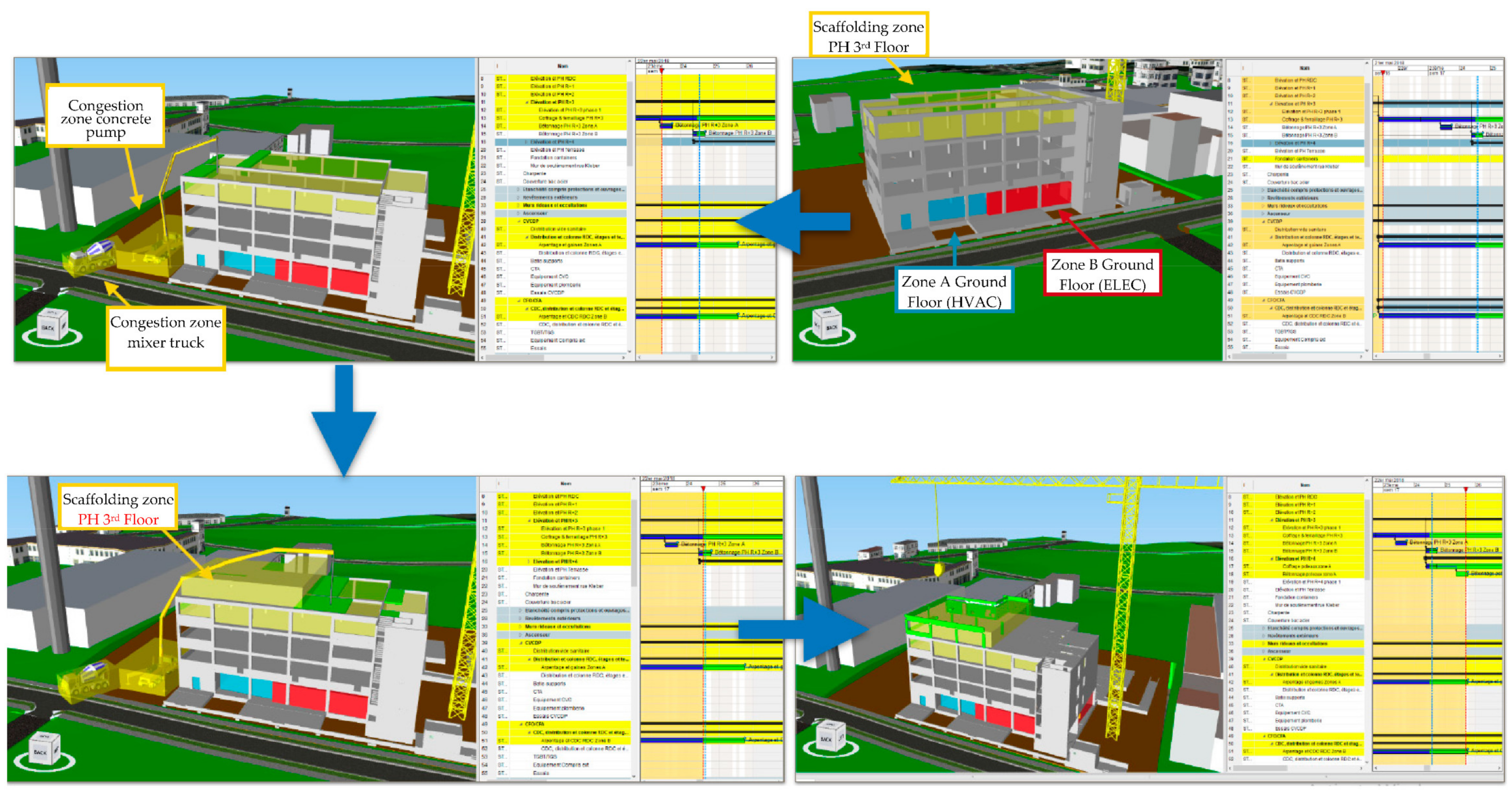
- Site analysis including temporary components such as equipment movement, resource availability, the management of congestion, and other operational constraints. Construction project productivity can be decreased by about 65% due to space congestion [82]. For instance, Huang et al. [29] proposed the integration of construction virtual prototyping systems with 4D models to provide realistic graphical simulations that incorporate both the layout and dynamic analysis of the construction site.
- (ii)
- Spatial conflict detection and workspace congestion avoidance. Chavada et al. [83] analysed conflict detection between workspaces using a 4D BIM visualization of construction schedules. Moon et al. [17] developed an active simulation system based on 4D models and an optimisation process to minimise the simultaneous interference level of the schedule workspace. Trebbe et al. [84] explored the use of 4D models to coordinate different construction engineering designs, schedules, and the operations of contractors on a real railway station renovation project.
- (iii)
- The monitoring of onsite construction work progress with site layout designs. Tran et al. [85] explored the use of 4D BIM and a visual programming language to develop a conceptual framework of camera planning that enables the monitoring of construction site progress. To detect deviations in the construction process between the actual state of a construction and its planned state, Braun et al. [86] proposed an automated framework based on photogrammetric surveys and 4D BIM models.
- (iv)
- The production of short-term work plans. Sriprasert and Dawood [87] implemented a visual multi-constraints planning framework based on the use of 4D BIM and Lean methodology principles. The LEWIS system enables the integration of construction-related information and constraints with 4D planning to ensure the generation of constraint-free commitment work plans.
- (v)
- Spatial–temporal analysis for health and safety management. To prevent construction accidents, Tran et al. [30] proposed a hazard identification approach based on spatial–temporal conflicts that may lead to accidents using 4D BIM models. Han et al. [88] proposed the 3D-CES system to design, verify and simulate the 3D visualisation of mobile crane operation. To assist in elaborating the crane lift schedule, this system enables the identification of safety and productivity aspects while selecting the most efficient crane operation. Tan et al. [89] investigated the use of BIM and 4D acoustics simulation tools to mitigate the noise impact on maintenance workers of offshore platforms. In this framework, the BIM model was used as a source of information, whereas the 4D acoustics approach was used to provide the spatial–temporal sound pressure level distribution of the generated noise;
- (vi)
- Evacuation path planning. Kim et al. [32] proposed a 4D-BIM-based framework that automatically analyses, generates, and visualises the evacuation paths of workers. The prototype developed takes into account construction activities and site constraints to enable the identification of accessible evacuation paths considering customised parameters, such as workspaces, temporary structures, and storage areas.
- (vii)
- Logistics management. For example, to facilitate the visualisation and analysis of construction progress and workspace logistics, Golparvar-Fard et al. [90] proposed the use of 4D photographs. Said and El-Rayes [91] developed an automated multi-objective construction logistics optimisation system to integrate and optimise material supply and site layout decisions. Chin et al. [92] proposed a framework to support the logistics and progress management of structural steel works by using 4D with radio frequency identification technology.
- (viii)
- Augmented vehicle tracking and transportation route planning. Chen and Nguyen [33] investigated the use of BIM with a web map service for selecting between construction material sources. The BIM–WMS decision-making system developed was based on the evaluation of the final cost, material delivery time, and location credits to help designers and project managers in the selection of materials, and cost and schedule planning.
- (ix)
- Construction waste management. Hewage and Porwal [93] proposed a 4D-BIM-based framework in order to predict material waste and propose recycling strategies in construction. Won and Cheng [94] developed a 4D BIM construction waste estimation system which relies on construction waste factors for the estimation of waste generation. Bakchan et al. [95] presented a theoretical 4D BIM solution for construction waste disposal scheduling. However, according to Guera et al. [34], existing 4D BIM applications for construction waste management present some deficiencies, such as only focusing on waste generated by rework activities, a lack of estimation for off-site recycling, and/or the use of fixed factors. To overcome these issues, they proposed the integration of temporal-based algorithms with 4D BIM and demonstrated the proposed solution on two different case studies located in North America for the case of concrete and drywall waste reuse and recycling planning [34].
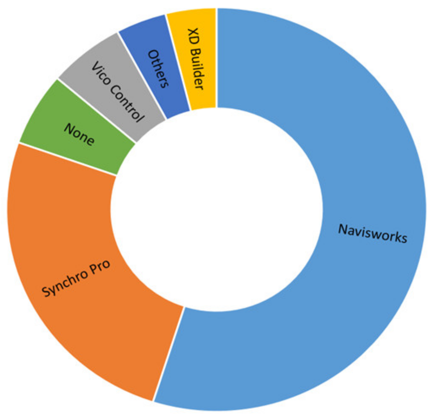
3.2. 4D BIM Tools and Methods Used in France
3.3. Summary of the Identified Problems
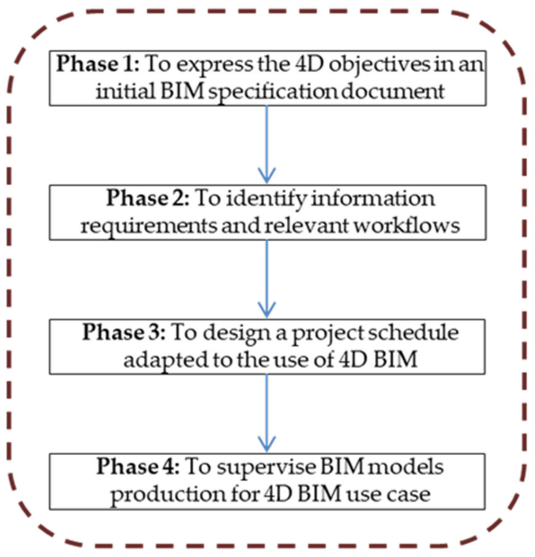
4. A New Proposed Methodology for 4D BIM Planning: The CESI Process
4.1. Phase 1: To Express the 4D Objectives in an Initial BIM Specification Document
- The contractor’s response to the invitation to tender must include 4D planning of construction methods for the works in a visual form that demonstrates its feasibility.
- The appointed contractor’s BIM manager is responsible for the provision of a 4D schedule for the construction phase and its submission to the client. This must allow for progress monitoring of the works at any time during their execution and include the work of all the project delivery team.
- The contractor’s 4D planning solution must enable the identification of all co-contracting zones during the progress of the works with the objective of ensuring and optimising the safety of the site staff and operatives of the companies involved in the works.
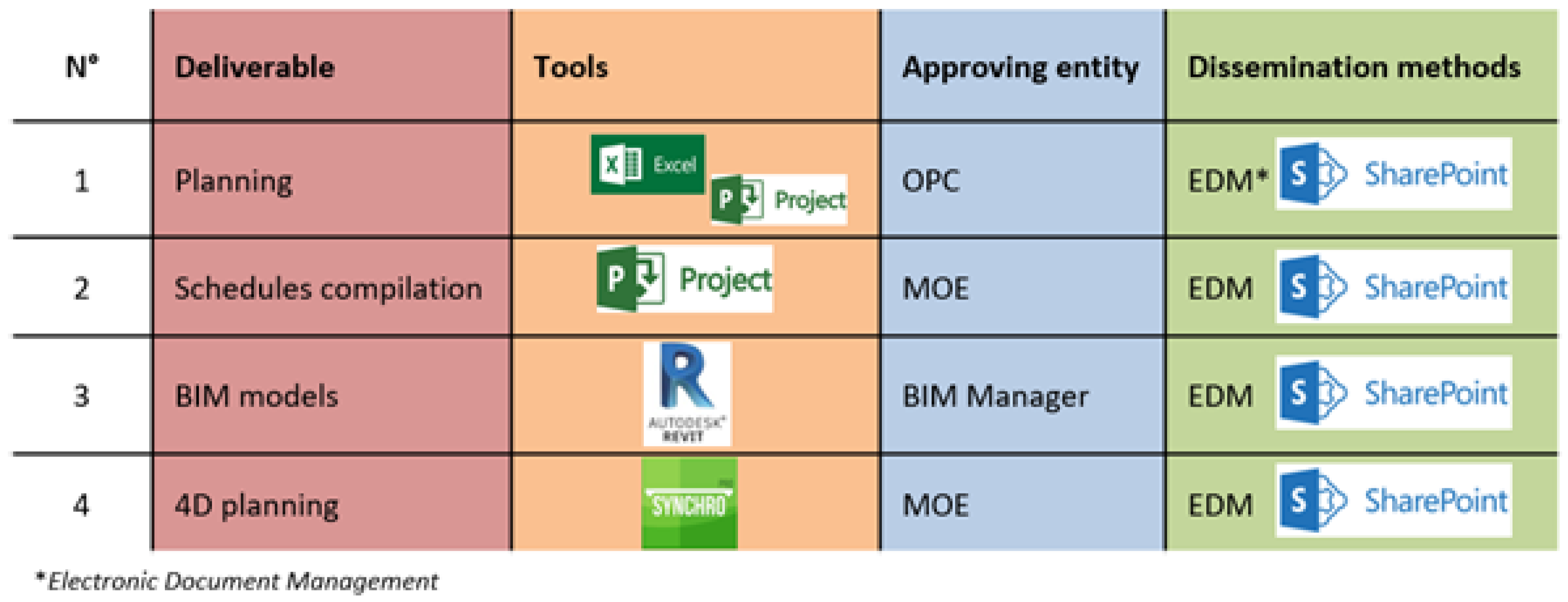
4.2. Phase 2: To Identify Information Requirements and Relevant Workflows
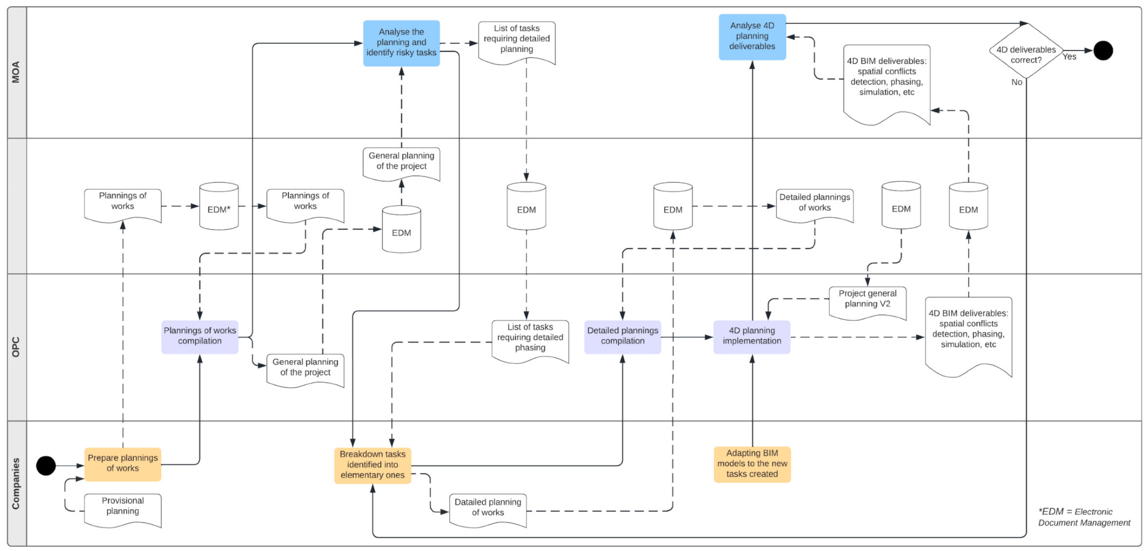
4.3. Phase 3: To Design a Project Schedule Adapted to the Use of 4D BIM
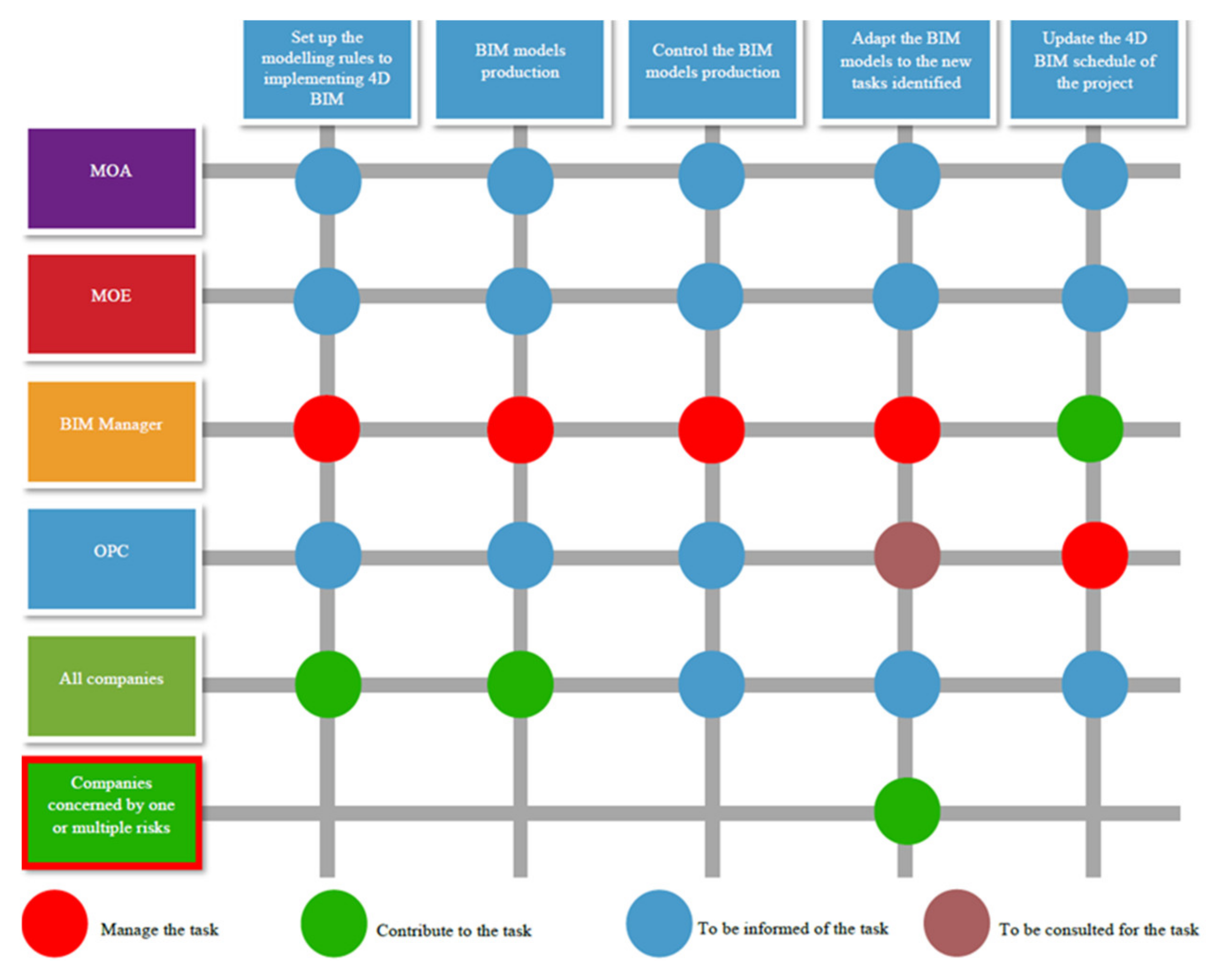
4.4. Phase 4: To Supervise BIM Models Production for 4D BIM Use Case
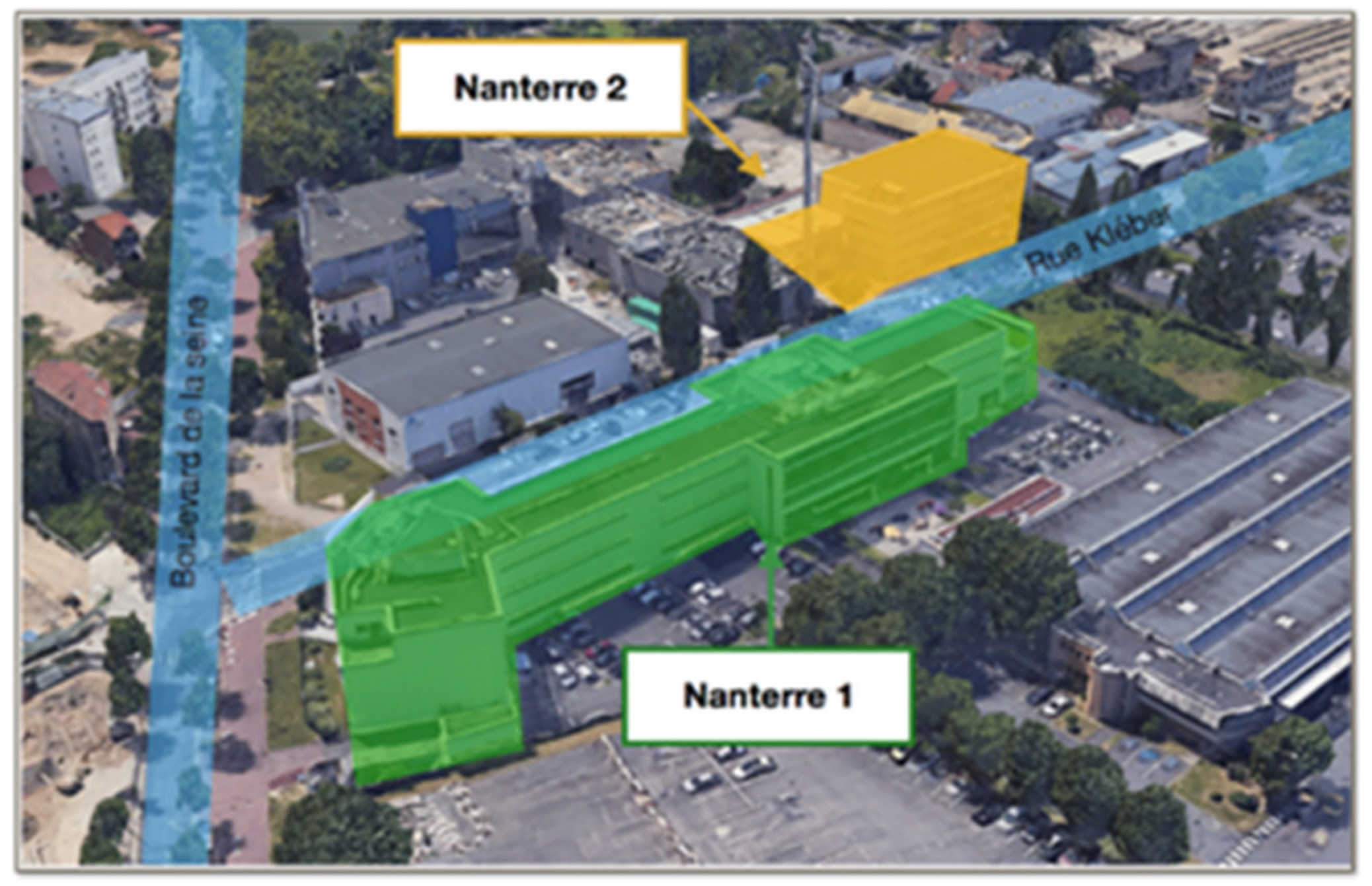
5. Case Study of the Nanterre 2 CESI Project
5.1. Nanterre 2 CESI Project
- Site modelling;
- Project communication;
- Project review;
- Analytical studies *;
- 4D BIM*;
- 5D BIM* (an application integrating the model with cost management activities);
- Management of design conflicts and clashes;
- Logistics support *;
- Regulatory compliance checking;
- Management of construction works and equipment *
5.2. Application and Illustration
5.2.1. Phase 1: To Express the 4D Objectives in an Initial BIM Specification Document
5.2.2. Phase 2: To Identify Information Requirements and Relevant Workflows
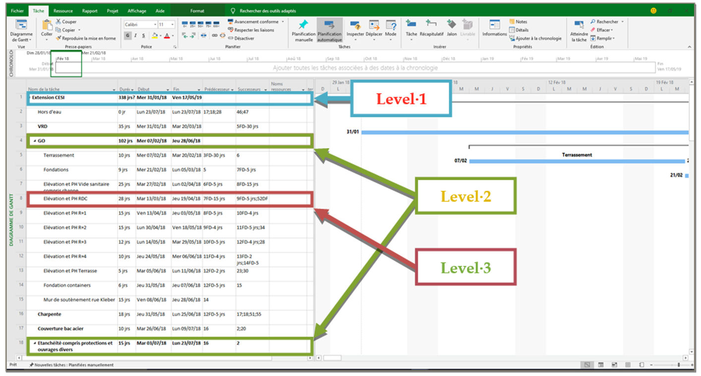
5.2.3. Phase 3: To Design a Project Schedule Adapted to the Use of 4D BIM
5.2.4. Phase 4: To Supervise BIM Models Production for 4D BIM Use Case
5.3. 4D BIM Planning Implementation
5.3.1. Primary 4D BIM Planning
5.3.2. 4D BIM Planning According to the CESI Method
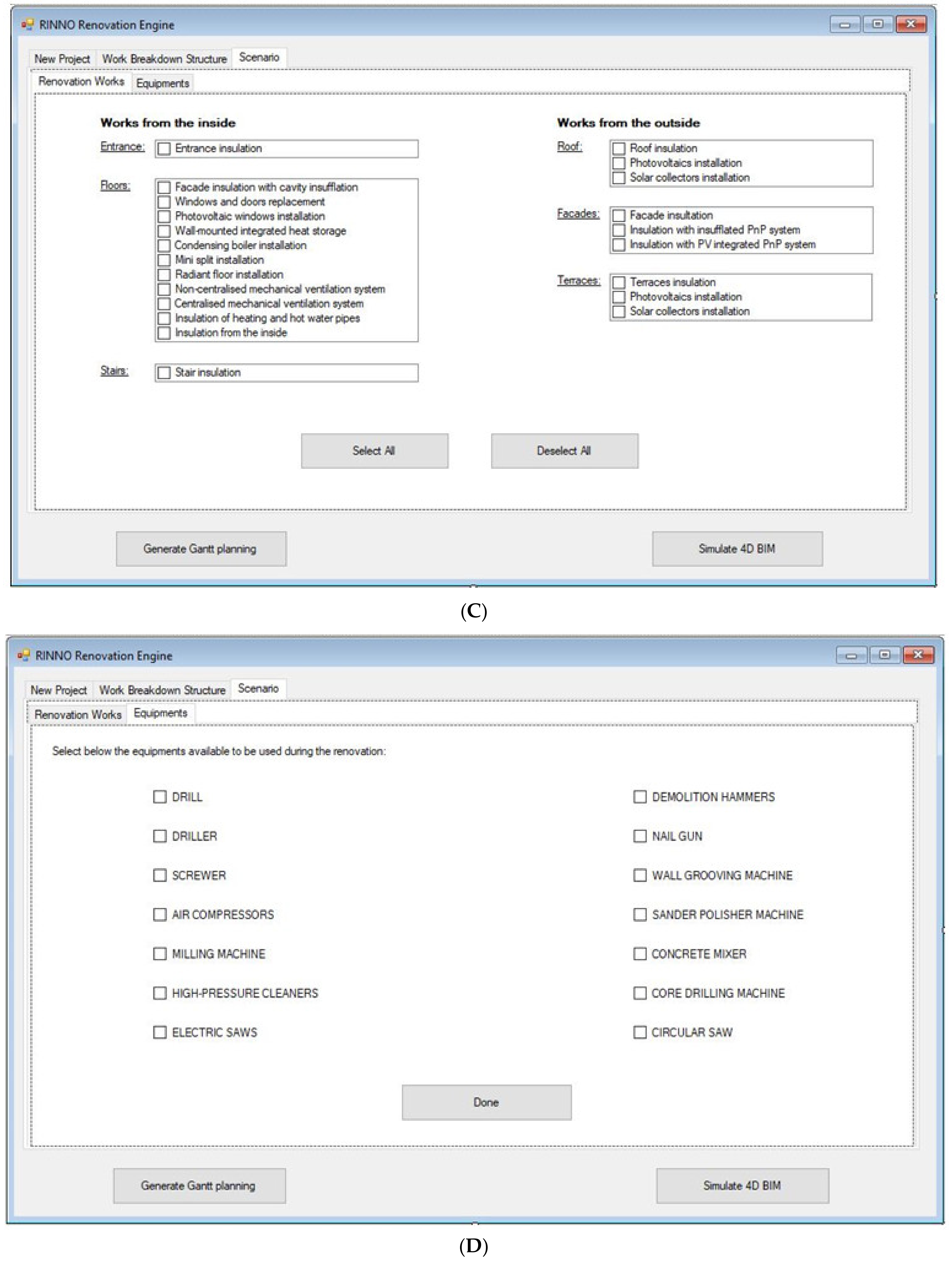
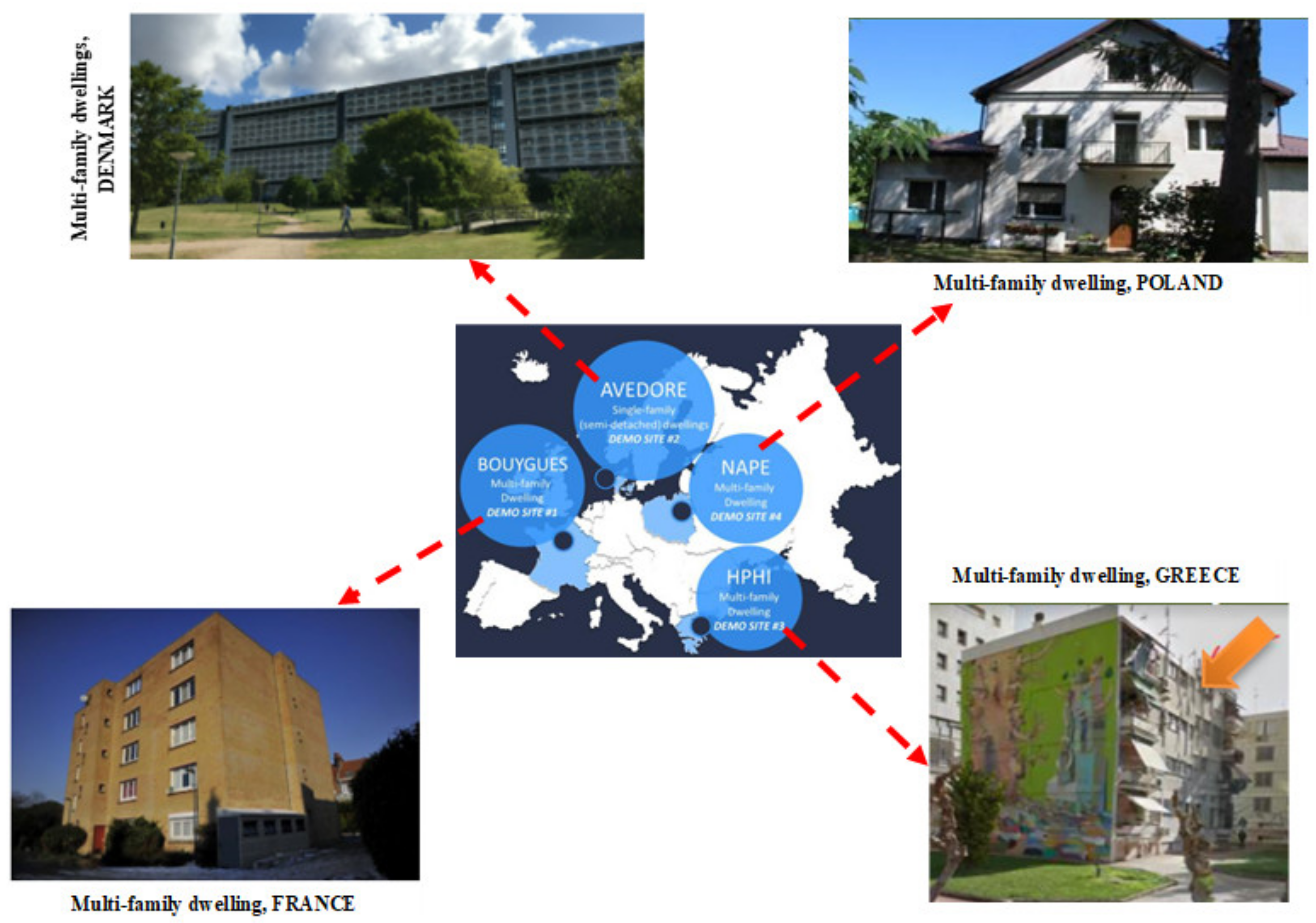
6. Automating 4D BIM Planning: The RINNO Case Study
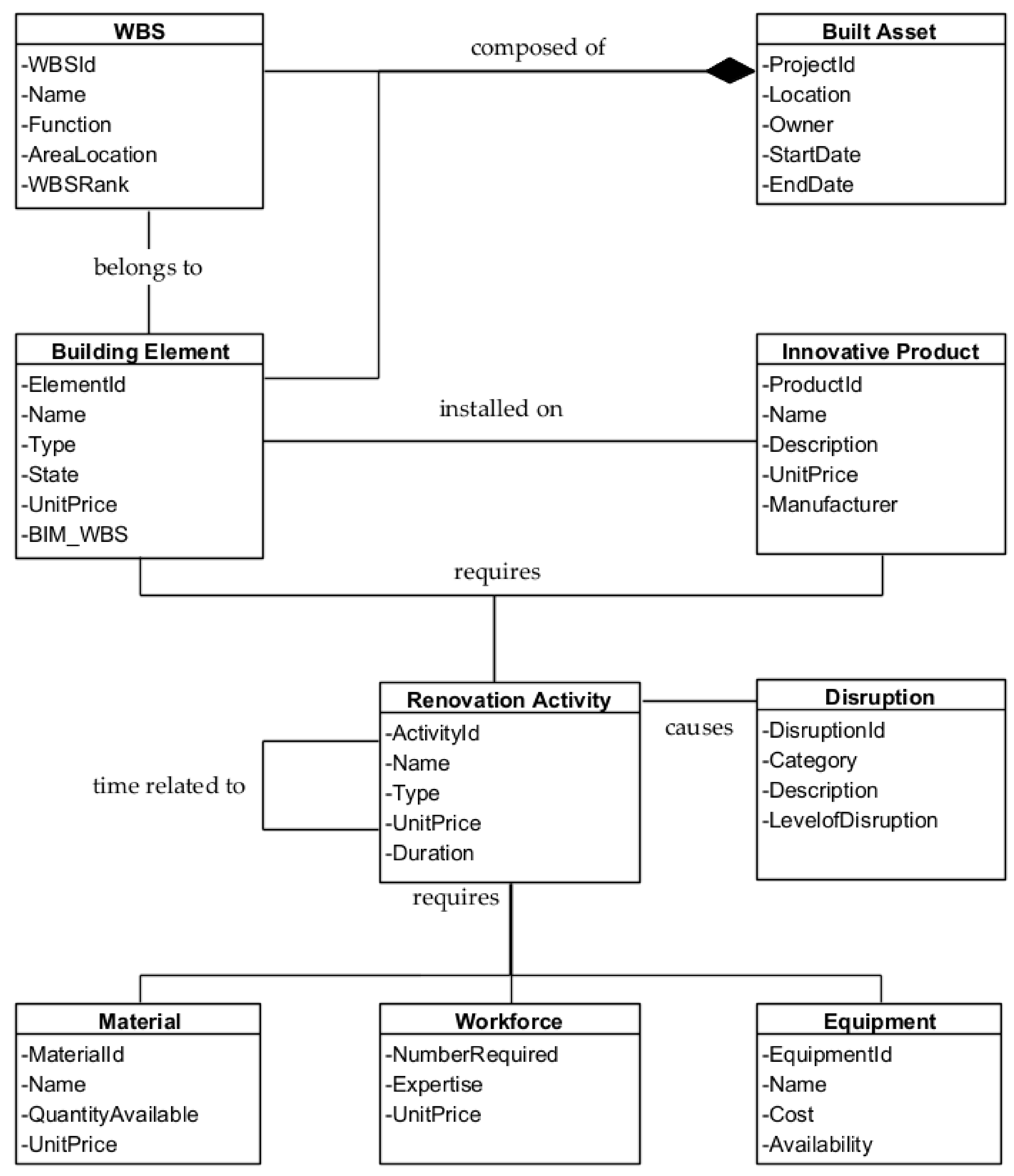
6.1. Renovation 4D Planning Ontology
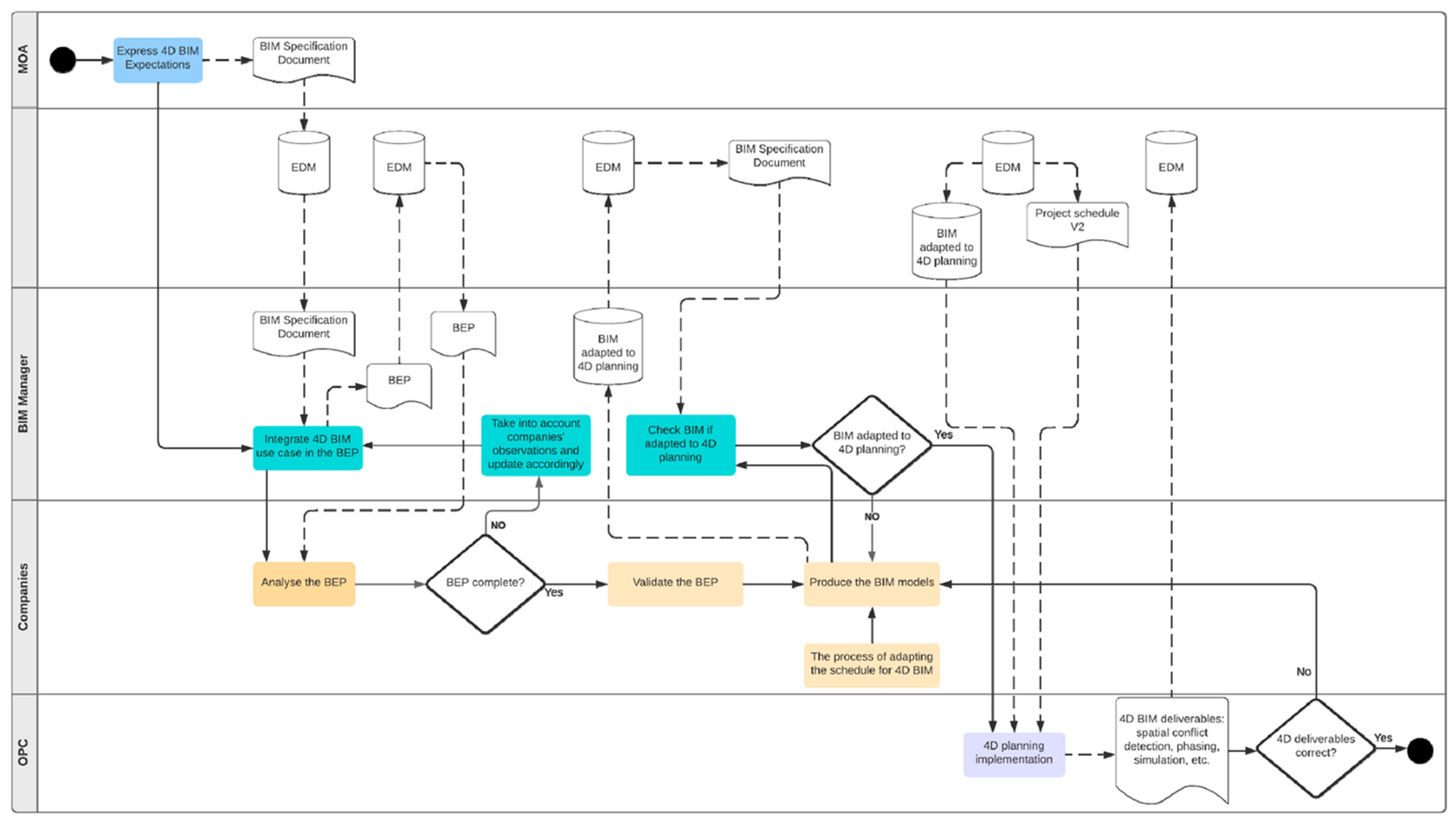
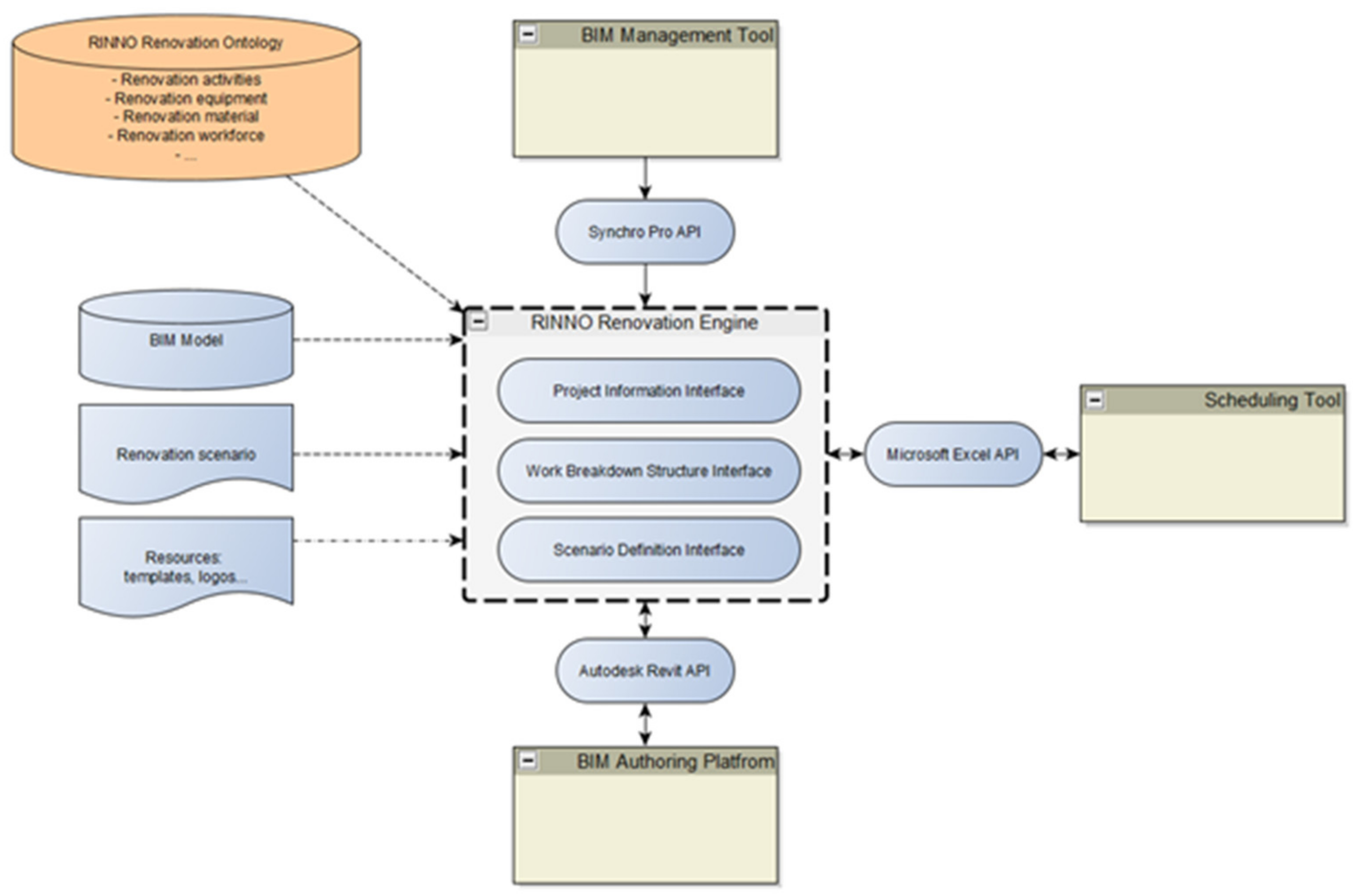
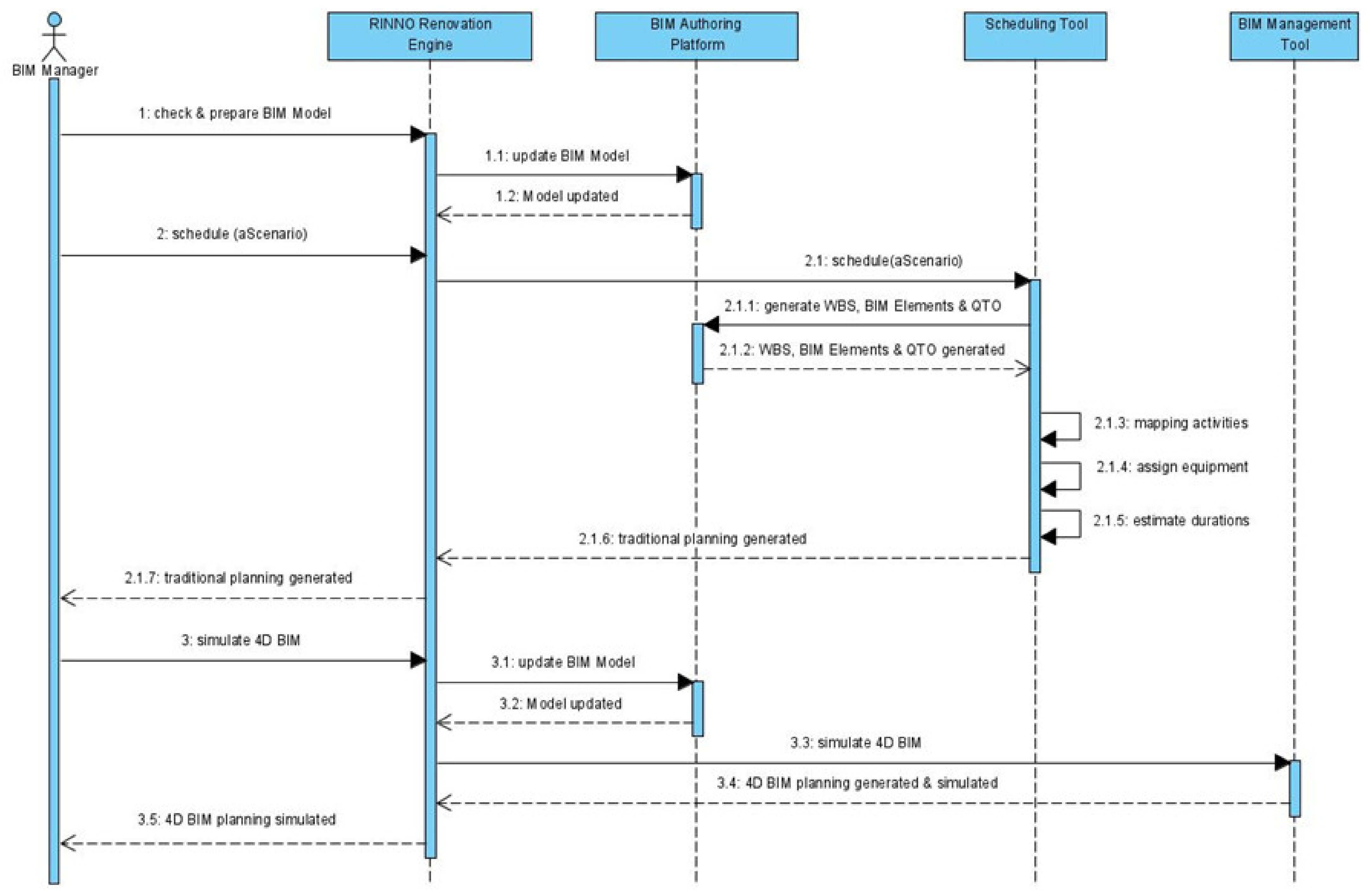
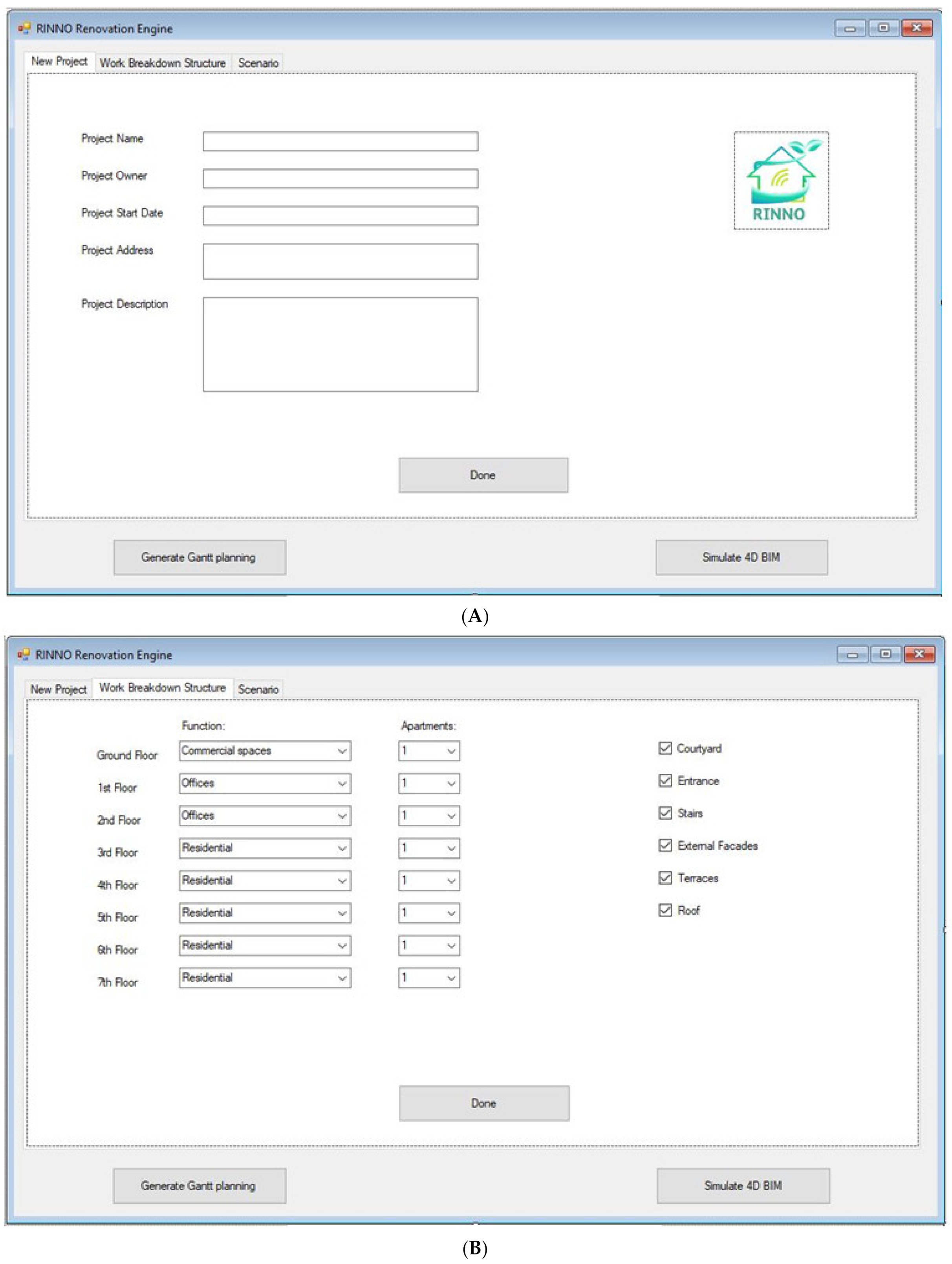
6.2. Automated 4D BIM Planning and Simulation Process
7. Discussion, Conclusions, and Perspectives
7.1. The Nanterre 2 CESI Project Case Study
7.2. The RINNO Project Case Study
Author Contributions
Funding
Institutional Review Board Statement
Informed Consent Statement
Data Availability Statement
Acknowledgments
Conflicts of Interest
Appendix A

| French Role | Abbreviation | English Equivalent |
|---|---|---|
| Maitre d’ouvrage | MOA | Client, Employer, Owner |
| Maitre d’œuvre | MOE | [varies] Client’s Representative, Project Manager, Architect, Engineer |
| Assistant à la maitrise d’ouvrage | AMO | On-site assistant to the above |
| Ordonnancement, planning, coordination | OPC | Consultant planning specialist [unusual in UK context] |
| Coordinateur santé et protection de la sécurité | CSPS | Health and Safety consultant. Planning supervisor. |
| Assistant à la maitrise d’ouvrage BIM | AMO (BIM) | BIM Manager |
References
- Cavka, H.B.; Staub-French, S.; Poirier, E.A. Developing Owner Information Requirements for BIM-Enabled Project Delivery and Asset Management. Autom. Constr. 2017, 83, 169–183. [Google Scholar] [CrossRef]
- Buisman, A. How Are Engineering and Construction Companies Adapting Digital to Their Businesses; Ernst&Young: London, UK, 2018. [Google Scholar]
- Camacho, A.; Cañizares, P.C.; Estévez, S.; Núñez, M. A Tool-Supported Framework for Work Planning on Construction Sites Based on Constraint Programming. Autom. Constr. 2018, 86, 190–198. [Google Scholar] [CrossRef]
- Conlin, J.; Retik, A. The Applicability of Project Management Software and Advanced IT Techniques in Construction Delays Mitigation. Int. J. Proj. Manag. 1997, 15, 107–120. [Google Scholar] [CrossRef]
- Importance of Scheduling in Construction Projects. Available online: https://theconstructor.org/construction/const-management/importance-scheduling-construction-projects/1710/ (accessed on 22 April 2022).
- Egwim, C.N.; Alaka, H.; Toriola-Coker, L.O.; Balogun, H.; Sunmola, F. Applied Artificial Intelligence for Predicting Construction Projects Delay. Mach. Learn. Appl. 2021, 6, 100166. [Google Scholar] [CrossRef]
- Chen, G.-X.; Shan, M.; Chan, A.P.C.; Liu, X.; Zhao, Y.-Q. Investigating the Causes of Delay in Grain Bin Construction Projects: The Case of China. Int. J. Constr. Manag. 2019, 19, 1–14. [Google Scholar] [CrossRef]
- Aravindhan, C.; Santhoshkumar, R.; Bonny, K.; Vidhya, K.; Manishankar, S.; Dhamodharam, P. Delay Analysis in Construction Project Using Primavera & SPSS. Mater. Today Proc. 2021, 7, 186. [Google Scholar] [CrossRef]
- Robinson, T.G. Global Construction Market to Grow $8 Trillion by 2030: Driven by China, US and India; Global Construction Perspectives and Oxford Economics: London, UK, 2015; p. 44. [Google Scholar]
- Flyvbjerg, B. What You Should Know about Megaprojects and Why: An Overview. Proj. Manag. J. 2014, 45, 6–19. [Google Scholar] [CrossRef]
- Chen, S.-M.; Chen, P.-H.; Chang, L.-M. Simulation and Analytical Techniques for Construction Resource Planning and Scheduling. Autom. Constr. 2012, 21, 99–113. [Google Scholar] [CrossRef]
- Yogesh, G.; Hanumanth Rao, C. A Study on Linear Scheduling Methods in Road Construction Projects. Mater. Today Proc. 2021, 47, 5475–5478. [Google Scholar] [CrossRef]
- Gondia, A.; Siam, A.; El-Dakhakhni, W.; Nassar, A.H. Machine Learning Algorithms for Construction Projects Delay Risk Prediction. J. Constr. Eng. Manag. 2020, 146, 04019085. [Google Scholar] [CrossRef]
- Sacks, R.; Eastman, C.; Lee, G.; Teicholz, P. BIM Handbook: A Guide to Building Information Modeling for Owners, Designers, Engineers, Contractors, and Facility Managers, 3rd ed.; Wiley: Hoboken, NJ, USA, 2018; ISBN 978-1-119-28753-7. [Google Scholar]
- Dashti, M.S.; RezaZadeh, M.; Khanzadi, M.; Taghaddos, H. Integrated BIM-Based Simulation for Automated Time-Space Conflict Management in Construction Projects. Autom. Constr. 2021, 132, 103957. [Google Scholar] [CrossRef]
- Bortolini, R.; Formoso, C.T.; Viana, D.D. Site Logistics Planning and Control for Engineer-to-Order Prefabricated Building Systems Using BIM 4D Modeling. Autom. Constr. 2019, 98, 248–264. [Google Scholar] [CrossRef]
- Moon, H.; Dawood, N.; Kang, L. Development of Workspace Conflict Visualization System Using 4D Object of Work Schedule. Adv. Eng. Inform. 2014, 28, 50–65. [Google Scholar] [CrossRef]
- Popov, V.; Juocevicius, V.; Migilinskas, D.; Ustinovichius, L.; Mikalauskas, S. The Use of a Virtual Building Design and Construction Model for Developing an Effective Project Concept in 5D Environment. Autom. Constr. 2010, 19, 357–367. [Google Scholar] [CrossRef]
- American Institute of Architects. G202-2013 Project BIM Protocol; AIA: Columbia, SC, USA, 2013. [Google Scholar]
- Koutamanis, A. Dimensionality in BIM: Why BIM Cannot Have More than Four Dimensions? Autom. Constr. 2020, 114, 103153. [Google Scholar] [CrossRef]
- Ding, L.; Zhou, Y.; Akinci, B. Building Information Modeling (BIM) Application Framework: The Process of Expanding from 3D to Computable ND. Autom. Constr. 2014, 46, 82–93. [Google Scholar] [CrossRef]
- Staub-French, S.; Khanzode, A. 3D and 4D Modeling for Design and Construction Coordination: Issues and Lessons Learned. Electron. J. Inf. Technol. Constr. 2007, 12, 381–407. [Google Scholar]
- Mazars, T.; Francis, A. Chronographical Spatiotemporal Dynamic 4D Planning. Autom. Constr. 2020, 112, 103076. [Google Scholar] [CrossRef]
- Mesároš, P.; Smetanková, J.; Mandičák, T. The Fifth Dimension of BIM—Implementation Survey. IOP Conf. Ser. Earth Environ. Sci. 2019, 222, 012003. [Google Scholar] [CrossRef]
- Charef, R.; Alaka, H.; Emmitt, S. Beyond the Third Dimension of BIM: A Systematic Review of Literature and Assessment of Professional Views. J. Build. Eng. 2018, 19, 242–257. [Google Scholar] [CrossRef]
- Sheikhkhoshkar, M.; Pour Rahimian, F.; Kaveh, M.H.; Hosseini, M.R.; Edwards, D.J. Automated Planning of Concrete Joint Layouts with 4D-BIM. Autom. Constr. 2019, 107, 102943. [Google Scholar] [CrossRef]
- Antwi-Afari, M.F.; Li, H.; Pärn, E.A.; Edwards, D.J. Critical Success Factors for Implementing Building Information Modelling (BIM): A Longitudinal Review. Autom. Constr. 2018, 91, 100–110. [Google Scholar] [CrossRef]
- Zhou, Y.; Ding, L.; Wang, X.; Truijens, M.; Luo, H. Applicability of 4D Modeling for Resource Allocation in Mega Liquefied Natural Gas Plant Construction. Autom. Constr. 2015, 50, 50–63. [Google Scholar] [CrossRef]
- Huang, T.; Kong, C.W.; Guo, H.L.; Baldwin, A.; Li, H. A Virtual Prototyping System for Simulating Construction Processes. Autom. Constr. 2007, 16, 576–585. [Google Scholar] [CrossRef]
- Tran, S.V.-T.; Khan, N.; Lee, D.; Park, C. A Hazard Identification Approach of Integrating 4D BIM and Accident Case Analysis of Spatial–Temporal Exposure. Sustainability 2021, 13, 2211. [Google Scholar] [CrossRef]
- Sloot, R.N.F.; Heutink, A.; Voordijk, J.T. Assessing Usefulness of 4D BIM Tools in Risk Mitigation Strategies. Autom. Constr. 2019, 106, 102881. [Google Scholar] [CrossRef]
- Kim, K.; Lee, Y.-C. Automated Generation of Daily Evacuation Paths in 4D BIM. Appl. Sci. 2019, 9, 1789. [Google Scholar] [CrossRef]
- Chen, P.-H.; Nguyen, T.C. A BIM-WMS Integrated Decision Support Tool for Supply Chain Management in Construction. Autom. Constr. 2019, 98, 289–301. [Google Scholar] [CrossRef]
- Guerra, B.C.; Leite, F.; Faust, K.M. 4D-BIM to Enhance Construction Waste Reuse and Recycle Planning: Case Studies on Concrete and Drywall Waste Streams. Waste Manag. 2020, 116, 79–90. [Google Scholar] [CrossRef]
- Costin, A.; Adibfar, A.; Hu, H.; Chen, S.S. Building Information Modeling (BIM) for Transportation Infrastructure—Literature Review, Applications, Challenges, and Recommendations. Autom. Constr. 2018, 94, 257–281. [Google Scholar] [CrossRef]
- Hosseini, M.R.; Maghrebi, M.; Akbarnezhad, A.; Martek, I.; Arashpour, M. Analysis of Citation Networks in Building Information Modeling Research. J. Constr. Eng. Manag. 2018, 144, 04018064. [Google Scholar] [CrossRef]
- Candelario-Garrido, A.; García-Sanz-Calcedo, J.; Reyes Rodríguez, A.M. A Quantitative Analysis on the Feasibility of 4D Planning Graphic Systems versus Conventional Systems in Building Projects. Sustain. Cities Soc. 2017, 35, 378–384. [Google Scholar] [CrossRef]
- Hartmann, T.; Gao, J.; Fischer, M. Areas of Application for 3D and 4D Models on Construction Projects. J. Constr. Eng. Manag. 2008, 134, 776–785. [Google Scholar] [CrossRef]
- Mahalingam, A.; Kashyap, R.; Mahajan, C. An Evaluation of the Applicability of 4D CAD on Construction Projects. Autom. Constr. 2010, 19, 148–159. [Google Scholar] [CrossRef]
- Blanco, J.L.; Fuchs, S.; Parsons, M.; Ribeirinho, M.J. Artificial Intelligence: Construction Technology’s next Frontier/McKinsey. Available online: https://www.mckinsey.com/business-functions/operations/our-insights/artificial-intelligence-construction-technologys-next-frontier (accessed on 23 April 2022).
- Hartmann, T.; Trappey, A. Advanced Engineering Informatics—Philosophical and Methodological Foundations with Examples from Civil and Construction Engineering. Dev. Built Environ. 2020, 4, 100020. [Google Scholar] [CrossRef]
- Ait-Lamallam, S.; Yaagoubi, R.; Sebari, I.; Doukari, O. Extending the IFC Standard to Enable Road Operation and Maintenance Management through OpenBIM. ISPRS Int. J. Geo-Inf. 2021, 10, 496. [Google Scholar] [CrossRef]
- ISO. ISO 21500: 2021. Available online: https://www.iso.org/cms/render/live/en/sites/isoorg/contents/data/standard/07/57/75704.html (accessed on 16 April 2022).
- Kelley, J.E. Critical-Path Planning and Scheduling: Mathematical Basis. Oper. Res. 1961, 9, 296–320. [Google Scholar] [CrossRef]
- Boton, C. Conception de Vues Métiers Dans Les Collecticiels Orientés Service. Vers Des Multi-Vues Adaptées Pour La Simulation Collaborative 4D/ND de La Construction. Ph.D. Theses, Université de Lorraine, Nancy, France, 2013. [Google Scholar]
- Heaton, J.; Parlikad, A.K.; Schooling, J. Design and Development of BIM Models to Support Operations and Maintenance. Comput. Ind. 2019, 111, 172–186. [Google Scholar] [CrossRef]
- Santana, G. Classification of Construction Projects by Scales of Complexity. Int. J. Proj. Manag. 1990, 8, 102–104. [Google Scholar] [CrossRef]
- Qazi, A.; Quigley, J.; Dickson, A.; Kirytopoulos, K. Project Complexity and Risk Management (ProCRiM): Towards Modelling Project Complexity Driven Risk Paths in Construction Projects. Int. J. Proj. Manag. 2016, 34, 1183–1198. [Google Scholar] [CrossRef]
- Pellerin, R.; Perrier, N. A Review of Methods, Techniques and Tools for Project Planning and Control. Int. J. Prod. Res. 2019, 57, 2160–2178. [Google Scholar] [CrossRef]
- Habibi, F.; Barzinpour, F.; Sadjadi, S.J. Resource-Constrained Project Scheduling Problem: Review of Past and Recent Developments. J. Proj. Manag. 2018, 3, 55–88. [Google Scholar] [CrossRef]
- Sriprasert, E.; Dawood, N. Multi-Constraint Information Management and Visualisation for Collaborative Planning and Control in Construction. J. Inf. Technol. Constr. 2003, 8, 341–366. [Google Scholar]
- Jaafari, A. Criticism of CPM for Project Planning Analysis. J. Constr. Eng. Manag. 1984, 110, 222–233. [Google Scholar] [CrossRef]
- Harris, P.F.; McCaffer, P.R.; Edum-Fotwe, F. Modern Construction Management, 7th ed.; Wiley-Blackwell: Chichester, UK, 2013; ISBN 978-0-470-67217-4. [Google Scholar]
- Line of Balance (LOB). Available online: https://www.designingbuildings.co.uk/wiki/Line_of_balance_(LOB) (accessed on 18 April 2022).
- Mawdesley, M.; Askew, W.; Oreilly, M. Planning & Controlling Construction Projects (Chartered Institute of Building): The Best Laid Plans, 1st ed.; Prentice Hall: Essex, UK, 1997; ISBN 978-0-582-23409-3. [Google Scholar]
- Halpin, D.W.; Martinez, L.-H. Real World Applications of Construction Process Simulation. In Proceedings of the 31st conference on Winter simulation: Simulation—A Bridge to the Future, Association for Computing Machinery, New York, NY, USA, 1 December 1999; Volume 2, pp. 956–962. [Google Scholar]
- Planning and Analysis of Construction Operations/Wiley. Available online: https://www.wiley.com/en-us/Planning+and+Analysis+of+Construction+Operations-p-9780471555100 (accessed on 18 April 2022).
- Martínez, J.C. STROBOSCOPE: State and Resource Based Simulation of Construction Processes. University of Michigan, USA. Available online: https://books.google.co.uk/books?id=xsceAQAAMAAJ (accessed on 18 April 2022).
- Kartam, N.A.; Levitt, R.E.; Wilkins, D.E. Extending Artificial Intelligence Techniques for Hierarchical Planning. J. Comput. Civ. Eng. 1991, 5, 464–477. [Google Scholar] [CrossRef]
- Soman, R.K.; Molina-Solana, M. Automating Look-Ahead Schedule Generation for Construction Using Linked-Data Based Constraint Checking and Reinforcement Learning. Autom. Constr. 2022, 134, 104069. [Google Scholar] [CrossRef]
- Amer, F.; Golparvar-Fard, M. Modeling Dynamic Construction Work Template from Existing Scheduling Records via Sequential Machine Learning. Adv. Eng. Inform. 2021, 47, 101198. [Google Scholar] [CrossRef]
- Jaklinović, K.; Ðurasević, M.; Jakobović, D. Designing Dispatching Rules with Genetic Programming for the Unrelated Machines Environment with Constraints. Expert Syst. Appl. 2021, 172, 114548. [Google Scholar] [CrossRef]
- Amer, F.; Jung, Y.; Golparvar-Fard, M. Transformer Machine Learning Language Model for Auto-Alignment of Long-Term and Short-Term Plans in Construction. Autom. Constr. 2021, 132, 103929. [Google Scholar] [CrossRef]
- McKinney, K.; Fischer, M. Generating, Evaluating and Visualizing Construction Schedules with CAD Tools. Autom. Constr. 1998, 7, 433–447. [Google Scholar] [CrossRef]
- Rolfsen, C.N.; Merschbrock, C. Acceptance of Construction Scheduling Visualizations: Bar-Charts, Flowline-Charts, Or Perhaps BIM? Procedia Eng. 2016, 164, 558–566. [Google Scholar] [CrossRef]
- Retik, A.; Shapira, A. VR-Based Planning of Construction Site Activities. Autom. Constr. 1999, 8, 671–680. [Google Scholar] [CrossRef]
- Sidani, A.; Matoseiro Dinis, F.; Duarte, J.; Sanhudo, L.; Calvetti, D.; Santos Baptista, J.; Poças Martins, J.; Soeiro, A. Recent Tools and Techniques of BIM-Based Augmented Reality: A Systematic Review. J. Build. Eng. 2021, 42, 102500. [Google Scholar] [CrossRef]
- Casini, M. Chapter 9—Advanced Site Management Tools and Methods. In Construction 4.0; Casini, M., Ed.; Woodhead Publishing Series in Civil and Structural Engineering; Woodhead Publishing: Sawston, UK, 2022; pp. 471–521. ISBN 978-0-12-821797-9. [Google Scholar]
- Goldratt, E.M. Critical Chain; North River Press: Great Barrington, MA, USA, 1997; ISBN 978-0-88427-153-6. [Google Scholar]
- Jongeling, R.; Olofsson, T. A Method for Planning of Work-Flow by Combined Use of Location-Based Scheduling and 4D CAD. Autom. Constr. 2007, 16, 189–198. [Google Scholar] [CrossRef]
- Womack, J.P.; Jones, D.T.; Roos, D. The Machine That Changed the World: The Story of Lean Production—Toyota’s Secret Weapon in the Global Car Wars That Is Now Revolutionizing World Industry; Simon and Schuster: New York, NY, USA, 2007; ISBN 978-1-4165-5452-3. [Google Scholar]
- Howell, G.A. What Is Lean Construction? Lean Construction Institute: Arlington, VA, USA, 1999. [Google Scholar]
- Babalola, O.; Ibem, E.O.; Ezema, I.C. Implementation of Lean Practices in the Construction Industry: A Systematic Review. Build. Environ. 2019, 148, 34–43. [Google Scholar] [CrossRef]
- Ballard, H.G. The Last Planner System of Production Control. Ph.D. Thesis, University of Birmingham, Birmingham, UK, 2000. [Google Scholar]
- Murguia, D.; Brioso, X.; Pimentel, A. Applying Lean Techniques to Improve Performance in the Finishing Phase of a Residential Building. In Proceedings of the 24th Annual Conference of the International Group for Lean Construction, Boston, MA, USA, 18–24 July 2016; pp. 43–52. [Google Scholar]
- Adamu, S.; Howell, G.; Abdulhamid, R. Adapting Lean Construction Tecniques in Nigerian Construction Industry. Int. J. Sci. Eng. Res. 2012, 3, 1–11. [Google Scholar]
- Alsehaimi, A.O.; Tzortzopoulos, P.; Koskela, L.J. Last Planner System: Experiences from Pilot Implementation in the Middle East. In Proceedings of the 17th Annual Conference of the International Group for Lean Construction, Taipei, Taiwan, 15–17 July 2009; pp. 53–65. [Google Scholar]
- Alarcón, L.F.; Diethelmand, S.; Rojo, O. Collaborative Implementation of Lean Planning Systems in Chilean Construction Companies. In Proceedings of the Tenth Annual Conference of the International Group for Lean Construction (IGLC-10), Gramado, Brazil, 6–8 August 2002; pp. 1–11. [Google Scholar]
- Sanni-Anibire, M.O.; Mohamad Zin, R.; Olatunji, S.O. Causes of Delay in the Global Construction Industry: A Meta Analytical Review. Int. J. Constr. Manag. 2020, 22, 1395–1407. [Google Scholar] [CrossRef]
- Michalski, A.; Głodziński, E.; Böde, K. Lean Construction Management Techniques and BIM Technology—Systematic Literature Review. Procedia Comput. Sci. 2022, 196, 1036–1043. [Google Scholar] [CrossRef]
- ISO. ISO 19650-1: 2018. Available online: https://www.iso.org/cms/render/live/en/sites/isoorg/contents/data/standard/06/80/68078.html (accessed on 16 April 2022).
- Sanders, S.R.; Thomas, H.R. Factors Affecting Masonry-Labor Productivity. J. Constr. Eng. Manag. 1991, 117, 626–644. [Google Scholar] [CrossRef]
- Chavada, R.; Dawood, N.; Kassem, M. Construction Workspace Management: The Development and Application of a Novel ND Planning Approach and Tool. Electron. J. Inf. Technol. Constr. 2012, 17, 213–236. [Google Scholar]
- Trebbe, M.; Hartmann, T.; Dorée, A. 4D CAD Models to Support the Coordination of Construction Activities between Contractors. Autom. Constr. 2015, 49, 83–91. [Google Scholar] [CrossRef]
- Tran, S.; Ali, A.K.; Khan, N.; Lee, D.; Park, C. A Framework for Camera Planning in Construction Site Using 4D BIM and VPL. ISARC Proc. 2020, 37, 1404–1408. [Google Scholar]
- Braun, A.; Tuttas, S.; Borrmann, A.; Stilla, U. A Concept for Automated Construction Progress Monitoring Using BIM-Based Geometric Constraints and Photogrammetric Point Clouds. J. Inf. Technol. Constr. 2015, 20, 68–79. [Google Scholar]
- Sriprasert, E.; Dawood, N. Next Generation of Construction Planning and Control System: The Lewis Approach. Available online: https://www.semanticscholar.org/paper/NEXT-GENERATION-OF-CONSTRUCTION-PLANNING-AND-SYSTEM-Sriprasert-Dawood/b34eb601bbae61605e89f563449aa3a72f6c019d (accessed on 20 April 2022).
- Han, S.; Bouferguene, A.; Al-Hussein, M.; Hermann, U. (Rick) 3D-Based Crane Evaluation System for Mobile Crane Operation Selection on Modular-Based Heavy Construction Sites. J. Constr. Eng. Manag. 2017, 143, 04017060. [Google Scholar] [CrossRef]
- Tan, Y.; Fang, Y.; Zhou, T.; Gan, V.J.L.; Cheng, J.C.P. BIM-Supported 4D Acoustics Simulation Approach to Mitigating Noise Impact on Maintenance Workers on Offshore Oil and Gas Platforms. Autom. Constr. 2019, 100, 1–10. [Google Scholar] [CrossRef]
- Golparvar-Fard, M.; Peña-Mora, F.; Arboleda, C.A.; Lee, S. Visualization of Construction Progress Monitoring with 4D Simulation Model Overlaid on Time-Lapsed Photographs. J. Comput. Civ. Eng. 2009, 23, 391–404. [Google Scholar] [CrossRef]
- Said, H.; El-Rayes, K. Automated Multi-Objective Construction Logistics Optimization System. Autom. Constr. 2014, 43, 110–122. [Google Scholar] [CrossRef]
- Chin, S.; Yoon, S.; Choi, C.; Cho, C. RFID+4D CAD for Progress Management of Structural Steel Works in High-Rise Buildings. J. Comput. Civ. Eng. 2008, 22, 74–89. [Google Scholar] [CrossRef]
- Hewage, K. Sustainable Construction: An Information Modelling Approach for Waste Reduction. In Proceedings of the International Conference on Building Resilience, Kandalama, Sri Lanka, 19–21 July 2011. [Google Scholar]
- Won, J.; Cheng, J.C.P. Identifying Potential Opportunities of Building Information Modeling for Construction and Demolition Waste Management and Minimization. Autom. Constr. 2017, 79, 3–18. [Google Scholar] [CrossRef]
- Bakchan, A.; Guerra, B.C.; Faust, K.M.; Leite, F. BIM-Based Estimation of Wood Waste Stream: The Case of an Institutional Building Project. In Computing in Civil Engineering 2019: Visualization, Information Modeling, and Simulation; American Society of Civil Engineers: Reston, VA, USA, 2019; pp. 185–192. [Google Scholar] [CrossRef]
- Hardin, B.; McCool, D. BIM and Construction Management: Proven Tools, Methods, and Workflows, 2nd ed.; Wiley: Hoboken, NJ, USA, 2015; ISBN 978-1-118-94276-5. [Google Scholar]
- Gebrehiwet, T.; Luo, H. Analysis of Delay Impact on Construction Project Based on RII and Correlation Coefficient: Empirical Study. Procedia Eng. 2017, 196, 366–374. [Google Scholar] [CrossRef]
- Sriprasert, E.; Dawood, N. Genetic Algorithms for Multi-Constraint Scheduling: An Application for the Construction Industry. In Proceedings of the 20th International Conference on Construction IT: Construction IT Bridging the Distance, Auckland, New Zealand, 23–25 April 2003. [Google Scholar]
- Susanto, N.; Putranto, T.T. Stakeholder Interactions Model of Groundwater Management in Semarang City/Indonesia. Int. J. Geomate 2018, 15, 170–177. [Google Scholar] [CrossRef]
- Amorocho, J.A.P.; Hartmann, T. Reno-Inst: An Ontology to Support Renovation Projects Planning and Renovation Products Installation. Adv. Eng. Inform. 2021, 50, 101415. [Google Scholar] [CrossRef]
- Singh, Y.; Abdelhamid, T.; Mrozowski, T.; El-Gafy, M.A. Investigation of Contemporary Performance Measurement Systems for Production Management of Renovation Projects. J. Constr. Eng. 2014, 2014, 1–9. [Google Scholar] [CrossRef]
- Aldanondo, M.; Barco-Santa, A.; Vareilles, E.; Falcon, M.; Gaborit, P.; Zhang, L. Towards a BIM Approach for a High Performance Renovation of Apartment Buildings. In Product Lifecycle Management for a Global Market; Fukuda, S., Bernard, A., Gurumoorthy, B., Bouras, A., Eds.; Springer: Berlin/Heidelberg, Germany, 2014; pp. 21–30. [Google Scholar]
- Doukari, O.; Lynn, T.; Rosati, P.; Egli, A.; Krinidis, S.; Angelakoglou, K.; Sougkakis, V.; Tzovaras, D.; Kassem, M.; Greenwood, D. RINNO: Transforming Deep Renovation through an Open Renovation Platform. In Proceedings of the ICDS The Fifteenth International Conference on Digital Society, Nice, France, 18–22 July 2021. [Google Scholar]
- Lynn, T.; Rosati, P.; Egli, A.; Krinidis, S.; Angelakoglou, K.; Sougkakis, V.; Tzovaras, D.; Kassem, M.; Greenwood, D.; Doukari, O. RINNO: Towards an Open Renovation Platform for Integrated Design and Delivery of Deep Renovation Projects. Sustainability 2021, 13, 6018. [Google Scholar] [CrossRef]
- Sacks, R.; Koskela, L.; Dave, B.A.; Owen, R. Interaction of Lean and Building Information Modeling in Construction. J. Constr. Eng. Manag. 2010, 136, 968–980. [Google Scholar] [CrossRef]
- Kanan, R.; Elhassan, O.; Bensalem, R. An IoT-Based Autonomous System for Workers’ Safety in Construction Sites with Real-Time Alarming, Monitoring, and Positioning Strategies. Autom. Constr. 2018, 88, 73–86. [Google Scholar] [CrossRef]
- Barlish, K.; Sullivan, K. How to Measure the Benefits of BIM—A Case Study Approach. Autom. Constr. 2012, 24, 149–159. [Google Scholar] [CrossRef]
- Matthews, J.; Love, P.E.D.; Mewburn, J.; Stobaus, C.; Ramanayaka, C. Building Information Modelling in Construction: Insights from Collaboration and Change Management Perspectives. Prod. Plan. Control 2018, 29, 202–216. [Google Scholar] [CrossRef]
- Ilozor, B.; Kelly, D. Building Information Modeling and Integrated Project Delivery in the Commercial Construction Industry: A Conceptual Study. J. Eng. Proj. Prod. Manag. 2012, 2, 23–26. [Google Scholar] [CrossRef]
- Collins, W.; Parrish, K. The Need for Integrated Project Delivery in the Public Sector. In Proceedings of the Construction Research Congress 2014: Construction in a Global Network, Atlanta, GA, USA, 19–21 May 2014; pp. 719–728. [Google Scholar] [CrossRef]
- Vass, S.; Gustavsson, T.K. Challenges When Implementing BIM for Industry Change. Constr. Manag. Econ. 2017, 35, 597–610. [Google Scholar] [CrossRef]
- Stanford University Protégé. Available online: https://protege.stanford.edu/ (accessed on 28 April 2022).
- Designing Buildings Disruption Claims in Construction. Available online: https://www.designingbuildings.co.uk/wiki/Disruption_claims_in_construction (accessed on 17 February 2022).
- Estate Regeneration—Building out Disruption. Available online: http://thoughtleadership.trowers.com/estate-regeneration/building-out-disruption/ (accessed on 17 February 2022).
- Chaves, F.J.; Tzortzopoulos, P.; Formoso, C.T.; Biotto, C.N. Building Information Modelling to Cut Disruption in Housing Retrofit. In Proceedings of the Institution of Civil Engineers-Engineering Sustainability; Thomas Telford Ltd: London, UK, 2017; Volume 170, pp. 322–333. [Google Scholar] [CrossRef]
- Bedrick, J.; Builders, W. Organizing the Development of a Building Information Model. Am. Inst. Archit. 2008, 9, 4. [Google Scholar]
- Leite, F.; Akcamete, A.; Akinci, B.; Atasoy, G.; Kiziltas, S. Analysis of Modeling Effort and Impact of Different Levels of Detail in Building Information Models. Autom. Constr. 2011, 20, 601–609. [Google Scholar] [CrossRef]


| N° | Initial Formulation | SMART Formulation |
|---|---|---|
| 1 | The BIM model must include data related to equipment and temporary structures required for onsite construction works. | The use of 4D BIM must enable visualisation and analysis of space occupation by equipment and temporary structures when two companies work within the same area. |
| 2 | The update of the schedule must be conducted in real time and correspond to the exact progress of onsite construction works. | At any time during the construction phase, 4D BIM planning must enable the measuring of construction work progress within +/−3 days. |
| 4D BIM Objectives | Information to Be Produced |
|---|---|
| The use of 4D BIM must enable visualisation and analysis of space occupations by equipment and temporary structures when two companies work within the same area. |
|
| At any time during the construction phase, 4D BIM planning must enable the measuring of construction work progress within +/- 3 days. |
|
| 4D BIM Objectives | Information to be Produced | Information Identification or Its Location |
|---|---|---|
| The use of 4D BIM must enable visualisation and analysis of space occupations by equipment and temporary structures when two companies work within the same area | Dates and duration of co-contracting periods | Planning |
| Name of the companies concerned | Planning | |
| Nature of the work | Planning | |
| Location of occupied areas | Planning | |
| Dimensions and dimensions of equipment/temporary structures | Planning | |
| Equipment circulation areas | Planning | |
| Equipment type | Planning | |
| At any time during the construction phase, 4D BIM planning must enable the measuring of construction work progress within +/- 3 days. | 4D parameter linked to the schedule | ‘BIM_WBS’: Planning |
| Project task flowchart level | Planning | |
| Nature of the links between the tasks | Planning |
| 4D BIM Objectives | Evaluation |
|---|---|
| The use of 4D BIM must enable visualisation and analysis of space occupations by equipment and temporary structures when two companies work within the same area |
|
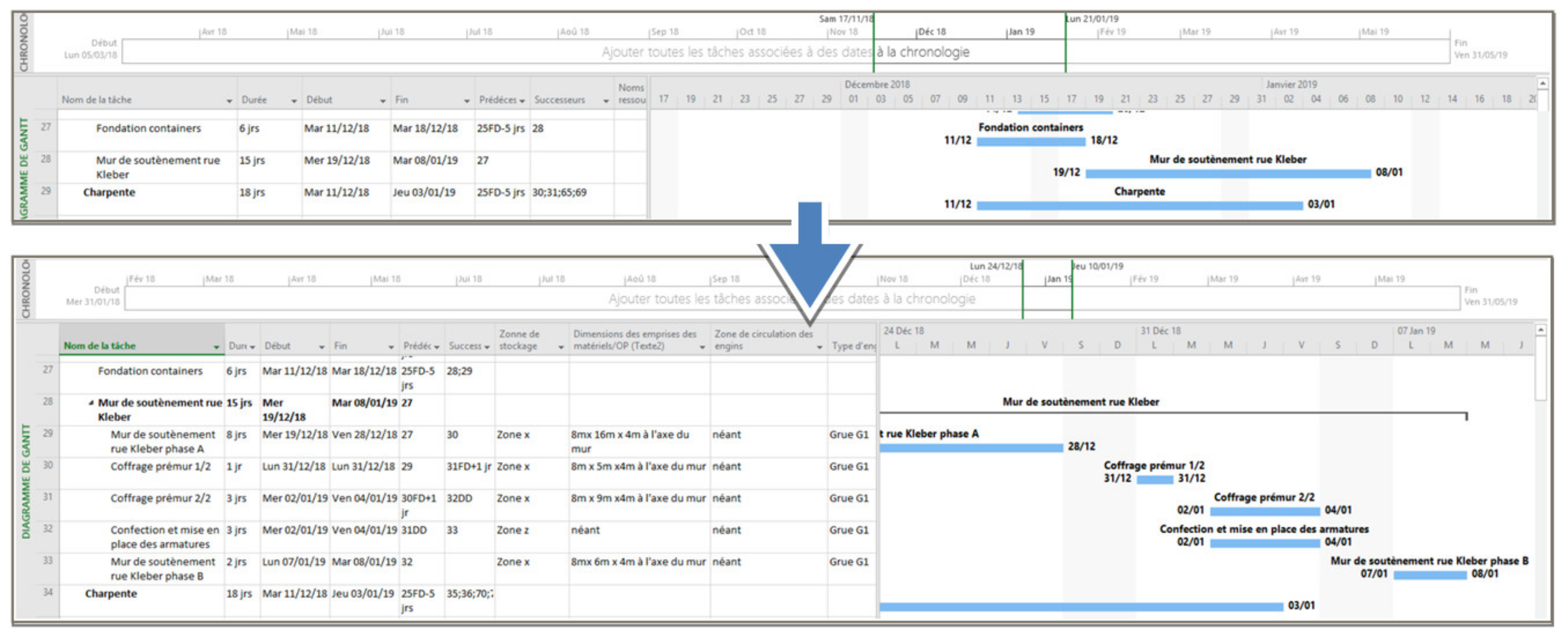
| At any time during the construction phase, 4D BIM planning must enable the measuring of construction work progress within +/−3 days | As shown in Figure 12, the new 4D planning required the creation of new sub-tasks and therefore the increasing of the level of the project tasks flowchart. This makes it possible to specify the exact nature of the work to be carried out and therefore to assess more precisely its progress. |
Publisher’s Note: MDPI stays neutral with regard to jurisdictional claims in published maps and institutional affiliations. |
© 2022 by the authors. Licensee MDPI, Basel, Switzerland. This article is an open access article distributed under the terms and conditions of the Creative Commons Attribution (CC BY) license (https://creativecommons.org/licenses/by/4.0/).
Share and Cite
Doukari, O.; Seck, B.; Greenwood, D. The Creation of Construction Schedules in 4D BIM: A Comparison of Conventional and Automated Approaches. Buildings 2022, 12, 1145. https://doi.org/10.3390/buildings12081145
Doukari O, Seck B, Greenwood D. The Creation of Construction Schedules in 4D BIM: A Comparison of Conventional and Automated Approaches. Buildings. 2022; 12(8):1145. https://doi.org/10.3390/buildings12081145
Chicago/Turabian StyleDoukari, Omar, Boubacar Seck, and David Greenwood. 2022. "The Creation of Construction Schedules in 4D BIM: A Comparison of Conventional and Automated Approaches" Buildings 12, no. 8: 1145. https://doi.org/10.3390/buildings12081145