
Deformation and Force Analysis of Wood-Piled Island Cofferdam Based on Equivalent Bending Stiffness Principle
by
 , ,
, ,
Shi Chen
1, 
Yixian Wang
1,2,*,
Yonghai Li
3,
Xian Li
1,*,
Panpan Guo
1,4,
Weichao Hou
5 and
Yan Liu
2 1
School of Civil Engineering, Hefei University of Technology, Hefei 230009, China
2
State Key Laboratory of Explosion Science and Technology, Beijing Institute of Technology, Beijing 100081, China
3
The Second Engineering Co., Ltd. of CTCE Group, Suzhou 215131, China
4
Research Center of Coastal and Urban Geotechnical Engineering, Zhejiang University, Hangzhou 310058, China
5
China Railway 24th Bureau Group Anhui Engineering Corporation Limited, Hefei 230011, China
*
Authors to whom correspondence should be addressed.
Buildings 2022, 12(8), 1104; https://doi.org/10.3390/buildings12081104
Submission received: 2 July 2022
/
Revised: 20 July 2022
/
Accepted: 23 July 2022
/
Published: 27 July 2022
(This article belongs to the Topic New Trends in Rock Materials Mechanics and Engineering Geology)
Abstract
:This paper analyses the deformation and force behavior of a wood-piled island cofferdam based on the principle of equivalent bending stiffness. The horizontal deformation and bending moments in wood piles and the axial stress in tension bars on top of piles were both analyzed by the finite difference (FD) method. Except for the analysis of the cofferdam construction process, the influence of the pile length, the dam width, the tension bar interval, and the pile interval, among the commonly adopted parameters, were detailly examined in numerical simulations. In addition, a reinforced wood-piled cofferdam model by steel pipe piles has been established to quantify the effect of reinforcement. It was found that the dewatering inside the cofferdam was detrimental to cofferdam stability. The pile deformation reached maxima (roughly 0.6% of the pile length) at solidifying stage after dewatering. The changing trend of the cofferdam structure force within a safe district was consistent with the displacement. The dam width had a vital effect on the stability of the cofferdam, especially on the horizontal deformation. The steel pipe pile reinforcement scheme performed better in further deformation control, providing a new idea for island-type cofferdams with rigorous structural deformation control.
1. Introduction
As an important temporary water blocking facility for water construction, cofferdams are widely applied to build docks, bridge piles, and tunnels [1,2,3]. Commonly used cofferdam structure forms include steel sheet piles, steel pipe piles, earth–rock dams, and wood piles. The construction technology of the steel sheet-pile cofferdam is relatively mature and has a wide range of applicability owing to strong resistance to deformation. However, building a cofferdam comprised of steel sheet piles is costly and requires a long construction period. Therefore, building steel cofferdams in shallow water areas with low water pressure is not economical. As a low-cost construction structure, it is worth exploring whether the wood-piled cofferdam can resist water and soil pressure and maintain its own stability in shallow water areas.
Based on different cofferdam construction backgrounds, numerous studies have been carried out over the last several decades. Arboleda-Monsalve et al. [4] presented two urban cofferdams composed of segmental steel ring beams and concrete ring beams, respectively. The results indicated that the distribution of lateral wall movements differed for both cofferdams due to noticeable differences in the structural configuration. Based on the RMA (reduced modulus action) value from measured data, Wang et al. [5] proposed a strategy for the design of the steel sheet-pile support structure. It was also confirmed that cofferdams installed in the sea face a high risk of structural damage when extreme wave load occurs ([6,7]). In 2009, Gui et al. [8] reported a failed double-wall cofferdam after heavy rainfall. The dislocation of the weld joints directionally caused the failure, warning that an appropriate support system with adequate safety margin and flexibility is vital.
Seepage effect, especially dewatering influence as investigated by Zeng et al. [9], should not be ignored as the cofferdam is exposed to water during its entire construction. This can induce piping or quicksand, detrimental to cofferdam stability. Benmebarek et al. [10] analyzed seepage failure of the sandy soil within a cofferdam subjected to an upward seepage flow. They identified the conditions for seepage failure occurring by boiling or heaving the soil behind sheet piles. Not limited to the sandy soil layer, based on different geological conditions, many scholars (e.g., refs. [11,12,13]) carried out a series of research work on the influence of seepage on the stability of cofferdams. These results indicated seepage affects the cofferdam by changing soil properties around the cofferdam structure. In addition, other issues related to cofferdam reinforcement ([14]) and cofferdam slope stability ([15]) have also received much attention.
Perhaps due to excessive safety considerations, the application of wood-piled cofferdams in large-scale projects is rare, and relevant reports have not been covered. This highlights the necessity to research the structural stability of cofferdams. Unlike other cofferdams, the double-row wood-piled cofferdam utilizes the dam-filling soil and the two rows of piles to form a whole to resist the outer water and soil pressure. This type of cofferdam has advantages in shallow water areas, with readily available raw materials and convenient construction. Especially for island-type cofferdams, the size of the cofferdam is much larger than that of the internal foundation pit, so the excavation of the foundation pit has little effect on the structure of the outer cofferdam, which means that the piles only bear the water and soil pressure above the riverbed.
Based on the principle of equivalent flexural stiffness, as mentioned in some studies [2,16,17], the study presented herein aims to research the stress and deformation behavior of a real cofferdam construction under the fluid–solid coupling effect. A plentiful parametric analysis of the cofferdam structure has also been conducted. In addition, to further reduce the deformation of the wood-piled cofferdam, a construction scheme of using steel pipe piles to reinforce the wood piles is investigated, which provides a new option for the construction of the cofferdam in shallow water areas.
2. Equivalent Bending Stiffness Principle
2.1. Equivalent Representation of the Wood-Pile Cofferdam
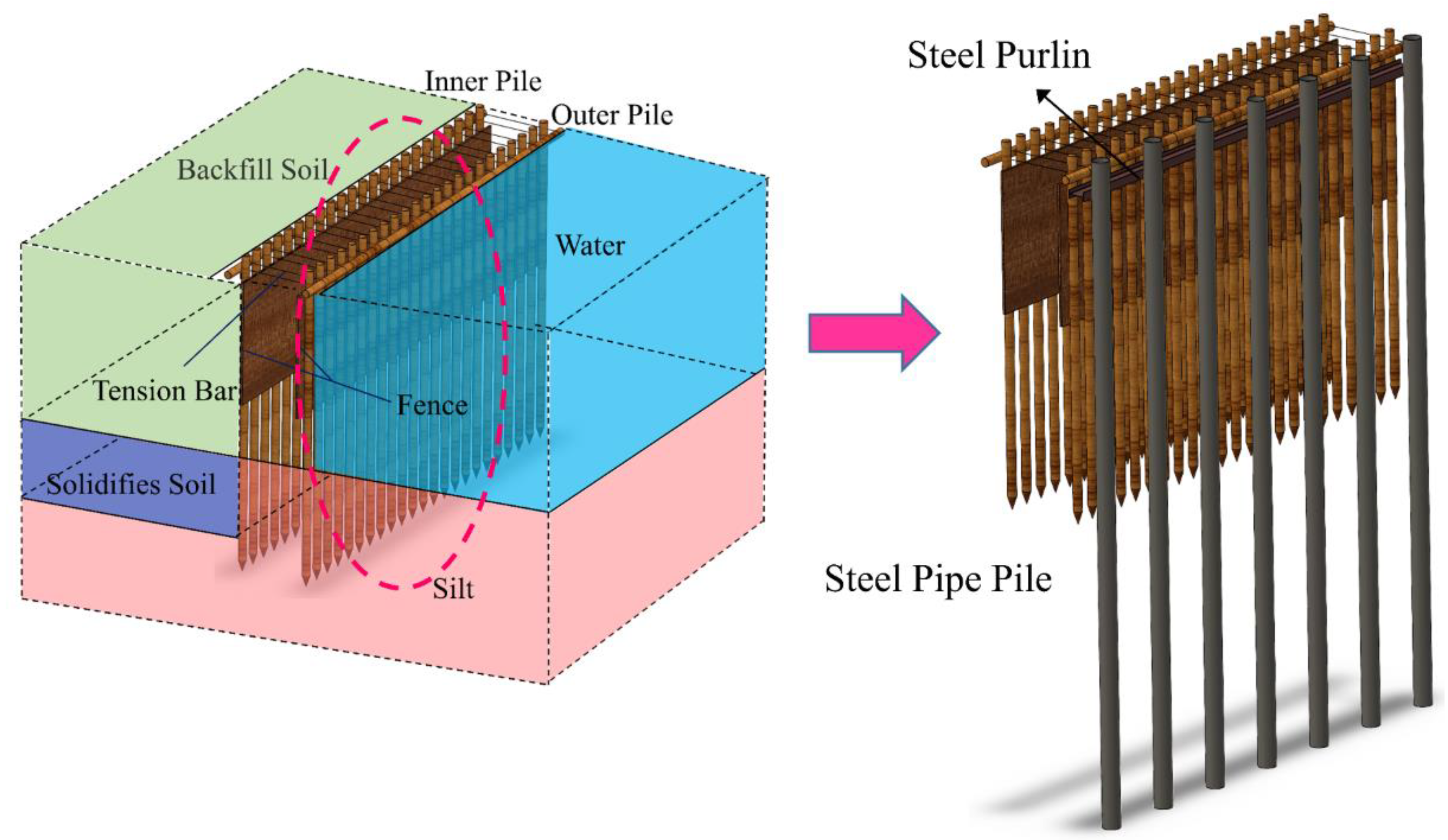
The wood-piled cofferdam relies on two rows of wood piles and the filling between the piles to maintain its stability. The wood piles are inserted into the riverbed, not a continuous structural material like steel sheet piles. Suppose the theoretical analysis and numerical modeling are carried out on each wood-piled structure as the analysis object alone. In that case, the amount of calculation is undoubtedly huge, and some simplifications in the calculation are necessary. Therefore, as shown in Figure 1, the idea of equivalent stiffness is considered in this paper, and the independent wood piles are equivalent to sheet piles. In addition, tension bars for reinforcement are simplified as tension rods, which facilitates the subsequent numerical simulation research.
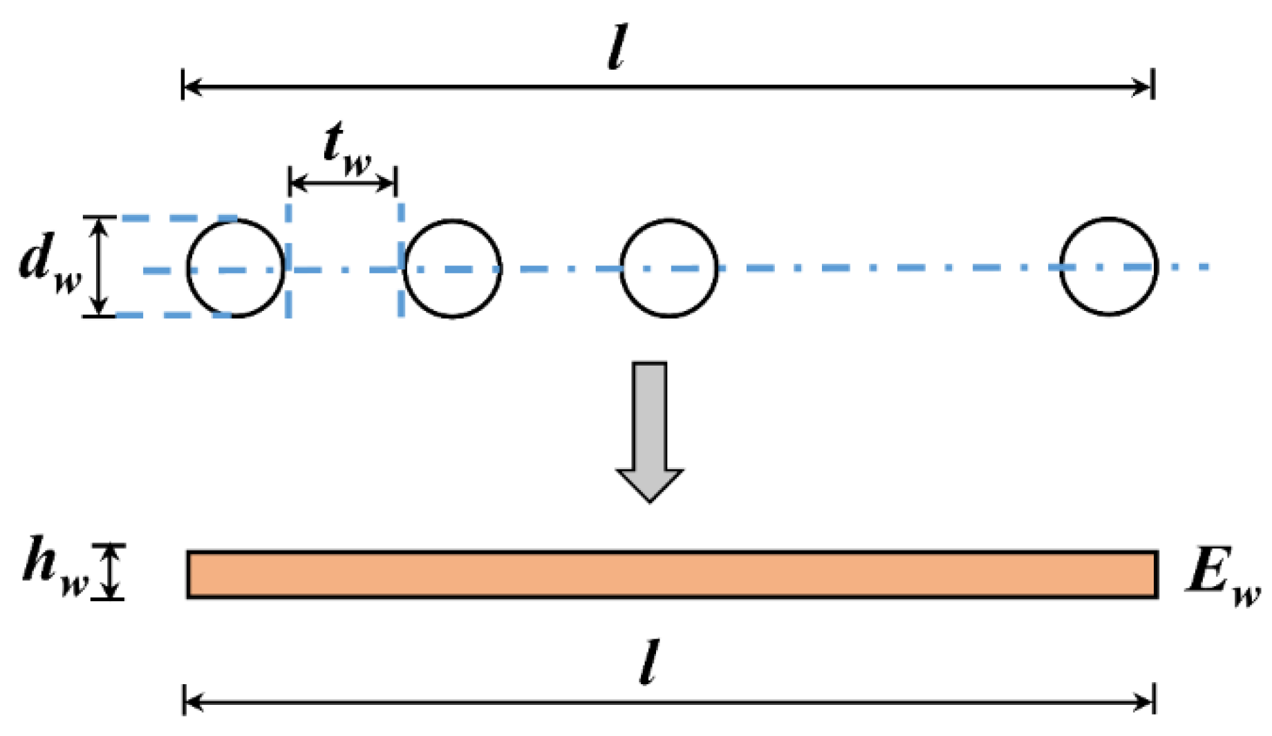
2.2. Equivalent of Wood Piles
In the cofferdam, the double-row pile structure mainly bears the bending moment. As shown in Figure 2, considering the convenience of modeling, the wood piles were converted into sheet piles according to the principle of equal bending stiffness.
The equivalent generation relationship (Equations (1)–(3)) is as follows, where dw is the diameter of wood piles; tw is the interval of two adjacent wood piles; l is the length of the dam calculated; nw is the number of single-row wood piles ‘l’ containing; hw is the equivalent thickness of a single row of stakes; Ew is the stiffness of wood piles; also, Dw and Dh, are, respectively, the equal bending stiffness of stakes and sheet piles.
when Dw = Dh, putting Equation (3) into Equation (2). According to Equation (4), the equivalent thickness of a single row of stakes (hw) is defined as follows:
when tw/nw approaches 0, according to Equation (5), hw can be approximately expressed as follow:
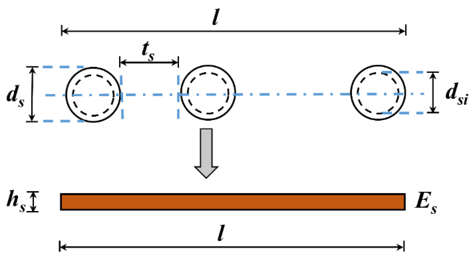
2.3. Equivalent Model of Steel Pipe Pile
The steel pipe pile reinforcement scheme, detailed in Section V, was also accounted for. To simplify the calculation, similar to wood piles, the steel pipe pile is equivalent to a sheet pile with the same stiffness in the numerical model. As shown in Figure 3, according to the principle of equivalent bending stiffness, those hollow tubular piles are equivalent to liner unit with a certain thickness.
Accordingly, Equation (6) shows the solution formula for the equivalent thickness of the steel pipe pile. Where ds is the outer diameter of steel pipe piles; dsi is the inner diameter of steel pipe piles; ts is the interval of two adjacent steel pipe piles; hs is the equivalent thickness of a row of steel pipe piles; and Es is the stiffness of steel pipe piles.
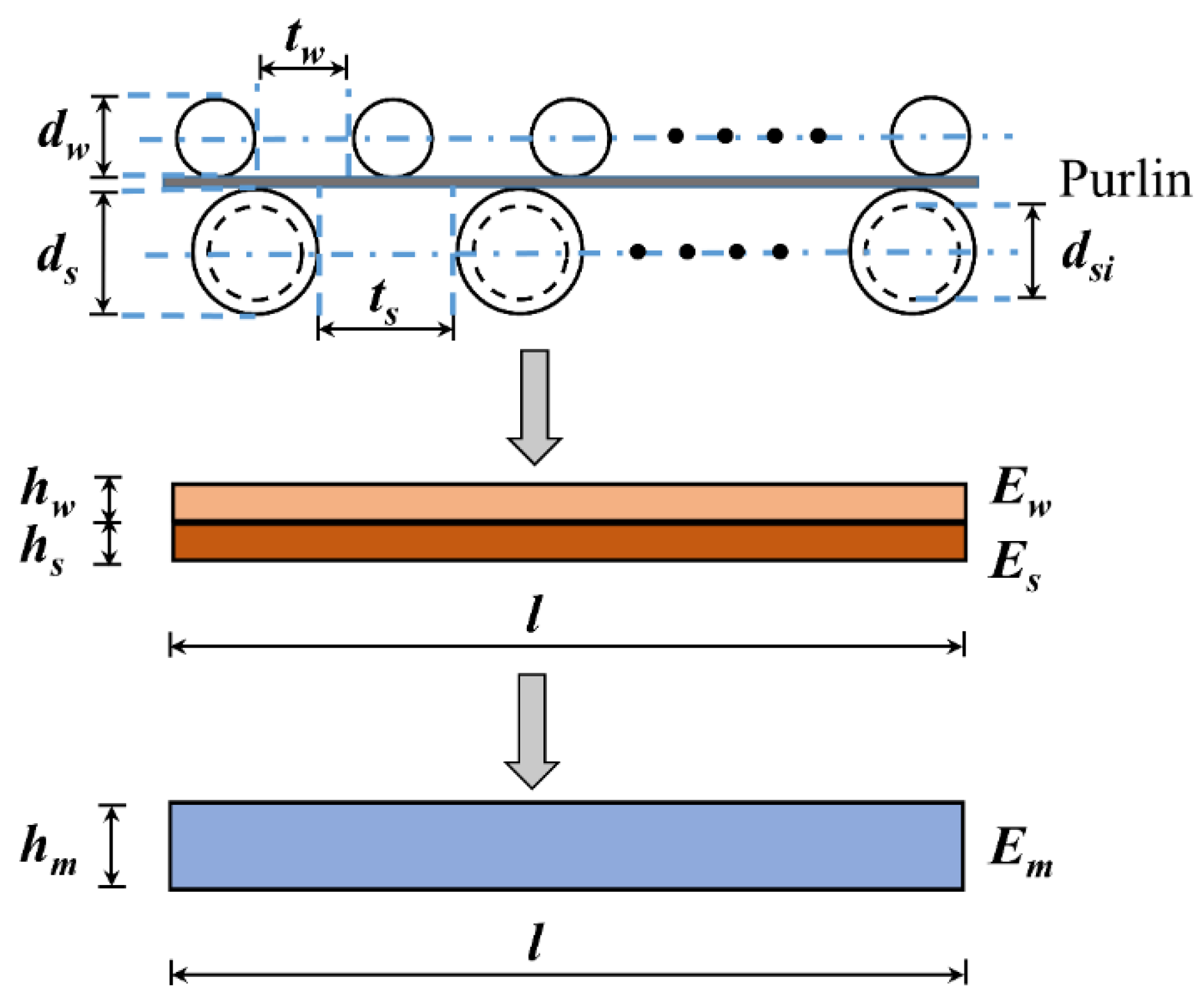
In this numerical model, the lower half of the steel pipe pile can be established with its equivalent thickness. The upper half of the steel pipe pile and the wood-piled cofferdam are combined into an approximate whole, so considering the superposition effect is necessary. The equivalent of the combination of the two is shown in Figure 4, without considering the effect of the steel purlin.
Equation (7) is the equivalent stiffness balance equation of the composite pile. For the convenience of calculation, also expressed in Equation (8), the sum of the two pile thicknesses is set as the equivalent pile thickness. Em (the stiffness of composite piles) is the only unknown parameter.
3. Project Overview
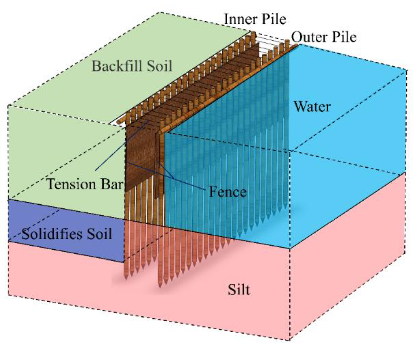
In this study, the cofferdam was built as the land construction platform for the Textile City Bridge demolition and reconstruction project. The Textile City Bridge is located in the beautiful city of Shaoxing, Zhejiang Province, China, the hometown of Lu Xun, a famous Chinese literary master. With the high-speed development of Shaoxing, the bridge built in the 1990s could not meet the busy traffic demand. Thus, demolition and reconstruction work of this bridge was carried out. The dismantling and rebuilding of the arch rib were complex, requiring significant aerial work. Considering the large size of the bridge (200 m in length, 30 m in width) and the convenience of construction, an island-building cofferdam for land construction was necessary, as shown in Figure 5. In addition, the average water level ranges from 3.5 to 4.0 m. Applying the steel cofferdam was not economical and unnecessary. Therefore, constructing a double row wood pile cofferdam instead of steel sheet piles is a better choice in terms of duration and cost. To provide a sufficiently spacious working platform for the demolition and reconstruction of the bridge, the size of the cofferdam built is an approximate square with a side length of 90 m, surrounded by water on three sides and bordering the embankment.
Figure 6 shows the local structure and geology of the double-row wood pile cofferdam. Specifically, the diameter of the wood pile was 0.2 m, and the length was 9.0 m. Three wood piles were driven on the dam body per meter. The width between the two rows of piles was 2.5 m, and the piles were driven into the riverbed at a depth of 4.5 m. To improve the stability of the whole cofferdam, the top of the pile was set with wood piles purlins by the same specification. Purlins on both sides of the dam body were strengthened by φ10 mm threaded steel bars, and the tension bars were installed along the direction of the dam body every 1.0 m. Considering the low permeability coefficient of geomembrane and easy access of silt, the dam body between the two rows of piles was filled with river silt wrapped in geomembrane.
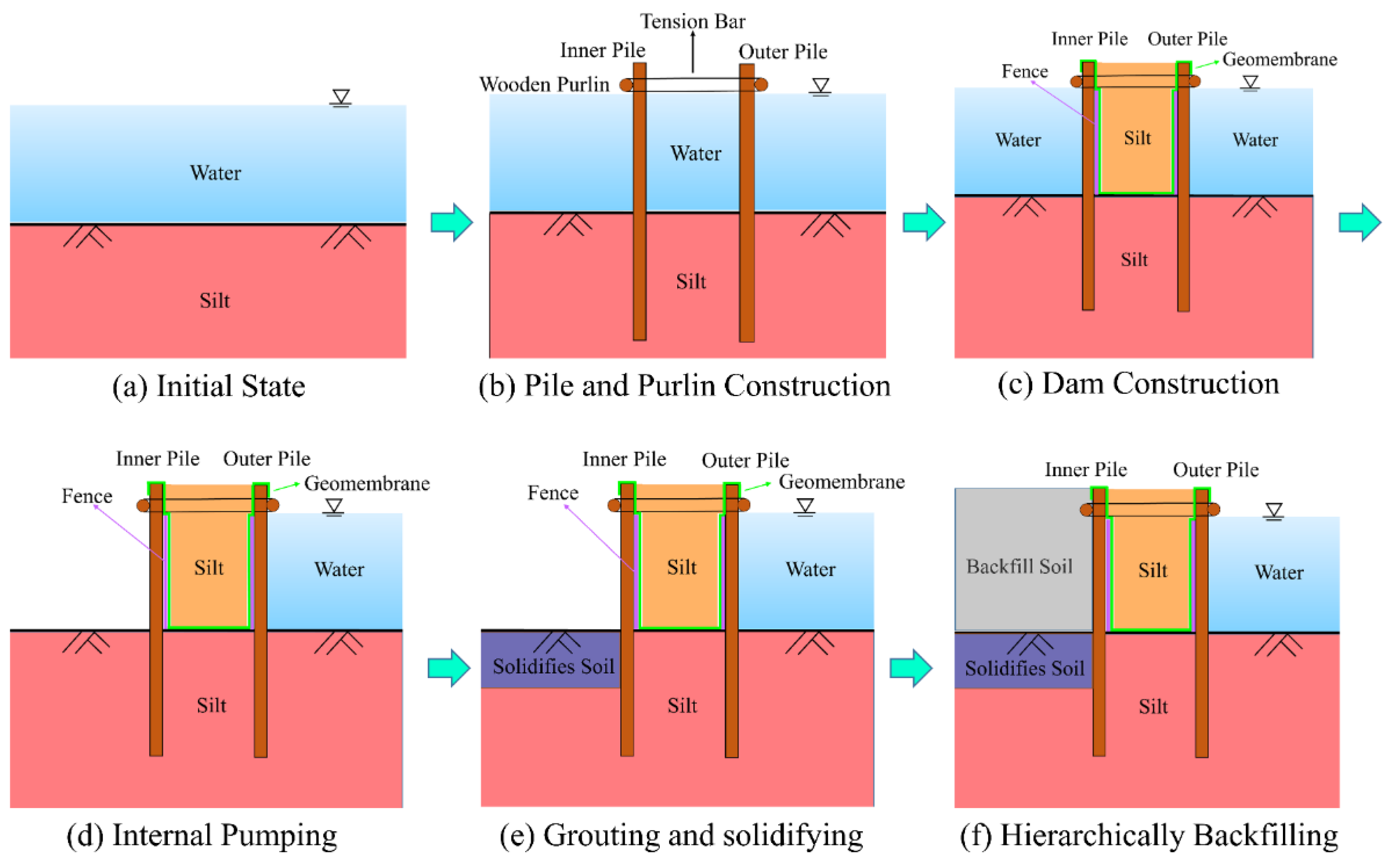
A bamboo fence and geomembrane were installed outside the dam body as critical parts of water resistance. After the completion of the dam construction, dewatering inside the cofferdam could be carried out. Next, the silt foundation would be treated with grouting and solidification at a depth of 2.0 m. Finally, the internal area of the cofferdam was hierarchically filled with soil. The relevant construction steps are displayed in Figure 7.
4. Numerical Analysis
4.1. Model Setup
This section established a three-dimensional simulation model in Fast Lagrangian Analysis software (FLAC3D, ITASCA, Minneapolis, MN, USA), providing a more efficient way of solving the fluid–mechanical interaction problems. Additionally, FLAC3D has been used in many deep excavation and cofferdam projects and proved to be greatly accurate and reliable [18,19].
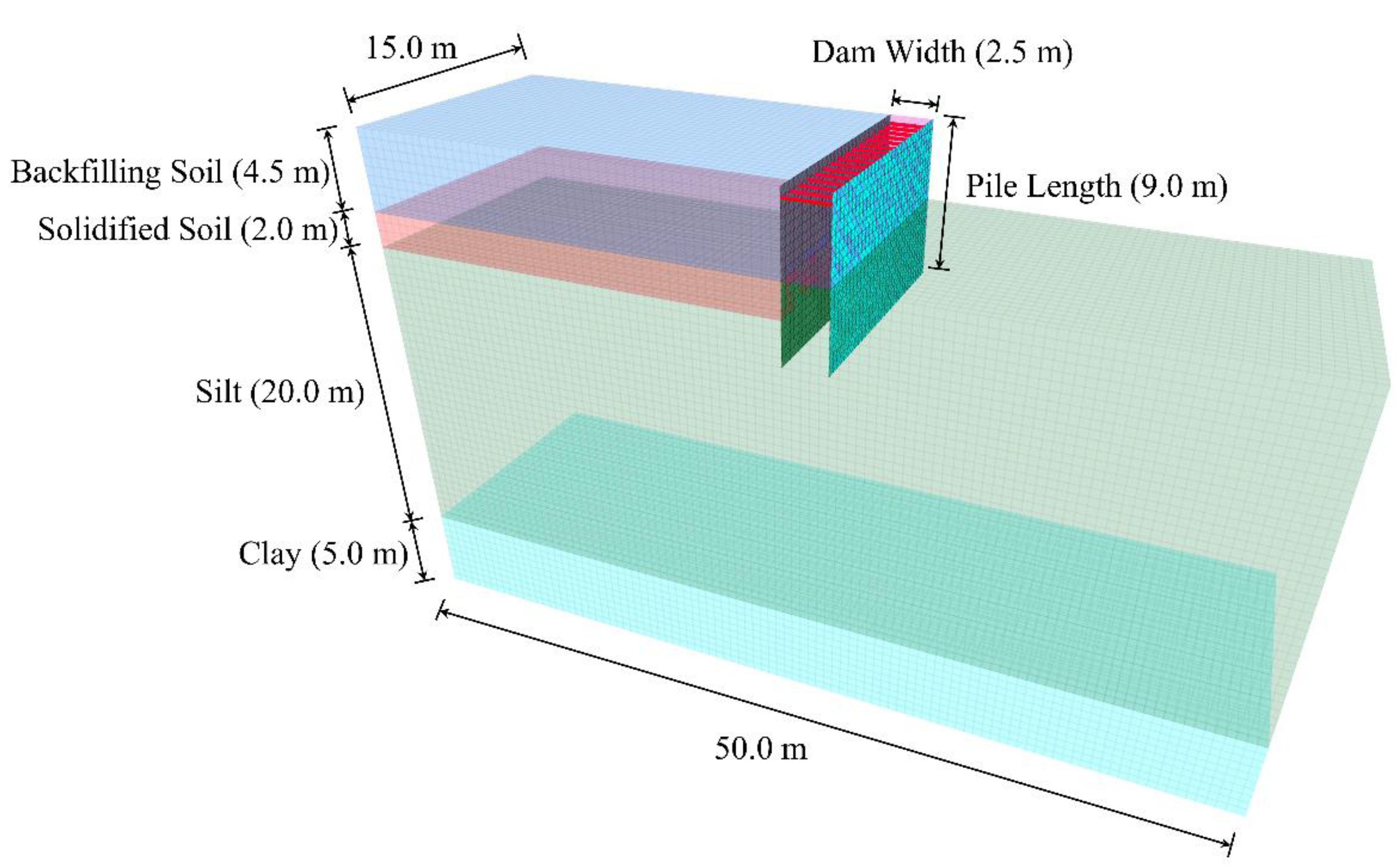
Considering that all sides of the cofferdam have the same specifications, this simulation model could be created in a local three-dimension form to balance computational speed and model accuracy. The wood piles were driven into the riverbed at a depth of 4.5 m. Therefore, the model had set up from a section of the cofferdam with a size of 50.0 m × 15.0 m × 29.5 m (length × width × height). The model involved four layers: silt, clay, solidified soil, and backfilling soil. As clearly shown in Table 1, their constitutive behaviors were described by Mohr–Coulomb models with different parameters. Since the double-row wooden piles were equivalent to two sheet piles with the same bending stiffness, the wood-piled structure was simulated with an elastic liner model. Although wood is an anisotropic material, to facilitate modeling, it was simplified as an isotropic material, taking the flexural modulus of the wood piles as the overall elastic modulus. The tension bars were only withstanding tension force and simplified to elastic cable models. The element type was chosen for other structural components as a solid element.
Figure 8 shows the relative position of the structural elements to the soil layer. Liner element (wood piles), with a height of 9.0 m, its upper part was above the riverbed. Two rows of sheet piles were connected by tension bars, and nodes at connections were shared. The model contained a 25.0 m thick soil layer below the riverbed. The bottom five meters was clay, and silt was located 20.0 m below the riverbed. Although the average water level ranges from 3.5 m to 4.0 m, taking bad conditions into account, the model was based on a water depth of 4.0 m as a reference. Since the flow of the river was very slow, there was no large-scale wind or waves. Only the influence of hydrostatic pressure was considered in the model. The boundary conditions were fixed for the base surface and rollered for the vertical surfaces. Assuming that the geomembrane was intact and impermeable, seepage occurred only outside the dam.
To simplify the calculation, the construction process of the cofferdam was simulated at five stages, as summarized in Table 2. The wood-piled cofferdam built in the river had to consider a seepage field. Thus, the initial seepage-stress balance was calculated at the first stage. It is important to note that the geo-stress initialization assumed that the soil in each layer was homogeneous, continuous, and isotropic. All structure element, including liner and cable, was installed at the second stage. The third stage of dewatering was the key step in constructing the cofferdam, in which piles would bear large bending moments and generate large deformation. The fluid–structure interaction should be considered in this step. After pumping inside the cofferdam, grouting and solidifying work would carry out at a depth of 2.0 m below the riverbed. Accordingly, the parameters of the silt would be replaced by the parameters of the solidified soil within the appropriate scope at stage 4. The final step was to backfill the interior of the cofferdam with miscellaneous filling soil.
4.2. Simulation Results
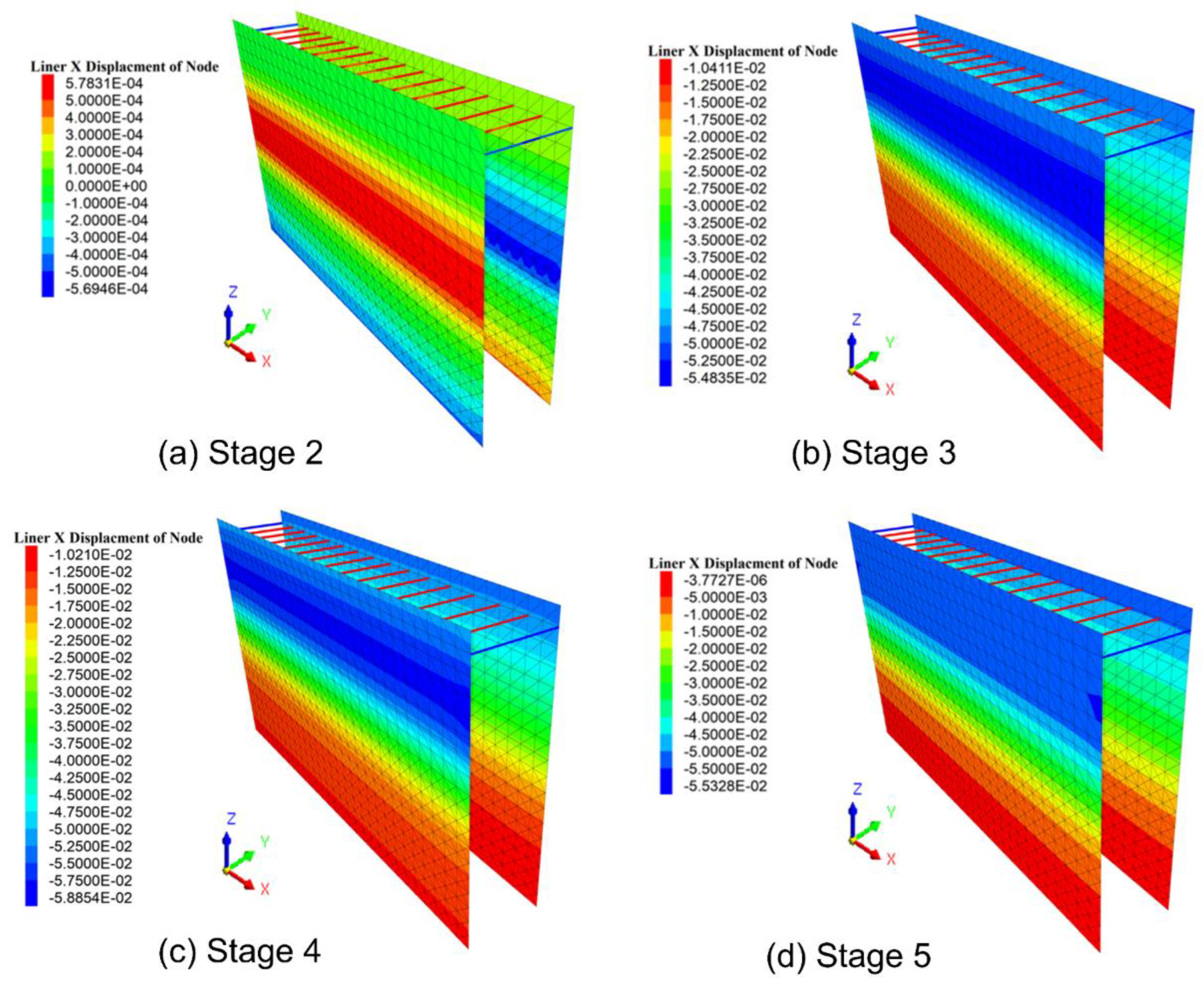
The horizontal displacement cloud picture of the equivalent sheet piles at different construction stages is shown in Figure 9. It could be observed that piles appeared with a large horizontal displacement of 55 mm at stage 3. After pumping, grouting, and solidifying stage 4, it expanded the deformation to 59 mm due to the grouting increasing the lateral stress of the lower piles. In addition, the horizontal deformation of the piles was decreased after the soil filling step, as miscellaneous filling soil balanced out the part earth pressure of the cantilever piles. It should be noted that the maximum horizontal displacement of outer piles was at the top position. However, the inner piles occurred at a position of 1.5 m below the pile top.
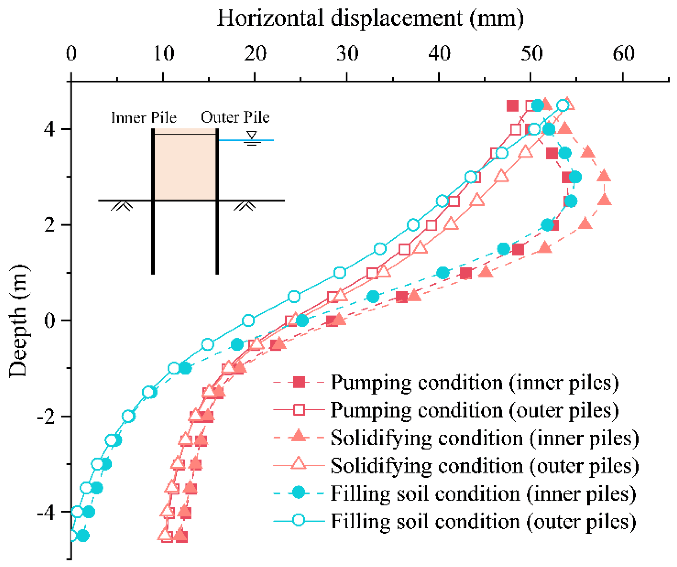
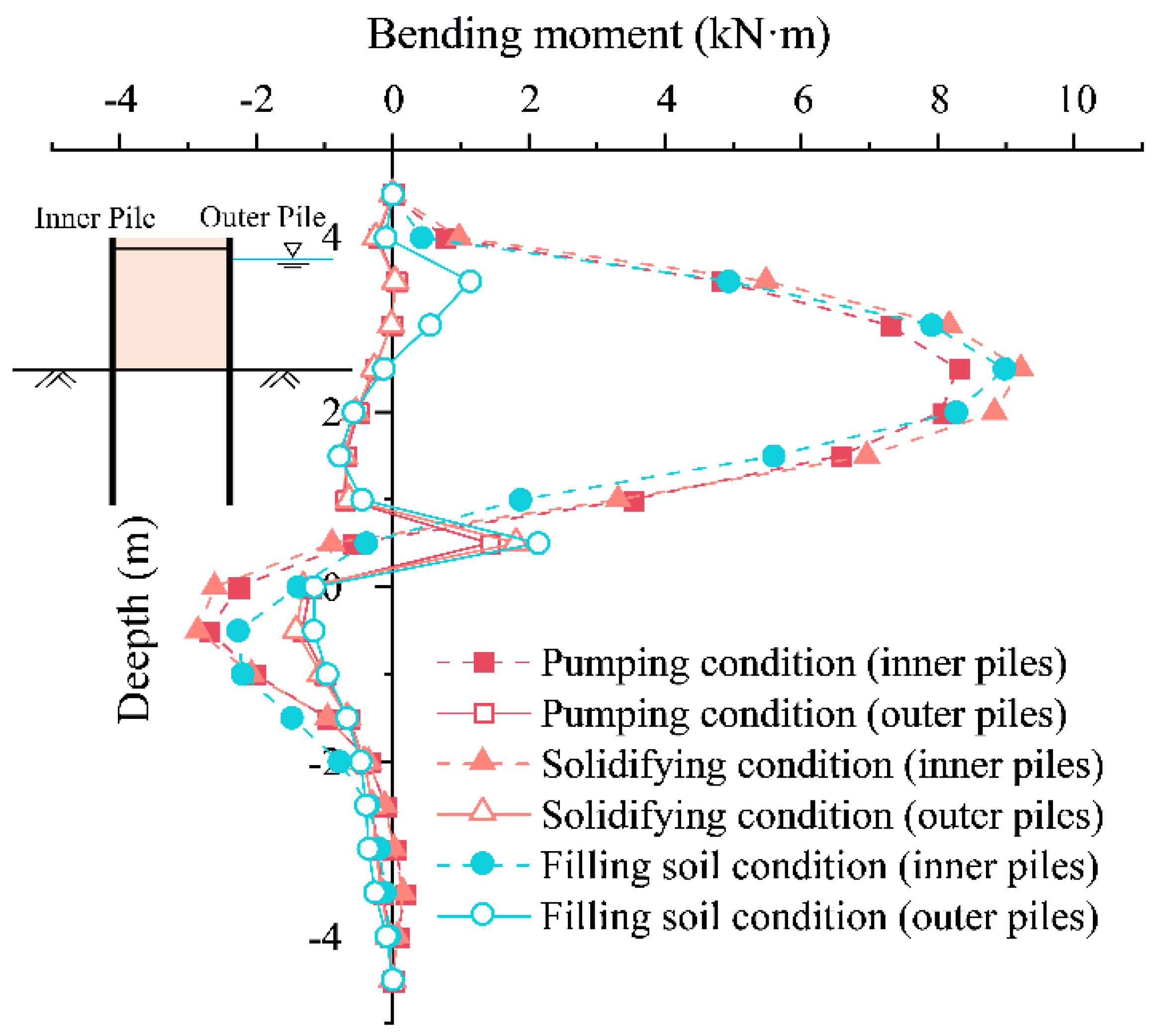
It can be observed from the above analysis that the most unfavorable working condition of the cofferdam is at stage 4, the grouting and solidifying step. To shorten the article length and focus on the key points, the deformation and stress of the cofferdam at stage 4 will be pointedly discussed. Figure 10 and Figure 11 respectively present the variation of horizontal displacement and bending moment at different heights of sheet piles, and all data were taken from the middle section of sheet piles. The displacement curve indicated that inner piles and outer piles performed relatively consistently about the horizontal deformation. It is worth noting that the heights of the two maximum displacements are different. In addition, the bottom of the inner piles was close to 10 mm, while the bottom displacement of the outer piles was close to 0. As for the bending moment, the inner piles bore a large bending moment of about 9 kN·m, while the outer piles hardly bore the bending moment. The bending moment reversal point was located 0.5 m above the riverbed for inner piles. The tension bars’ maximum axial stress value (136 MPa) occurred at stage 4.
According to the bending strength of the wood pile calculated by Qiu et al. [20], the maximum allowable bending moment value of the wood pile is 42 kN·m. The 10 mm diameter tension bar fracture stress value applied in the construction is 1570 MPa, much greater than the axial stress generated by the construction. Consequently, the deformation and stress of the cofferdam structure in the original construction scheme met the corresponding control requirements. However, this is just the analysis result under normal circumstances. If the inevitable defects of the cofferdam itself are considered, it is doubtful whether the cofferdam can meet the design requirements. To improve the overall safety factor of the cofferdam, the following analysis aims to examine the specific parameters of the cofferdam structure on the influence of deformation and stress.
5. Parametric Analysis
5.1. Parameters Value
From the above analysis, the sheet pile’s maximum horizontal deformation of 59 mm in the original construction plan slightly exceeds the control threshold of 0.6% for the pile length. It is necessary to analyze the cofferdam structure’s design parameters. Considering the particularity of this wood pile cofferdam, as well, according to the previous research results, the following four parameters are selected as the influencing factors to analyze their influence on the deformation and stress of the cofferdam: length of the wood pile, width of the dam, the horizontal interval of the tension bars and spacing of wood piles. As listed in Table 3, to accurately explore the four factors’ influence on the cofferdam’s structural stability, 17 different cofferdam structural forms were established, and the various influencing factors would be analyzed separately.
It should be pointed out that during the construction of the cofferdam, since the grouting and solidification after pumping is the most unfavorable working condition, and the inner piles bear more external forces, the following numerical analysis shows the deformation and stress of the inner piles at stage 4 (grouting and solidification step) only.
5.2. The Effect of Pile Length
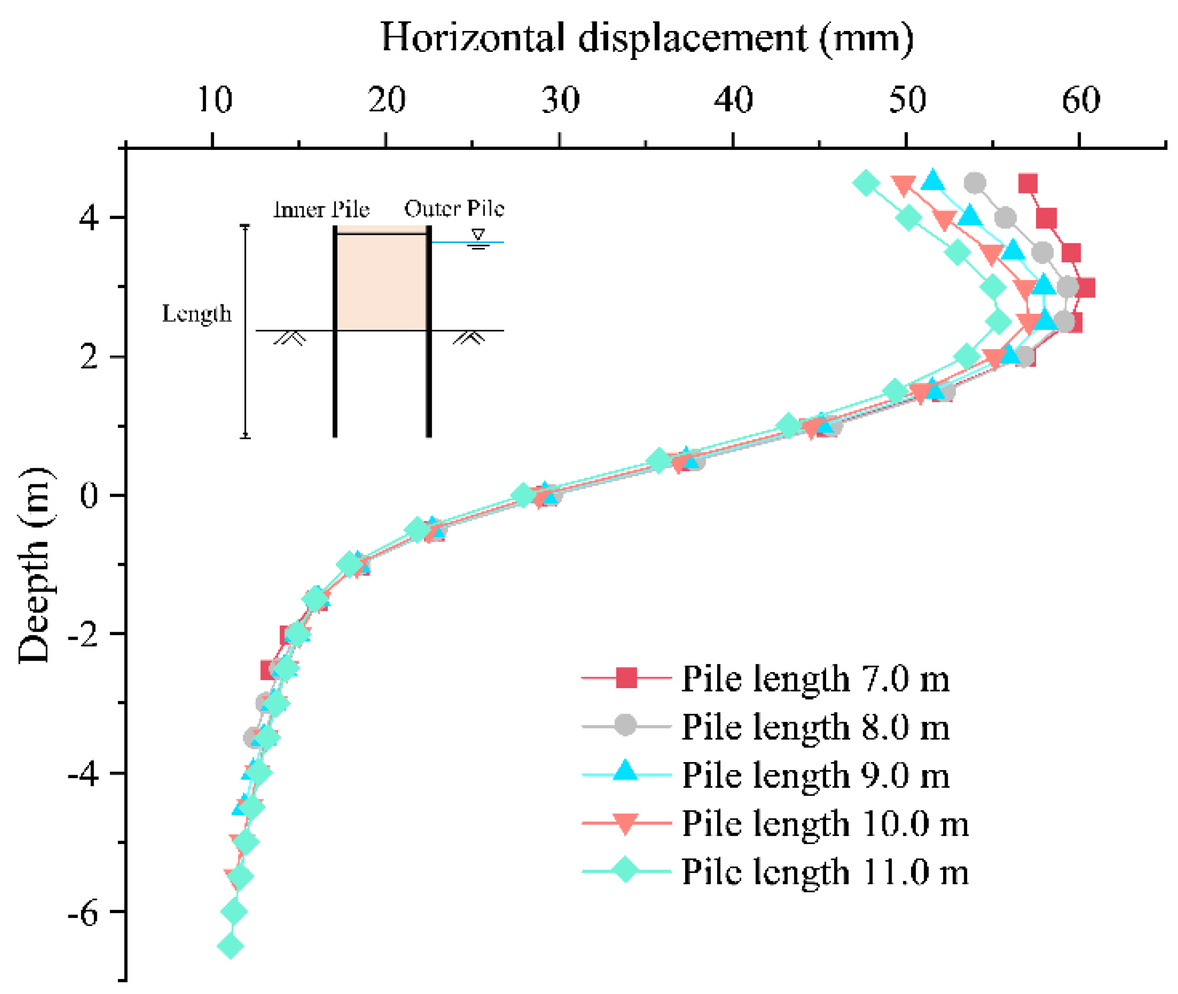
In general, the length of the pile influences the deformation and stress of the cofferdam structure. Figure 12 shows the deformation of the sheet pile under different pile lengths. In those simulation conditions, the cantilever part length of the pile was kept unchanged, and the embedded depth, which is the length of the part of piles driven below the riverbed, was changed only. When the pile length increased from 7.0 m to 11.0 m, the maximum horizontal displacement of the pile decreased by about 5 mm only, and the displacement of the pile top was reduced by about 10 mm. As the depth increased, this trend of decreasing displacement gradually passed off and finally manifested as a consistent displacement value of 11 mm at the bottom of the pile.
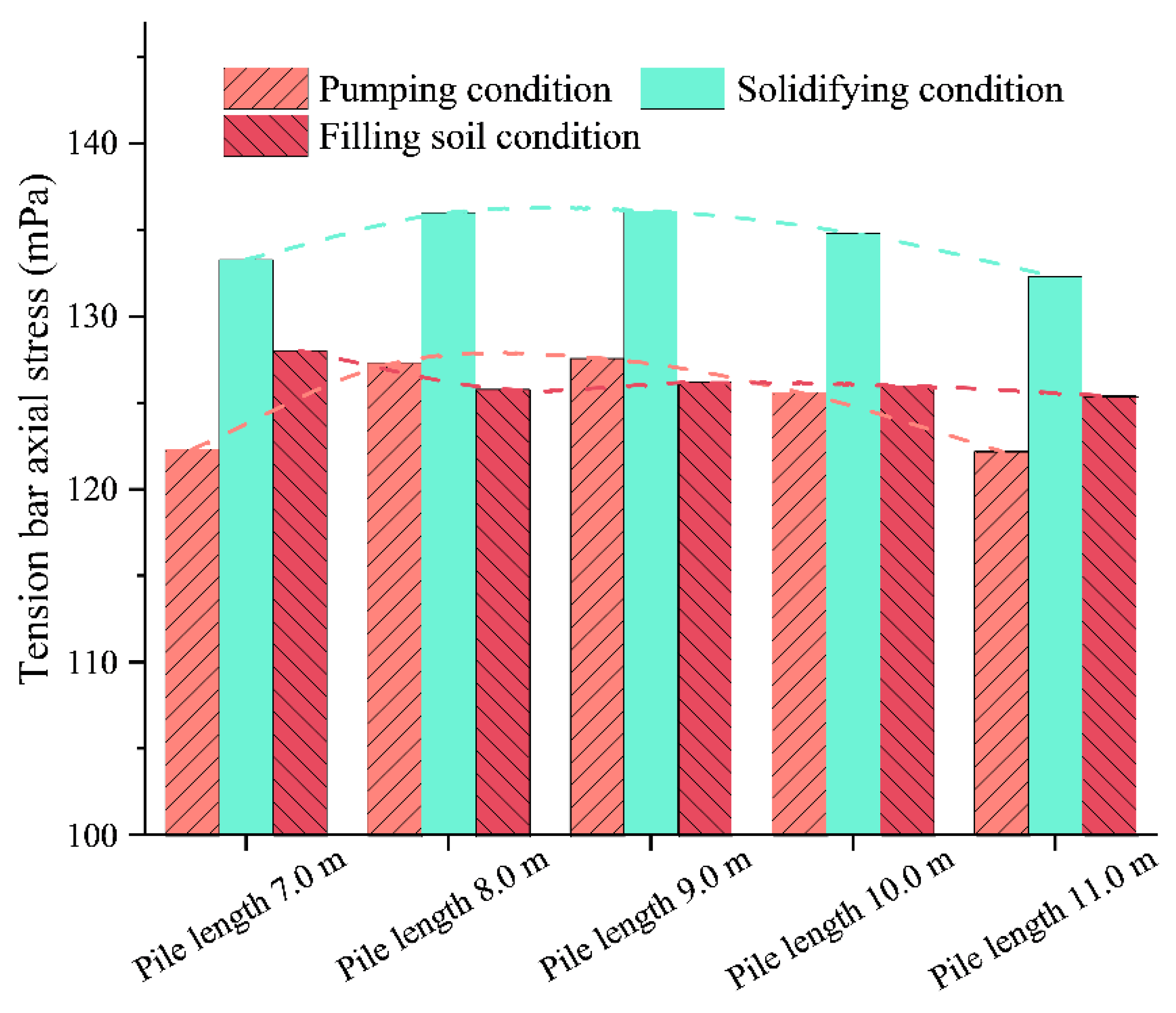
Compared with the change of the horizontal displacement under different pile lengths, the change in the pile’s bending moment was less significant. As shown in Figure 13, increasing the pile length played a small role in reducing the bending moment of the pile. In the case of different pile lengths, the changing trend of the bending moment of the pile body was almost the same, and the maximum value of the bending moment was located 2.0 m away from the pile top. In addition, the data presented in Figure 14 indicated no clear correlation between the axial force of tension bars and the length of piles.
5.3. The Effect of Dam Width
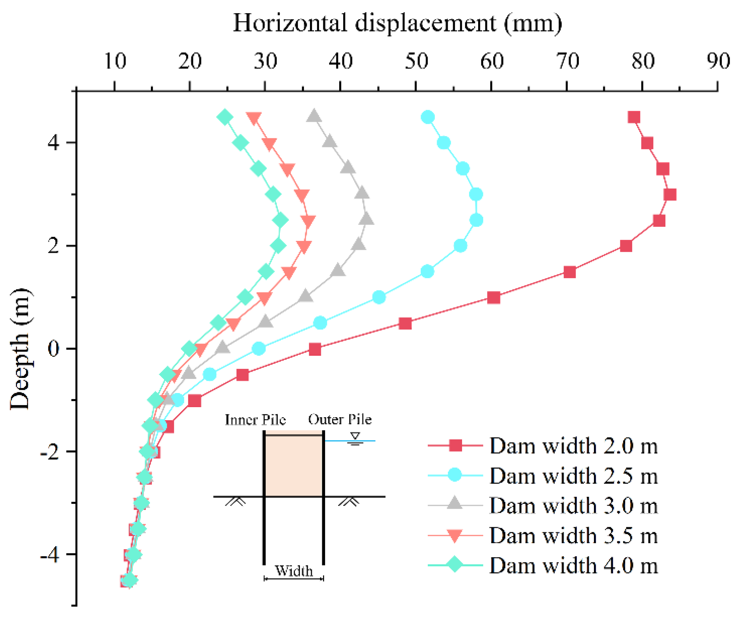
To explore the influence of the dam width on the cofferdam structure, the dam width was changed from 2.0 m to 4.0 m, there were intervals of 0.5 m, and other factors were kept unchanged. Figure 15 shows the horizontal pile deformation for different dam width conditions at stage 4, the grouting and solidifying step. Irrespective of the pile body of any part, it was evident that the horizontal displacement of the pile was closely related to the width of the dam, presenting an inverse correlation. When the dam width was 2.0 m, the maximum horizontal displacement of the pile was 83 mm, close to 1% of the pile length. However, when the dam width increases to 2.5 m, the maximum displacement of the pile shows a sharp decrease value of 55 mm. Therefore, increasing dam width can significantly reduce pile deformation. In general, the larger the width of the dam, the smaller the horizontal displacement of the pile, and the decreasing trend weakened with the increase of the dam body width.
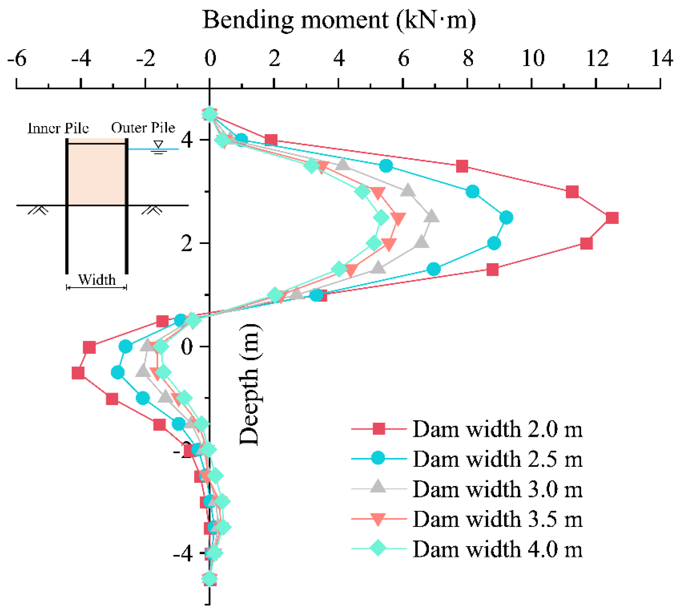
Similarly, Figure 16 shows the variation of pile bending moment with depth for different dam widths. Compared with the deformation of piles, the dam width also significantly affects the pile’s bending moment. When the dam width increased from 2.0 m to 4.0 m, the maximum bending moment value of the pile decreased from 12.5 kN·m to 5.3 kN·m, almost half of the bending moment for the 2.0 m width condition. Besides, no matter how the width of the dam changed, the bending moment reversal point of the inner piles was always located 0.5 m above the riverbed.
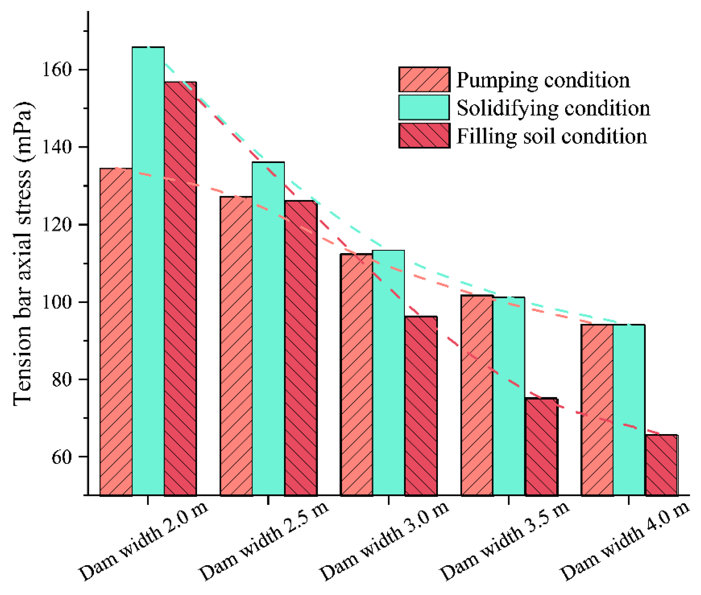
As shown in Figure 17, increasing the width of the dam can significantly reduce the axial stress of tension bars. It also can be found that filling soil could significantly lower tension bars’ axial force, especially in the case of a wide dam. To sum up, increasing the width of the dam body can effectively bring the deformation and stress of the cofferdam structure down. However, the cofferdam’s safety coefficient has sometimes reached the requirements. To prevent excessive deformation of the cofferdam, based on the analysis of the above data, it is recommended that the width of the cofferdam should not be less than 2.5 m.
5.4. The Effect of Tension Bars Interval
For steel sheet-pile cofferdams, the design parameters of tension bars, including the number, layers, and relative height, greatly influence the cofferdam structure. Therefore accurate calculation and analysis of tension bars are undoubtedly necessary. Similar to tension bars in steel sheet-pile cofferdams, the tension bars in the double-row wood-piled cofferdams are composed of small-diameter steel bars, which are tied to the wood purlins on both sides to achieve a pulling effect. Due to the particularity of the pile-membrane composite cofferdam structure, the height of tension bars could only be set at the top of piles. Therefore, unlike the double-row steel sheet-pile cofferdam, just the horizontal spacing of tension bars on the structural stability of the wood-piled cofferdam was considered in the following numerical analysis.
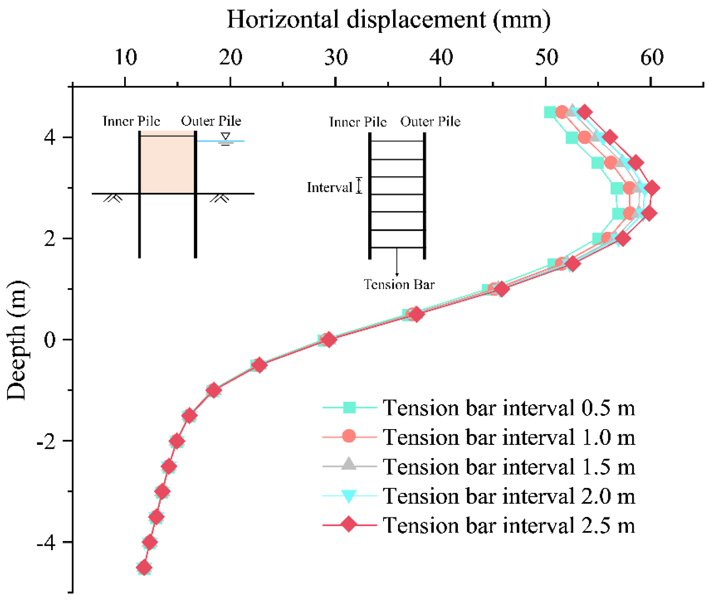
In specific conditions, all tension bars were unified to a diameter of 10 mm, but the spacing of tension bars was different: 0.5 m, 1.0 m, 1.5 m, 2.0 m, and 2.5 m. Correspondingly, the number of tension bars per unit length of piles in the model was different. Figure 18 reflects the deformation of the pile body under different tension bar intervals. The results indicated that the density of the tension bar setting had a certain influence on the pile deformation, slightly decreasing with the reduction of the tension bar interval.
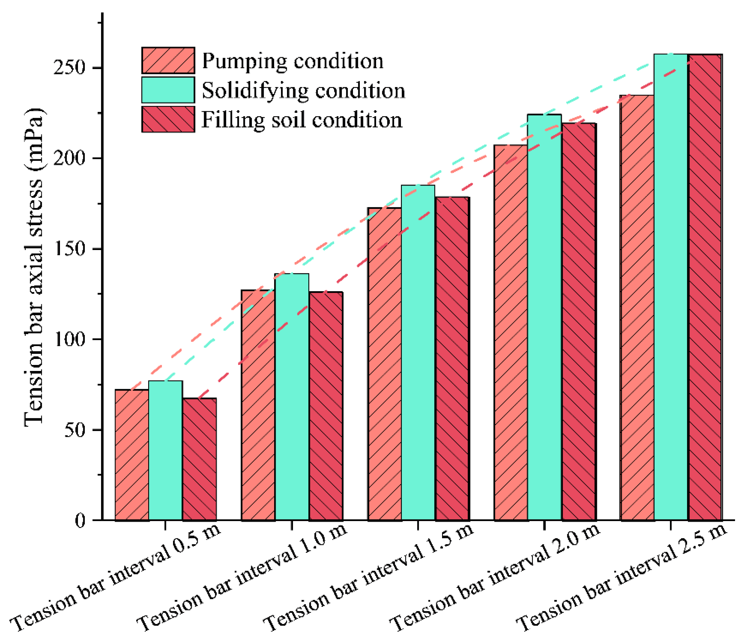
As shown in Figure 19, the changes in tension bar intervals had little effect on the bending moment for the bending moment of piles. Unexpectedly, the results indicated that reducing the interval of tension bars didn’t matter in decreasing the bending moment of the pile. According to the columnar data in Figure 20, the tension bar horizontal spacing variation significantly affected its axial stress. With the tie rods’ horizontal spacing expansion, the tension bars’ axial force rises in a straight line. It is apparent that, as the interval between tension bars increased, quantities of tension bars per unit length decreased, resulting in a sharp increase in the tensile force of each tension bar.
5.5. The Effect of Wood Piles Interval
Pile interval is an important parameter in cofferdam engineering, not only directly related to the cost of cofferdam construction but also closely related to the deformation and stress of the cofferdam structure. Based on previous engineering cases and experience in the original construction scheme, the interval between two adjacent wood piles was 0.5 m, equivalent to three wood piles per meter. This scheme was an empirical choice rather than a scientific judgment. Considering that the double-row wood piles were equivalent to sheet piles (liner element) with the same bending stiffness in this model, the sheet pile thickness under different pile intervals was calculated according to Equation (5). Therefore, the effect of pile interval could be reflected in the numerical model through sheet pile thickness conversion.
Five conditions of pile interval were selected as the object of parametric analysis, which were 0.3 m, 0.5 m, 0.7 m, 1.0 m, and 1.2 m. The corresponding thicknesses of the liner elements in the model were 146 mm, 124 mm, 110 mm, 100 mm, and 92 mm, respectively. In addition, the ‘pile interval’ mentioned in this section refers to the distance between the axial centers of two adjacent piles in the extension direction of piles.
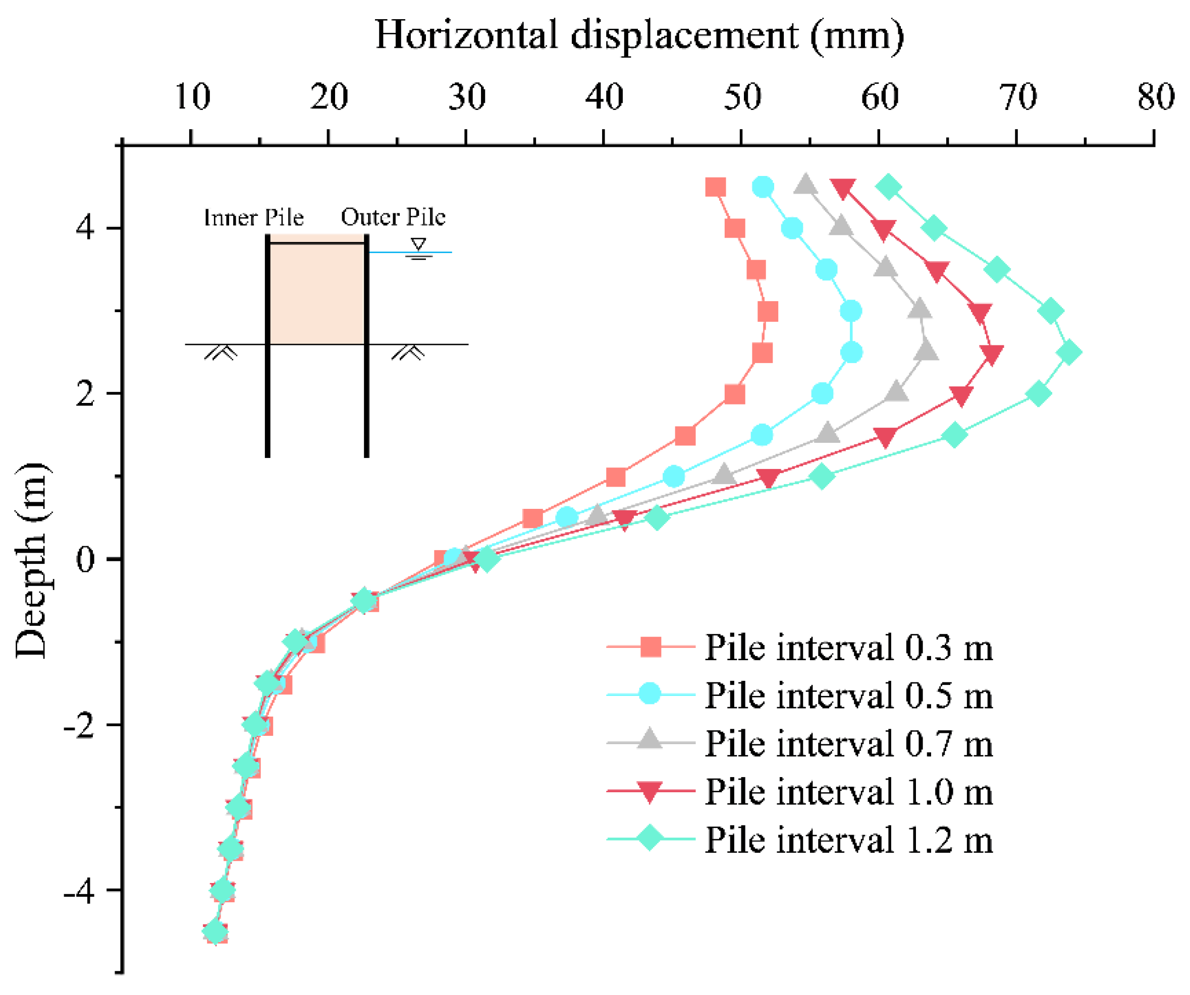
Figure 21 reflects the pile body deformation with depth under different conditions of pile interval. It can be observed from the curve in the figure, which approximately shows the characteristic of increasing proportionally. Along with the increase in the interval between piles, the horizontal deformation of piles above the riverbed increased. By contrast, the deformation of the piles below the riverbed tended to be almost consistent, expressing little difference among the above five conditions. The increase in the pile spacing led to the lower wood piles per unit length, and the overall resistance to deformation was weakened.
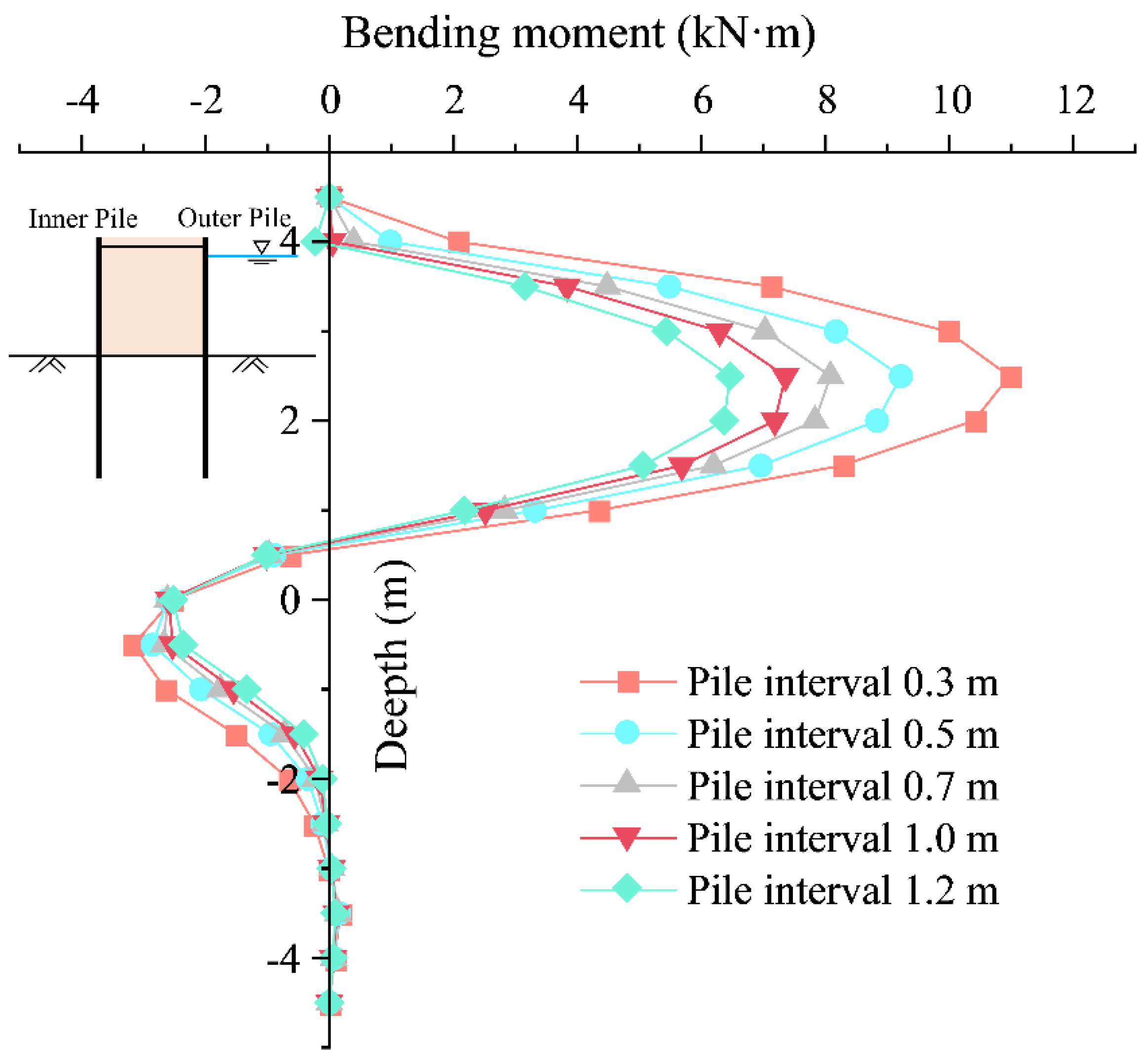
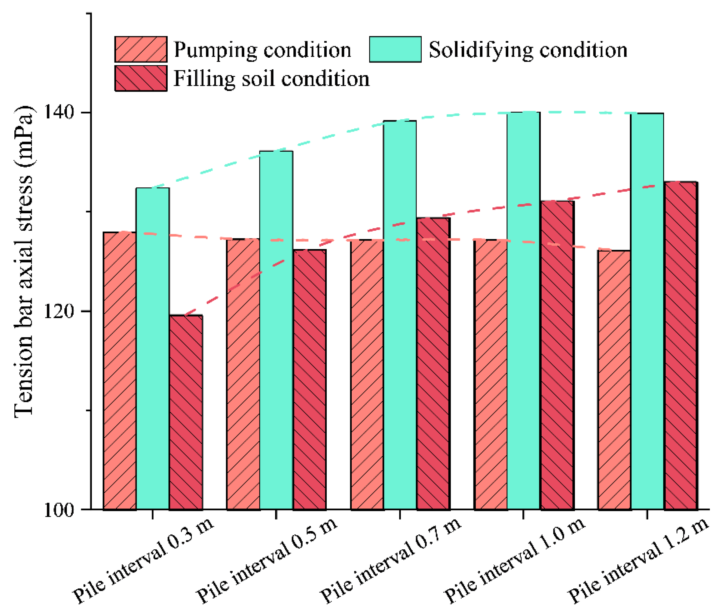
As shown in Figure 22, the bending moment of the pile body was brought down with the increase of the pile spacing. The maximum positive bending moment was still located 2.5 m above the riverbed. When the pile interval increased from 0.3 m to 1.2 m, the maximum positive bending moment of the pile declined from 11 kN·m to 6.5 kN·m. The increase in pile interval was equivalent to the reduction of sheet pile thickness in the model, resulting in smaller stress and a larger bending moment of piles. Figure 23 reflects the change in the axial stress of tension bars under different pile interval conditions. The axial force rose along with the increase of the pile spacing. However, the increasing trend was not linear—the larger the pile spacing, the slower the increase of the axial stress of tension bars.
5.6. Discussion
In the above numerical simulation, analysis for the four factors of pile length, dam width, tension bar interval, and pile spacing has been carried out. Certain parameters’ effect on deformation and structure stress is inconsistent and tends to be the opposite. Based on abundant analysis of parameters, as a way of dealing with different objective construction environments, a relatively balanced parameter combination can be established between the internal force of the structure and the deformation of the pile body.
Some basic laws can be summarized from the above experimental data. Increasing the pile length can reduce the deformation of piles by a small margin but does not play a significant role in internal force control. Since the dam soil and the double-row wood piles form an integral resistance to external force, the dam width is a key factor affecting the stability of the cofferdam structure, regardless of deformation or stress, which is also the significant difference between the double-row wood-piled cofferdams and other single-row piles cofferdams. To a certain extent, enlarging the interval between tension bars is equivalent to reducing the number of tension bars on a certain length of the dam, resulting in a larger axial force shared by each tension bar. Compared with the steel sheet-pile cofferdam, bringing down the interval of tension bars does not play a significant role in reducing the pile deformation and bending moment. Reducing the spacing between the wood piles enables a great decrease in the deformation of piles but has an adverse effect on the bending moments of piles. As indicated by the above 17 simulated conditions, the axial stress of the tension bars does not reach its fracture stress limit for far. Consequently, the axial force of tension bars is not the key parameter restricting the stability of the wood pile cofferdam.
6. Steel Pipe Pile Reinforcement Effect
6.1. Description of Steel Pipe Pile Reinforcement
Due to convenient construction and the low cost of double-row wood-piled structures, the first choice under shallow water silt geological conditions, it has been widely used in some cofferdam projects. However, the wood-piled cofferdam may be unreliable for projects with high requirements for cofferdam deformation or when the water depth exceeds a certain range. To further improve the stability of the wood-piled cofferdam in unfavorable environments and enhance the ability of the cofferdam to resist deformation and bending moment, it is certainly a practical solution to add steel pipe piles inside the cofferdam.
As shown in Figure 24, based on the original double-row wood-piled cofferdam scheme, a row of steel pipe piles will be built along the inner wood piles. To make the wood pile and the steel pipe pile more closely combined and form a whole to resist deformation, the steel pipe pile is close to the steel purlin, tied to the inner wood piles. Specifically, the length of steel pipe piles is 18 m, the outer diameter is 420 mm, the thickness is 10 mm, and the interval between two adjacent steel pipe piles is 2.0 m. In the following numerical simulation, the selection of various parameters of sheet piles is determined according to the formula of equivalent bending stiffness in Section 2.3.
6.2. Analysis of Reinforcement Effect
It can be observed from the above analysis that in the cofferdam numerical model, the inner row of the cofferdam reinforced with steel pipe piles differed from that of the original double-row wood-piled cofferdam. The major performance is the difference in inner pile length and elastic modulus. Specifically, the parameters of the upper half of the reinforced inner piles are pointed out, with the thickness of 241 mm, the elastic modulus of 1.03 × 10⁵ MPa, as well the parameters of the lower half: the thickness of 118 mm, and the elastic modulus of 2 × 10⁵ MPa.
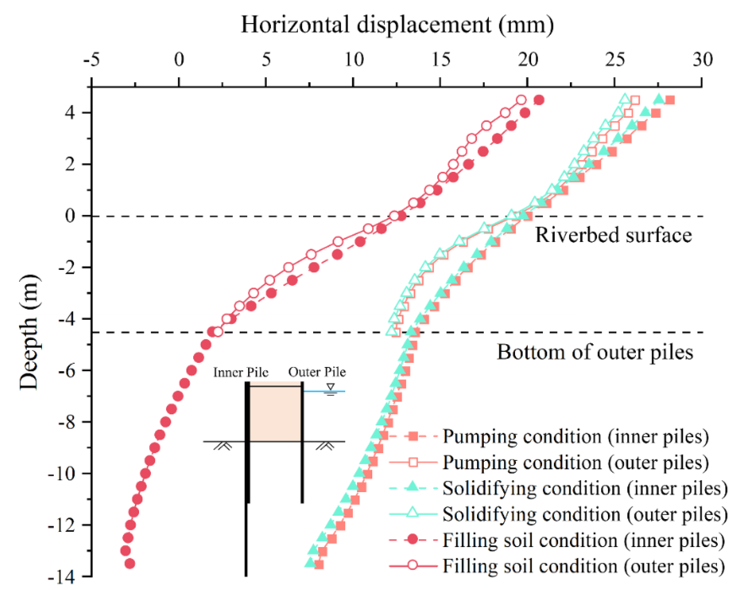
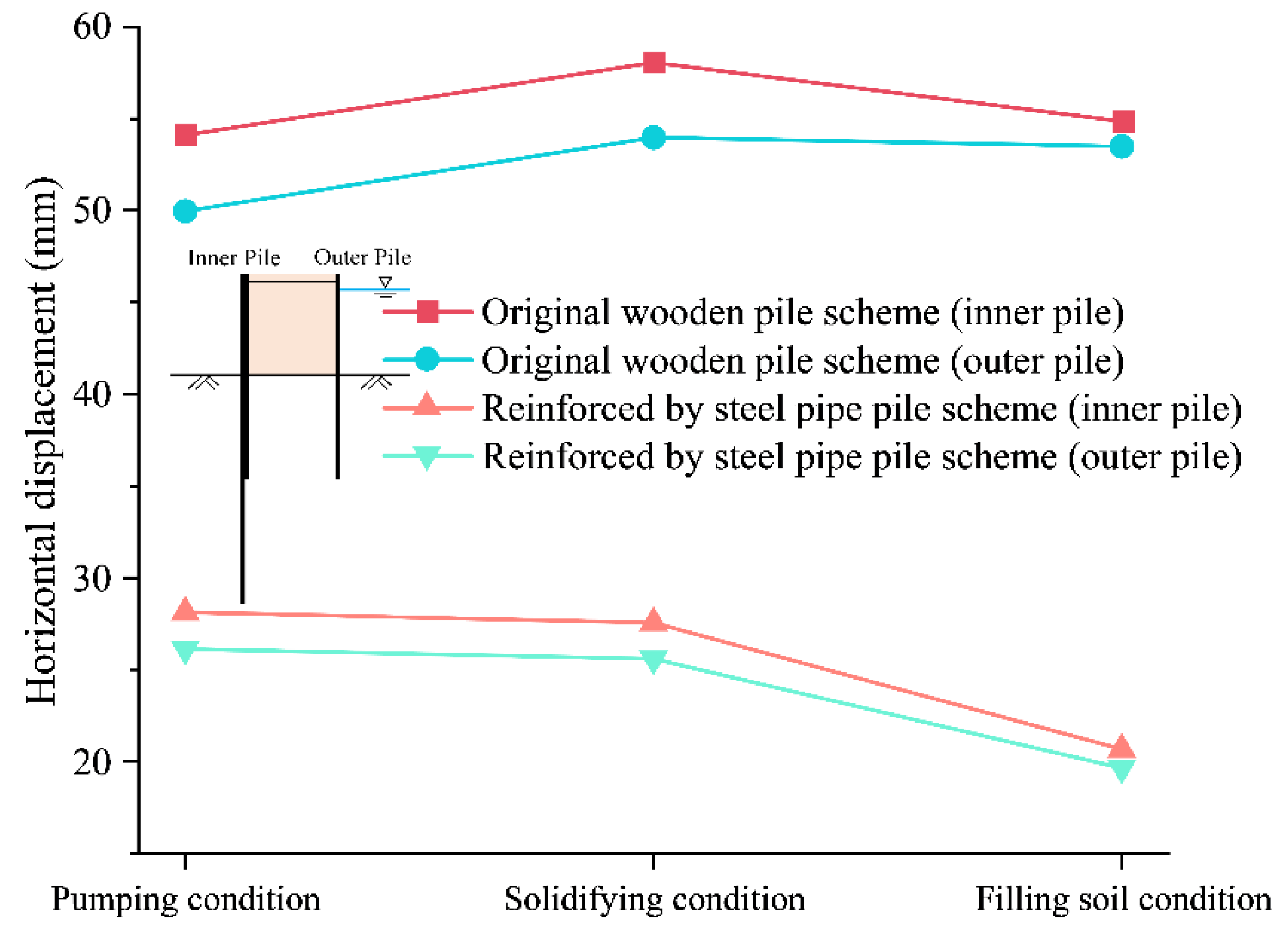
Figure 25 is the horizontal displacement curve of the reinforced pile. Due to the barrier effect of dam filling, the deformation of the inner and outer piles is relatively consistent at different depths; also, the deformation of the outer piles is slightly smaller than that of the inner piles. Unlike the wood-piled cofferdam, the maximum horizontal displacement of the reinforced cofferdam occurs at the top of piles. To visually compare the reinforcement effect of the steel pipe piles, the horizontal displacement curves of the piles under the two cofferdam schemes are plotted in Figure 26. Since the cofferdam has been reinforced with steel pipe piles, the deformation of the pile body is significantly reduced, especially in the final soil filling stage. The most critical thing to be observed is that the maximum horizontal deformation of the piles under the two schemes is respectively 58 mm and 28 mm, which confirms that the reinforcement effect of the steel pipe pile is significant.
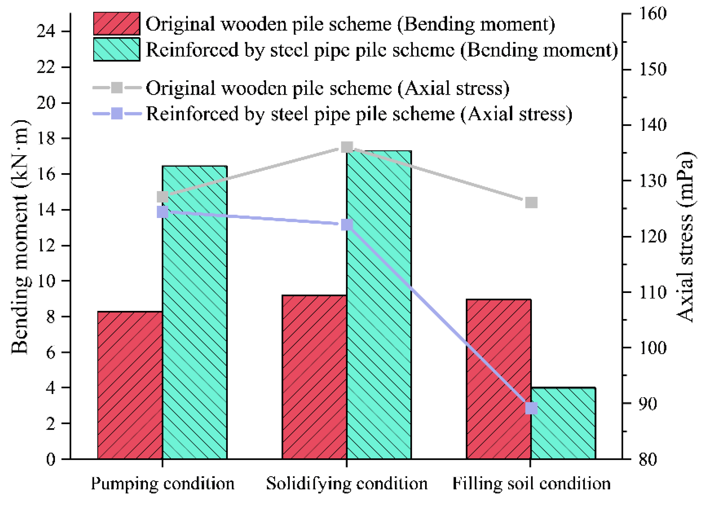
Figure 27 compares the internal structural forces of the reinforced and unreinforced solutions cofferdams. For the maximum bending moment of piles, the inner piles with larger force are selected for comparison. In the original wood pile cofferdam scheme, the bending moment of the piles does not change much, and the value under the three main construction stages is around 9 kN·m within safe limits. The added steel pipe piles for the tension bars share part of the tensile force. Compared with the original wood-piled cofferdam scheme, the axial stress of tension bars decreases sharply in the steel pipe pile reinforcement scheme.
It should also be noted that the upper half of the lining unit is reinforced by steel pipe piles in the model. It is given parameters by simulating the combination of two structures with one structural element. Therefore, the deformation and stress of the two structures are regarded as consistent, which may lead to some deviations between the calculated and actual results.
7. Conclusions
Based on the principle of stiffness equivalence, the deformation and stress of the double-row wood-piled cofferdam were investigated by presenting an island-type cofferdam case in Shaoxing, China. In the field construction, the cofferdam functioned well without large deformation and leakage, confirming the double-row pile cofferdam scheme’s reliability. The primary conclusions drawn from this study can be summarized in the following points:
- According to the analysis of the double-row wood-piled cofferdam scheme, the maximum horizontal deformation of the pile can be controlled at about 0.6% of pile length, either the peak values of the bending moment and tension bar stress in the construction process are both within the allowable range and still have large redundancy. In general, the original scheme of the wood-piled island cofferdam can meet the basic construction safety requirements.
- The width of the dam is an important parameter affecting the stability of the cofferdam and should be the primary consideration in the design. Other parameters, such as the pile length, the pile interval, and the tension bars interval, ought to be determined by the dam interval. Summarizing a large number of parameter sensitivity analyses, it is concluded that the axial force of tension bars in the wood-piled cofferdam is not large, and the wood piles bear most of the external force. In the design of the cofferdam structure, more attention should be paid to the deformation and bending moment of the wood piles.
- The steel pipe pile reinforcement scheme performed better than the double-row wood-piled cofferdam scheme. The deformation of the pile after reinforcement is brought down by more than half, but the reinforcement is useless in reducing the bending moment of wood piles. The scheme reinforced by steel pipe piles provides a new idea for island-type cofferdams with rigorous structural deformation control.
However, the wood piles are independently inserted in the riverbed and connected by the surrounding wood pile purlins. In this study, these independent wood piles were equivalent to continuous and homogeneous sheet pile material, which may deviate from the actual situation. Moreover, further verification of the proposed research by monitoring data in the field and centrifuge model test results is required. These issues will be addressed in future research work to extend the versatility and application of the proposed wood-piled island cofferdam by building sophisticated numerical models.
Author Contributions
Conceptualization, S.C. and Y.W.; methodology, Y.L. (Yonghai Li).; software, X.L.; validation, P.G.; formal analysis, W.H.; investigation, Y.L. (Yan Liu). All authors have read and agreed to the published version of the manuscript.
Funding
This research work was funded by the National Natural Science Foundation of China (42077249, 51774107), the Opening Project of State Key Laboratory of Explosion Science and Technology, Beijing Institute of Technology (KFJJ21-03Z).
Institutional Review Board Statement
Not applicable.
Informed Consent Statement
Not applicable.
Data Availability Statement
Some or all data, models, or code generated or used during the study are available from the corresponding author by request.
Conflicts of Interest
The authors declare no conflict of interest.
References
- Lefas, I.; Georgiannou, V. Analysis of a cofferdam support and design implications. Comput. Struct. 2001, 79, 2461–2469. [Google Scholar] [CrossRef]
- Xue, R.; Bie, S.; Guo, L.; Zhang, P. Stability Analysis for Cofferdams of Pile Wall Frame Structures. KSCE J. Civ. Eng. 2019, 23, 4010–4021. [Google Scholar] [CrossRef]
- Chen, L.; Jeng, D.-S. Study on the seabed response around a dumbbell cofferdam under combined wave and current loading. Ocean Eng. 2022, 256, 111456. [Google Scholar] [CrossRef]
- Arboleda-Monsalve, L.G.; Uribe-Henao, A.F.; Velásquez-Pérez, A.; Zapata-Medina, D.G.; Sarabia, F. Performance of Urban Cofferdams Braced with Segmental Steel and Reinforced Concrete Ring Beams. J. Geotech. Geoenvironmental Eng. 2018, 144, 04018015. [Google Scholar] [CrossRef]
- Wang, J.; Xiang, H.; Yan, J. Numerical Simulation of Steel Sheet Pile Support Structures in Foundation Pit Excavation. Int. J. Géoméch. 2019, 19, 05019002. [Google Scholar] [CrossRef]
- Kang, A.; Zhu, B.; Lin, P.; Ju, J.; Zhang, D. Experimental and numerical study of wave-current interactions with a dumbbell-shaped bridge cofferdam. Ocean Eng. 2020, 210, 107433. [Google Scholar] [CrossRef]
- Ti, Z.; Wei, K.; Qin, S.; Mei, D.; Li, Y. Assessment of random wave pressure on the construction cofferdam for sea-crossing bridges under tropical cyclone. Ocean Eng. 2018, 160, 335–345. [Google Scholar] [CrossRef]
- Gui, M.-W.; Han, K.-K. An investigation on a failed double-wall cofferdam during construction. Eng. Fail. Anal. 2009, 16, 421–432. [Google Scholar] [CrossRef]
- Zeng, C.-F.; Xue, X.-L.; Zheng, G.; Xue, T.-Y.; Mei, G.-X. Responses of retaining wall and surrounding ground to pre-excavation dewatering in an alternated multi-aquifer-aquitard system. J. Hydrol. 2018, 559, 609–626. [Google Scholar] [CrossRef]
- Benmebarek, N.; Benmebarek, S.; Kastner, R. Numerical studies of seepage failure of sand within a cofferdam. Comput. Geotech. 2005, 32, 264–273. [Google Scholar] [CrossRef]
- Noh, J.; Lee, S.; Kim, J.-S.; Molinas, A. Numerical modeling of flow and scouring around a cofferdam. J. Hydro-environment Res. 2012, 6, 299–309. [Google Scholar] [CrossRef]
- Veiskarami, M.; Zanj, A. Stability of sheet-pile walls subjected to seepage flow by slip lines and finite elements. Geotechnique 2014, 64, 759–775. [Google Scholar] [CrossRef]
- Madanayaka, T.A.; Sivakugan, N. Simple solutions for square and rectangular cofferdam seepage problems. Can. Geotech. J. 2019, 56, 730–745. [Google Scholar] [CrossRef]
- Wang, X.; Zhou, X.; Zhou, M.; Tian, Y. Behavior of Large Geotextile Mat Cofferdam with a New Arrangement of Geotextile Reinforcement Stiffness Lying on Soft Sediments. Int. J. Géoméch. 2020, 20, 04020121. [Google Scholar] [CrossRef]
- Jiang, P.; Huang, Y.; Tao, Z.; Zhu, J.; Wang, N.; Qiao, J. Deformation Characteristics and Safety Evaluation of the Throw Filling Soft Clay Cofferdam under Super-Historical Flood Conditions. Adv. Civ. Eng. 2022, 2022, 9578477. [Google Scholar] [CrossRef]
- Yu, H.; Cai, C.; Bobet, A.; Zhao, X.; Yuan, Y. Analytical solution for longitudinal bending stiffness of shield tunnels. Tunn. Undergr. Space Technol. 2019, 83, 27–34. [Google Scholar] [CrossRef]
- Liu, A.; Li, B.; Chen, J.; Gao, C. Research and application of large diameter steel cylinder island construction technology in Hong Kong-Zhuhai-Macao Bridge project. Ships Offshore Struct. 2021, 16, 33–41. [Google Scholar] [CrossRef]
- Guo, P.; Gong, X.; Wang, Y. Displacement and force analyses of braced structure of deep excavation considering unsymmetrical surcharge effect. Comput. Geotech. 2019, 113, 103102. [Google Scholar] [CrossRef]
- Guo, P.; Lei, G.; Luo, L.; Gong, X.; Wang, Y.; Li, B.; Hu, X.; Hu, H. Soil Creep Effect on Time-Dependent Deformation of Deep Braced Excavation. Adv. Mater. Sci. Eng. 2022, 2022, 5655592. [Google Scholar] [CrossRef]
- Qiu, L.; Sheng, W.; Wang, S. Experimental Study on Material Mechanical Properties of Wood Pile. Eng. Test. 2013, 53, 24–26. (In Chinese) [Google Scholar]
Figure 1.
Equivalence of cofferdam structure.

Figure 2.
Equivalent of wood piles.

Figure 3.
Equivalent of steel pipe piles.

Figure 4.
Equivalent of a combination of steel pipe piles and wood piles.

Figure 5.
Plan view of the project.

Figure 6.
Double row wood pile structure.

Figure 7.
Construction steps.

Figure 8.
Mesh of the numerical model.

Figure 9.
Horizontal displacement contours of piles at different stages (unit: m).

Figure 10.
Horizontal displacement curve of piles at different stages.

Figure 11.
Bending moment of piles at different stages.

Figure 12.
Pile horizontal displacement of different pile length conditions.

Figure 13.
Pile bending moment of different pile length conditions.

Figure 14.
Tension bar axial stress of different pile length conditions.

Figure 15.
Pile horizontal displacement of different dam width conditions.

Figure 16.
Pile bending moment of different dam width conditions.

Figure 17.
Tension bar axial stress of different dam width conditions.

Figure 18.
Pile horizontal displacement of different tension bar interval conditions.

Figure 19.
Pile bending moment of different tension bar interval conditions.

Figure 20.
Tension bar axial stress of its different interval conditions.

Figure 21.
Pile horizontal displacement of wood pile interval conditions.

Figure 22.
Pile bending moment of wood pile interval conditions.

Figure 23.
Tension bar axial stress of wood pile interval conditions.

Figure 24.
Steel pipe pile reinforced cofferdam structure.

Figure 25.
Horizontal displacement of reinforced piles.

Figure 26.
Comparison of the horizontal displacement between reinforced piles and double-row wood piles.
Figure 26.
Comparison of the horizontal displacement between reinforced piles and double-row wood piles.

Figure 27.
Comparison of the internal force between reinforced piles and double-row wood piles.


Table 1.
Properties of the materials modeled in numerical analysis.
| Material | Silt | Clay | Solidifies Soil | Backfill Soil | Wood Pile | Tension Bar |
|---|---|---|---|---|---|---|
| Model | Mohr- Coulomb | Mohr- Coulomb | Mohr- Coulomb | Mohr- Coulomb | Elastic | Elastic |
| Element | Brick | Brick | Brick | Brick | Liner | Cable |
| Thickness/m | 20.0 | 5.0 | 2.0 | 4.5 | - | - |
| Density/kg·m−3 | 1700 | 1900 | 1800 | 1800 | 800 | 7800 |
| Young’s modulus/MPa | 2.4 | 6.6 | 5.2 | 4.6 | 6.0 × 10³ | 2.0 × 10⁵ |
| Friction angle/° | 10 | 15 | 12 | 10 | - | - |
| Cohesion/kPa | 1.4 × 10⁴ | 5.6 × 10⁴ | 1.5 × 10⁴ | 1.0 × 10⁴ | - | - |
| Poisson’s ratio | 0.35 | 0.3 | 0.3 | 0.3 | 0.3 | 0.2 |
| Permeability coefficient/m·s−1 | 10−6 | 10−8 | 10−7 | - | - | - |
Table 2.
Stages of construction in finite difference analysis.
| Stage No. | Description | Model Operation |
|---|---|---|
| 1 | Initializing stress field and seepage field balance | Activating the soil layer (silt and clay), setting seepage boundary |
| 2 | Dam construction | Activating the cofferdam structure (liner and cable elements) |
| 3 | Dewatering inside the cofferdam | Lowering the cofferdam water level from 4.0 m to the riverbed |
| 4 | Grouting to reinforce silty foundations | Modifying the silt (2.0 m below the riverbed) parameter to solidified soil |
| 5 | Backfilling | Activating the backfilling soil |
Table 3.
17 cofferdam structural forms of different parameters.
| Number of Cases | Length of Piles/m | Width of the Dam Body/m | Interval of Adjacent Tension Bars/m | Interval of Adjacent Wood Piles/m |
|---|---|---|---|---|
| 1 | 7.0 m | 2.5 m | 1.0 m | 0.5 m |
| 2 | 8.0 m | 2.5 m | 1.0 m | 0.5 m |
| 3 | 9.0 m | 2.5 m | 1.0 m | 0.5 m |
| 4 | 10.0 m | 2.5 m | 1.0 m | 0.5 m |
| 5 | 11.0 m | 2.5 m | 1.0 m | 0.5 m |
| 6 | 9.0 m | 2.0 m | 1.0 m | 0.5 m |
| 7 | 9.0 m | 3.0 m | 1.0 m | 0.5 m |
| 8 | 9.0 m | 3.5 m | 1.0 m | 0.5 m |
| 9 | 9.0 m | 4.0 m | 1.0 m | 0.5 m |
| 10 | 9.0 m | 2.5 m | 0.5 m | 0.5 m |
| 11 | 9.0 m | 2.5 m | 1.5 m | 0.5 m |
| 12 | 9.0 m | 2.5 m | 2.0 m | 0.5 m |
| 13 | 9.0 m | 2.5 m | 2.5 m | 0.5 m |
| 14 | 9.0 m | 2.5 m | 1.0 m | 0.3 m |
| 15 | 9.0 m | 2.5 m | 1.0 m | 0.7 m |
| 16 | 9.0 m | 2.5 m | 1.0 m | 1.0 m |
| 17 | 9.0 m | 2.5 m | 1.0 m | 1.2 m |
Publisher’s Note: MDPI stays neutral with regard to jurisdictional claims in published maps and institutional affiliations. |
© 2022 by the authors. Licensee MDPI, Basel, Switzerland. This article is an open access article distributed under the terms and conditions of the Creative Commons Attribution (CC BY) license (https://creativecommons.org/licenses/by/4.0/).
Share and Cite
MDPI and ACS Style
Chen, S.; Wang, Y.; Li, Y.; Li, X.; Guo, P.; Hou, W.; Liu, Y. Deformation and Force Analysis of Wood-Piled Island Cofferdam Based on Equivalent Bending Stiffness Principle. Buildings 2022, 12, 1104. https://doi.org/10.3390/buildings12081104
AMA Style
Chen S, Wang Y, Li Y, Li X, Guo P, Hou W, Liu Y. Deformation and Force Analysis of Wood-Piled Island Cofferdam Based on Equivalent Bending Stiffness Principle. Buildings. 2022; 12(8):1104. https://doi.org/10.3390/buildings12081104
Chicago/Turabian StyleChen, Shi, Yixian Wang, Yonghai Li, Xian Li, Panpan Guo, Weichao Hou, and Yan Liu. 2022. "Deformation and Force Analysis of Wood-Piled Island Cofferdam Based on Equivalent Bending Stiffness Principle" Buildings 12, no. 8: 1104. https://doi.org/10.3390/buildings12081104
Note that from the first issue of 2016, this journal uses article numbers instead of page numbers. See further details here.