
Influence of Morphology Characteristics on Shear Mechanical Properties of Sawtooth Joints


1
Hunan Provincial Communications Planning, Survey and Design Institute, Changsha 410200, China
2
School of Resources and Safety Engineering, Central South University, Changsha 410083, China
*
Authors to whom correspondence should be addressed.
Buildings 2022, 12(7), 886; https://doi.org/10.3390/buildings12070886
Submission received: 24 May 2022
/
Revised: 17 June 2022
/
Accepted: 20 June 2022
/
Published: 22 June 2022
(This article belongs to the Topic New Trends in Rock Materials Mechanics and Engineering Geology)
Abstract
:The interface problem exists widely in building. Joints are interfaces of rock mass structures. To further study the influence of morphological characteristics on the shear mechanical properties of sawtooth joints, this paper prepared rock-like materials based on the similarity principle and carried out direct shear tests of sawtooth joints. The results showed that: (1) the peak shear displacement of joints first increases and then decreases with increasing normal stress, but the normal trend of stress during turning is different under different sawtooth angles. When the sawtooth angle of the joints is small, the decrease in shear stress between shear strength and residual shear strength is not obvious, and the rate of decrease is also small. (2) The shear strength of joints is positively correlated with normal stress. Using the Mohr–Coulomb criterion to analyze the shear strength of joints, it was found that the cohesion c and internal friction angle α of joints increased nonlinearly with increasing sawtooth angle, but their increasing trends were different. By introducing the function relation between cohesion, internal friction angle, and sawtooth angle into the classical shear strength equation, an empirical equation for the shear strength of joints was established in consideration of sawtooth angle. (3) There are two modes of shear failure for serrated joints: the “saw-toothed sliding gnawing failure mechanism” (SSG) and the “tensile fracture mechanism” (TFM). In the SSG, the shear failure mode of joints evolves in a slipping–gnawing–complete gnawing mechanism with increasing sawtooth angle and normal stress. The TFM mainly occurs at high sawtooth angles. This study provides a theoretical reference for the prediction and prevention of geological disasters.
1. Introduction
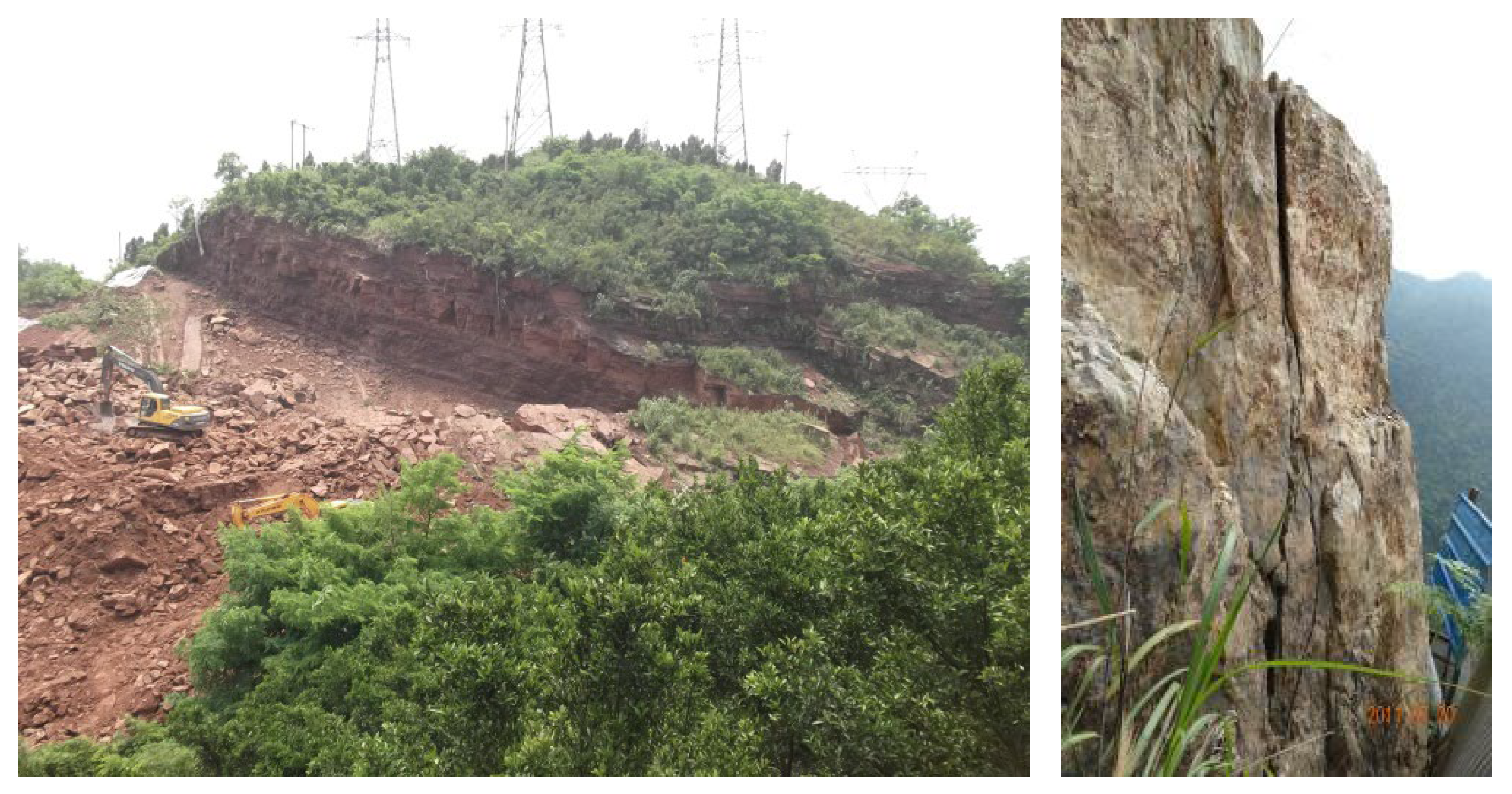
The interface problem exists widely in buildings. For example, in building foundations, the mechanical properties of the interface between the pile and the geotechnical materials often determine the mechanical properties of the pile foundation. In foundation pit support, there is the interface between the mortar and the geotechnical materials; in tunnel support, there is the interface between support lining and geotechnical materials. Therefore, it is necessary to study the mechanical properties of the interface. The existence of interfaces disrupts the continuity and integrity of the rock mass [1,2,3,4], and its mechanical behavior influences the stability of the rock mass. With the rapid development of urbanization, the scale of buildings near hillsides and tunnels has expanded continuously, leading to a significant increase in the degree of threat to building safety from geological hazards [5,6,7]. A joint is an interface of rock mass structures. Geological disasters such as slope landslides (Figure 1), tunnel collapse, and debris flow are often caused by the instability of joints [8,9,10,11]. Therefore, it is necessary to study the influence of joints on the mechanical properties of rock masses.
Since rock mass failure usually manifests as shear slip along the joints, most studies on the mechanical properties of joints have been based on the analysis of shear mechanical behavior [12,13,14]. Among them, the study of the morphological characteristics of joints is a hotspot in the field [15,16,17,18]. By performing shear tests on a large number of natural rough joints, Barton and Choubey [19] first used roughness parameters to quantitatively describe the morphological characteristics of joints, and proposed the JRC-JCS model, which is widely used in engineering [20,21]. This model, although derived empirically, provides a firm basis for the estimation of shear strength, which is directly influenced by the normal stress and joint roughness. This model has subsequently been improved by many scholars [22,23]. Similarly, Xia, Tang [24] studied the relationship between shear dilatancy effect and the surface topography of the joint, and proposed a shear strength model taking into consideration the surface topography. Based on both in situ and laboratory direct shear tests on rock joints, Sanei, Faramarzi [25] studied the effect of the length of the joint on shear strength, and established an empirical equation that can relate joint shear strength at the laboratory scale to that at the field scale.
The above research has well described the shear mechanics mechanism of joints, but most of the analysis on the morphological characteristics has only focused on the quantitative description of the shear curve of joints and the research on the shear strength theory of irregular joints [26,27,28]. The influence of morphology on the shear mechanical behavior of the joint should also be considered [29,30,31]. According to the degree of fluctuation of joints, the joint can be classified into four categories: straight, stepped, serrated, and wavy. Among them, the serrated structural plane is the basic unit of structural plane patterns. Therefore, using similar materials in the laboratory, in this paper a direct shear test of sawtooth joints under different normal stresses was carried out. When analyzing the shear stress–shear displacement curve, shear strength, and the morphological characteristics after failure, the Mohr–Coulomb criterion is introduced to discuss the effect of the sawtooth angle on the shear properties of the joints, and the empirical formula of the shear strength of sawtooth joints is established, providing a theoretical reference for the forecast and prevention of geological disasters.
2. Specimen Preparation and Test Scheme
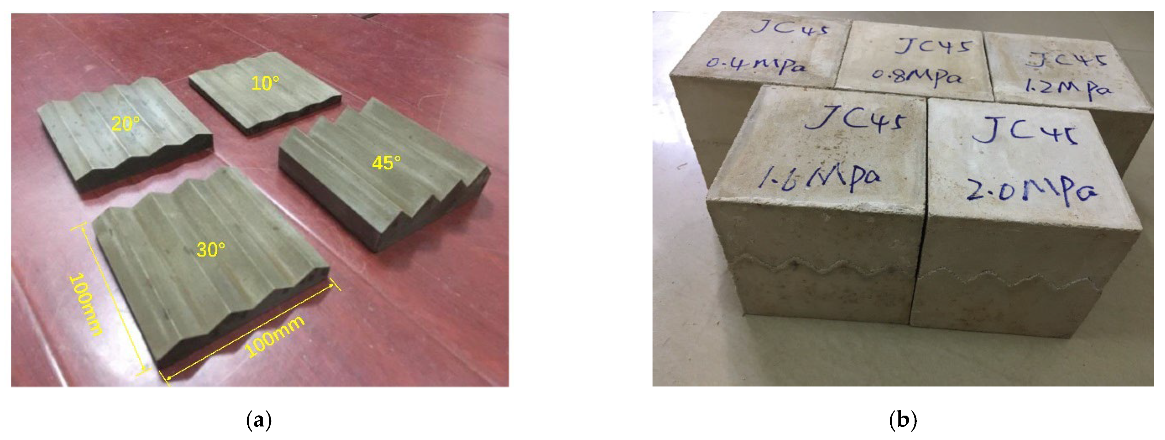
Due to the high discreteness and complex preparation process of natural rock masses, rock-like materials based on the similarity principle were used to carry out the direct shear test [32,33,34,35]. The specimens were divided into upper and lower parts, with the joints as the dividing line. The lower test block and the complete test block are shown in Figure 2. The size of the sample was 100 mm × 100 mm × 100 mm. The model used in this test was a cement mortar specimen, and river sand, white cement and water were selected as raw materials. The material specifications used were white silicate cement with a grade of 425 and fine river sand without mud with a grain size of 0.5~1 mm, and the model was poured according to the mass ratio of water: cement: sand = 1:2:1. The joints contained 4 sawteeth with a length of 25 mm and angles of 10°, 20°, 30°, and 45°, respectively, and shear tests were carried out under five different normal stresses for each sawtooth angle of the joints. The preparation of specimens can be summarized as follows: (1) The square steel template was placed in the center of the cube mold, and the pre-mixed slurry material was gradually poured into the cube mold to create the lower part of the sawtooth joint specimen. (2) After 12 h, the square steel template was taken out of the mold, and the same material was poured into the empty space in the cube mold to produce the upper part. (3) After both the upper and lower parts of the specimen had been prepared, they were kept moist at room temperature for at least 28 days. In addition, straight joints with a sawtooth angle of 0° were also prepared for further comparative analysis. Finally, for each of the five different stress conditions at each sawtooth angle, three specimens were prepared in order to select the piece with the best stress–strain curve as the object of study; therefore, there were a total of 75 specimens with five different normal stresses at five sawtooth angles.
After the specimens had been prepared, basic mechanical tests were carried out first, and thus the pertinent mechanical parameters were obtained: uniaxial compressive strength—15.7 MPa; cohesion—3.12 MPa; internal friction angle—60.42°. Then, with the sawtooth angle of the joints as the standard, the specimens were divided into five groups, and direct shear tests were carried out under values of normal stress of 0.4 MPa, 0.8 Mpa, 1.2 Mpa, 1.6 Mpa and 2.0 Mpa, respectively. The test scheme is shown in Table 1. During the shear process, the normal load was applied first, and the horizontal load was applied at a loading rate of 1 mm/min when the normal load had stabilized to the set value, until the shear displacement reached the set value. After completion of the tests, the test data were recorded and processed, and the damaged surface was photographed.
3. Test Results and Analysis
3.1. Shear Stress–Shear Displacement Curve
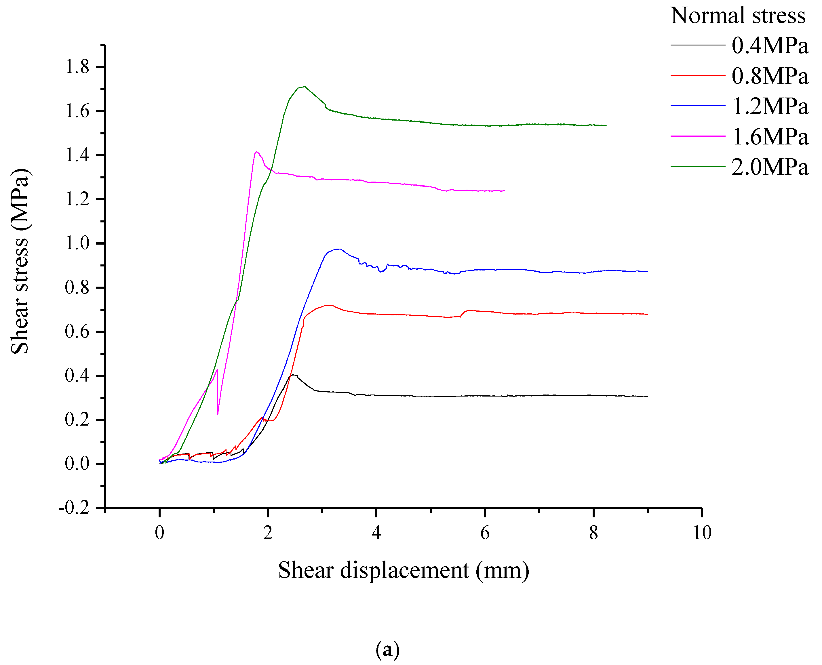
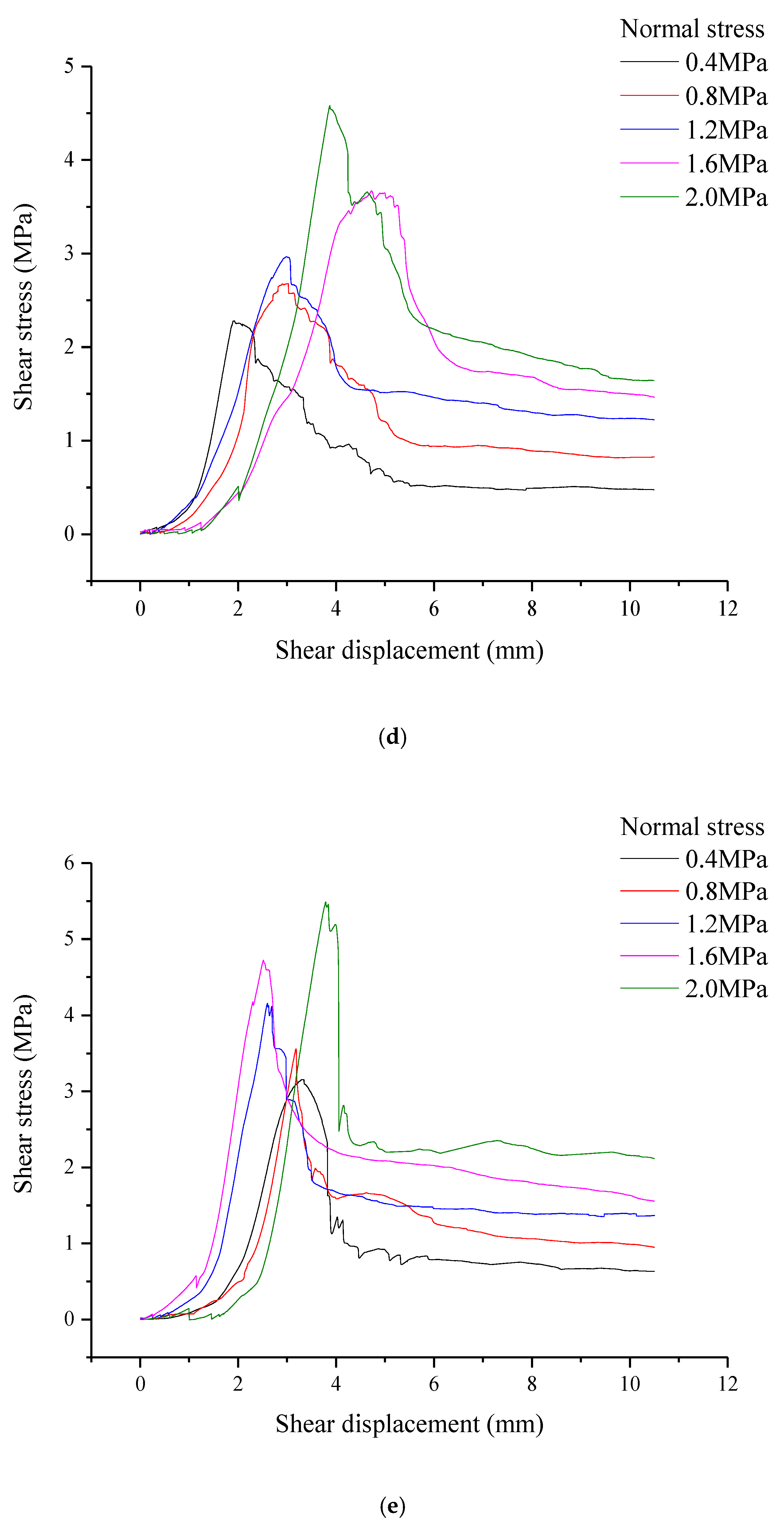
After processing the test data, the shear stress–shear displacement relationship curve of the sawtooth joints under different normal stresses was obtained, as shown in Figure 3. At each sawtooth angle, the shear stress–shear displacement curves show similar characteristics: shear stress increases with increasing shear displacement, and when the shear stress reaches its peak, it drops and stabilizes at the residual shear strength. It should be noted that when the sawtooth angle of the joint is small, such as 0°, 10°, or 20°, the drop from shear strength to residual shear strength is small. Then, when the sawtooth angle of the joint increases to 30°, the drop in shear stress becomes obvious. When the sawtooth angle of the joint increases to 45°, the drop degree of shear stress increases further, and the size of the drop also reaches its maximum. In addition, when the sawtooth angle is between 0° and 30°, the relationship between the peak shear displacement and the normal stress is similar: the peak shear displacement first increases and then decreases with increasing normal stress, but the normal stress with the turning trend is different under different sawtooth angles. When the sawtooth angle is 0°, the positive correlation between peak shear displacement and normal stress ends at 1.6 MPa, while when the sawtooth angle is 10°, 20° or 30°, this correlation ends at 2.0 MPa.
3.2. Shear Characteristics Analysis Based on Mohr–Coulomb Criterion
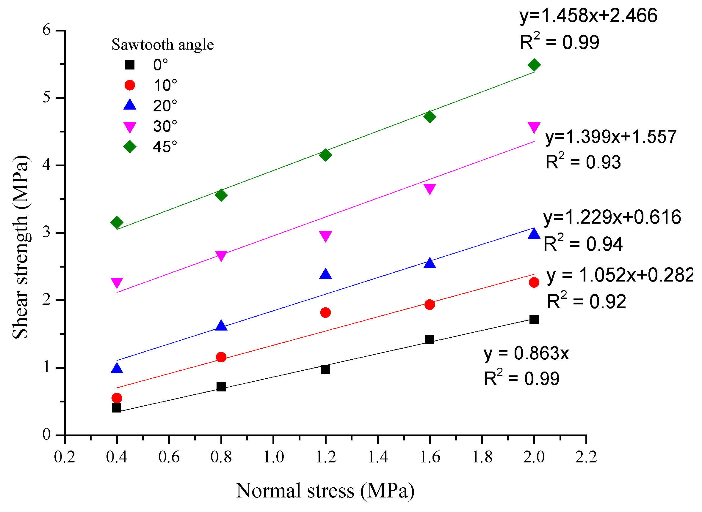
To illustrate the relationship between shear strength and normal stress more intuitively, the shear strengths corresponding to different normal stresses and sawtooth angles were analyzed in the regression analysis [36,37], as shown in Figure 4. Under different sawtooth angles, the shear strength increases with increasing normal stress, and there is a positive linear correlation between the shear strength and normal stress. When the sawtooth angle increases, the slope and intercept of the fitting curve increase, accordingly.
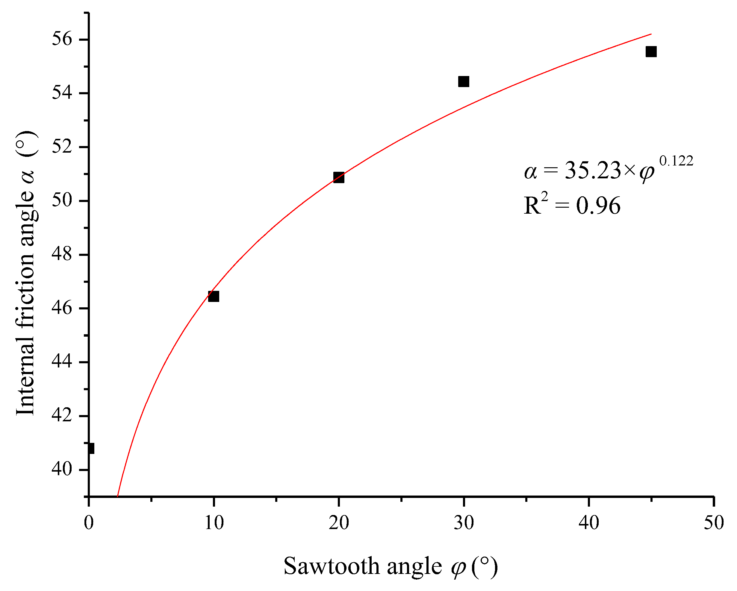
The Mohr–Coulomb criterion was used to obtain the cohesion c and the internal friction angle α of joints at each sawtooth angle [38,39,40,41], as shown in Table 2. The shear strength parameters of joints, cohesion c, and internal friction angle α increased with increasing sawtooth angle. With respect to the properties of the rock materials, the cohesion and internal friction angle are constant. In this test, the shear strength parameters increase with increasing sawtooth angle, because the increase in the sawtooth angle causes the shear failure mechanism to transform from the climbing effect to the tooth cutting effect, and the higher the proportion of the tooth cutting effect, the greater the corresponding cohesion and internal friction angle. Nonlinear relations were used to analyze the relationship between the sawtooth angle and cohesion and internal friction angle, and the fitting results were in good consistency with the test results, as shown in Figure 5 and Figure 6. The relationship between sawtooth angle, cohesion, and internal friction angle is shown in Equation (1). Cohesion and internal friction angle increase nonlinearly with increasing sawtooth angle, but the trend is different. The increasing trend of cohesion increases with increasing sawtooth angle, while the increasing trend of the internal friction angle decreases with increasing sawtooth angle.
3.3. Empirical Equation for Shear Strength of Joints
In general, based on the Mohr–Coulomb criterion, the shear strength of joints can be expressed as:
where is the peak shear strength, is the normal stress, c is the cohesion, is the internal friction angle.
To deeply understand the influence of the sawtooth angle of joints on shear strength, the test data are processed to obtain Figure 5, Figure 6 and Figure 7, which reflects the relationship between sawtooth angle and shear strength. Under all normal stress conditions, the shear strength increases with the increase in the sawtooth angle from 0° to 45°, which clearly shows that there is a positive correlation between the sawtooth angle and the shear strength.
It is clear from Figure 5 and Figure 6 that the sawtooth angle has an important effect on the shear strength of joints, and there is an obvious strengthening function between the cohesion and internal friction angle and the sawtooth angle. Therefore, for sawtooth joints with obvious morphological characteristics, the functional relationship between the cohesion and the internal friction angle is introduced in Equation (2), and the shear strength equation considering the sawtooth is established:
where and are the increment of internal friction angle and cohesion caused by sawtooth angle.
Figure 8 was obtained on the basis of the linear analysis of the increment of internal friction angle caused by the sawtooth angle. According to Figure 5 and Figure 8, the functional relationship between cohesion and the internal friction angle and sawtooth angle can be expressed as follows:
By introducing Equations (4) and (5) into Equation (3), an empirical equation for shear strength considering sawtooth angle can be obtained:
Based on the internal friction angle and sawtooth angle, the empirical equation can calculate the shear strength under certain normal stress, which provides a theoretical reference for the prediction and prevention of natural disasters.
3.4. Analysis of Failure Mechanism
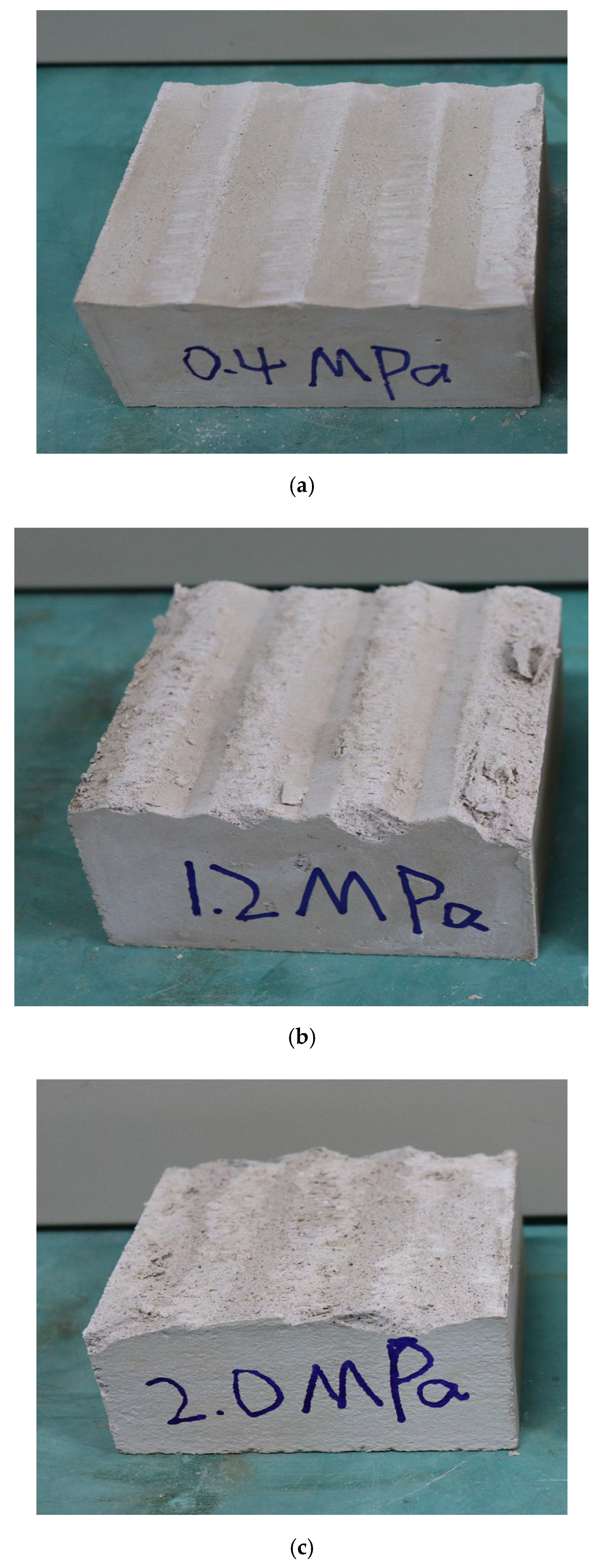
On the basis of the analysis of the shear test results of joints under different conditions, it was found that the failure mechanism can be divided into two types: the “saw-toothed sliding gnawing failure mechanism” (SSG) and the “tensile fracture mechanism” (TFM). Of these, the SSG failure mechanism mainly includes three failure modes: slip–gnaw failure and complete gnaw failure. Table 3 summarizes the failure modes of joints under different sawtooth angles and normal stresses. With the increase in sawtooth angle and normal stress, the shear failure of joints evolves into a slipping–slip gnawing–complete gnawing mechanism. Figure 9a shows a typical slipping failure, where the shear failure surface has a sawtooth angle of 10° and a normal stress of 0.4 MPa. It can be observed that the morphological characteristics of sliding failure mode hardly change compared with that before shear. In this failure mode, the shear strength is mainly provided by sliding friction between the serrations. Figure 9b presents an example of the slip gnawing failure mode, where the shear failure surface has a sawtooth angle of 20° and a normal stress of 1.2 MPa. In this mode, the failure modes are a combination of slip failure and gnawing failure, and the morphological characteristics are changed significantly compared with those before shearing, this is because the raised sawtooth has a certain inhibitory effect on the sliding of the joint. At this time, the shear strength is composed of the sliding friction and the cohesion of the sawtooth. Figure 9c presents an example of complete gnawing failure, where the shear failure surface has a sawtooth angle of 45° and a normal stress of 2.0 MPa. In this mode, the sawtooth is severely cut off, which is a result of the larger angle of the raised sawtooth and the greater normal stress. At this time, the shear strength is mainly composed of the cohesion of the sawtooth.
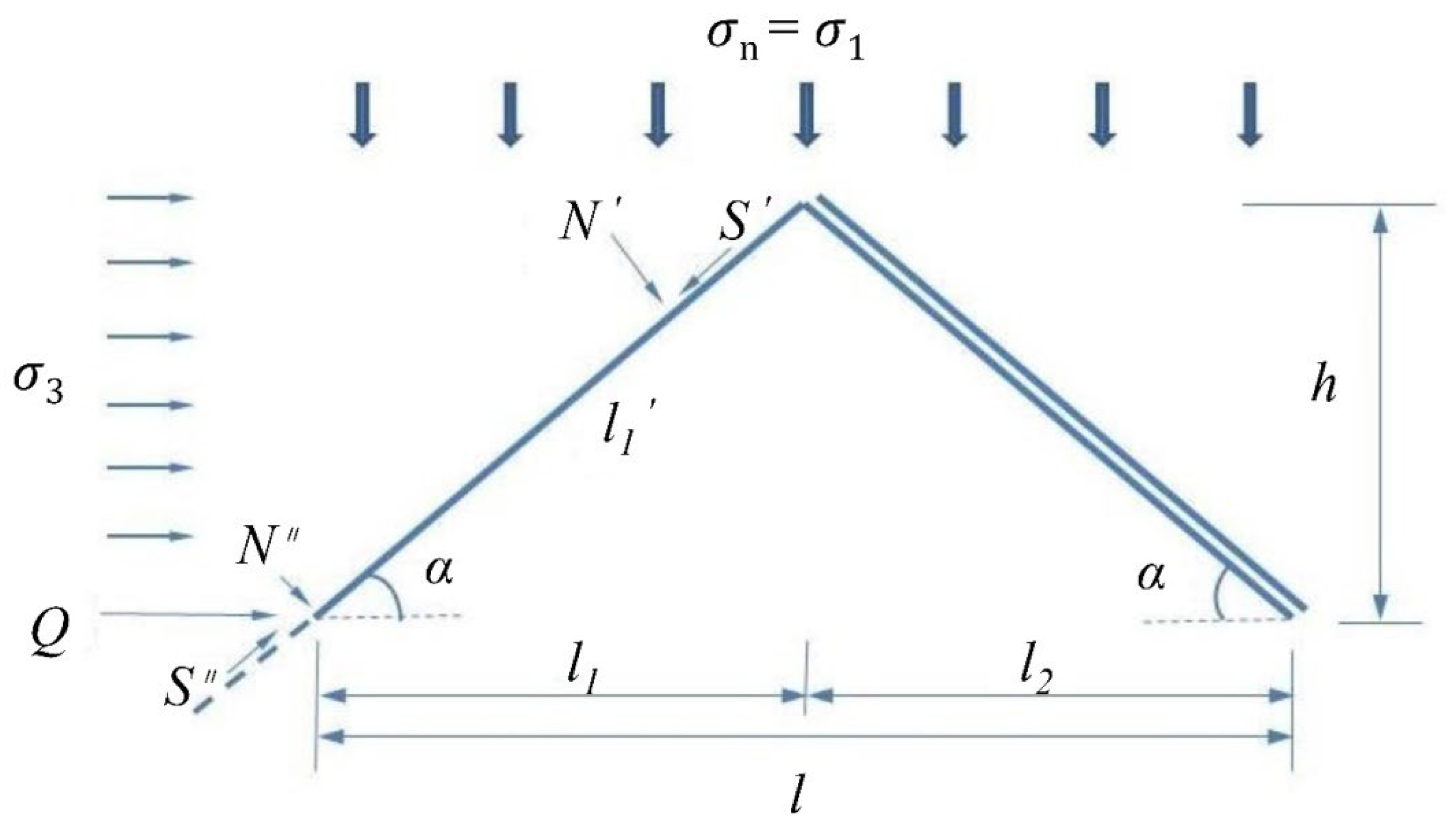
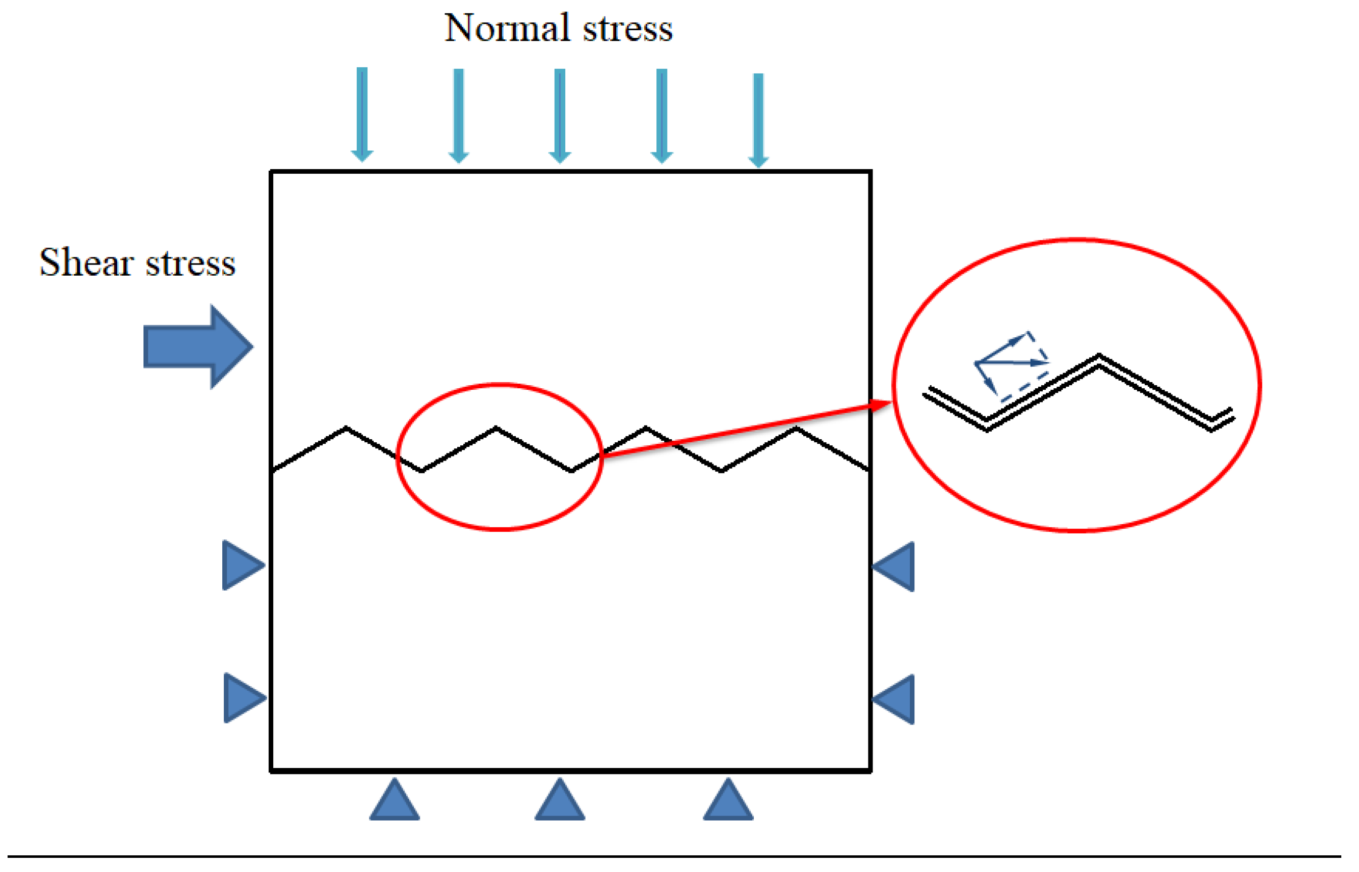
It can be seen from the above that the shear behavior of the sawtooth joints is affected by the morphology of the shear direction. A mechanical model analysis was performed on the failure mode of SSG. When the joint climbs along the sawtooth during the shearing process, the contact between the joints of the back slope separates, and the normal load at that time is completely concentrated on the climbing surface. Therefore, the mechanical properties of the climbing surface are studied. Figure 10 shows the mechanical model of the sawtooth joints during the shearing process, and the geometric relationship of the sawtooth is:
According to the force analysis in Figure 10, the normal force acting on the sawtooth is:
The shear stress acting on the sawtooth is:
The normal force P and shear stress S acting on the sawtooth are decomposed along the sawtooth surface, and the following equation can be obtained:
where N is the resultant force perpendicular to the joint, T is the resultant force parallel to the joint, and S is the total shear force acting on the sawtooth in the horizontal direction.
According to the limit equilibrium condition, it can be known that:
Combining Equations (7)–(12), we can get:
Along the direction of the joint, the conditions of limit equilibrium are:
In combination with Equations (14) and (15), the following equation can be obtained:
That is, the shear strength parameter of the joints when the sawtooth climbs and slips are:
Under low normal stress conditions, the shear strength of the joint conforms to the conditions of Equations (17) and (18), and the shearing behavior is dominated by the climbing mode. When the strength of the rock mass is low or the normal stress is large, the shear failure mode changes to the slip gnawing mode. At this time, the shear force when the sawtooth with length l is gnawed is TB, which can be solved as follows:
Substituting Equations (20) and (21) into Equation (18), we can get:
where is the cohesion of the sawtooth when it is gnawed.
Equation (22) is the normal stress on the joint when climbing action is transformed into gnawing action. When the normal stress , the failure of the joint mainly consists of gnawing failure, and when , the failure mode mainly consists of climbing failure.
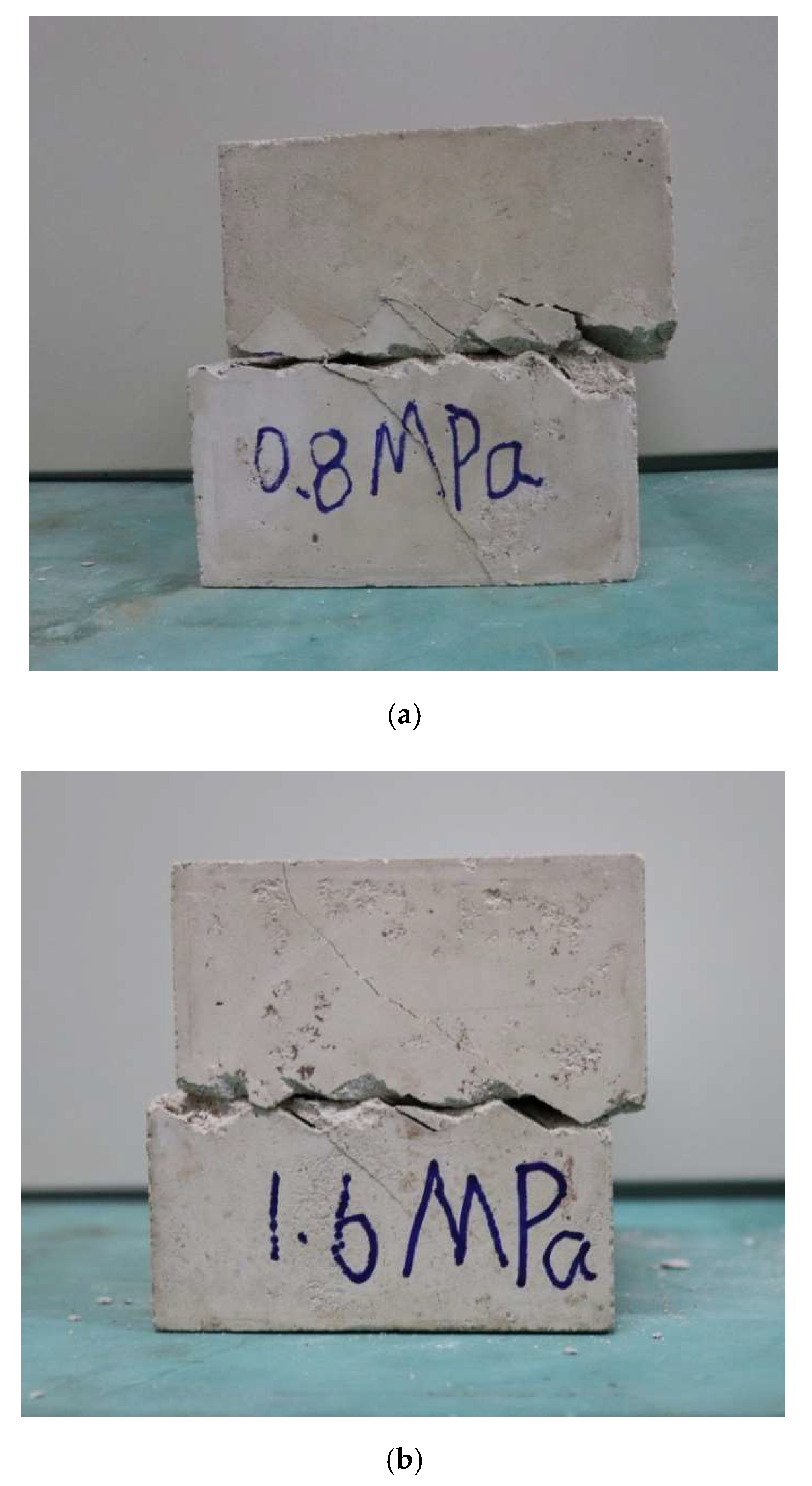
The “tensile fracture mechanism” failure mode mainly shows that cracks appear near the joint. In this shear failure mode, there is no friction trace on the crack surface, indicating that these cracks are caused by tensile fracture rather than shear. The failure mode of TFM is shown in Figure 11. On the basis of a comparative study, it was found that the following rules exist for the generation of tensile fracture cracks: the dip angle forms an acute angle with horizontal shear direction, and most of the cracks start at the root of the sawtooth. The sawtooth forces in this mode can be analyzed as shown in Figure 12. The generation mechanism of cracks is as follows: the joint begins to be affected by horizontal force after the application of normal stress. Both the normal force and the tangential force exert a tensile effect on the sawtooth, and the stress concentration phenomenon occurs at the root of the sawtooth, so the tensile cracks all start at the root of the sawtooth. According to the statistics of the test results, it was found that when the sawtooth angle is 45°, the specimens develop the greatest number of tensile cracks under various normal stresses, followed by the specimens with the sawtooth angle of 30°, while almost no tensile cracks appear when the sawtooth angle is 20°. This is because with large sawtooth angles, the sawtooth has a greater resistance to the dislocation of the joint, and it is easy for tensile stress to be concentrated at the root of the sawtooth. Therefore, at small sawtooth angles, the resistance of the sawtooth to the joint is low, and relative sliding occurs more easily, so that no concentration of tensile stresses is generated.
4. Conclusions
- (1)
- The shear stress under each sawtooth angle increased with increasing shear displacement. When the sawtooth angle of the joints was small, there was not a significant decrease between the shear strength and the residual shear strength, and the size of the drop was also smaller. The peak shear displacement showed a trend of first increasing and then decreasing with increasing normal stress, but the normal stress corresponding to the transition at different sawtooth angles was different.
- (2)
- The shear strength of joints at each sawtooth angle increased with the increase of the normal stress. The Mohr–Coulomb criterion was used to analyze the shear strength of the joints. It was found that the cohesion c and the internal friction angle α both increased nonlinearly with increasing sawtooth angle, but the increasing trend was different.
- (3)
- By introducing the function relation between cohesion and the internal friction angle and sawtooth angle into the shear strength formula of joints, an empirical equation for shear strength considering sawtooth angle was established.
- (4)
- The shear failure of sawtooth joints can be divided into two modes: the “saw-toothed sliding gnawing failure mechanism” (SSG) and the “tensile fracture mechanism” (TFM). With increasing sawtooth angle and normal stress, the shear failure mode ranges from slipping to slip gnawing to complete gnawing. The tensile fracture mechanism mainly occurs at high sawtooth angles.
Author Contributions
Conceptualization, H.H. and H.L.; methodology, H.L.; formal analysis, X.Z.; investigation, J.Q.; resources, H.H.; data curation, X.Z.; writing—original draft preparation, X.Z.; writing—review and editing, H.L. All authors have read and agreed to the published version of the manuscript.
Funding
Hunan provincial key research and development Program (2022SK2082); Science and Technology Project of Hunan Natural Resources Department (2021-52); Science and Technology Progress and Innovation Plan of Hunan Provincial Department of Transportation (201003); Science and Technology Progress and Innovation Plan of Hunan Provincial Department of Transportation (202120); Hunan Civil Air Defense Research Project (HNRFKJ-2021-07). The authors wish to acknowledge this support.
Institutional Review Board Statement
Not applicable.
Informed Consent Statement
Not applicable.
Data Availability Statement
The data used to support the findings of this study are available from the corresponding author upon request.
Acknowledgments
This paper received funding from Hunan provincial key research and development Program (2022SK2082); Science and Technology Project of Hunan Natural Resources Department (2021-52); Science and Technology Progress and Innovation Plan of Hunan Provincial Department of Transportation (201003); Science and Technology Progress and Innovation Plan of Hunan Provincial Department of Transportation (202120); Hunan Civil Air Defense Research Project (HNRFKJ-2021-07). The authors wish to acknowledge this support.
Conflicts of Interest
The authors declare no conflict of interest.
References
- Ghazvinian, A.H.; Azinfar, M.J.; Vaneghi, R.G. Importance of Tensile Strength on the Shear Behavior of Discontinuities. Rock Mech. Rock Eng. 2012, 45, 349–359. [Google Scholar] [CrossRef]
- Lin, H.; Sun, P.H.; Chen, Y.F.; Zhu, Y.Y.; Fan, X.; Zhao, Y.L. Analytical and experimental analysis of the shear strength of bolted saw-tooth joints. Eur. J. Environ. Civ. Eng. 2022, 26, 1639–1653. [Google Scholar] [CrossRef]
- Du, S.-G.; Lin, H.; Yong, R.; Liu, G.-J. Characterization of Joint Roughness Heterogeneity and Its Application in Representative Sample Investigations. Rock Mech. Rock Eng. 2022, 55, 1–25. [Google Scholar] [CrossRef]
- Zhao, Y.; Zhang, C.; Wang, Y.; Lin, H. Shear-related roughness classification and strength model of natural rock joint based on fuzzy comprehensive evaluation. Int. J. Rock Mech. Min. Sci. 2021, 137, 104550. [Google Scholar] [CrossRef]
- Antronico, L.; Borrelli, L.; Coscarelli, R.; Gulla, G. Time evolution of landslide damages to buildings: The case study of Lungro (Calabria, southern Italy). Bull. Eng. Geol. Environ. 2015, 74, 47–59. [Google Scholar] [CrossRef]
- Luo, H.Y.; Zhang, L.M.; Wang, H.J.; He, J. Process of building collapse caused by the Po Shan Road landslide in Hong Kong on 18 June 1972. Landslides 2021, 18, 3769–3780. [Google Scholar] [CrossRef]
- Parisi, F.; Sabella, G. Flow-type landslide fragility of reinforced concrete framed buildings. Eng. Struct. 2017, 131, 28–43. [Google Scholar] [CrossRef]
- Du, S.-G.; Saroglou, C.; Chen, Y.; Lin, H.; Yong, R. A new approach for evaluation of slope stability in large open-pit mines: A case study at the Dexing Copper Mine, China. Environ. Earth Sci. 2022, 81, 102. [Google Scholar] [CrossRef]
- Zhao, Y.; Liu, Q.; Zhang, C.; Liao, J.; Lin, H.; Wang, Y. Coupled seepage-damage effect in fractured rock masses: Model development and a case study. Int. J. Rock Mech. Min. Sci. 2021, 144, 104822. [Google Scholar] [CrossRef]
- Wang, F.; Cao, P.; Cao, R.; Gao, Q.; Xiong, X.; Wang, Z. Influence of parallel joint interaction on mechanical behavior of jointed rock mass. J. Central South Univ. 2018, 49, 2498–2507. [Google Scholar]
- Liu, J.; Zhao, Y.; Tan, T.; Zhang, L.; Zhu, S.; Xu, F. Evolution and modeling of mine water inflow and hazard characteristics in southern coalfields of China: A case of Meitanba mine. Int. J. Min. Sci. Technol. 2022, 32, 513–524. [Google Scholar] [CrossRef]
- Kazerani, T.; Yang, Z.Y.; Zhao, J. A Discrete Element Model for Predicting Shear Strength and Degradation of Rock Joint by Using Compressive and Tensile Test Data. Rock Mech. Rock Eng. 2012, 45, 695–709. [Google Scholar] [CrossRef] [Green Version]
- Lei, D.; Lin, H.; Wang, Y. Damage characteristics of shear strength of joints under freeze–thaw cycles. Arch. Appl. Mech. 2022, 92, 1615–1631. [Google Scholar] [CrossRef]
- Fan, X.; Yang, Z.; Li, K. Effects of the lining structure on mechanical and fracturing behaviors of four-arc shaped tunnels in a jointed rock mass under uniaxial compression. Theor. Appl. Fract. Mech. 2021, 112, 102887. [Google Scholar] [CrossRef]
- Huang, C.C.; Yang, W.D.; Duan, K.; Fang, L.D.; Wang, L.; Bo, C.J. Mechanical behaviors of the brittle rock-like specimens with multi-non-persistent joints under uniaxial compression. Constr. Build. Mater. 2019, 220, 426–443. [Google Scholar] [CrossRef]
- Jang, H.S.; Jang, B.A. New Method for Shear Strength Determination of Unfilled, Unweathered Rock Joint. Rock Mech. Rock Eng. 2015, 48, 1515–1534. [Google Scholar] [CrossRef]
- Oh, J.; Li, Y.; Mitra, R.; Canbulat, I. A Numerical Study on Dilation of a Saw-Toothed Rock Joint Under Direct Shear. Rock Mech. Rock Eng. 2017, 50, 913–925. [Google Scholar] [CrossRef]
- Xie, S.; Lin, H.; Cheng, C.; Chen, Y.; Wang, Y.; Zhao, Y.; Yong, W. Shear strength model of joints based on Gaussian smoothing method and macro-micro roughness. Comput. Geotech. 2022, 143, 104605. [Google Scholar] [CrossRef]
- Barton, N.; Choubey, V. The shear strength of rock joints in theory and practice. Rock Mech. Rock Eng. 1977, 10, 1–54. [Google Scholar] [CrossRef]
- Li, K.-H.; Cao, P.; Zhang, K.; Zhong, Y.-F. Macro and meso characteristics evolution on shear behavior of rock joints. J. Central South Univ. 2015, 22, 3087–3096. [Google Scholar] [CrossRef]
- Shi, J.C.; Li, J.C.; Li, X.; He, L. Effect of joint surface roughness on normal stiffness and morphology in rock masses under cyclic impact. J. Central South Univ. 2021, 52, 2661–2668. [Google Scholar] [CrossRef]
- Lee, Y.K.; Park, J.W.; Song, J.J. Model for the shear behavior of rock joints under CNL and CNS conditions. Int. J. Rock. Mach. Min. Sci. 2014, 70, 252–263. [Google Scholar] [CrossRef]
- Singh, H.K.; Basu, A. Evaluation of existing criteria in estimating shear strength of natural rock discontinuities. Eng. Geol. 2018, 232, 171–181. [Google Scholar] [CrossRef]
- Xia, C.C.; Tang, Z.C.; Xiao, W.M.; Song, Y.L. New Peak Shear Strength Criterion of Rock Joints Based on Quantified Surface Description. Rock Mech. Rock Eng. 2014, 47, 387–400. [Google Scholar] [CrossRef]
- Sanei, M.; Faramarzi, L.; Fahimifar, A.; Goli, S.; Mehinrad, A.; Rahmati, A. Shear strength of discontinuities in sedimentary rock masses based on direct shear tests. Int. J. Rock. Mach. Min. Sci. 2015, 75, 119–131. [Google Scholar] [CrossRef]
- Li, S.; Lin, H.; Feng, J.; Cao, R.; Hu, H. Mechanical Properties and Acoustic Emission Characteristics of Anchored Structure Plane with Different JRC under Direct Shear Test. Materials 2022, 15, 4169. [Google Scholar] [CrossRef]
- Chen, Y.; Lin, H.; Xie, S.; Ding, X.; He, D.; Yong, W.; Gao, F. Effect of joint microcharacteristics on macroshear behavior of single-bolted rock joints by the numerical modelling with PFC. Environ. Earth Sci. 2022, 81, 276. [Google Scholar] [CrossRef]
- Tang, Z.C.; Zhang, Q.Z.; Peng, J.; Jiao, Y.Y. Experimental study on the water-weakening shear behaviors of sandstone joints collected from the middle region of Yunnan province, P.R. China. Eng. Geol. 2019, 258, 105161. [Google Scholar] [CrossRef]
- Kong, W.; Li, Y.; Nie, L.; Dong, Z.; Cai, W.; Wang, Z.; Wang, K. Experimental and numerical investigations on crack propagation characteristics of rock-like specimens with preexisting flaws subjected to combined actions of internal hydraulic pressure and shear force. Arch. Appl. Mech. 2022, 92, 221–239. [Google Scholar] [CrossRef]
- Zhao, Y.; Chang, L.; Wang, Y.; Lin, H.; Liao, J.; Liu, Q. Dynamic response of cylindrical thick-walled granite specimen with clay infilling subjected to dynamic loading. Arch. Appl. Mech. 2022, 92, 643–648. [Google Scholar] [CrossRef]
- Shen, Y.; Yang, H.; Xi, J.; Yang, Y.; Yongzhi, W.; Wei, X. A novel shearing fracture morphology method to assess the influence of freeze–thaw actions on concrete–granite interface. Cold Reg. Sci. Technol. 2019, 169, 102900. [Google Scholar] [CrossRef]
- Fan, X.; Yu, H.; Deng, Z.; He, Z.; Zhao, Y. Cracking and deformation of cuboidal sandstone with a single nonpenetrating flaw under uniaxial compression. Theor. Appl. Fract. Mech. 2022, 119, 103284. [Google Scholar] [CrossRef]
- Xie, S.J.; Lin, H.; Chen, Y.F.; Wang, Y.X. A new nonlinear empirical strength criterion for rocks under conventional triaxial compression. J. Central South Univ. 2021, 28, 1448–1458. [Google Scholar] [CrossRef]
- Tang, W.; Lin, H.; Chen, Y.; Feng, J.; Hu, H. Mechanical Characteristics and Acoustic Emission Characteristics of Mortar-Rock Binary Medium. Buildings 2022, 12, 665. [Google Scholar] [CrossRef]
- Liu, B.; Lin, H.; Chen, Y. Deformation Characteristics of Bolted Rock Joints under Compression-Shear Load. Appl. Sci. 2022, 12, 5226. [Google Scholar] [CrossRef]
- Zhou, K.; Liu, C.; Li, S.; Cheng, Y. Size Effect on the Rheological Shear Mechanical Behaviors of Different Joints: A Numerical Study. Geofluids 2022, 2022, 7484209. [Google Scholar] [CrossRef]
- Han, L.; Lin, H.; Chen, Y.; Lei, D. Effects of strength property difference on shear strength of joint of binary media. Environ. Earth Sci. 2021, 80, 1–10. [Google Scholar] [CrossRef]
- Zhang, C.; Wang, Y.; Ruan, H.; Ke, B.; Lin, H. The strain characteristics and corresponding model of rock materials under uniaxial cyclic load/unload compression and their deformation and fatigue damage analysis. Arch. Appl. Mech. 2021, 91, 2481–2496. [Google Scholar] [CrossRef]
- Zhang, C.; Wang, Y.; Jiang, T. The propagation mechanism of an oblique straight crack in a rock sample and the effect of osmotic pressure under in-plane biaxial compression. Arab. J. Geosci. 2020, 13, 736. [Google Scholar] [CrossRef]
- Chen, Y.; Lin, H.; Cao, R.; Zhang, C. Slope Stability Analysis Considering Different Contributions of Shear Strength Parameters. Int. J. Geomech. 2021, 21, 04020265. [Google Scholar] [CrossRef]
- Zhao, Y.; Zhang, L.; Wang, W.; Liu, Q.; Tang, L.; Cheng, G. Experimental Study on Shear Behavior and a Revised Shear Strength Model for Infilled Rock Joints. Int. J. Geomech. 2020, 20, 0402014. [Google Scholar] [CrossRef]
Figure 1.
Landslide and collapse caused by joints.

Figure 2.
Test specimens. (a) Lower test block of joints; (b) Prepared specimens.

Figure 3.
Shear stress–shear displacement curves of joints with different sawtooth angles: (a) Sawtooth angle of 0°; (b) Sawtooth angle of 10°; (c) Sawtooth angle of 20°; (d) Sawtooth angle of 30°; (e) Sawtooth angle of 45°.
Figure 3.
Shear stress–shear displacement curves of joints with different sawtooth angles: (a) Sawtooth angle of 0°; (b) Sawtooth angle of 10°; (c) Sawtooth angle of 20°; (d) Sawtooth angle of 30°; (e) Sawtooth angle of 45°.


Figure 4.
Shear strength under different normal stresses.

Figure 5.
Relationship between cohesion and sawtooth angle.

Figure 6.
Relationship between internal friction angle and sawtooth angle.

Figure 7.
Relationship between shear strength and sawtooth angle.

Figure 8.
Influence of sawtooth angle on the internal friction angle.

Figure 9.
Saw-toothed sliding gnawing failure mechanism of joints. (a) Slip failure at 10° sawtooth angle under 0.4 MPa normal stress; (b) Slip gnawing failure at 20° sawtooth angle under 1.2 MPa normal stress; (c) Complete gnawing failure at 45° sawtooth angle under 2.0 MPa normal stress.
Figure 9.
Saw-toothed sliding gnawing failure mechanism of joints. (a) Slip failure at 10° sawtooth angle under 0.4 MPa normal stress; (b) Slip gnawing failure at 20° sawtooth angle under 1.2 MPa normal stress; (c) Complete gnawing failure at 45° sawtooth angle under 2.0 MPa normal stress.

Figure 10.
Shear mechanical model of the sawtooth joint.

Figure 11.
Tensile fracture mechanism. (a) Tensile crack of 45° sawtooth angle under 0.8 MPa normal stress. (b) Tensile crack of 30° sawtooth angle under 1.6 MPa normal stress.
Figure 11.
Tensile fracture mechanism. (a) Tensile crack of 45° sawtooth angle under 0.8 MPa normal stress. (b) Tensile crack of 30° sawtooth angle under 1.6 MPa normal stress.

Figure 12.
Stress diagram of sawtooth.


Table 1.
Test scheme.
| Sawtooth Angle/° | Normal Stress/MPa | Loading Rate | Number of Samples |
|---|---|---|---|
| 0 | 0.4, 0.8, 1.2, 1.6, 2.0 | 1 mm/min | 15 |
| 10 | 15 | ||
| 20 | 15 | ||
| 30 | 15 | ||
| 45 | 15 |
Table 2.
Shear strength parameters of joints.
| Sawtooth Angle φ (°) | Cohesion c (Mpa) | Internal Friction Angle α (°) |
|---|---|---|
| 0 | 0 | 40.79 |
| 10 | 0.282 | 46.45 |
| 20 | 0.616 | 50.87 |
| 30 | 1.557 | 54.44 |
| 45 | 2.466 | 55.55 |
Table 3.
Failure mode statistics of sawtooth joints.
| Sawtooth Angle (°) | Normal Stress (MPa) | ||||
|---|---|---|---|---|---|
| 0.4 | 0.8 | 1.2 | 1.6 | 2.0 | |
| 10 | Slipping | Slip gnawing | |||
| 20 | Slipping | Slip gnawing | |||
| 30 | Slip gnawing | Complete gnawing | |||
| 45 | Slip gnawing | Complete gnawing | |||
Publisher’s Note: MDPI stays neutral with regard to jurisdictional claims in published maps and institutional affiliations. |
© 2022 by the authors. Licensee MDPI, Basel, Switzerland. This article is an open access article distributed under the terms and conditions of the Creative Commons Attribution (CC BY) license (https://creativecommons.org/licenses/by/4.0/).
Share and Cite
MDPI and ACS Style
Hu, H.; Zhang, X.; Qin, J.; Lin, H. Influence of Morphology Characteristics on Shear Mechanical Properties of Sawtooth Joints. Buildings 2022, 12, 886. https://doi.org/10.3390/buildings12070886
AMA Style
Hu H, Zhang X, Qin J, Lin H. Influence of Morphology Characteristics on Shear Mechanical Properties of Sawtooth Joints. Buildings. 2022; 12(7):886. https://doi.org/10.3390/buildings12070886
Chicago/Turabian StyleHu, Huihua, Xing Zhang, Jianxin Qin, and Hang Lin. 2022. "Influence of Morphology Characteristics on Shear Mechanical Properties of Sawtooth Joints" Buildings 12, no. 7: 886. https://doi.org/10.3390/buildings12070886
Note that from the first issue of 2016, this journal uses article numbers instead of page numbers. See further details here.