
Experimental Evaluation of Brick Masonry Walls Strengthened with TRM (Textile Reinforced Mortar) Renders


1
LNEC, National Laboratory of Civil Engineering, 1700-066 Lisbon, Portugal
2
CERIS, Instituto Superior Técnico, Universidade de Lisboa, 1049-001 Lisbon, Portugal
*
Author to whom correspondence should be addressed.
Buildings 2022, 12(6), 840; https://doi.org/10.3390/buildings12060840
Submission received: 18 April 2022
/
Revised: 1 June 2022
/
Accepted: 13 June 2022
/
Published: 16 June 2022
(This article belongs to the Collection Green and Sustainable Building Materials)
Abstract
:Old masonry buildings, which are frequently part of the cities-built heritage, are vulnerable to seismic actions. Thus, it is important to conduct efficient seismic strengthening interventions that allow maintenance of the existing building to minimize the environmental and economic impact. The use of reinforced renders is a simple and effective solution for seismic strengthening of this type of constructions. In this paper, several compositions of reinforced renders are analyzed, consisting of mortars with air lime, hydraulic lime, or cement binders, reinforced with steel mesh, fiberglass mesh and a natural fiber mesh. Additionally, the results of diagonal compression tests on three small wall specimens are presented, one of which is non-reinforced and the other two are strengthened with reinforced renders. The results of all tested walls are presented and compared, allowing us to evaluate the efficiency of the reinforced render on the wall shear strength.
1. Introduction
Reinforced renders are a particularly promising solution for the rehabilitation and strengthening of old buildings, particularly adapted for a sustainable intervention with minimum consumption of new materials, minimum waste production, and respect for cultural heritage. This solution is usually composed of a reinforcement material with high tensile strength embedded within a mortar that is applied to the external surface of the structural elements.
The reinforcement materials used in reinforced renders may be in the form of loose fibers or fiber meshes and may be of various types [1]. The most sustainable fibers include wool, cotton, wood, straw, reed, bamboo, horsehair, sisal, jute, coconut fiber, and others [2]. On the other hand, the fibers of greater strength and efficiency for increasing the tensile strength of the mortar are steel fibers, carbon [3,4,5,6,7], and basalt [8]. Glass fibers (resistant to alkalis) [9] show an intermediate performance.
The mortars used in reinforced renders can be based on cement, hydraulic lime, hydrated lime, or mixed binders, for example cement and resin or cement and hydrated lime. The most resistant among these types of mortars are those of cement or cement and resin, while the most compatible with old buildings and more sustainable, but also with less mechanically resistant, are those of hydrated lime. Natural hydraulic lime mortars can be a reasonable compromise if they are found to be sufficiently effective. The choice of the type of mortar to be used depends on the properties of the substrate where these reinforced renders will be applied, as well as the level of performance required.
The evaluation of the masonry properties is also important to support a correct diagnosis of the actual condition of the wall structure. This procedure helps choosing the materials and techniques that are best suited to a proper structural rehabilitation. The lack of knowledge of the main characteristics of masonry structures, such as its shear strength, sometimes leads to interventions with less adequate techniques, jeopardizing the authenticity of the built heritage.
The evaluation of strengthening solutions applied to masonry walls is essential to determine their effectiveness compared to unreinforced walls. The experimental tests aimed at quantifying the in-plane strength-improvement achieved with these strengthening solutions. Additionally, evaluated was the mechanical compatibility between the walls and the strengthening materials.
Besides allowing significant improvement in seismic behavior, these solutions also allow protecting and preserving the architectural heritage. The strengthening solutions studied also satisfy principles of compatibility, in its various aspects, and of the greatest possible reversibility, including the least intrusion into the existing elements.
Several combinations of reinforced mortars were considered, consisting of mortars with binders of hydrated lime, natural hydraulic lime, or Portland cement, with balanced compositions, and three types of reinforcement mesh—a steel mesh, a glass fiber mesh, and a mesh of natural jute fibers. Two of these solutions were chosen and applied to the small wall specimens (wallettes) that were later subjected to diagonal compression tests. An unreinforced wall was also assessed for comparison purposes to evaluate the effectiveness of the chosen strengthening solutions.
2. Tensile Tests on Reinforced Renders
2.1. Specimen Preparation
For the execution of test specimens, three types of reinforcement mesh were selected—a steel mesh (tension strength of 362 MPa/28.5 kN/m, ultimate deformation of 8.3%), a glass fiber mesh (782 MPa/97.6 kN/m, 2.1%) and a natural jute mesh (55 MPa/4.2 kN/m, 3.1%). Four types of mortar were also selected, consisting of binders based on hydrated lime, with 1/3 binder/sand ratio, natural hydraulic lime, with 1/2 and 1/3 ratios, and Portland cement, with 1/3 ratio. Table 1 shows the composition of the various specimens of reinforced mortars under study, as well as their identification.
The tested specimens of reinforced mortars (five specimens for each mortar composition/mesh type) were 60 cm long, 10 cm wide, and 2 cm thick. The reinforced mesh was 80 cm long and 10 cm wide and was in the half-thickness of each specimen.
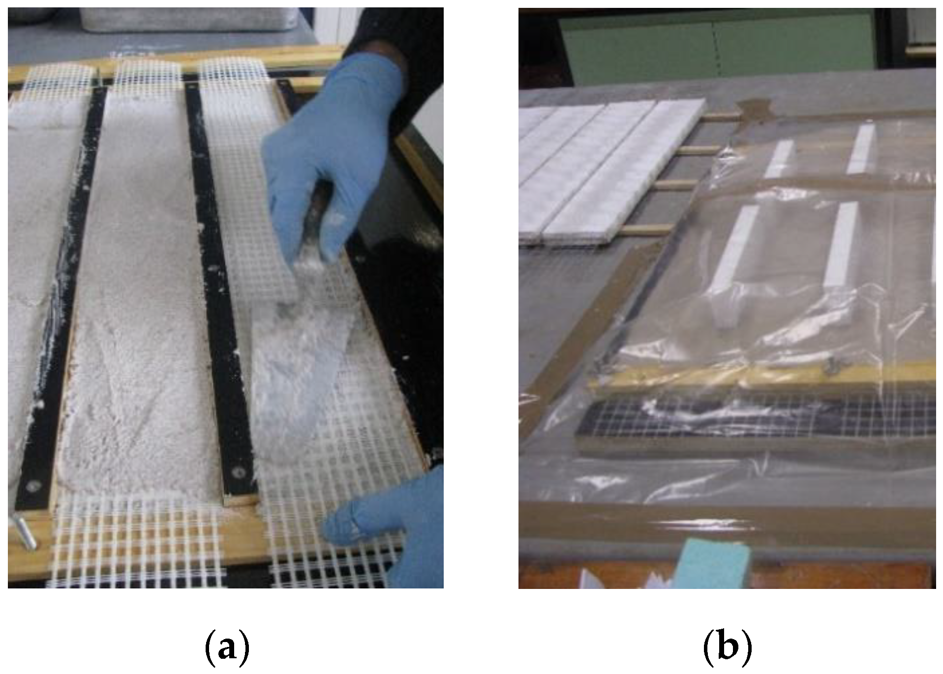
The reinforced mortar specimens were molded in two layers using maritime plywood formwork. The first layer is approximately 1 cm thick, the mesh is then deployed, as shown in Figure 1a, and, finally, the second layer is applied and leveled.
The type and time of curing (Figure 1b) followed the standard EN 1015-11 [10]. After the initial curing procedures, the specimens were placed in a conditioning room at a temperature of 20 °C ± 2%, and relative humidity of 65% ± 5% until the date of the test. Cement specimens were cured for 28 days, while lime specimens were cured for 90 days.
2.2. Experimental Campaign
After the specimens’ cured, they were subjected to the tensile tests. Given the fragility of the specimens, due to their slenderness, there was a need to adopt some precautions when handling them. The specimens were transported to the test site as their curing period was completed. At this stage, the specimens were identified, measured, weighed, and inspected with a magnifying glass. Ultrasound tests were also conducted on each specimen to check for cracks that could have been caused by demolding or transportation.
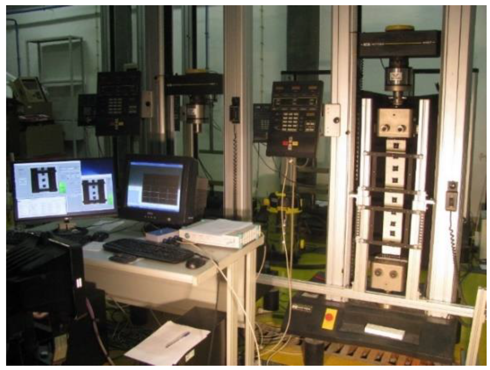
The tensile tests were conducted with displacement control with a speed of 0.6 mm/min and a sampling frequency of 50 Hz. Figure 2 shows the execution of one of the tensile tests at the specimen’s rupture.
2.3. Results Obtained
The load values applied in the specimens during the tensile tests were recorded and the value of the stress at the fiber mesh (in the cracks, where it bears the whole load) was calculated, considering the cross-sectional area of the longitudinal fibers.
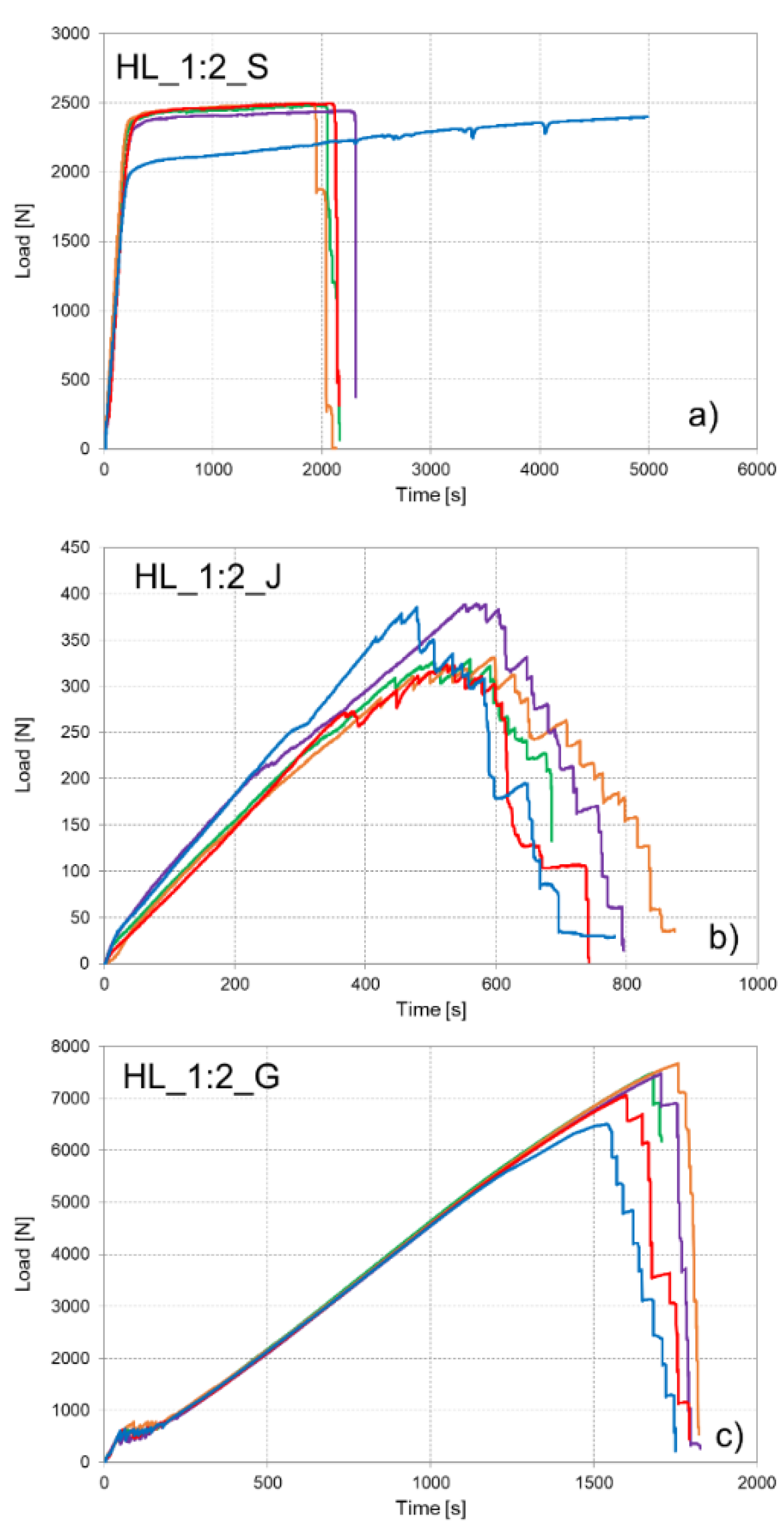
Figure 3 shows examples of a load vs. time diagram obtained in reinforced mortars of natural hydraulic lime mortar in the 1/2 binder/sand ratio in each of the three studied meshes. It should be noted that the diagrams are not on the same scale because the strengths obtained are quite different.
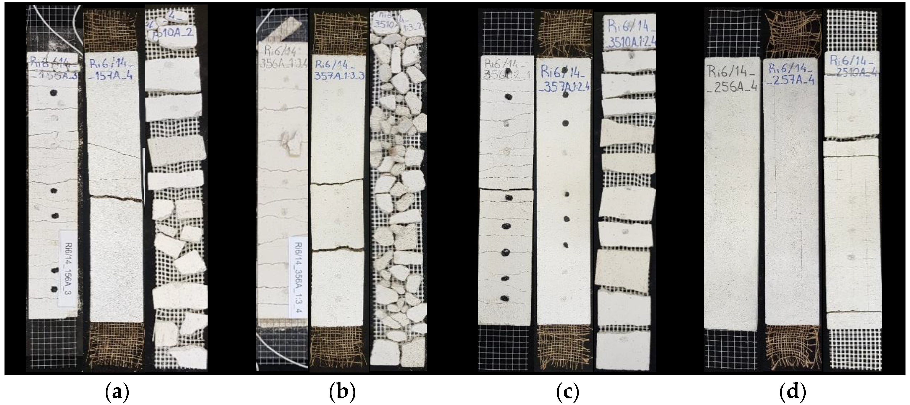
Table 2 shows the average value and standard deviation of the ultimate (maximum) stress, specific mass, and an estimate of the dynamic elastic modulus for each type of specimen (based on ultrasound tests). Figure 4 shows the typical rupture mechanisms for each group of specimens of reinforced renders (grouped by type of mortar).
2.4. Analysis of Results
The results obtained show that the value of the ultimate tensile stress is strongly dependent on the reinforcement mesh while the type of mortar does not seem to have a significant influence on these results. The values obtained for the ultimate tensile stress are quite consistent for each type of specimen since the standard deviation values are relatively low.
In addition to determining the ultimate tensile stress through tension tests, it was also possible to estimate the dynamic elastic modulus by the ultrasound method. These results confirm that the deformability of reinforced renders with Portland cement mortar is lower than that of lime mortar renders and that renders with hydrated lime mortar are the most deformable.
The rupture mechanisms obtained in the tensile tests are similar to those observed in similar tests in other research works [11,12,13,14,15]. It should also be pointed out that the occurrence of a certain rupture mechanism among those represented strongly depends on the shear stress installed at the ends of the specimen, as well as on the tensile performance of the mesh and the effectiveness of the connection between the reinforcing mesh and the mortar [16].
It was possible to observe that the specimens’ failure due to slipping of the mesh never occurred, which shows the efficacy of the connection between the mortar and these reinforcing meshes. However, in some of the reinforced mortars, the tensile strength of the mortar was inconveniently higher than that of the fiber mesh. In these cases, the mesh breaks soon after the first crack occurs without mobilizing again the tensile strength of the mortar and thus without promoting crack propagation. Such were the cases of renders with natural lime mortar at a 1/2 binder/sand ratio reinforced with jute fiber mesh or that of cement mortars, both with jute and metallic meshes.
Two types of reinforced renders were chosen to be applied to wallettes built for this purpose. In a first phase, the weaker types of mortar were excluded, namely the hydrated lime with 1/3 binder/sand ratio and natural hydraulic lime with 1/3 ratio. Among the renders with hydraulic lime at 1/2 binder/sand ratio, both steel and glass fiber mesh managed to mobilize the mortar strength and promote crack propagation. Among these two, the render with glass fiber mesh was chosen because it presented greater tensile strength. Regarding cement at 1/3 ratio, the choice was made on the glass fiber mesh, which was the only one that mobilized the cement mortar tensile strength.
3. Diagonal Compression Tests on Wallettes
3.1. Specimen Preparation
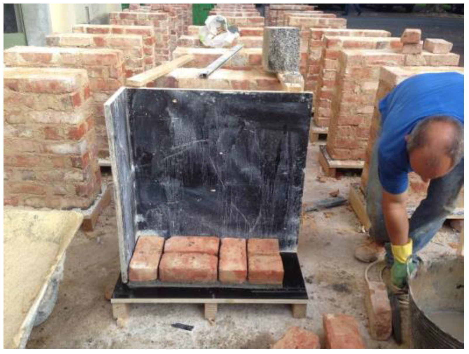
New small specimens of solid ceramic brick masonry, named wallettes, were produced, at 70 × 70 cm2, simulating the constitution and behavior of original wallettes (previously taken from a real building), which were previously characterized through an experimental campaign. The brick layout pattern is shown in Figure 5 (the wall thickness, of 21 cm, corresponds to the longest brick edge). Bricks obtained from the demolition of an old building (the same from which the other wallettes had been taken) were used, and previously characterized. The laying mortar used was composed of hydrated lime, a mixture of river and sandpit sand, half weight of each (with 1:3 binder/sand ratio), and water. The mortar constitution was equivalent to that of the old building from where the bricks were obtained. Three wallettes were selected, prepared, and instrumented to perform diagonal compression tests. The laying mortars underwent a curing process of approximately six months before the application of the reinforced render.
The M2M3 wallette was strengthened with a reinforced render consisting of a cement mortar with a 1/3 binder/sand ratio and a VIPLÁS 275 glass fiber mesh [17]. The M3M3 wallette was strengthened with a reinforced render consisting of natural hydraulic lime mortar with a 1/2 binder/sand ratio and a VIPLÁS 275 glass fiber mesh [17]. The M1M5 wallette, without any strengthening solution, was tested for comparison purposes.
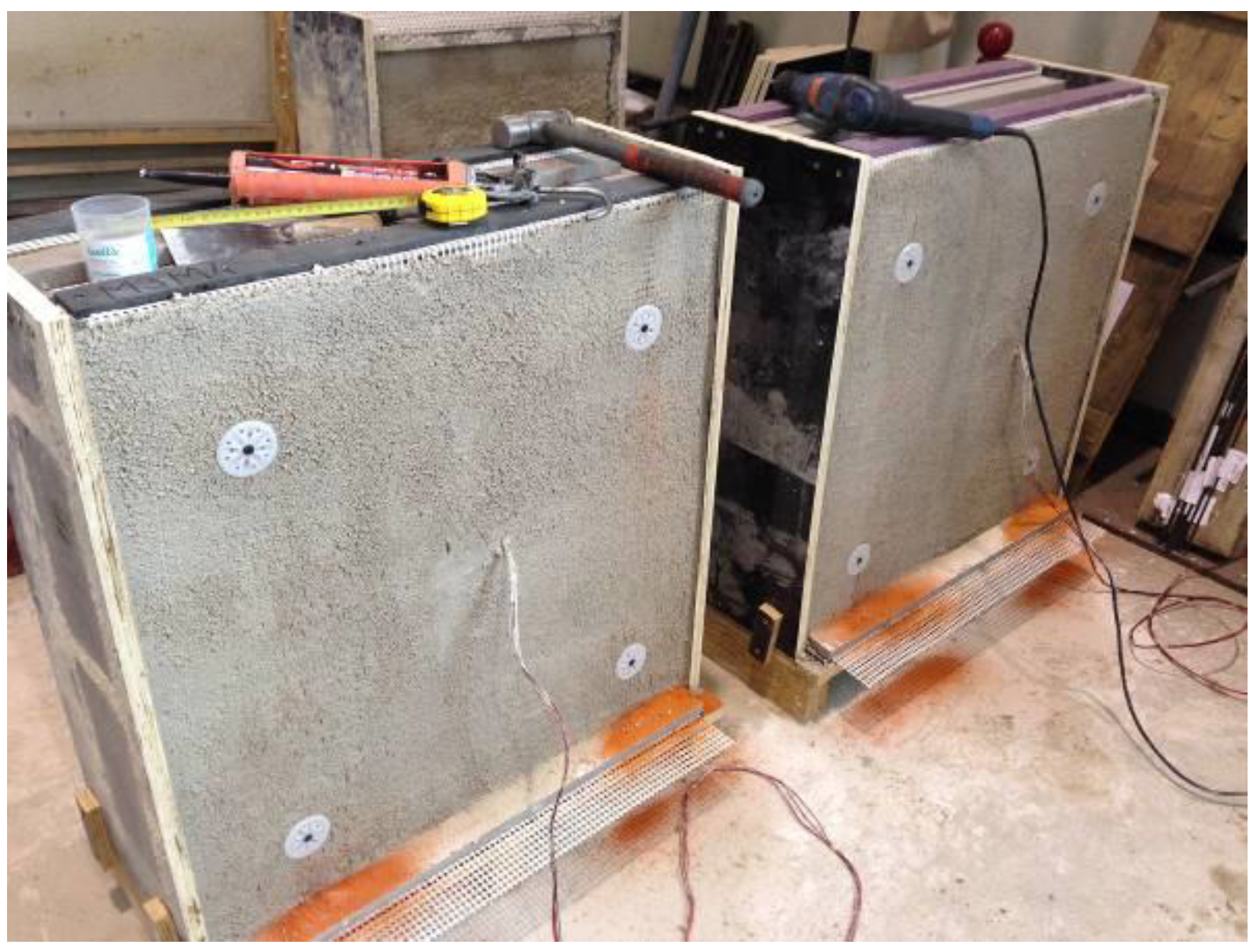
The reinforced renders were applied to both sides of the wallettes with a thickness of 3 cm (2 cm for the leveling layer + 1 cm for the finishing layer). A wooden structure was created around the wallettes to anchor the rendered mesh, so it remained stretched during the application and curing of the mortar. The mesh was affixed to the wallette through four plastic connectors, approximately 7 cm long, forming a 50 × 50 cm square centered on the wallette, as shown in Figure 6.
After approximately six months of curing the reinforced render mortar, the wallettes were subjected to diagonal compression tests.
3.2. Experimental Campaign
Diagonal compression tests were conducted in order to assess the in-plane distortional capacity of the wallettes when a shear action (such as during a seismic action) was applied. The standard testing method described in ASTM E519/E519M—10 standard [18] was followed with slight adaptations.
After placing each wallette in the correct position, it was instrumented with two displacement transducers of type W50 (50 mm course) on each face to measure the deformation in the horizontal and vertical directions.
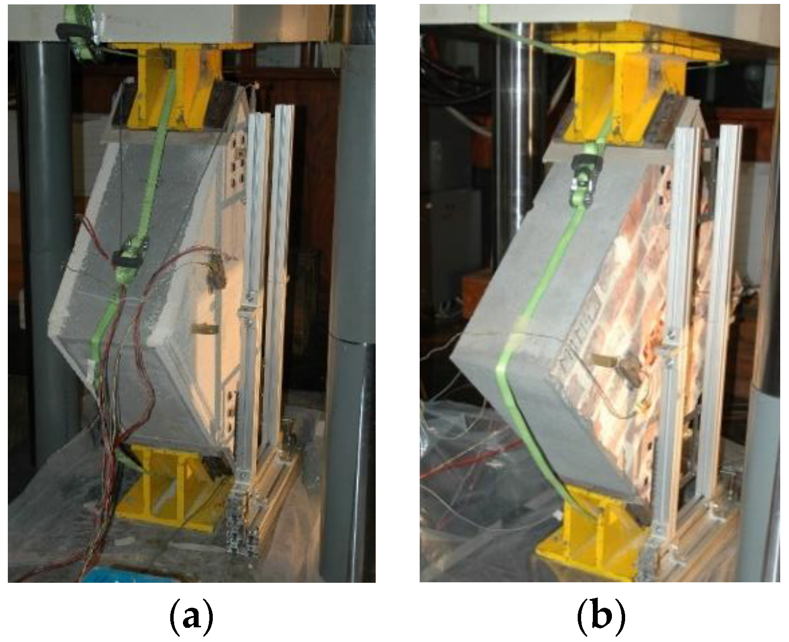
The test method basically consisted of gradually applying the load with a controlled speed of 0.005 mm/s, sampling the data at a 50 Hz. rate. Loading was performed vertically with the wallette positioned at 45 °C, as shown in Figure 7.
3.3. Results Obtained
3.4. Analysis of Results
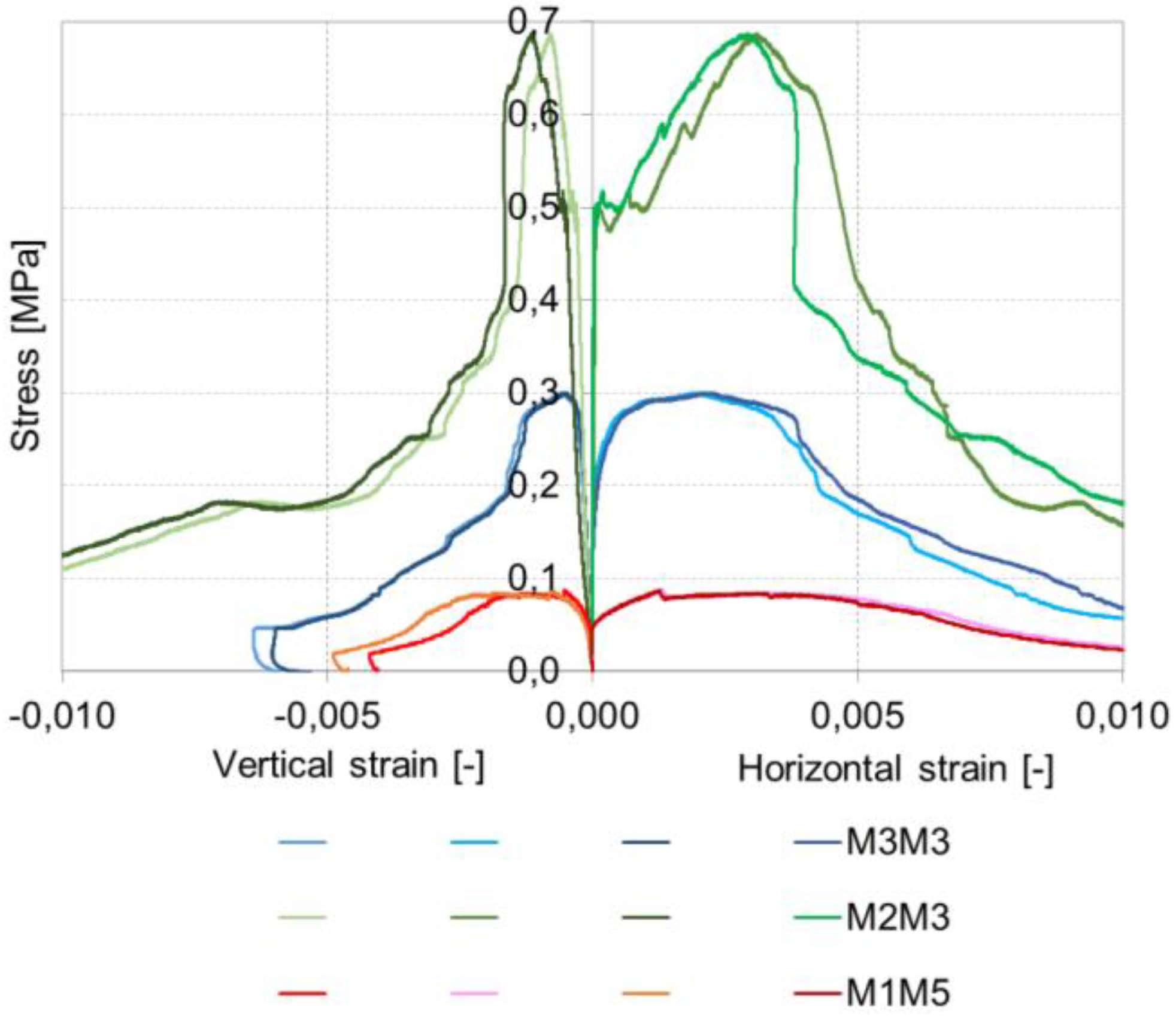
The maximum shear stresses obtained in the diagonal compression tests of the wallettes show that the bare brick masonry walls have a reduced shear strength and may need strengthening when horizontally loaded.
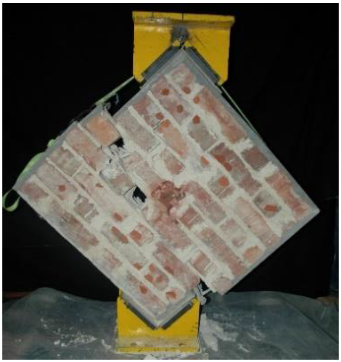
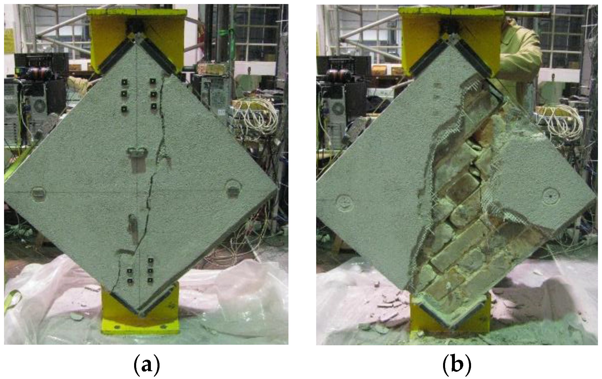
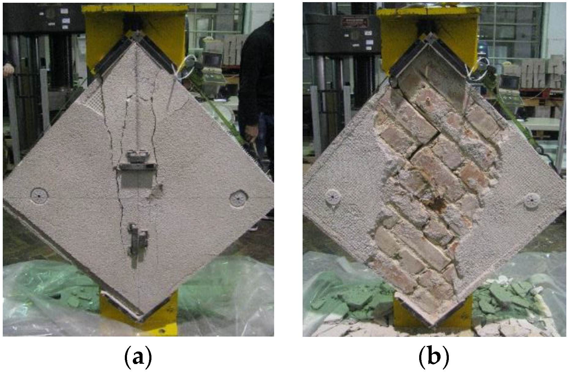
As seen in the images of the collapse mechanisms, the ruptures in both reinforced renders are associated with diagonal cracks (towards the opposite vertices of the wallettes), typical of shear collapse. The collapse mechanisms observed in the wall core are in accordance with those observed in the render, resulting in a main diagonal crack, zigzagging along the mortar joints, which is also typical of a shear collapse mode.
After the test, it was found that some zones of the render were not adhering to the wall, showing a lack of compatibility between the render and the brickwork. This effect was more significant for the cement mortar render.
Regarding the effectiveness of the strengthening solutions, both types of reinforced renders promoted an increase in strength compared to the unreinforced wall.
Reinforced render with natural hydraulic lime increased the shear strength by about 2.25 times while cement mortar reinforced render increased it by about 6.5 times. This significantly higher strength increase in the cement mortar render when compared to natural the hydraulic lime render shows that, besides the type of fiber (the fiber meshes were similar), the mortar properties also strongly influence the strengthening effect of the reinforced render solution.
4. Conclusions
Because the experimental campaign involved the testing of the reinforced renders alone, bare walls and reinforced walls, it allows for assessing the efficiency of the reinforced render as a strengthening technique for masonry walls subjected to diagonal compression.
The selected reinforced renders need to be adequate to be applied to resistant solid brick masonry walls to improve their shear / seismic behavior.
Considering that both strength- testing solutions ensure increased strength, two different types of objectives may be considered. If the type of strengthening to be made is more demanding in terms of material compatibility (with the reinforcement and the support) and consequent durability of the support where it will be inserted, the reinforced render solution composed of natural hydraulic lime mortar and glass fiber mesh is more suitable. If, on the other hand, the type of strengthening to be applied has to guarantee greater overall wall strength, then the most suitable reinforced render solution is composed of cement mortar and glass fiber mesh.
Author Contributions
Conceptualization, all authors; methodology, all authors; formal analysis, A.I.M.; resources, J.G.F., P.C. and M.d.R.V.; data curation, A.I.M.; writing—original draft preparation, A.I.M.; writing—review and editing, J.G.F., P.C. and M.d.R.V.; visualization, A.I.M.; supervision, all authors; project administration, J.G.F., P.C. and M.d.R.V.; funding acquisition, J.G.F., P.C. and M.d.R.V. All authors have read and agreed to the published version of the manuscript.
Funding
This work was developed as part of the Research and Innovation Project 2013–2020 of LNEC “REuSE—Coatings for Rehabilitation: Safety and Sustainability”. The work was also supported by the FCT—Fundação para a Ciência e a Tecnologia through the project reference PTDC/ECI EGC/30567/2017, entitled “RESIST-2020—Seismic Rehabilitation of Old Masonry-Concrete Buildings”. The authors also acknowledge Vimaplás, for supplying the glass fiber mesh, SECIL Argamassas, for the supply of cement and natural hydraulic lime and for the application of reinforced coatings, as well as the companies Lena Agregados, SA and Soarvamil—Sand Company of Vale de Milhaços, Lda., for the supply of sands.
Institutional Review Board Statement
Not applicable.
Informed Consent Statement
Not applicable.
Data Availability Statement
The data obtained in the tests may be supplied upon request.
Acknowledgments
The authors acknowledge the collaboration of the colleagues and technicians of LNEC for their help, availability, commitment, and knowledge.
Conflicts of Interest
The authors declare no conflict of interest.
References
- Ghiassi, B. Mechanics and durability of textile reinforced mortars: A review of recent advances and open issues. RILEM Tech. Lett. 2019, 4, 130–137. [Google Scholar] [CrossRef]
- Pederneiras, C.M.; Veiga, R.; Brito, J. Incorporation of Natural Fibres in Rendering Mortars for the Durability of Walls. Infrastructures 2021, 6, 82. [Google Scholar] [CrossRef]
- D’Ambrisi, A.; Feo, L.; Focacci, F. Experimental and analytical investigation on bond between Carbon-FRCM materials and masonry. Compos. Part B Eng. 2013, 46, 15–20. [Google Scholar] [CrossRef]
- Guerreiro, J.; Proença, J.; Gomes Ferreira, J.; Gago, A.S. Bonding and anchoring of a CFRP reinforced render for the external strengthening of old masonry buildings. Constr. Build. Mater. 2017, 155, 56–64. [Google Scholar] [CrossRef]
- Guerreiro, J.; Gomes Ferreira, J.; Gago, A.S.; Proença, J. Experimental and numerical analysis of the behaviour of masonry walls strengthened with CFRP reinforced render. Asian J. Civ. Eng. 2020, 21, 331–349. [Google Scholar] [CrossRef]
- Guerreiro, J.; Proença, J.; Gomes Ferreira, J.; Gago, A.S. Experimental characterization of in-plane behaviour of old masonry walls strengthened through the addition of CFRP reinforced render. Compos. Part B Eng. 2018, 148, 14–26. [Google Scholar] [CrossRef]
- Guerreiro, J.; Gomes Ferreira, J.; Proença, J.; Gago, A. Strengthening of old masonry walls for out-of-plane seismic loading with a CFRP reinforced render. Exp. Tech. 2018, 42, 355–369. [Google Scholar] [CrossRef]
- Balsamo, A.; Di Ludovico, M.; Prota, A.; Manfredi, G. Masonry walls strengthened with innovative composites. Am. Concr. Inst. 2011, 2, 769–786. [Google Scholar]
- Carozzi, F.; Milani, G.; Poggi, C. Mechanical properties and numerical modeling of Fabric Reinforced Cementitious Matrix (FRCM) systems for strengthening of masonry structures. Compos. Struct. 2014, 107, 711–725. [Google Scholar] [CrossRef]
- EN 1015-11; Methods of Test for Mortar for Masonry—Part 11: Determination of Flexural and Compressive Strength of Hardened Mortar. CEN: Brussels, Belgium, 1999.
- Carozzi, F.; Poggi, C. Mechanical properties and debonding strength of fabric reinforced cementitious matrix (FRCM) systems for masonry strengthening. Compos. Part B 2015, 70, 215–230. [Google Scholar] [CrossRef]
- Donnini, J.; Corinaldesi, V.; Nanni, A. Mechanical properties of FRCM using carbon fabrics with different coating treatments. Compos. Part B 2016, 88, 220–228. [Google Scholar] [CrossRef]
- Ascione, L.; De Felice, G.; De Santis, S. A qualification method for externally bonded fibre reinforced cementitious matrix (FRCM) strengthening systems. Compos. Part B 2015, 78, 497–506. [Google Scholar] [CrossRef]
- De Santis, S.; De Felice, G. Tensile behavior of mortar-based composites for externally bonded reinforcement systems. Compos. Part B 2015, 68, 401–413. [Google Scholar] [CrossRef]
- Arboleda, D.; Carozzi, F.; Nanni, A.; Poggi, C. Testing procedures for the uniaxial tensile characterization of fabric-reinforced cementitious matrix composites. ASCE J. Compos. Constr. 2015, 20, 04015063. [Google Scholar] [CrossRef]
- Caggegi, C.; Carozzi, F.; De Santis, S.; Fabbrocino, F.; Focacci, F.; Hojdys, L. Experimental analysis on tensile and bond properties of PBO and Aramid fabric reinforced cementitious matrix for strengthening masonry structures. Compos. Part B 2017, 127, 175–195. [Google Scholar] [CrossRef]
- National Laboratory of Civil Engineering. VIPLÁS 167 e VIPLÁS 275—Redes para Reforço de Revestimentos de Paredes (para Aplicação em ETICS); Documento de Homologação de novos materiais e processos de construção DH942, July 2017; National Laboratory of Civil Engineering: Lisbon, Portugal, 2017. [Google Scholar]
- ASTM E519/E519M–10; Standard Test Method for Diagonal Tension (Shear) in Masonry Assemblages. ASTM-American Society for Testing and Materials: West Conshohocken, PA, USA, 2010.
Figure 1.
Reinforced render specimens: execution (a) and curing (b).

Figure 2.
Execution of the tensile tests on reinforced mortar specimens.

Figure 3.
Load vs. Time diagrams obtained for reinforced renders with mortar of natural hydraulic lime with 1/2 binder/sand ratio: (a) steel mesh, (b) jute fiber mesh, and (c) glass fiber mesh.
Figure 3.
Load vs. Time diagrams obtained for reinforced renders with mortar of natural hydraulic lime with 1/2 binder/sand ratio: (a) steel mesh, (b) jute fiber mesh, and (c) glass fiber mesh.

Figure 4.
Rupture mechanisms for each type of reinforced render with different mortar binder and different type of mesh (steel, jute, glass fiber, in this order from left to right in each group). (a) Hydrated lime. (b) Natural hydraulic lime 1/3 Binder/Sand ratio. (c) Natural hydraulic lime 1/2 binder/sand ratio. (d) Portland cement.

Figure 5.
Execution of new solid brick wallettes.

Figure 6.
Wallettes with the reinforced render.

Figure 7.
Diagonal compression test of strengthened (a) and plain (b) wallettes.

Figure 8.
Collapse mode of the plain (non-strengthened) wallette M1M5.

Figure 9.
Collapse mode of wallette M2M3 (with cement mortar reinforced render) at the render (a) and at the wall core (b).
Figure 9.
Collapse mode of wallette M2M3 (with cement mortar reinforced render) at the render (a) and at the wall core (b).

Figure 10.
Collapse mode of wallette M3M3 (with NHL mortar reinforced render) at the render (a) and at the wall core (b).
Figure 10.
Collapse mode of wallette M3M3 (with NHL mortar reinforced render) at the render (a) and at the wall core (b).

Figure 11.
Stress-strain diagram for the wallettes.


Table 1.
Identification and composition of the reinforced mortar specimens.
| Specimens Group Identification | Render Mortar | Reinforcing Mesh | |
|---|---|---|---|
| Binder Type | Binder/Sand Ratio | ||
| AL_1:3_S | Hydrated (air) lime | 1:3 | Steel |
| AL_1:3_J | Jute | ||
| AL_1:3_G | Glass | ||
| HL_1:3_S | Natural hydraulic lime | 1:3 | Steel |
| HL_1:3_J | Jute | ||
| HL_1:3_G | Glass | ||
| HL_1:2_S | Natural hydraulic lime | 1:2 | Steel |
| HL_1:2_J | Jute | ||
| HL_1:2_G | Glass | ||
| PC_1:3_S | Portland cement | 1:3 | Steel |
| PC_1:3_J | Jute | ||
| PC_1:3_G | Glass | ||
Table 2.
Average values (and standard deviations) obtained in the tests on reinforced renders.
| Specimens Group | Ultimate Tensile Stress (MPa) | Specific Mass (kg/m3) | Dynamic Elastic Modulus (MPa) |
|---|---|---|---|
| AL_1:3_S | 405 (11) | 1812 (218) | 2148 (270) |
| AL_1:3_J | 42 (5) | 1684 (38) | 1921 (86) |
| AL_1:3_G | 550 (82) | 1697 (20) | 1843 (85) |
| HL_1:3_S | 404 (19) | 1913 (11) | 4284 (212) |
| HL_1:3_J | 35 (1) | 1721 (24) | 4810 (74) |
| HL_1:3_G | 600 (26) | 1742 (17) | 4562 (339) |
| HL_1:2_S | 392 (7) | 1805 (39) | 8056 (469) |
| HL_1:2_J | 39 (4) | 1855 (34) | 8379 (225) |
| HL_1:2_G | 580 (38) | 1834 (30) | 7785 (354) |
| PC_1:3_S | 423 (9) | 1968 (13) | 14,439 (401) |
| PC_1:3_J | 38 (2) | 1821 (57) | 11,561 (997) |
| PC_1:3_G | 578 (11) | 1889 (18) | 13,622 (376) |
Table 3.
Parameters obtained from the diagonal compression tests.
| Wallette | Shear Strength (MPa) | Max. Distortion (mm/mm) | Shear Modulus (MPa) | Rupture Energy (J) |
|---|---|---|---|---|
| M1M5 | 0.09 | 1.95 × 10⁻³ | 44.77 | 54.02 |
| M2M3 | 0.69 | 2.56 × 10⁻³ | 268.69 | 1140.07 |
| M3M3 | 0.30 | 1.81 × 10⁻³ | 165.72 | 327.85 |
Publisher’s Note: MDPI stays neutral with regard to jurisdictional claims in published maps and institutional affiliations. |
© 2022 by the authors. Licensee MDPI, Basel, Switzerland. This article is an open access article distributed under the terms and conditions of the Creative Commons Attribution (CC BY) license (https://creativecommons.org/licenses/by/4.0/).
Share and Cite
MDPI and ACS Style
Marques, A.I.; Ferreira, J.G.; Candeias, P.; Veiga, M.d.R. Experimental Evaluation of Brick Masonry Walls Strengthened with TRM (Textile Reinforced Mortar) Renders. Buildings 2022, 12, 840. https://doi.org/10.3390/buildings12060840
AMA Style
Marques AI, Ferreira JG, Candeias P, Veiga MdR. Experimental Evaluation of Brick Masonry Walls Strengthened with TRM (Textile Reinforced Mortar) Renders. Buildings. 2022; 12(6):840. https://doi.org/10.3390/buildings12060840
Chicago/Turabian StyleMarques, Ana Isabel, João Gomes Ferreira, Paulo Candeias, and Maria do Rosário Veiga. 2022. "Experimental Evaluation of Brick Masonry Walls Strengthened with TRM (Textile Reinforced Mortar) Renders" Buildings 12, no. 6: 840. https://doi.org/10.3390/buildings12060840
Note that from the first issue of 2016, this journal uses article numbers instead of page numbers. See further details here.