


Swelling Behavior and Flow Rates of a Novel Hydrophilic Gasket Used in Composite Geomembrane Vertical Cutoff Walls and Infrastructures Exposed to Contaminated Groundwater

Abstract
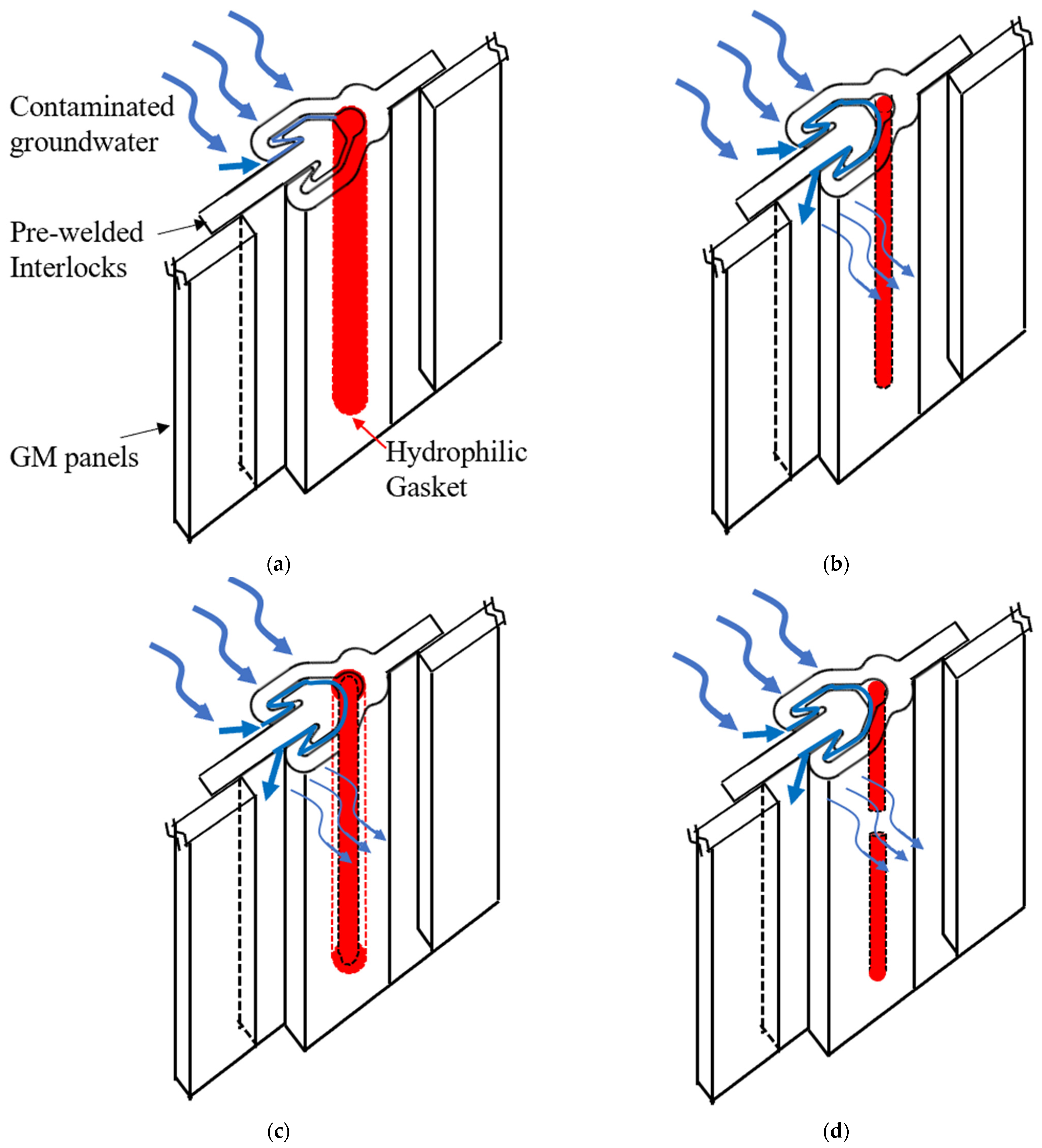
:1. Introduction
2. Materials and Methods
2.1. Materials
2.2. Testing Liquids
2.3. Testing Meathods and Apparatus
2.3.1. Swelling Tests
- Free swelling tests.
- 2.
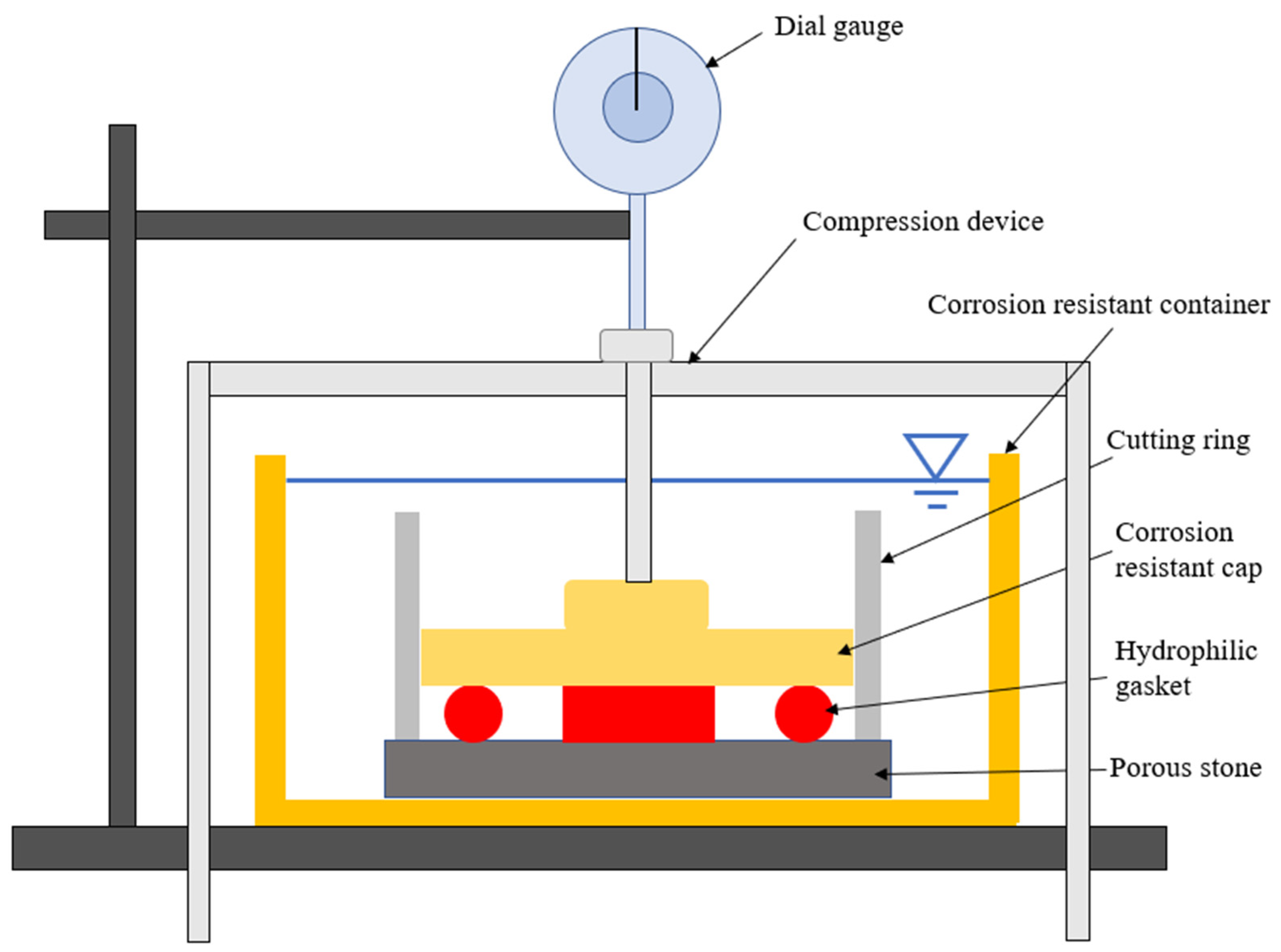
- Radial swelling tests.
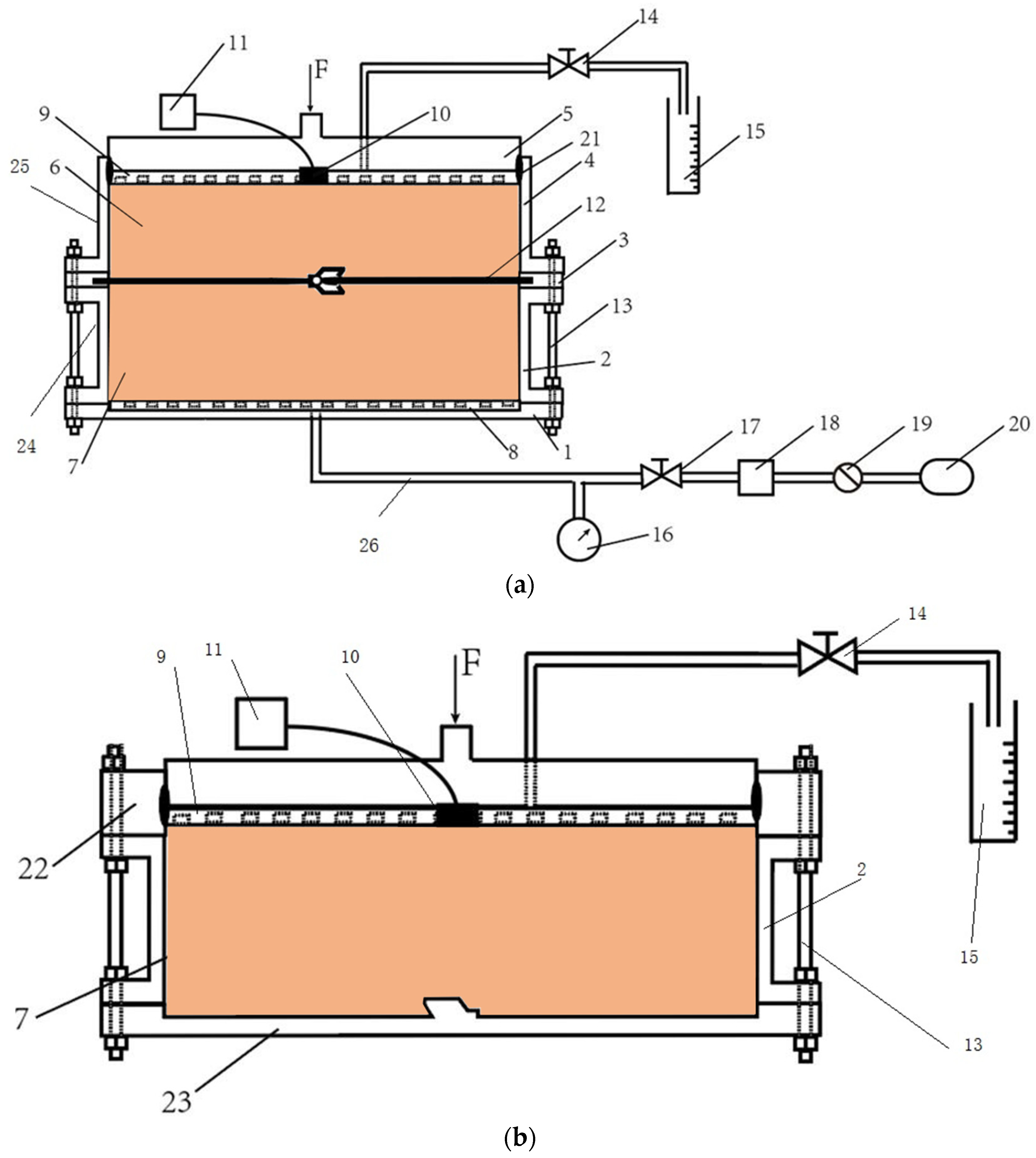
2.3.2. Flow Rates Model Tests and Apparatus
2.3.3. Scanning Electron Microscope (SEM) Tests
3. Results and Discussion
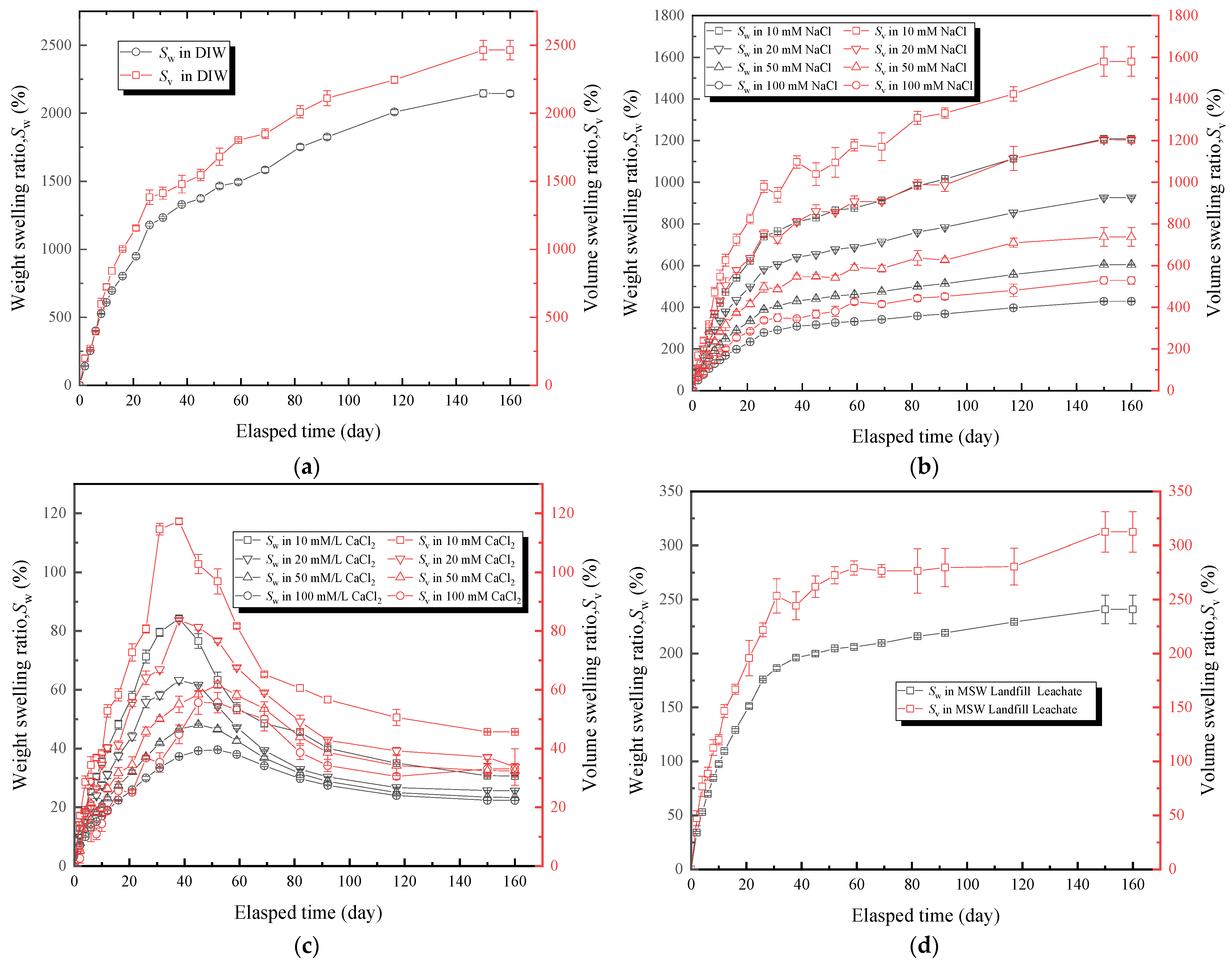
3.1. Free Swelling Tests Results
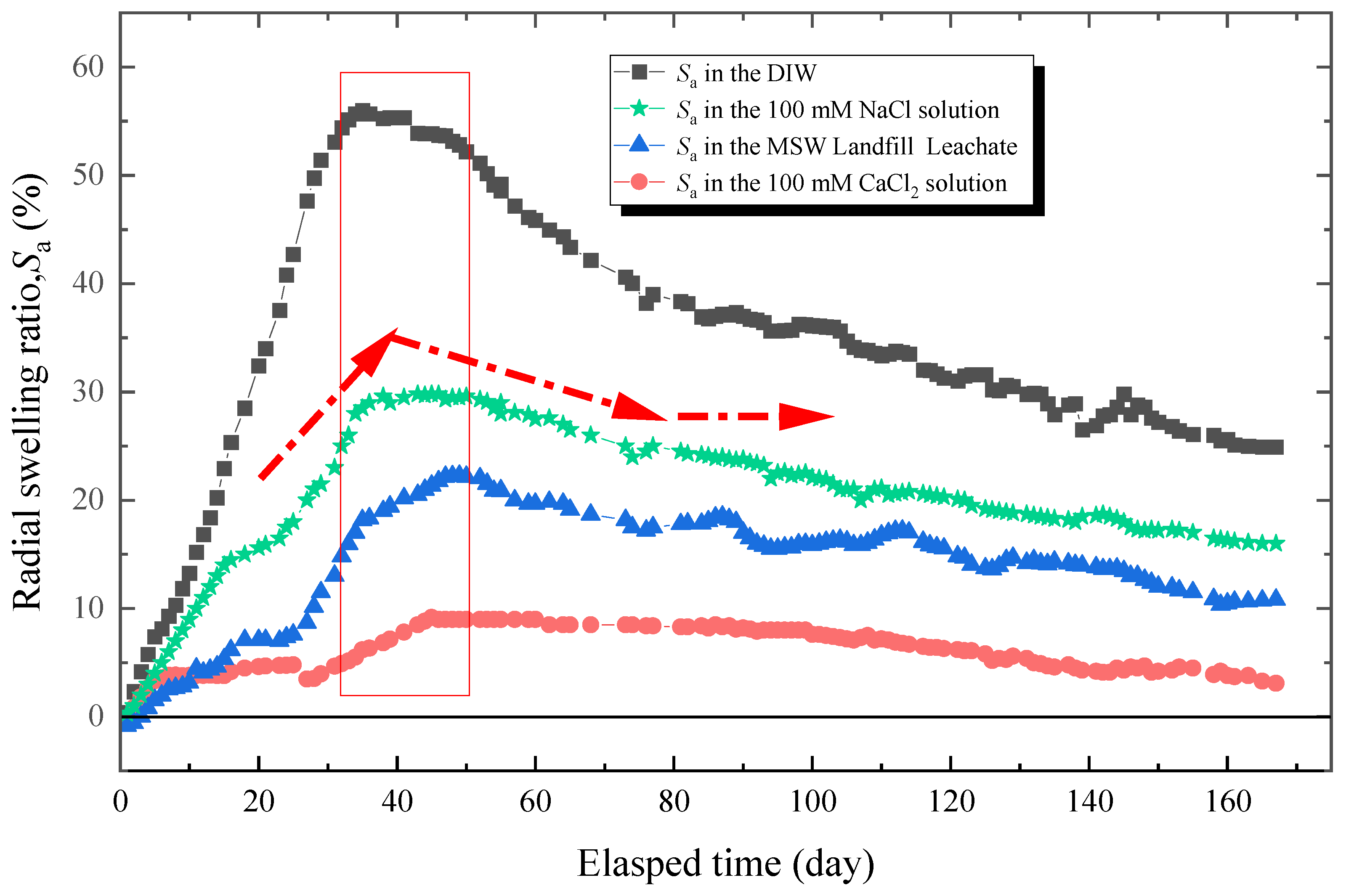
3.2. Radial Swelling Tests Results
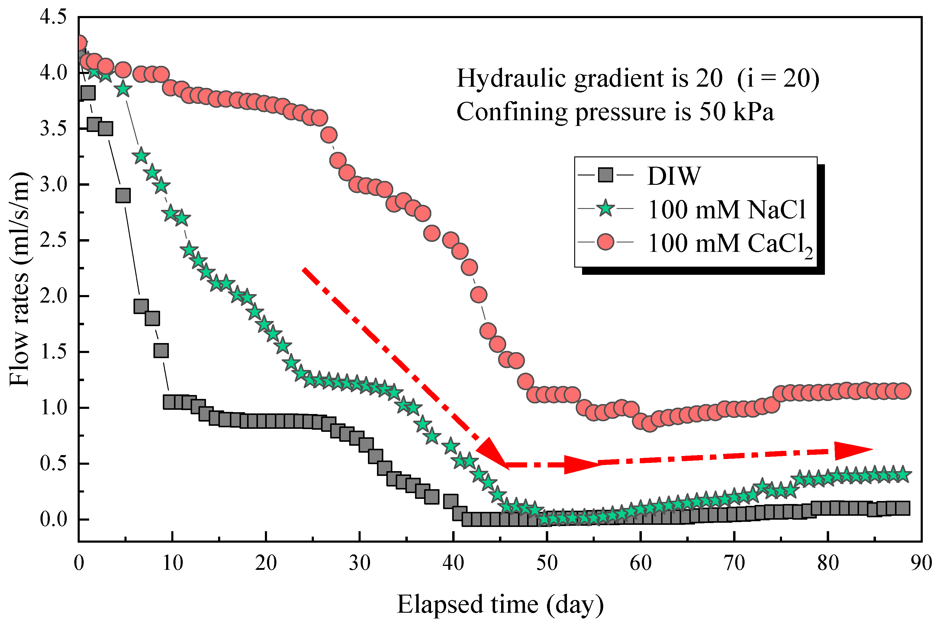
3.3. Flow Rates Tests Results
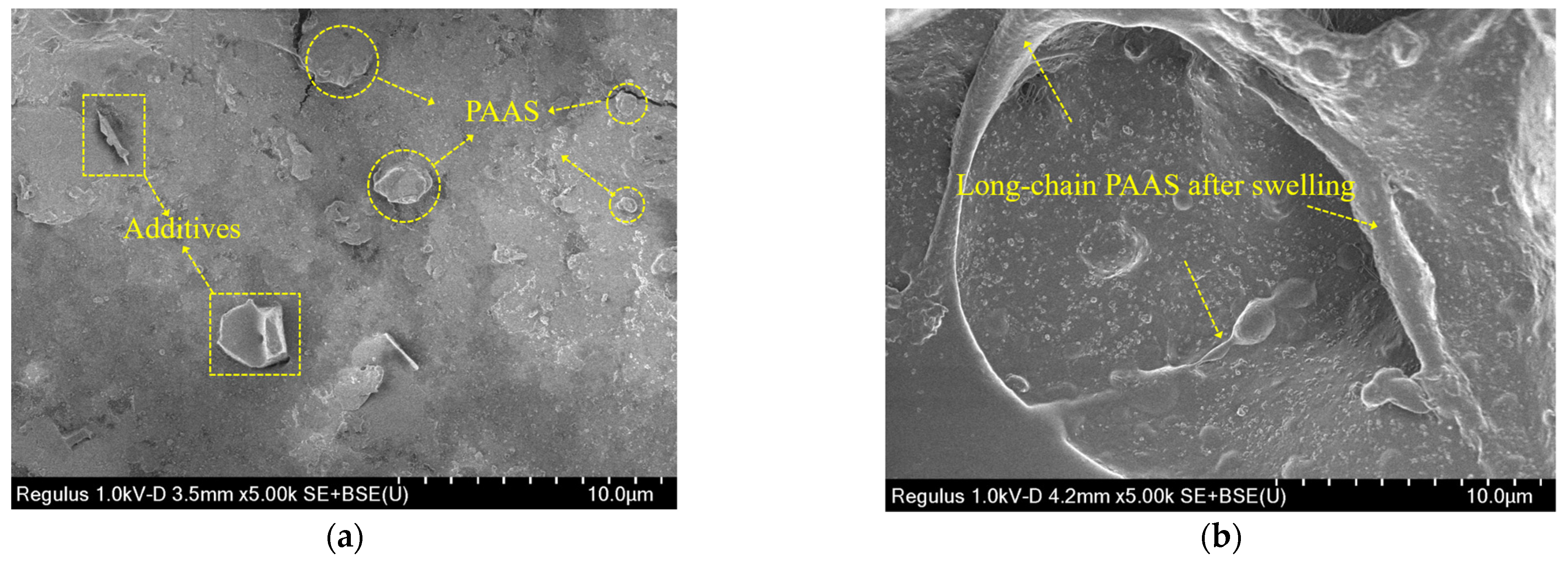
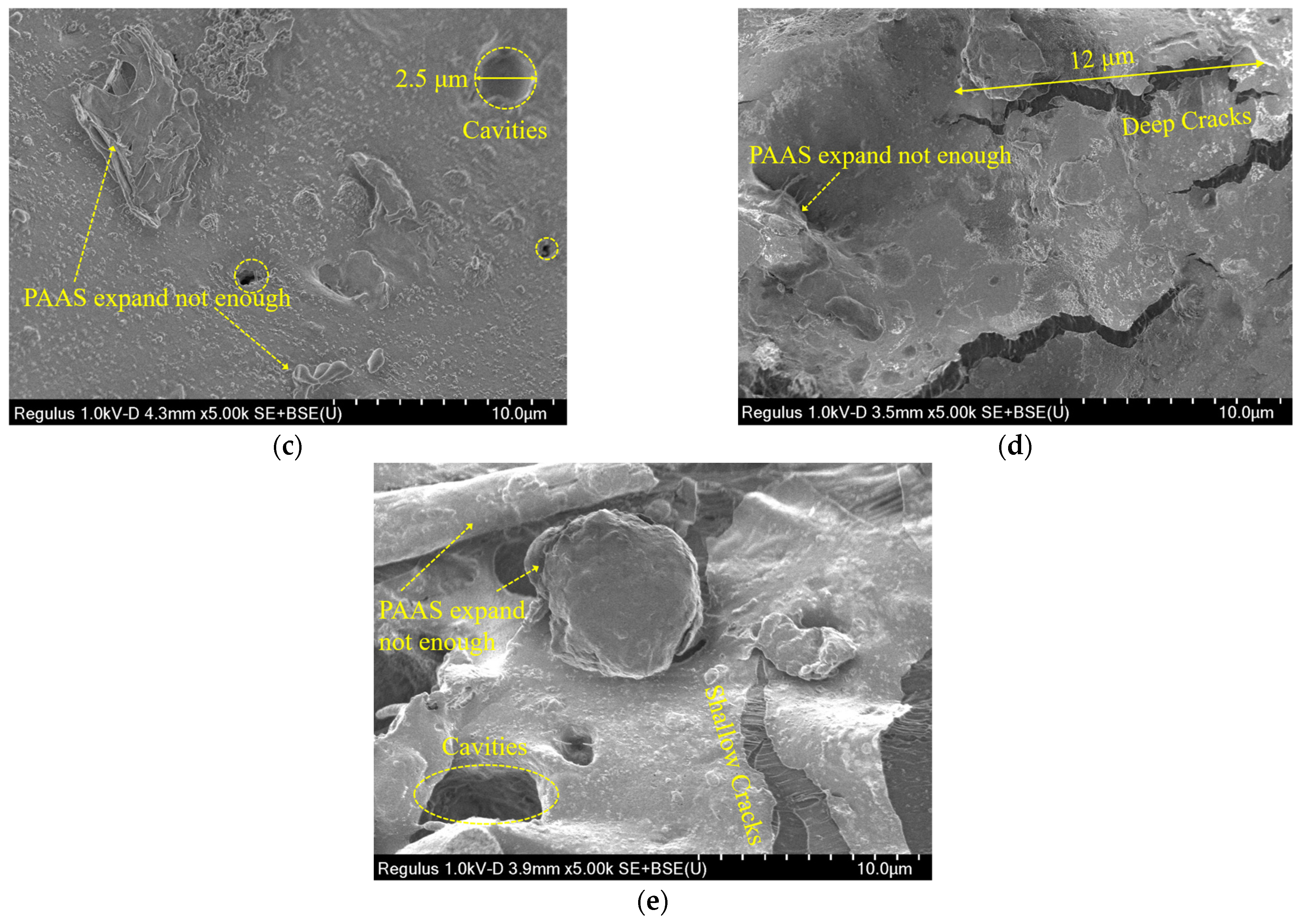
3.4. Scanning Electron Microscope (SEM) Tests Results
4. Conclusions
- The Sw and Sv of the hydrophilic gasket material soaked in the DIW were the highest, followed by NaCl solutions, MSW landfill leachates, and CaCl2 solutions. The Sw and Sv curves of specimens immersed in CaCl2 solutions increased in the initial stage, then decreased until a stable state. The results illustrated that the ionic strength and multivalent cations greatly impacted the swelling behavior of hydrophilic gaskets.
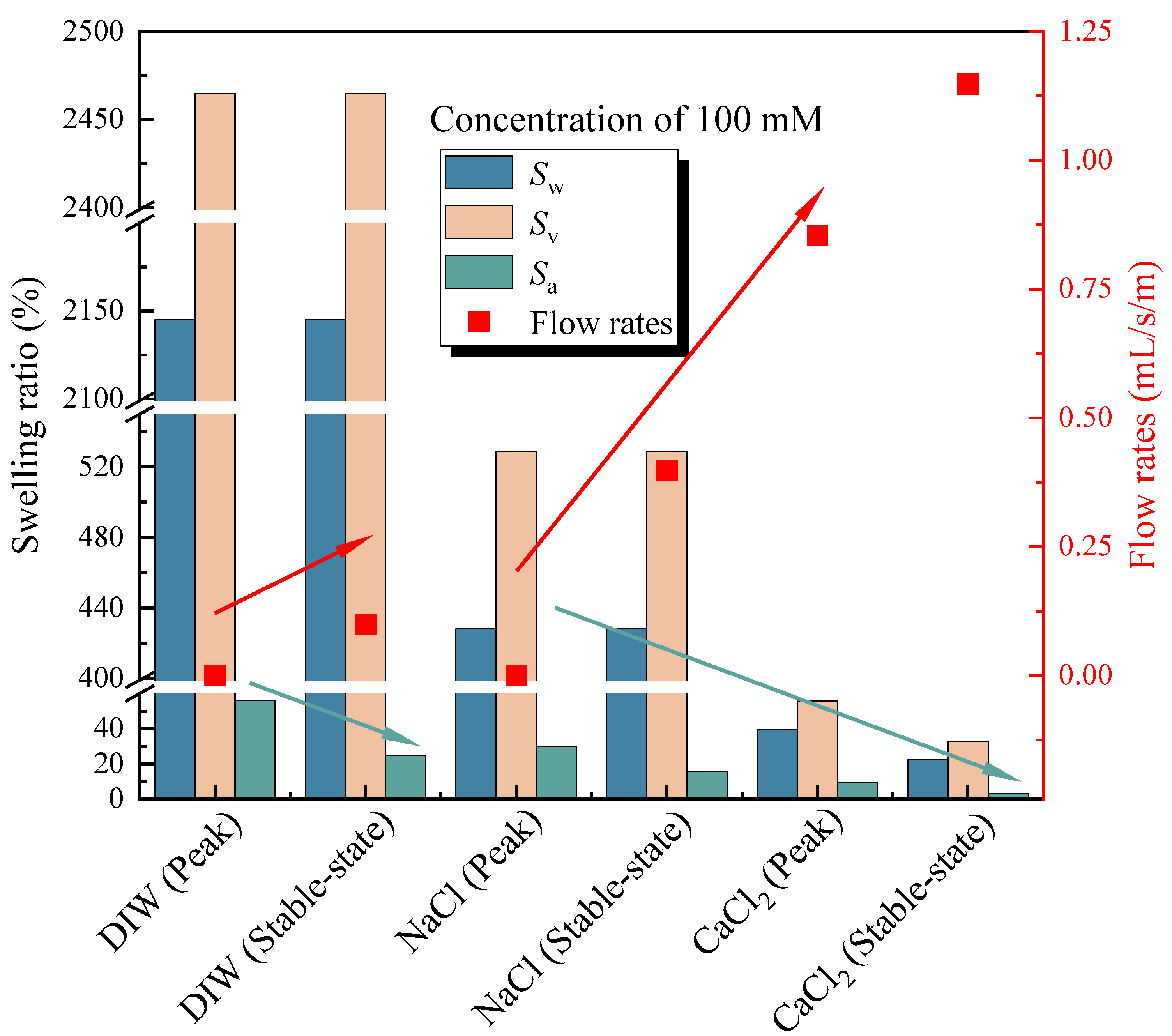
- For specimens tested in the DIW, the NaCl solution (100 mM), the CaCl2 solution (100 mM), and MSW landfill leachates, the Sa was 56, 29.8, 9.2, 22.3% at peak and 25, 16, 3.3, 10.7% in a stable state, and the relaxation ratio was 55, 46, 64, 52%, respectively.
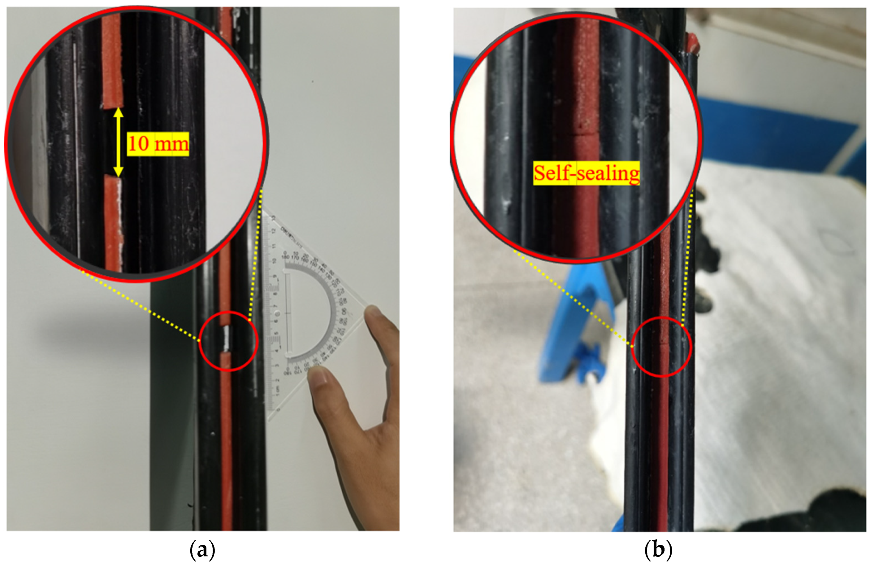
- The self-healing of the hydrophilic gasket was observed. The flow rates of specimens penetrated with DIW, NaCl, and CaCl2 decreased to a stable state, which was 0, 0, 0.855 mL/s/m, respectively, then increased extremely slowly to the stable values of 0.099, 0.399, and 1.148 mL/s/m, respectively. The flow rates of the hydrophilic gasket penetrated with the DIW were the lowest, followed by the NaCl solution (100 mM), and the CaCl2 solution (100 mM), which was attributed to the effect of the multivalent ionic strength on the swelling capacity of the hydrophilic gasket.
- The SEM images showed that there was a lot of long-chain expanded PAAS, the matrix immersed in DIW could be propped up and expanded to a large volume. However, there were numerous microcracks or microcavities on the surface of specimens immersed in the CaCl2 solution (100 mM) and the MSW landfill leachates. This explained the results of the difference of the free swelling ratio of hydrophilic gaskets immersed in different solutions. The micro-morphology indicated that the SAP with insufficient expansion could separate from the matrix under the high multivalent ionic strength.
Author Contributions
Funding
Data Availability Statement
Conflicts of Interest
References
- Fu, X.L.; Shen, S.Q.; Reddy, K.R.; Yang, Y.L.; Du, Y.J. Hydraulic conductivity of sand/biopolymer-amended bentonite backfills in vertical cutoff walls permeated with lead solutions. J. Geotech. Geoenviron. Eng. 2022, 148, 04021186. [Google Scholar] [CrossRef]
- Fu, X.L.; Zhang, R.; Reddy, K.R.; Li, Y.C.; Yang, Y.L.; Du, Y.J. Membrane behavior and diffusion properties of sand/SHMP-amended bentonite vertical cutoff wall backfill exposed to lead contamination. Eng. Geol. 2021, 284, 106037. [Google Scholar] [CrossRef]
- Du, Y.J.; Fan, R.D.; Liu, S.Y.; Reddy, K.R.; Jin, F. Workability, compressibility and hydraulic conductivity of zeolite-amended clayey soil/calcium-bentonite backfills for slurry-trench cutoff walls. Eng. Geol. 2015, 195, 258–268. [Google Scholar] [CrossRef]
- Du, Y.J.; Fan, R.D.; Reddy, K.R.; Liu, S.Y.; Yang, Y.L. Impacts of presence of lead contamination in clayey soil–calcium bentonite cutoff wall backfills. Appl. Clay Sci. 2015, 108, 111–122. [Google Scholar] [CrossRef]
- Lee, T.; Benson, C.H. Flow past bench-scale vertical ground-water cutoff walls. J. Geotech. Geoenviron. Eng. 2000, 126, 511–520. [Google Scholar] [CrossRef]
- Peng, C.H.; Feng, S.J.; Chen, H.X.; Ding, X.H. An analytical model for one-dimensional diffusion of degradable contaminant through a composite geomembrane cut-off wall. J. Contam. Hydrol. 2021, 242, 103845. [Google Scholar] [CrossRef]
- Thomas, R.W.; Koerner, R.M. Advances in HDPE barrier walls. Geotext. Geomembranes 1996, 14, 393–408. [Google Scholar] [CrossRef]
- Liu, L.; Liu, Y.; Zhen, S.; Ding, S.; Jin, J.; Wang, Y.; Ge, Y. Applications of Geomembrane Cutoff Walls in Remediation of Contaminated Sites. In Proceedings of the 8th International Congress on Environmental Geotechnics Volume 2: Towards a Sustainable Geoenvironment, Singapore, 11 October 2018; Springer: Berlin/Heidelberg, Germany, 2018; p. 335. [Google Scholar]
- Kavazanjian, E., Jr.; Dixon, N.; Katsumi, T.; Kortegast, A.; Legg, P.; Zanzinger, H. Geosynthetic barriers for environmental protection at landfills. In Proceedings of the Geosynthetics-8th International Conference on Geosynthetics, Yokohama, Japan, 18–22 September 2006; pp. 121–152. [Google Scholar]
- Peng, C.H.; Feng, S.J.; Zheng, Q.T.; Ding, X.H.; Chen, Z.L.; Chen, H.X. A two-dimensional analytical solution for organic contaminant diffusion through a composite geomembrane cut-off wall and an aquifer. Comput. Geotech. 2020, 119, 103361. [Google Scholar] [CrossRef]
- Tachavises, C.; Benson, C.H. Hydraulic Importance of Defects in Vertical Groundwater Cut-Off Walls. In Proceedings of the In Situ Remediation of the Geoenvironment, Minneapolis, MN, USA, 5–8 October 1997; Evans, J.C., Ed.; American Society of Civil Engineers: Reston, VA, USA, 1997; pp. 168–180. [Google Scholar]
- Qian, X.; Zheng, Z.; Guo, Z.; Qi, C.; Liu, L.; Liu, Y.; Ge, Y. Applications of geomembrane cutoff walls in remediation of contaminated sites. In The International Congress on Environmental Geotechnics; Springer: Singapore, 2018; pp. 335–342. [Google Scholar]
- Koerner, R.M.; Guglielmetti, J.L. Vertical barriers: Geomembranes, assessment of barrier containment technologies, a comprehensive treatment for environmental remediation applications. In Proceedings of the International Containment Technology Workshop, Baltimore, MD, USA, 29–31 August 1995; Rumer, R.R., Mitchell, J.K., Eds.; pp. 95–118. [Google Scholar]
- Zhen, S.; Huo, C.; He, Z.; Zheng, Z.; Zheng, F.; Sun, X.; Liu, L. Application and comparative study of vertical barrier technology. Environ. Sanit. Eng. 2017, 25, 51–56. [Google Scholar]
- Bouazza, A.; Zornberg, J.G.; Adam, D. Geosynthetics in Waste Containment Facilities: Recent Advances. State-of-the-Art keynote paper. In Proceedings of the Seventh International Conference on Geosynthetics, Nice, France, 22–27 September 2002; Balkema, A.A., Ed.; Volume 2, pp. 445–510. [Google Scholar]
- Daniel, D.E.; Koerner, R.M. On the use of geomembranes in vertical barriers. In Proceedings of the Advances in Transportation and Geoenvironmental Systems Using Geosynthetics, Denver, CO, USA, 5–8 August 2000; pp. 81–93. [Google Scholar]
- Yang, C.; Shen, S.L.; Hou, D.W.; Liao, S.M.; Yuan, D.J. Material properties of the seal gasket for shield tunnels: A review. Constr. Build. Mater. 2018, 191, 877–890. [Google Scholar] [CrossRef]
- Dehbari, N.; Tang, Y. Water swellable rubber composites: An update review from preparation to properties. J. Appl. Polym. Sci. 2015, 132, 42786. [Google Scholar] [CrossRef]
- Wang, G.; Li, M.; Chen, X. Preparation and water-absorbent properties of a water-swellable rubber. J. Appl. Polym. Sci. 1998, 68, 1219–1225. [Google Scholar] [CrossRef]
- Park, J.H.; Kim, D. Preparation and characterization of water-swellable natural rubbers. J. Appl. Polym. Sci. 2001, 80, 115–121. [Google Scholar] [CrossRef]
- Ren, W.T.; Zhang, Y.; Peng, Z.L.; Zhang, Y.X. Investigation on the water-swelling properties of chlorinated polyethylene modified by in situ formed sodium acrylate. Polym. Test. 2004, 23, 809–816. [Google Scholar] [CrossRef]
- Lang, F.; Li, S.; Du, F.; Wang, Z. Mechanical, Water-swelling, and Morphological Properties of Water-swellable Thermoplastic Vulcanizates Based on Polyvinyl Chloride/Crosslinked Sodium Polyacrylate/Chlorinated Polyethylene Blends. J. Macromol. Sci. B 2013, 52, 1322–1340. [Google Scholar] [CrossRef]
- Zhang, Z.; Zhang, G.; Li, D.; Liu, Z.; Chen, X. Chlorohydrin water-swellable rubber compatibilized by an amphiphilic graft copolymer. II. Effects of PVA-g-PBA and CPA on water-swelling behaviors. J. Appl. Polym. Sci. 1999, 74, 3145–3152. [Google Scholar] [CrossRef]
- Zhang, Z.; Zhang, G.; Wang, C.; Liu, D.; Liu, Z.; Chen, X. Chlorohydrin water-swellable rubber compatibilized by an amphiphilic graft copolymer. III. Effects of PEG and PSA on water-swelling behavior. J. Appl. Polym. Sci. 2001, 79, 2509–2516. [Google Scholar] [CrossRef]
- Sae-oui, P.; Sirisinha, C.; Thepsuwan, U. Dependence of mechanical and aging properties of chloroprene rubber on silica and ethylene thiourea loadings. Eur. Polym. J. 2007, 43, 185–193. [Google Scholar] [CrossRef]
- Nakason, C.; Nakaramontri, Y.; Kaesaman, A.; Kangwansukpamonkon, W.; Kiatkamjornwong, S. Synthesis and characterization of water swellable natural rubber vulcanizates. Eur. Polym. J. 2013, 49, 1098–1110. [Google Scholar] [CrossRef]
- Zohuriaan-Mehr, M.J.; Kabiri, K. Superabsorbent Polymer Materials: A Review. Iranian Polymer J. 2008, 17, 451–477. [Google Scholar]
- Tan, J.S.; Shen, S.L.; Zhou, A.; Wang, Z.N.; Lyu, H.M. Laboratory evaluation of long-term sealing behaviors of two water-swelling materials for shield tunnel gasket. Constr. Build. Mater. 2020, 249, 118711. [Google Scholar] [CrossRef]
- Polgar, L.M.; Fallani, F.; Cuijpers, J.; Raffa, P.; Broekhuis, A.A.; van Duin, M.; Picchioni, F. Water-swellable elastomers: Synthesis, properties and applications. Rev. Chem. Eng. 2018, 35, 45–72. [Google Scholar] [CrossRef]
- You, K.M.; Park, S.S.; Lee, C.S.; Kim, J.M.; Park, G.P.; Kim, W.N. Preparation and characterization of conductive carbon nanotube-polyurethane foam composites. J. Mater. Sci. 2011, 46, 6850–6855. [Google Scholar] [CrossRef]
- Liu, C.; Ding, J.; Zhou, L.; Chen, S. Mechanical properties, water-swelling behavior, and morphology of water-swellable rubber prepared using crosslinked sodium polyacrylate. J. Appl. Polym. Sci. 2006, 102, 1489–1496. [Google Scholar] [CrossRef]
- Ayres, E.; Oréfice, R.L.; Yoshida, M.I. Phase morphology of hydrolysable polyurethanes derived from aqueous dispersions. Eur. Polym. J. 2007, 43, 3510–3521. [Google Scholar] [CrossRef]
- Brown, R.P. Natural Ageing of Rubber—Changes in Physical Properties over 40 Years; iSmithers Rapra Publishing: Shawbury, UK, 2000. [Google Scholar]
- Kömmling, A.; Jaunich, M.; Pourmand, P.; Wolff, D.; Gedde, U.W. Influence of Ageing on Sealability of Elastomeric O-Rings. Macromol. Symp. 2017, 373, 1600157. [Google Scholar] [CrossRef]
- Kömmling, A.; Jaunich, M.; Wolff, D. Effects of heterogeneous aging in compressed HNBR and EPDM O-ring seals. Polym. Degrad. Stab. 2016, 126, 39–46. [Google Scholar] [CrossRef]
- Kömmling, A.; Jaunich, M.; Wolff, D. Revealing effects of chain scission during ageing of EPDM rubber using relaxation and recovery experiment. Polym. Test. 2016, 56, 261–268. [Google Scholar] [CrossRef]
- Cortlever, N.G. Geolock, Plastic HDPE-Liner for Vertical Cut-Off Barriers around Landfill; Geotechnics Holland: Amsterdam, The Netherlands, 1995. [Google Scholar]
- Manassero, M.; Pasqualini, E. Ground polluant containment barriers. In Proceedings of the Mediterranean Conference on Environmental Geotechnology, Cesme, Turkey, 25–27 May 1992; pp. 195–204. [Google Scholar]
- Manassero, M.; Fratalocchi, E.; Pasqualini, E.; Spanna, C.; Verga, F. Containment with vertical cutoff walls. In Geoenvironment 2000: Characterization, Containment, Remediation, and Performance in Environmental Geotechnics; ASCE: Reston, VA, USA, 1995; pp. 1142–1172. [Google Scholar]
- ASTM D698; Standard Test Methods for Laboratory Compaction Characteristics of Soil Using Standard Effort (12,400 ft-lbf/ft3 (600 kN-m/m3)). ASTM: West Conshohocken, PA, USA, 2012.
- ASTM D2487; Standard Practice for Classification of Soils for Engineering Purposes (Unified Soil Classification System). ASTM: West Conshohocken, PA, USA, 2018.
- Yang, Y.L.; You, X.Y.; Chen, J.N.; Fu, X.L.; Du, Y.J. Hydraulic conductivity of novel geosynthetic clay liner to bauxite liquor from China: Modified fluid loss test evaluation. J. Environ. Manag. 2022, 316, 115208. [Google Scholar] [CrossRef]
- ASTM E70; Standard Test Method for pH of Aqueous Solutions with the Glass Electrode. ASTM: West Conshohocken, PA, USA, 2015.
- ASTM D1125; Standard Test Method for Electrical Conductivity and Resistivity of Water. ASTM: West Conshohocken, PA, USA, 2014.
- ASTM D3616; Standard Test Method for Rubber—Determination of Gel, Swelling Index, and Dilute Solution Viscosity. ASTM: West Conshohocken, PA, USA, 2014.
- ASTM C143; Standard Test Method for Slump of Hydraulic Cement Concrete. ASTM: West Conshohocken, PA, USA, 2015.
- Petr, H.; Zdenka, V.; Petr, D. Water-swellable rubbers containing powdery poly(acrylamide) hydrogel. Macromol. Mater. Eng. 1997, 245, 203. [Google Scholar]
- Wang, Z.N.; Shen, S.L.; Zhou, A.; Lyu, H.M. Experimental investigation of water-swelling characteristics of polymer materials for tunnel sealing gasket. Constr. Build. Mater. 2020, 256, 119473. [Google Scholar] [CrossRef]
- Liao, S.Q.; Lin, H.J.; She, X.D.; Liao, J.H. Research and preparation of curing water-swelling natural rubber. Spec. Purpose Rubber Prod. 2009, 30, 5–8. (In Chinese) [Google Scholar]
- Lee, W.F.; Wu, R.J. Superabsorbent polymeric materials. I. Swelling behaviors of crosslinked poly (sodium acrylate-co-hydroxyethyl methacrylate) in aqueous salt solution. J. Appl. Polym. Sci. 1996, 62, 1099–1114. [Google Scholar] [CrossRef]
- Liu, J.C.; Duan, Y.S. Preparation and properties of water swellable water-swelling polyurethane elastomer. China Elastomerics 2010, 20, 9–12. (In Chinese) [Google Scholar]
- Ma, J.; Wang, T.W. Preparation and characterization of water-absorbing water-swelling polyurethane foam composites with microsized sodium polyacrylate particles. J. Appl. Polym. Sci. 2018, 135, 46702. [Google Scholar] [CrossRef]


| Title 1 Chemical | Mass Content (%) |
|---|---|
| Chlorinated polyethylene (CPE) | 42.5 |
| SiO2 | 17 |
| Chlorinated paraffin | 12 |
| Sodium polyacrylate (PAAS) | 12 |
| Palmitic acid | 8.5 |
| Stearic acid | 4.5 |
| Dicumyl peroxide (DCP) | 2.5 |
| Color agent | 1 |
| Property | Details |
|---|---|
| Sodium (mg/L) | 860 |
| Calcium (mg/L) | 128 |
| Magnesium (mg/L) | 39.3 |
| Iron (mg/L) | 6.62 |
| Aluminum (mg/L) | 2.16 |
| Copper (mg/L) | 0.0247 |
| Nickel (mg/L) | 0.486 |
| Zinc (mg/L) | 0.246 |
| Cadmium (mg/L) | 0.00016 |
| Manganese (mg/L) | 0.0207 |
| Chromium (mg/L) | 5.77 |
| Lead (mg/L) | 0.0162 |
| Arsenic (mg/L) | 0.104 |
| Sulfate (mg/L) | 254 |
| Ammonia nitrogen (mg/L) | 2160 |
| Total nitrogen, TN (mg/L) | 2240 |
| Total phosphorus, TP (mg/L) | 28.5 |
| Chemical Oxygen Demand (CODcr), (mg/L) | 5450 |
| Biological Oxygen Demand (BOD5), (mg/L) | 1400.3 |
| Ionic strength, I (mM) | 63.18 |
| RMD (mM1/2) | 9.01 |
| Testing Liquids | Target Concentration (mM) | Measured Concentration (mM) | EC at 25 °C (mS/cm) | pH | Ionic Strength, I (mM) |
|---|---|---|---|---|---|
| DIW | N/A | N/A | 0.00134 | 6.91 | 0 |
| NaCl solution | 10 | 10.10 | 1.228 | 7.03 | 5.05 |
| 20 | 19.95 | 2.35 | 6.9 | 9.98 | |
| 50 | 50.12 | 5.72 | 6.67 | 25.06 | |
| 100 | 99.95 | 10.73 | 6.54 | 49.98 | |
| CaCl2 solution | 10 | 9.90 | 2.28 | 7.72 | 19.8 |
| 20 | 20.10 | 4.3 | 7.43 | 40.2 | |
| 50 | 50.10 | 9.9 | 7.19 | 100.2 | |
| 100 | 100.10 | 18.94 | 7.02 | 200.2 | |
| MSW landfill leachates | N/A | N/A | 35.4 | 8.48 | 63.18 |
Publisher’s Note: MDPI stays neutral with regard to jurisdictional claims in published maps and institutional affiliations. |
© 2022 by the authors. Licensee MDPI, Basel, Switzerland. This article is an open access article distributed under the terms and conditions of the Creative Commons Attribution (CC BY) license (https://creativecommons.org/licenses/by/4.0/).
Share and Cite
Wang, M.; Fu, X.; Jiang, Z.; Che, C.; Jiang, N.; Du, Y. Swelling Behavior and Flow Rates of a Novel Hydrophilic Gasket Used in Composite Geomembrane Vertical Cutoff Walls and Infrastructures Exposed to Contaminated Groundwater. Buildings 2022, 12, 2207. https://doi.org/10.3390/buildings12122207
Wang M, Fu X, Jiang Z, Che C, Jiang N, Du Y. Swelling Behavior and Flow Rates of a Novel Hydrophilic Gasket Used in Composite Geomembrane Vertical Cutoff Walls and Infrastructures Exposed to Contaminated Groundwater. Buildings. 2022; 12(12):2207. https://doi.org/10.3390/buildings12122207
Chicago/Turabian StyleWang, Min, Xianlei Fu, Zheyuan Jiang, Chi Che, Ningjun Jiang, and Yanjun Du. 2022. "Swelling Behavior and Flow Rates of a Novel Hydrophilic Gasket Used in Composite Geomembrane Vertical Cutoff Walls and Infrastructures Exposed to Contaminated Groundwater" Buildings 12, no. 12: 2207. https://doi.org/10.3390/buildings12122207