Article

Real-Time and Remote Construction Progress Monitoring with a Quadruped Robot Using Augmented Reality

1
Myers-Lawson School of Construction, Virginia Tech, Blacksburg, VA 24061, USA
2
Procon Consulting, Arlington, VA 22201, USA
*
Author to whom correspondence should be addressed.
Buildings 2022, 12(11), 2027; https://doi.org/10.3390/buildings12112027
Submission received: 7 October 2022 / Revised: 5 November 2022 / Accepted: 16 November 2022 / Published: 19 November 2022

Abstract

:
Construction progress monitoring involves a set of inspection tasks with repetitive in-person observations on the site. The current manual inspection process in construction is time-consuming, inefficient and inconsistent mainly due to human limitations in the ability to persistently and accurately walkthrough the job site and observe the as-built status of which robots are considerably better. Enabling the process of visual inspection with a real-time and remote inspection capability using robots can provide more frequent and accessible construction progress data for inspectors to improve the quality of inspection and monitoring. Also, integrating remote inspection with an Augmented Reality (AR) platform can help the inspector to verify as-planned BIM data with the as-built status. This paper proposes a new approach to perform remote monitoring of the construction progress in real-time using a quadruped robot and an AR solution. The proposed computational framework in this study uses a cloud-based solution to integrate the quadruped robot’s control for remote navigation through the construction site with 360° live-stream video of the construction status, as well as a real-time AR solution to visualize and compare the as-built status with as-planned BIM geometry. The implementation of the proposed framework is discussed, and the developed framework is evaluated in two use cases through experimental investigations.

1. Introduction

Construction progress monitoring is an essential task in the construction process. Current construction progress monitoring requires an inspector to walk through the job site regularly and visually compare the as-built progress with the as-planned requirement of the project [1], which also involves capturing visual evidence of the as-built construction status. However, such manual inspection is unsystematic and inefficient and sometimes creates rework due to miscommunications [2,3]. Automating the data collection process in progress monitoring can significantly affect the management of the project [4], prevent schedule delays and cost overruns, and improve the overall quality of construction work [1]. Importantly, real-time monitoring of construction projects is the key to keep pace with the construction progress and reduce rework [5]. However, frequent monitoring of construction projects requires significant time, manpower, data management, and travel to multiple job sites [5]. Remote inspection, sometimes referred to as e-inspection, enables easier access to real-time and more accurate information [6].
The construction industry has witnessed a growing interest in adopting visualization techniques including virtual/mixed/augmented reality (VR/MR/AR) [7,8]. AR enables visualizing additional information (e.g., the BIM model) over reality through an intermediary device (e.g., mobile devices or head-mounted displays) that provides additional information on the surrounding environment and facilitates construction progress monitoring [7]. AR is defined by the International Organization of Standardization (ISO) in their standard ISO 18039:2019 as a “type of mixed reality system in which virtual world data are embedded and/or registered with the representation of physical world data.” The effectiveness and usefulness of AR has been studied in many applications in construction, including safety monitoring [9], structural health monitoring [8], and progress monitoring [1]. However, these AR applications require manual and time-consuming physical visits on the job site [5]. Telepresence AR or remote AR brings the real-life view to a remote user and has been used for providing training and education in construction [10]. Telepresence AR differs from VR in that the user perceives and observes real-life objects as opposed to virtual objects in VR [11].
Ground robots and aerial robots or unmanned aerial vehicles (UAVs) can be used to assist the human experts to collect visual data from the site [12]. Robots are unmanned mechanical equipment that can perform different automation tasks in either teleoperation mode or autonomous mode [13]. In teleoperation mode, robots are remotely operated in real-time and have little to no autonomy in navigation. On the other hand, autonomous robots require minimal high-level instructions to make many low-level decisions on their own either by using rule-based logic or through machine learning-based predictive reasoning. In this study, only remote robot teleoperation is considered.
This study integrates robotics and augmented reality in a cloud-based framework to facilitate remote construction progress monitoring. The role of the robot is to provide remote assistance to a remote human inspector by providing real-time visual data from the construction site. Augmented reality is used to provide both the as-built job site progress and the project’s as-planned BIM model clearly and intuitively. The BIM data used in this study is primarily focused on the geometry, colors, and textures extracted from the project’s BIM model. The use of other BIM data than geometry, colors, and textures in the AR view is not in the scope of this research. This study proposes an integration framework for two technologies (AR and quadruped robotics) in construction, a system architecture and an implementation strategy for the proposed framework. The objectives of the study are:
1
To design an integration framework for AR and quadruped robotics.
2
To develop a system architecture for remote control of the robot and visualization of the augmented site reality.
3
To evaluate the feasibility of the proposed framework.
In Section 2, the paper provides a background review. Section 4 explains the proposed framework in detail. The implementation approach of the proposed framework and evaluation procedure through prototype development and two case studies are explained in Section 5. The findings and practical implications of the study are discussed in Section 6. The limitations of the current study and recommendations for future work is explained in Section 7. Finally, Section 8 provides a summary of the study contributions.

2. Background

2.1. Progress Monitoring in Construction

Project management teams in construction need timely and accurate information of the project and its progress with respect to the original budget, deadlines, quality specifications, and safety requirements [3]. Construction projects are planned and managed by diverse teams, known as project stakeholders, often geographically distributed [14]. Technology plays an important role in bridging the gap between different project stakeholders through remote collaboration [15]. Kopsida et al. [16] identified construction progress monitoring tasks as data acquisition, information retrieval, progress estimation, and visualization. Various studies have attempted to automate each of these progress monitoring sub-tasks. For example, laser scanning [17] and spherical imaging [18] have been used to collect visual and geometric information of a site for the data acquisition stage. Recently, ground robots [19], as well as aerial robots [20], were used as data acquisition agents. The information retrieval task in construction progress monitoring involves extracting meaningful information from raw data. Laser scanning and photogrammetry techniques have been used for this purpose [21,22,23]. Other methods for information retrieval include computer vision that uses machine learning (ML) for object detection [24]. Retrieving information from site images that are noisy and cluttered is nonetheless a challenging task [16]. Simple image processing techniques without the use of ML that compare the shape, size, color, and texture of elements from 2D images have also been proposed [24]. However, these techniques have lower accuracy because of the many variations in elements, differences between the model and actual component, and lack of distinguishable textures in the many indoor components [16]. For progress estimation, as-built status is compared with as-planned models and documents to identify completed work or the percentage completion of construction work [16]. The point-to-point comparison method that compares individual points in the scans of the site and BIM model to detect the presence or absence of an element has been used [4,17,25]. This method is based on a probabilistic approach and cannot be applied to tasks like painting and tiling that does not produce large 3D elements [16]. Visualization of the progress monitoring results is also an important stage. Due to the lack of a systematic way of recording and presenting progress information, about 77% of the time in review meetings is spent on communicating the problem, leaving less time to evaluate the problem and brainstorm solutions [16].
Virtual reality [26] and augmented reality [27] provide efficient and intuitive solutions for the visualization and communication of project information. A major challenge with augmented reality is the correct and consistent alignment of the artificial content with the real-life view [16]. Meanwhile, virtual reality that does not overlay artificial content on real content but provides more immersive experience suffers from hardware limitations as current hardware in the market suffer from low resolution and cause discomfort for users from long duration operations [28]. While augmented reality solutions can be implemented using simple handheld smartphone or tablet computers, virtual reality solutions require specialized hardware. Mixed reality has also been used for this purpose, allowing interaction with virtual content anchored to real-life visuals [29]. Visualization techniques like AR, VR, and MR, often grouped together as extended reality (XR), provide immersive and intuitive experiences that promote comprehension of the project conditions [5]. It can also facilitate remote inspection as discussed in the next subsection.

Remote Inspection

Inspection plays an important role in construction progress monitoring. Conventionally, inspections are conducted by experienced inspectors physically visiting the project job site and visually observing the construction work under progress to identify any potential deviations from the original project plans [30]. When the inspectors cannot visit the construction site in-person, remote inspection can provide information on the job site to the inspector [31]. Remote inspection can provide a more efficient alternative to conventional inspection and can save human and capital resources [32]. Remote inspection can also be used when the inspection location is a hazardous area for the inspector to reach in-person [33]. In construction, remote inspection has been used to inspect tall structures or bridges using drones [30].
Remote inspection has been facilitated by a network of fixed cameras [33] or images collected by drones [34]. However, images from scattered points-of-view put a high level of mental load on the inspector to visualize and analyze the scene from multiple images [35]. Linn et al. [36] used immersive virtual reality to perform remote inspection of manufacturing processes and plants using 360° visual live stream. Immersive virtual reality provides a remote inspector with the experience of being on-site at the inspection location without the additional time and cost of travel involved [36]. However, previous approaches either used only real images (without added information to facilitate inspection) or performed inspection asynchronously (not in real-time). The challenge with previous approaches is that (a) a large amount of data needs to be stored in the form of videos and images, (b) raw images or videos do not provide additional information needed for progress monitoring (e.g., dimensions), the inspector has to refer to multiple construction documents and images to analyze the work, and (c) inspectors do not have access to the job site information in real-time and are supposed to wait until the next reality data collection is performed to access updated job site information.

2.2. Augmented Reality (AR) in Construction Progress Monitoring

The use of augmented reality (AR) and mixed reality (MR) technologies in the architecture, engineering, and construction (AEC) industry has been increasingly gaining traction due to improved hardware and software and an increased level of affordability to end-users. Different applications of AR have spanned different areas including safety [37], planning and simulation [38], communication and collaboration [39], education and training [40], and assembly [41].
An AR-based hazard warning system was implemented through wearable AR glasses [37]. AR glasses have also been used to address planning errors, productivity, and decision-making by visualizing construction activities, exploring different alternatives, and making adjustments and modifications when required [39,42,43]. In the area of communication and collaboration, AR/MR technologies have been used by some studies to allow for remote collaboration, visualization, and interaction between geographically remote and dispersed users to enhance the decision-making process [44,45]. Applications of AR/MR in education and training have been widely investigated and implemented. This includes training in construction trades, safety, and construction equipment operation [40,46,47,48]. The use of AR/MR glasses for assembly tasks has been reviewed and implemented by different researchers to reduce time, error, and task-loads while increasing the productivity of practitioners [49,50].
Some researchers have implemented AR/MR into their processes for addressing different aspects of construction progress monitoring. For example, Bae et al. [51] and Yeh et al. [52] reported on work by various researchers using AR/MR wearable devices to enable users to access and capture information for storage in their devices during walkthroughs on construction job sites. Ali et al. [5] proposed iVR, a near real-time inspection system that integrates 3D scanning, extended reality, and visual programming for the inspection of indoor construction activities. Their system enables remote inspection through the point clouds collected while providing access to feedback from inspection through augmented reality glasses in the field. Halder and Afsari [28] proposed a methodology for performing real-time remote inspection in an immersive environment using a legged robot deployed on a construction site. Hatem and Maula [53] created a 4D BIM model covering different stages of the construction process and used AR for visualizing and monitoring those stages. Kopsida and Brilakis [54] developed a system that performs an automatic real-time comparison between as-planned and as-built data by comparing the 3D data with spatial surface meshes on the Microsoft HoloLens. Their developed system enables progress monitoring by identifying elements in reality based on the plans. Lin et al. [27] developed a real-time 4D AR system to compare as-designed models with as-builts using AR glasses. Their developed system compares the position of the entities, sequence of the assembly tasks, and task dates for monitoring the construction progress of modular construction. Zaher et al. [55] integrated different tools including Primavera for schedules, Navisworks for 5D simulation, and Fusion tables for collecting, storing, sharing, and visualizing data to develop their two applications. Their first application, “BIM-U”, is an Android application that enables users to first update progress information on-site. The BIM-U application can be used to acquire an actual start, actual finish, progress percentage complete, and work breakdown structure (WBS) code and then transfer the information to a Fusion table to update the actual and budgeted cost. Their second application, “BIM-Phase”, is a mobile AR used to check the progress and status of projects with respect to time and cost by integrating a 4D as-planned model with as-built augmented videos. Soman and Whyte [56] monitored construction progress by creating an automated bidirectional flow of real-time information between the construction site and office. The 3D models created in BIM can be visualized through the AR-enabled devices on construction sites and the same devices can be used to scan the space, create a 3D mesh of the space, and convert that to an as-built model in the cloud.
Omar and Nehdi [57] examined variously automated and electronic construction data collection technologies including AR. They indicated that construction progress can be monitored using the overlaid 4D BIM model on the as-built, and as a result, defects can be identified to be addressed by decision-makers. Kwon et al. [58] developed two management systems for the inspection of the reinforced concrete defects. Their first system performed an image-matching for quality inspection in the office while their second system identified the errors in dimensions and omissions in the field. Zollmann et al. [59] proposed an approach for automatic progress monitoring using aerial 3-D reconstruction, and they used AR for visualizing progress and as-planned information on-site. Golparvar-Fard et al. [1] proposed D4AR, which provides integrated as-built and as-planned visualization, performs automated and remote construction progress monitoring, and identifies deviations. Shin and Dunston [60] evaluated the benefits of performing steel column inspection with a prototype AR system compared to a conventional method. Their results indicate that faster inspection results can be achieved using AR, although it is still less accurate.
The extensive work on AR conducted by many studies mentioned above indicate the potential of using AR for enhancing the efficiency and quality of construction progress monitoring. However, past studies used AR by either physically being at the inspection location with an AR device or manually augmenting collected images with virtual content. In this study, this motivated the development of an AR-based framework for progress monitoring enabled by quadruped robots that provide on-demand real-time information without additional travel cost or human resources.

2.3. Robotic Inspection and Monitoring

Construction inspection and control methods are mainly based on in-person observations and manual data collection, which is slow and expensive [61]. Project managers spend a significant amount of time in solving problems at a site arising due to late or inaccurate information [61,62]. Traditional practices of construction inspection are labor-intensive because the inspector spends time extracting information from drawings and plans and compares them with the as-built conditions [63,64]. As a result, inspections are carried out too infrequently to allow prompt corrective actions to be taken [63,65]. Construction inspection typically involves one or many inspectors physically walking through the construction site and visually inspecting the construction activities and/or work products [62]. Owners, architects, structural engineers, and many other stakeholders are responsible for multiple projects at a given time and they might not be frequently present at one project throughout the project life-cycle. Traveling from one site to another costs time and money that adds to the project overhead. The increasing complexity of construction projects warrants more frequent inspection and monitoring that cannot be supported by manual data collection [17]. The opportunity for real-time and remote inspection can provide more frequent and accessible inspection and monitoring of the job site to project stakeholders and ultimately prevent cost overruns, rework, and delays in construction projects. Automating construction processes helps reduce time and cost [66]. Automation is carrying out a series of tasks by using self-regulating programmable machines [66]. Automation can also relieve humans from dangerous and repetitive tasks [13]. Studies have explored the idea of bringing the site to stakeholders for inspection in different ways for partially automating the construction inspection process. For example, pictures taken from simple digital cameras help in communicating the project status [62,67].
Studies have explored the idea of using different mobile robotic platforms for data collection for construction inspection [19,68,69,70,71,72]. Mobile robots are systems comprised of specialized hardware and software that can navigate a space and execute tasks with or without human intervention [73]. Mobile robots come in different forms. Lattanzi and Miller [74] reviewed different types of robots used for inspection of civil infrastructures.
Unmanned aerial vehicles (UAVs) or drones are a popular form of robot, sometimes called ‘flying robots’ [75]. They are useful tools for the inspection of bridges and windows and facades of high-rise towers, which are hard to reach for humans [76,77]. The use of drones is regulated by the Federal Aviation Administration in the US [78]. The FAA prohibits the use of UAVs out of sight of the pilot and mandates special licenses for flying UAVs [79]. Flying a UAV over a populated region is also a potential safety risk [79]. For those reasons, the use of drones has been limited to only a small range of outdoor applications.
Ground-based robots are not limited by strict regulations which applies to UAVs. Wheeled robots, such as Clearpath Husky [80] and Jackal [81], have been used for data collection in construction projects. These robots have good stability and can carry additional payloads [74]. Other types of robots used in construction are submersible robots for underwater inspection [82], micro-bots for pipeline inspection [83], wall-climbing robots [84], and legged robots [19]. In ground-based robots, legged robots are modern robots that mimic the walking motion of terrestrial animals. Studies have developed four-legged or quadruped robots [85], and six-legged robots [86]. Some two-legged robots are also being developed that mimic the walking motion of humans [87]. Legged robots are more versatile than other robots as they can traverse uneven terrains and walk over small obstacles [19,88,89]. Another major advantage of legged robots is that they can traverse stairs. These advantages make legged robots more suitable for construction sites. Also, many localization and path-planning algorithms have also been developed to make robots autonomous [90,91]. The authors’ previous study [92] suggested that quadruped robots in construction progress monitoring can improve the accuracy and consistency of as-built images, improve image quality, and reduce labor cost and time for data collection. Therefore, this study proposes the use of a quadruped robot to enable remote inspection of construction sites.

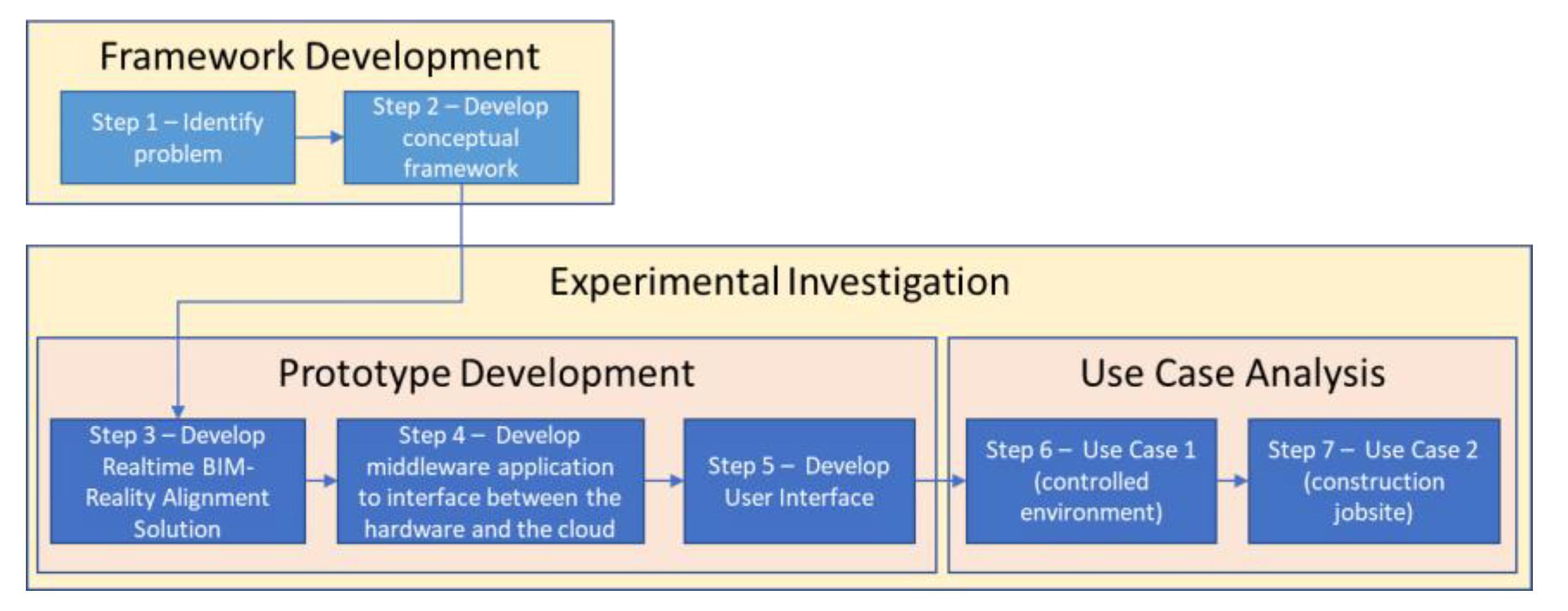
3. Research Methodology

The research methodology used in this study is shown in Figure 1. First, the study identified the problems in remote inspection through a background literature review. Then, a conceptual framework was developed for an integrated AR and quadruped robot solution for remote construction progress monitoring. The study further develops the concept of AR and remote inspection from previous literature. Then, through an experimental investigation, a working prototype of the proposed framework was developed. For that, the study developed an AR solution comprising the 3D model of the building extracted from its BIM model aligned with the live video stream of the job site for real-time interaction, as well as the back-end application development and user interface development. More information is provided on the developed computational framework in Section 4 and prototype development in Section 5.1.
The developed prototype was evaluated through two use case analyses. The first case is the Bishop-Favrao Hall on Virginia tech campus, which is a building in operation providing the opportunity to experiment with the prototype in a controlled environment. The second case is the live construction site of the Creativity and Innovation District (CID) on the Virginia Tech campus. The evaluation process is explained in more detail in Section 5.2. The system was also evaluated using expert feedback in the first use case while interacting remotely with the developed system to identify the challenges and recommendations for further development of the framework.

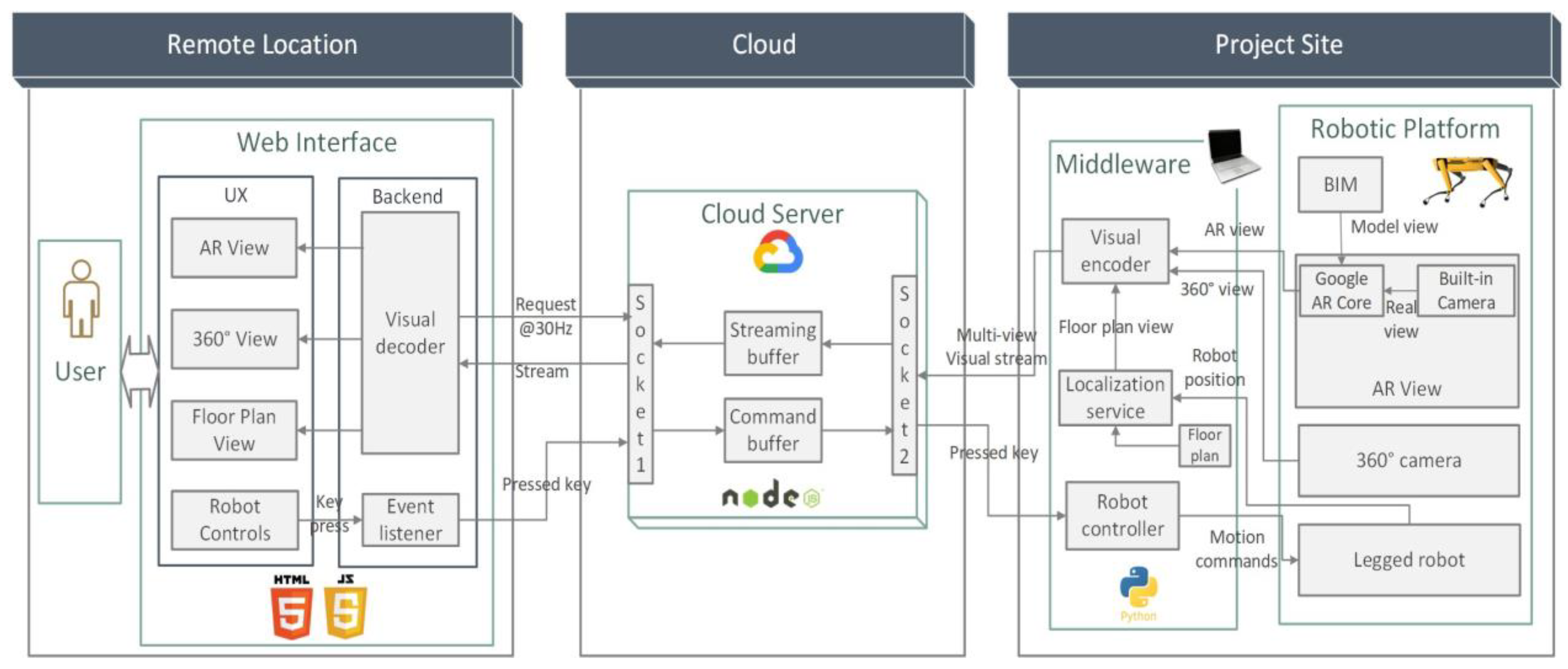
4. Proposed Computational Framework for Remote Construction Progress Monitoring

This study proposes a computational framework for real-time and remote robot-enabled construction progress monitoring that incorporates robot control, 360° real-time reality capture of the as-built status, and BIM-enabled AR in a web-based platform (see Figure 2). The four main components of the proposed framework include: (a) robot control to remotely control and navigate the quadruped robot through the construction site, (b) an AR model visualizing an as-planned 3D geometric model of the building from its BIM to compare it with the live as-built status of the job site, (c) a 2D floor plan for dynamic localization of the robot on the job site, and (d) livestreaming 360° video of the construction site to simultaneously provide panoramic and live visualization of the job site. Once logged in and authenticated, the user (who can be any project stakeholder performing remote construction progress monitoring) can see the web client in the web browser. The web client establishes and maintains a live connection with the cloud server, periodically requesting and receiving visual updates. The cloud server acts as a mediator between the project site and user.
At the project site, the robot serves as the user’s remote assistant. The robot’s software development kit (SDK) through its application programming interface (API) provides the robot control for its remote navigation. For on-site computation and communication, a middleware is also employed. The middleware is a software application that runs on a computer or local server at the location. The robot connects with the middleware via a local area network, such as a Wi-Fi access point. Both the robot and middleware must be connected to the same network. The middleware can be a single board computer (SBC) like Raspberry Pi installed on the robot or a desktop or laptop computer installed in the project office communicating with the robot over the Wi-Fi network at the job site. The middleware serves as a bridge between the cloud server and rest of the system. Following are the components of the proposed framework as shown in Figure 2:
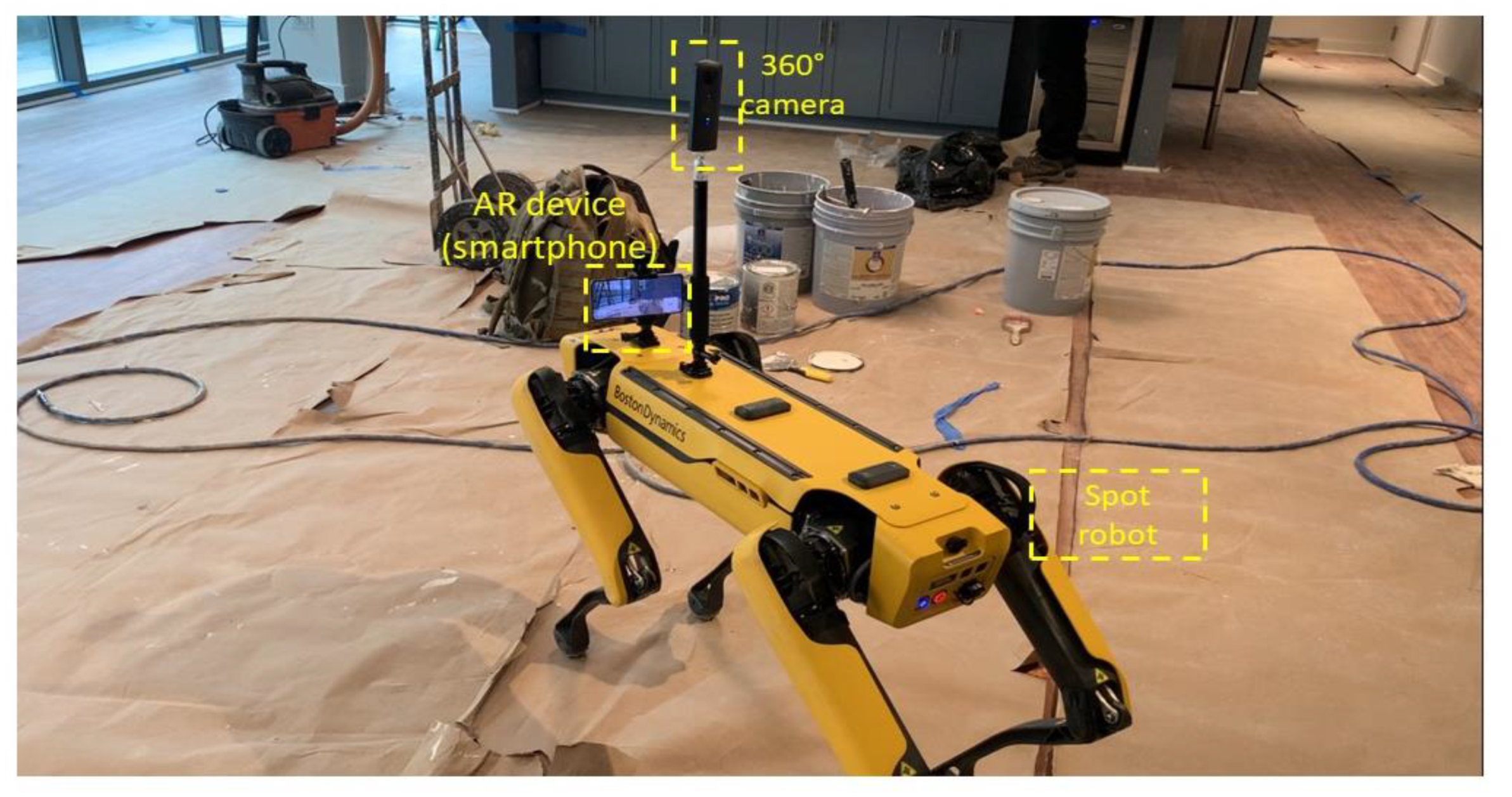
  • Robotic platform—The robotic platform is composed of a legged robot that can navigate through the unstructured environment of a construction site and across multiple floors. The robot is equipped with a 360° camera for a panoramic view of the robot’s surroundings for navigation, and an AR device that is typically a smartphone with an AR app.
  • Middleware—The middleware is a computing device either installed on the robot or at a fixed location in the construction site. The role of the middleware is to directly communicate with the robot and other hardware, pass user commands, and send the real-time information from the devices to the server. The middleware uses the robot’s application program interface (API) to control the robot.
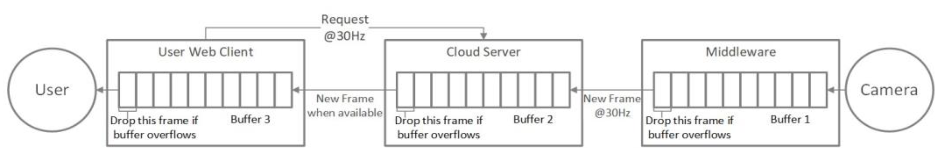
  • Cloud Server—The server separates the user from the project site and facilitates remote inspection. The server stores the latest image frames from the site and sends them to the Web Client when requested.
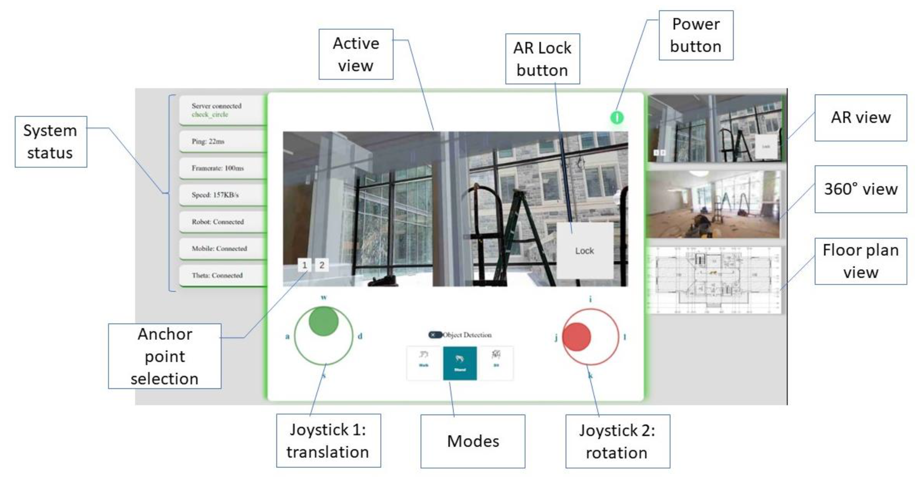
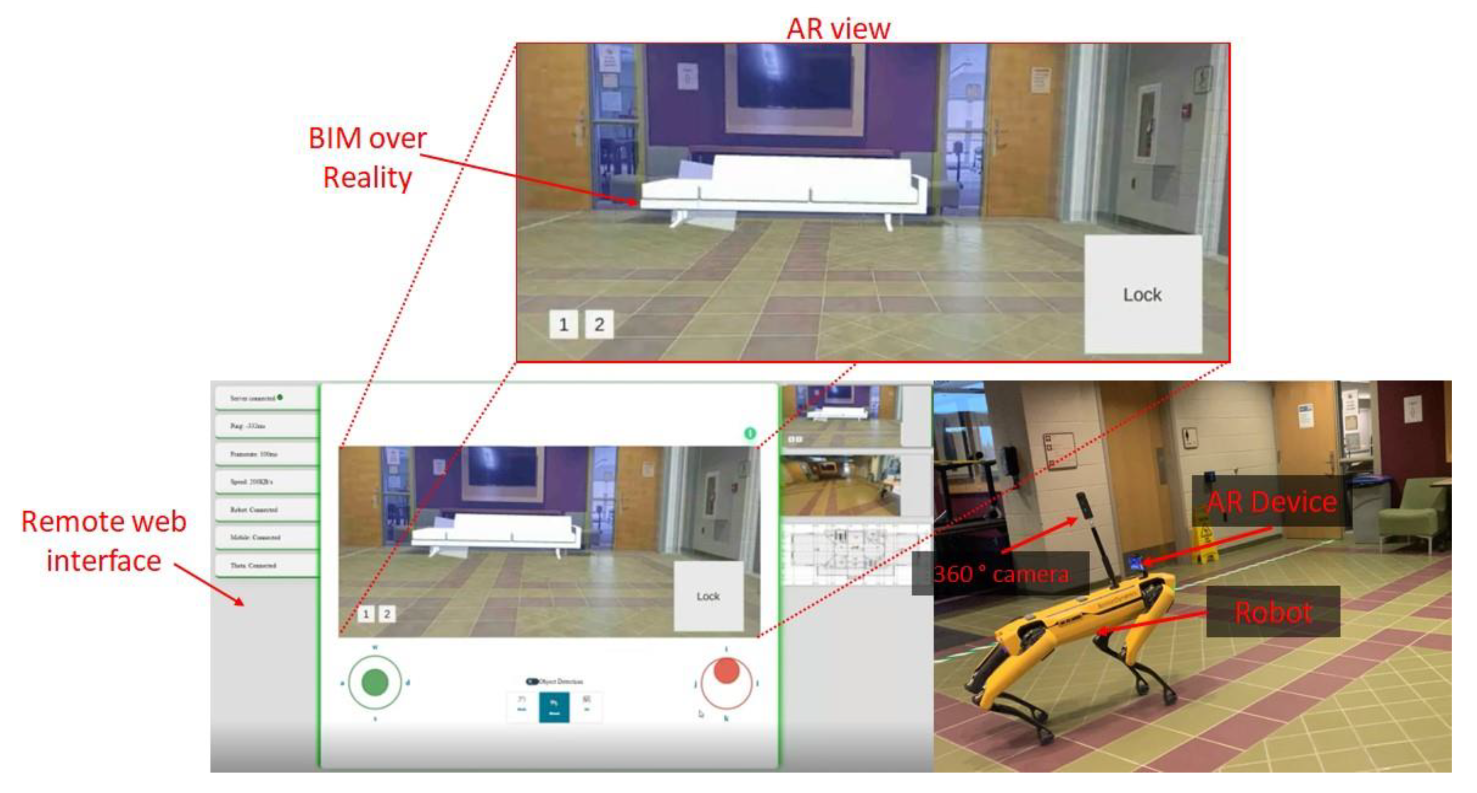
  • Web Client—This is the main user interface through which the user or remote inspector interacts with the system. The web client provides control options for the robot to sit, stand, or move around. Apart from controlling the robot, the user can switch between one of the three views:
    1.
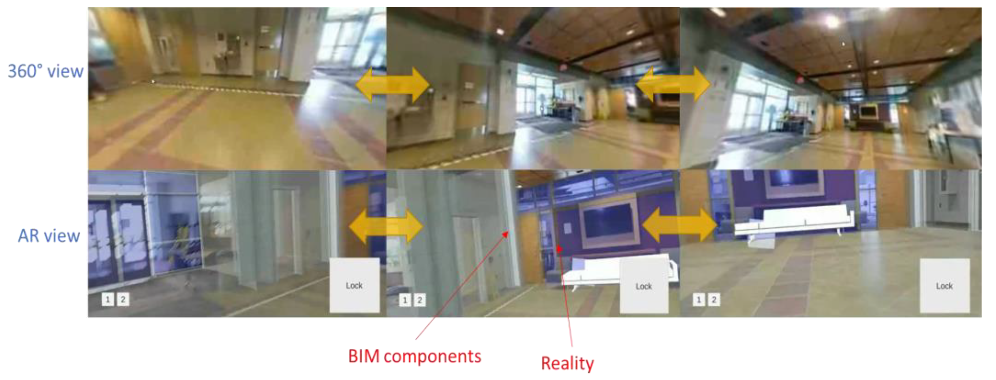
    AR View—This view shows the high-quality live stream of the site captured from the AR device on the robotic platform. The AR view shows an augmented reality environment by overlaying the BIM model on the live video feed of the job site.
    2.
    360° View—This view shows a 360° panoramic view of the site. This view is used for navigating the robot by providing the user an all-round visual of the robot’s surroundings on the job site.
    3.
    Floor Plan View—This view shows the robot’s current position on the floor plan of the building. This provides the user a bird’s eye view of the location being inspected.
  • User—The user is the remote inspector or project stakeholder monitoring the project from a remote location.
The robot is also equipped with data collection devices including a 360° camera and mobile device running an AR program referred to as the AR device. The 360° camera gives the user a panoramic view of its surroundings to help with remotely navigating the robot on the job site. Because the robot’s embedded cameras have a lower angle and low resolution, they cannot provide a clear view of the surroundings; therefore, an external camera is required. The AR device gives a high-quality image of the job site viewed in front of the robot. The AR device captures the reality before superimposing the BIM model aligned and anchored to the reality.

5. Evaluation of the Proposed Framework for Remote Construction Progress Monitoring

The proposed framework is evaluated through prototype development and experimental investigation. First, the framework is implemented as a working prototype that includes the components of the proposed framework. Then, we conducted two sets of experimental investigations in two use cases. The first use case is the controlled environment of the research lab at Virginia Tech and the second use case is a live construction project.

5.1. Implementation Approach

The hardware used in the implementation of the proposed framework includes Spot, a quadruped robot by Boston Dynamics as well as a Ricoh Theta V 360° camera and an Android device, both mounted on top of Spot. The network setup of the different hardware is shown in Figure 3. Implementation of the proposed framework is enabled by using Unity, Spot SDK, and Google Cloud Platform (GCP). The AR model is developed using the Unity engine, which uses the C# programming language for scripting. For robot control and localization, the Spot SDK is used, which is based on Python programming. Google Cloud is used as the backend server for remote control and data exchange. Debugging and testing of the software applications were performed manually by the research team.

5.1.1. Robotic Platform
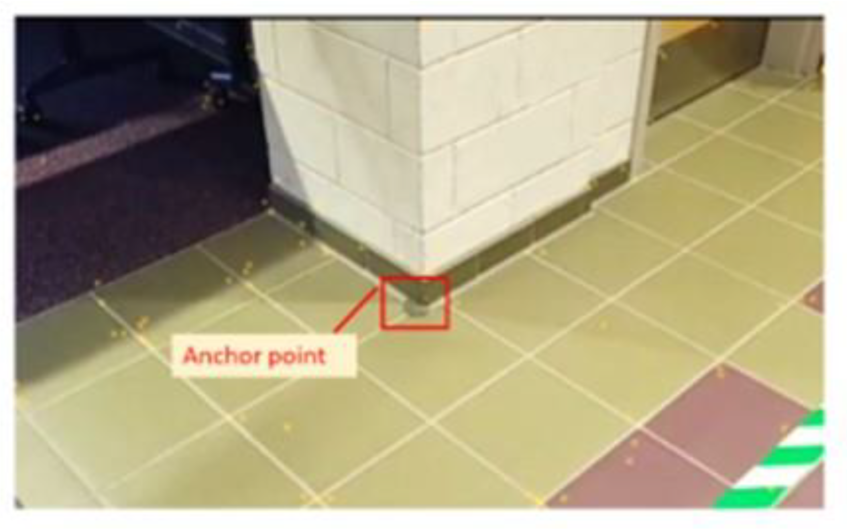
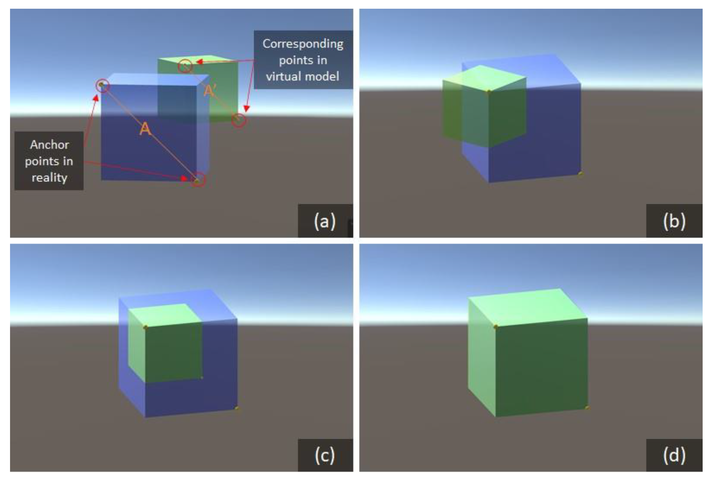
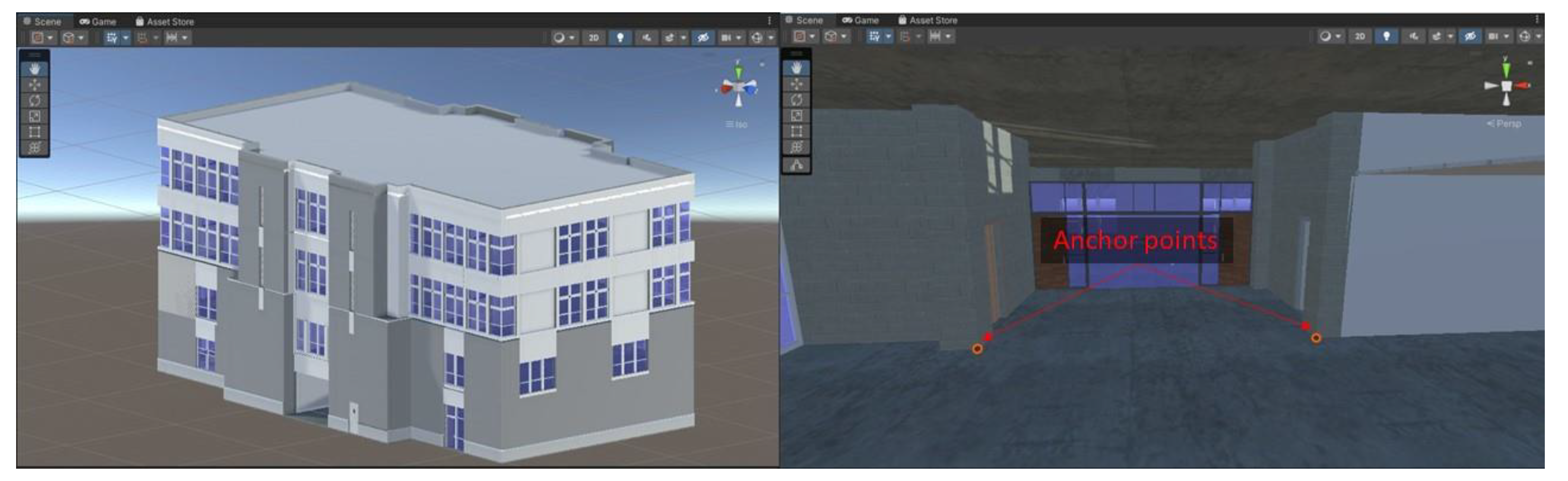
The robotic platform used in this study includes the Boston Dynamics Spot robot (v2.3.4), a 360° camera, and an Android smartphone. Spot weighs 32 kg (70.5 lbs) and can carry up to 14 kg (30.9 lbs). Spot has multiple sensors and motors in each leg to explore the environment and maintain its balance and posture [93]. Spot’s standing height is 840 mm (33.1 in), while its sitting height is 191 mm (7.5 in). Spot’s horizontal field of view for terrain detection is 360°, and its range is 4 m (13 feet) [93]. Spot’s typical run time with each of its two batteries is 90 min and its standby time is 180 min. Spot can traverse a variety of terrains but it can become unstable on slippery surfaces such as wet grass or moving platforms such as moving walkways or elevators [93]. Its operation also requires the lighting to be above 2 Lux. Spot’s collision avoidance system maintains a set distance from stationary obstacles and its distance for obstacle avoidance can be changed on its controller within a range between 0.1 to 0.5 m (4 in to 1.6 ft). It may not detect objects less than 30 cm (11.8 in) high, nor thin objects less than 3 cm (1.2 in) in thickness [93]. It can move on sloped surfaces up to 30° and move up and down the stairs with a 7” (18 cm) rise for a 10–11” (25–28 cm) run, but if it loses balance on the stairs or an incline, it may slip and fall [93]. When the robot is in operation, anyone around it should keep a 6.5-feet (2 m) distance from Spot from all sides and at all times to avoid risk of collision [93]. QR code-like fiducials placed along Spot’s path can assist with its localization to adjust its internal map with the real world. Spot has the in-built ability to track AprilTag fiducials. Spot’s SDK allows it to read its pose (position and rotation) in the space with respect to any fiducials it sees from its five stereo cameras. In this study, the location of the robot was tracked on a 2D floor plan of the building by installing a fiducial at a predetermined location.
The authors’ previous research [19] provides detailed information regarding Spot’s autonomy. In this study, to enable remote navigation and inspection capabilities in real-time by a remote inspector, Spot control over the web is used that is enabled by using Spot API. Spot API uses a client-server model and lets applications control Spot and read sensor information. Client applications can communicate with services running on Spot after establishing a network connection to Spot. The network connection can be any IP network including a direct Wi-Fi connection to the robot, privately-owned intranet, or public network. To command and operate Spot, a client must first establish authentication and then, the client can establish application-layer time synchronization and acquire a lease. Once fully in control of the robot, the client will need to (a) maintain the software stop using E-Stop Service, (b) enable motor power using Power Service to allow a client to power the motors on and off, and (c) send commands using Robot Command Service to allow a client to move the robot [94].
The 360° camera provides a panoramic view around the robot, which makes it easier for a remote inspector to observe the surroundings and maneuver the robot at construction sites. This study uses the Ricoh Theta V camera, which works by taking two fish-eye images from the two opposite sides of the camera, and digitally stitching them together to create a single 360° image. The final resolution of the image produced by the camera is 14 megapixels [95]. The live preview was extracted from the Ricoh Theta V every 100 milliseconds. The camera uses a WebAPI conforming to the open spherical camera (OSC) specifications by Google. The live images were retrieved using POST requests to the camera connected to the hosted network. The camera is mounted on top of Spot with a flat adhesive sticker attached to a base plastic mount, and a selfie stick to provide a higher angle view on top of Spot (Figure 4).

5.1.2. AR Model

This study uses Android’s built-in augmented reality framework ARCore for the implementation of the AR application and an Android-based Samsung Galaxy S21 smartphone for running the AR application on the job site. The smartphone serves two purposes. First, it performs high-quality reality capture onsite. Second, it augments the BIM model on top of the reality capture. ARCore uses the phone’s gyroscope and accelerometer data to track the position of the device in the virtual space. Therefore, the device should be equipped with gyroscope and accelerometer sensors to be used reliably with ARCore. The Android device is mounted on top of Spot with a flat adhesive sticker attached to a base plastic mount, and a phone holder mount to hold the Android smartphone (Figure 4).
This study uses the Unity game engine developed by Unity Technologies as the main platform for its required AR model. Unity integrates 3D modelling with scripting and allows augmented reality and virtual reality visualization capabilities. For the AR application, the BIM models of the two use cases in this study are used. The BIM models are exported from Revit. The building geometry was extracted in the FBX file format. The default FBX export option of Revit does not allow exporting of textures with the materials. The TwinMotion FBX exporter plugin for Revit was used to export the model with embedded textures. The ARFoundation library for Unity was used in this study for developing the prototype of the AR application. ARFoundation is built upon Google ARCore and Apple ARKit, which allows developers to develop cross-platform AR applications in Unity. It provides high-level functionalities that work on both iOS and Android platforms. ARCore tracks unique features from the visual stream that can be used to anchor virtual objects to reality. In this study, an anchor-based AR alignment method was used that uses unique points of interest in the reality to align the virtual object (BIM model in this case). The anchors were selected manually by the user. Corners of the columns were used in reality and BIM for anchoring of the model. An example is shown in Figure 5.
This study assumes that the vertical direction in the BIM model aligns with the vertical direction in reality. Due to this, 5 degrees of freedom are required to position and align the BIM model with the reality. Those are 3 positional, 1 rotational, and 1 scalar degree of freedom. Two degrees of freedom (rotations around the two horizontal axes) become zero from the above assumption. The degrees of freedom are resolved by selecting 2 anchor points in reality. The 6 positional variables of the 2 points provide enough information for the model alignment. Figure 6 shows the steps to align the virtual model (BIM) with the reality. First, the virtual model is positioned such that the first anchor coincides with the corresponding point in the model. The first step resolves 3 degrees of freedom. The line segment A in Figure 6a joins the 2 anchor points in reality, whereas line segment A’ joins the corresponding points in the model. The model is rotated around the vertical axis such that the line A aligns with line A’. Finally, the model is scaled by a factor that equals the ratio of the length of line A to that of line A’.

5.1.3. Dataflow Architecture

The detailed architecture of the prototype developed to evaluate the proposed framework is shown in Figure 7. The Spot robot used for this study hosts multiple network interfaces and can be connected with a WiFi network. A middleware program running on a laptop (with i7 9th generation processor, and 16 GB memory running Windows 10) is used mainly to process the data. The role of the middleware is to communicate with the robot and its attachments as well as the cloud server for data exchange. The laptop could be replaced with an embedded system like Nvidia Jetson board used by [80] the original equipment manufacturer (OEM) supplied by Spot Core processor to make the robot a self-sufficient and independent data collection tool. All the devices used for this study including the 360° camera, Android smartphone, and Spot are connected to the same network hosted as a mobile hotspot from the middleware. The middleware performs key functions of processing images from the 360° camera and AR camera, packaging them, and transmitting them to the cloud server.
To facilitate the remote control and inspection through the web interface, a prototype server was developed. The server was hosted on the Google Cloud Platform (GCP). GCP provides a low-cost infrastructure-as-a-service (IaaS) suite for rapid prototyping of cloud computing applications. The middleware reads data from the Android smartphone and 360° camera and encodes them into bytes. The byte codes are stored in memory in a JavaScript Object Notation (JSON) data structure. The structure of the JSON is shown in Figure 8. The JSON structure consisted of seven keys: (a) ‘ar’ is the byte code of the AR view from the AR device, (b) ‘theta’ is the byte code of the 360° image from the Ricoh Theta V camera, (c) ‘floor_plan’ is the byte code of the floor plan with the position of the robot indicated with an icon, (d) ‘status’ is the connection statuses of the different hardware, (e) ‘timestamp’ is the time when the data is sent from the middleware to the cloud, (f) ‘framerate’ is the frequency of sending data to the cloud in number of frames per second (fps), and (g) ‘data_size’ is the size of each frame. The middleware application uses the dynamic frame rate to send data to the cloud, i.e., initially it creates one frame every 100 milliseconds and adds to a buffer, as explained in Section 5.1.5, and monitors the buffer to increase/decrease the frame rate depending on the available capacity of the buffer. The server stores a copy of the latest frame in-memory and sends it to the client node when requested.
The client node consists of a web interface developed in HTML and JavaScript as shown in Figure 9. The client node sends a request to the server to fetch the latest frame at 30 Hz. The server returns a new frame if the frame in the memory is newer than the frame last sent to the same client. If no new frame is available, it ignores the request to prevent unnecessary clogging of the network. The web interface also provides remote control of the robot. Specific movements of the robot are mapped with specific keys and on-screen buttons. Whenever the client (remote user) presses a mapped key on the keyboard or clicks on an on-screen button, the message is sent to the server, which is relayed immediately to the robot node. The middleware processes the message, and depending on the key/button used, it sends the associated command to the robot using the robot’s API.

5.1.4. User Interface

The user interacts with the system through the web-client. The user interface of the web-client is designed as shown in Figure 9. The top-middle section of the interface shows the active view (from the views on the right-side thumbnails) selected by the user. Three views are available to the user on the right-side of the interface: the AR view, 360° camera view, and floor plan view. The user can choose one of the three views from the thumbnails gallery on the right section of the interface. The bottom half of the interface provides remote control options for the robot. The robot can operate in three different modes: stand, sit, and walk. The stand mode positions the robot standing on its feet. In the stand posture, the robot can look around by spinning its upper body section but cannot move. In other words, the joysticks (on the interface) can only be used to alter the robot’s pitch, roll, and yaw but not its location. Only after selecting the walk mode can the robot move. The left (green) joystick on the screen can be used to move the robot longitudinally or laterally in this mode. The right (red) joystick is used to turn the robot, i.e., change its yaw. The sit mode allows the robot to sit down and rest, which is the most stable and safest mode for the robot. As a result, when the user does not want to operate the robot, this mode should be selected. The system is designed to fall back to the ’sit’ mode if the connection between the user and the robot is lost due to network failure in any of the system layers.
The AR alignment is accomplished by choosing two anchor points in reality. The location of these anchor points is set up when the BIM model is loaded into the AR system. The user chooses these anchor points one at a time by first placing the robot such that the anchor point is visible in the AR view, then clicking on the point in the AR view, which sends the click location to the AR device through the cloud server and middleware. When the AR device gets the click location, it uses ray-tracing to locate a feature point at that place. The ARCore framework, which is utilized for the AR implementation in this study, automatically detects several distinct features in the image. The user can click on the Lock button to lock or unlock the alignment of BIM with reality. When the user clicks on the Lock button, the AR model uses the technique described in Section 5.1.2 to align the BIM model with reality. Once the BIM has been aligned with reality, the ARCore tracks the movement of the AR device to maintain the alignment. This allows the user to compare the model laid over the reality for the purpose of construction progress monitoring.

5.1.5. Optimization Strategy

Managing network latency is a significant difficulty when operating a robot remotely. The visuals are processed, encoded, and decoded several times due to the multi-tiered system architecture. The transmission of visual streams from the middleware to the cloud server and from the cloud server to the web client are the system’s primary bottlenecks. A naïve approach would deliver the frames in sequence as soon as they became available. The drawback with this strategy is that a momentary network outage or slowdown may jam the network pipeline due to pending frames, causing delays to accumulate over time. The same was observed during the preliminary testing using the naïve technique.
To optimize the network communication, multiple buffers were created in the middleware, cloud server, and web client. The buffers stored only ten (10) frames at any time and were implemented as a queue data structure following the first-in-first-out principle. At the middleware layer, a new frame is added to the tail end of the queue as it is available from the camera. At the same time, another thread would send one from the head of the queue to the cloud. If the network is slow and the frames are created faster than they are sent, the oldest frame from the head of the queue is dropped to accommodate a new frame at the tail. Therefore, the queue always contained the latest frames.
As can be seen from Figure 10, a similar buffer was created on the cloud server, which would store the latest ten (10) frames. As a request is received from the user side web-client, one frame is sent in response from the head of the queue, while a new frame received from the robot-side middleware is added to the tail of the queue.

5.2. Experimental Investigation

The proposed framework is evaluated through an experimental investigation using the developed prototype of the proposed framework. For this study, we conducted two sets of experimental investigations in two use cases. The first use case is the controlled environment of the research lab in Bishop-Favrao Hall (BFH) on the Virginia Tech campus. This use case served as a control setting for the evaluation of this research prior to the implementation on real-world construction sites. The second use case is a live construction project consisting of a 225,000-square-foot new student residence hall.

5.2.1. Use Case 1

The first experiment was conducted on the second floor of Bishop-Favrao Hall on the Virginia Tech campus in Blacksburg, VA, USA. The test involved a remote inspector located in Rhode Island, USA operating the robot for remote inspection and monitoring of the space while using the developed cloud-based prototype. The remote inspector, who had prior expertise in inspecting and monitoring construction sites, accessed the system remotely, while the robot was located in Blacksburg, VA. The test lasted about 19 min and 40 s. The targeted inspection area was approximately 1123.59 square feet. The experimental setup and user view as seen by the remote inspector is shown in Figure 11. The BIM model that was imported into Unity is shown in Figure 12. The two anchor points that were used to align the model can be seen on the right side of Figure 12. The anchors were set at the bottom of two columns that can be easily located in the building. Many factors influence the choice of anchor points. First and foremost, they should be easily accessible at the site. Second, they should not be too far apart; otherwise, the robot would have to go from one location to another for alignment, which is not time-efficient. However, the anchor points should not be too close to each other either, because a minor divergence in anchor selection might generate huge rotational errors in the alignment.
The remote inspector was able to move around the inspection area with the direct control of the robot using the on-screen controls and 360° live stream as shown in Figure 13. The experiment was also set up online using the Google Meet teleconferencing platform to provide the research team with direct feedback of the user. The experimental session was recorded for further analysis. The biggest challenge encountered during the experiment in use case 1 was the latency in sending the command, and accordingly seeing the robot movement in the camera by the remote user. The lag was caused by the low network bandwidth and server configuration of the free tier Google Cloud server used for the development. The latency varied between 300 and 2000 milliseconds. To avoid a deluge of motion commands all at once caused due to momentary slowdown in the communication pipeline, safety checks were added in the system to disregard any command sent more than 3 s ago. Although lags of up to 2000 ms were not found to have a significant influence on the inspection process, navigating the robot through a small space filled with obstacles and people can be challenging and hazardous with extended lags. The challenges faced during this experiment and suggestions of the inspection expert are presented in Table 1. The identified challenges are categorized into two categories: (a) related to hardware, and (b) related to software. The hardware-related challenges due to the limitations of the robot or the camera hardware can be overcome by using different hardware. The software-related challenges are limitations of the applications developed in this research. They serve as recommendations for future research and further development of the AR-based solution proposed in this study.

5.2.2. Use Case 2

The second experiment was conducted on a live construction site of a 225,000 sf student residence hall. The study experiment was conducted in one of the apartment units of 2949 sf. At the time of the experiments, the drywall installation work was being carried out. The BIM of the project was made available by the project’s general contractor for the research purpose, which was used in the AR application of the proposed framework. The same methodology as use case 1 was used in this experiment. The robot was controlled over the web and the site was inspected remotely through the web client. The experiment location was limited to the living room and kitchen area of the apartment on the second floor of the building. The area of the experimental setting was approximately 500 square feet. The time taken for the experiment was about 5 min excluding the setup time.
The robot setup and the user interface with the AR view for the second use case is shown in Figure 14. The web interface includes thumbnails for the live AR view, the 360° view and the plan view on the right-side of the interface while the AR view is active in Figure 14. Using the AR view in the prototype, it was easier to quickly compare the as-built status of the project with the model. The 360° live view of the job site allowed the operator/inspector to see the obstacles around the robot and easily navigate the robot through the space. The major challenges were the network lag and keeping the AR alignment stable. Also, since there were multiple obstacles, e.g., ladders, buckets of paint, cords, etc., the robot navigation faced some challenges including hazardous situations due to slippery floors covered with papers to protect the hardwood from paint, which the remote inspector might not fully recognize due to them being located remotely.

6. Discussion

The evaluation of the proposed framework suggests that using on-site quadruped robots and augmented reality can potentially provide a practical solution for real-time and remote inspection of construction projects. In construction progress monitoring, the sooner the project team can identify work progress issues, quality concerns, and deviations from the originally planned construction documents, the better the odds of finishing the project on time with high quality. Therefore, progress monitoring inspections should be done early and often during the project duration, and the use of the proposed framework in this research can provide an opportunity for more regular construction progress monitoring.
One of the challenges encountered during the framework implementation and evaluation was the communication latency between the user-side web-client and robotic platform. During the experimental investigation, a total latency of about 200 to 300 ms was observed in the system. In a human-machine interface, time delays between the user input action and corresponding visible outcome may arise due to many reasons, such as computation, communication, or mechanical limitations [96]. Such delays increase the cognitive workload on the user in successfully performing the intended task [96]. Bidirectional communication in the proposed framework is enabled by multiple layers of the system, beginning with the local network and progressing through the middleware, cloud server, and web-client. The communication bottleneck in the system due to the internet-based connectivity to the cloud server was partially resolved by implementing the optimization method explained in Section 5.1.5. The predictive AR system proposed by Sakib et al. [96] and Richter et al. [97] combining the visuals from the 360° and AR camera can be used to reduce the effect of the latency on the user’s performance with the system.
Another problem encountered throughout the study was matching the two perspectives in the AR app, namely, the reality and the BIM model. The AR framework utilized in this study tracks the device’s movement using image processing and inertial sensors. For AR tracking, this approach makes extensive use of numerical approximations. Because of approximation errors in the methods, the AR scene can lose alignment and two viewpoints can deviate from one another during the inspection session. These errors accumulate over time, increasing the deviations, which is referred to as “drift”. This is a restriction of the state of the art in AR, and thus of this study. The image-to-BIM registration method proposed by Asadi and Han [67] by matching the real and BIM perspectives for periodically correcting the alignment can be used with the proposed framework to reduce drift.
One challenge with the proposed framework identified during the experimental study in use case 1 was related to the hardware used for the prototype development and experimentation. The walking motion of the quadruped robot generated non-uniform acceleration that interfered with the camera focusing, which in turn (a) degraded the quality of the visuals, and (b) showed a potential increase on the cognitive load of the user. An active video stabilization technique using a combined inertial measurement unit (IMU), motorized gimbal, and software-based optical stabilization proposed by Windau and Itti [98] for UAVs can be used with quadruped robots as well to overcome this challenge.

7. Limitations and Future Work

In this study, the quality of alignment in the AR model was not empirically measured. Current augmented reality systems, including the one employed in this study, suffer from numerical error accumulation, i.e., drift, which causes the virtual content to drift out of alignment with reality over time. Future research should look into automating the AR alignment procedure. One method is to use natural markers in the scene, such as doors, windows, columns, and beams. Periodically realigning the views in AR by recognizing and matching these natural cues can help to reduce drift. The proposed solution also relies on a geometrically accurate BIM model of the building. Any deviations in the actual work from the BIM may not only cause misalignment between the BIM and real-life visuals but also affect the ability of the remote user to satisfactorily control the robot.
In this study, limited BIM data was utilized for visual comparison of the as-built status (i.e., live video stream) with the as-planned model (i.e., 3D BIM model) in the AR view. Primarily, the geometry, colors, and textures were used. Other data including the construction schedule can be used in a future study for schedule comparisons. In another study by the authors [99], data regarding the element type was used to define the walkable and non-walkable surfaces for the quadruped robot to guide the robot in walking through the doors and hallways. Thus, a similar approach can be implemented to extend the capabilities of the proposed AR integration in this study.
Construction safety is a significant factor when utilizing robots on construction sites. Because the robot is operated remotely, network failure or operator mistake can cause hazardous situations. To address this issue, a safety layer that detects and avoids hazardous obstacles can be added to the system in the future. The manufacturer of the Spot robot recommends using the robot at least 6.5 feet away from people. An object detection model capable of detecting humans in an image stream should be coupled with the robot control layer that demobilizes the robot if a human is identified within a specified radius of the robot. The authors previously studied the safety and other implications of using the Spot robot on construction sites and developed a standard operating procedure (SOP) for operating the robot on construction sites based on its limitations and manufacturer recommendations [19]. In addition to the safety layer, an autonomy layer can be added to the system, allowing the operator to choose a location on the floor plan, which the robot can autonomously navigate to. This can potentially reduce the cognitive load of the remote operator, allowing the inspector to focus on inspection tasks rather than robot navigation and only take over the robot control when needed. The BIM model and fiducials installed at site for robot localization on the floor plan can be used for autonomous robot navigation as proposed in [99].
Although quadruped robots are more versatile than wheeled robots, they are still unable to access many areas, such as in building facades, overhead shelves, and above-ceiling inspection. In this research, only a one-to-one human-robot partnership was considered, i.e., one operator controlling one robot. Future research may expand the proposed framework to integrate multiple types of robots, such as humanoids, drones, or wall-climbing robots to inspect locations that quadruped robots cannot access in one-to-many human-robot partnerships (one operator controlling multiple robots) or many-to-many human-robot partnerships (multiple operators interacting with multiple robots). As the human-robot team becomes more complex, the role of human interactions with the engineered system will become essential. Future studies should investigate interactions that may occur between human and robot partners and how those interactions will affect construction progress monitoring. Furthermore, future research can also conduct a comparative analysis of the proposed remote robot-enabled real-time construction progress monitoring with the conventional methods in terms of cost, time, error detection, and impact on the construction quality.

8. Conclusions

Construction progress monitoring involves a set of inspections done by multiple project stakeholders, e.g., the owner, project architects, and engineers. Progress monitoring is currently performed through in-person site visits to assure quality, safety, timeliness, and legal compliance of the construction work. These in-person inspections require significant resources in traveling including time and travel cost, which eventually limits the frequency of inspections for construction progress monitoring. Infrequent inspections can prevent timely discovery of errors, which may cost significantly more to remediate in later stages of the construction process. This study has proposed a new computational framework for real-time and remote monitoring of construction projects using a teleoperated quadruped robot as an on-site agent for the remote inspector. Also, the study has developed a remote AR solution to provide a real-time visual stream of the construction work registered/aligned with the 3D geometric model of the building that is extracted from the BIM model to support remote inspection and monitoring work. In fact, the proposed framework provides a real-time and remote view of the project site through the 360° camera for a live panoramic visualization of the project site around the quadruped robot as well as the AR view of the project. In this AR view, the BIM geometry is embedded and registered with the representation of physical world data (i.e., live video stream of the construction site) creating the augmented reality view. The BIM model in this study is exported from Autodesk Revit in the FBX file format to extract the building geometry with embedded textures. To anchor virtual objects to the live video stream in the AR model, an anchor-based AR alignment method was used to align the virtual object (i.e., BIM geometry) with reality (i.e., live video stream of the construction site). This AR solution allows the remote inspector to be informed of the actual construction work performed in real-time and the current status of the project. It also allows the remote inspector to visually compare the as-built status of the project with the BIM model of the building. The proposed framework and AR solution were implemented and evaluated in two use cases: the controlled environment of the research lab and a live construction site. The AR technique applied in this study makes considerable use of numerical approximations for tracking the position of the device in the three-dimensional world. Due to these approximations, the AR scene can lose alignment and the two views can deviate from one another during the inspection session due to “drift”, which has been addressed by manual adjustments in this study. This limitation can be overcome through automatic alignment correction in future research.
The experimental investigations in this research indicate the potential of using quadruped robots for remote construction progress monitoring work. The scope of this study, however, is limited to only using the geometry, colors, and textures of the building elements extracted from the BIM model and does not take into consideration other information from BIM, such as the project schedule, schedule dependencies between components, or other BIM data. The findings of this study can be used by construction management teams to utilize quadruped robots on construction sites for remote and real-time monitoring of projects that can improve the frequency of construction inspections. The proposed framework in this study can also be useful to guide future research in analyzing the impact of using quadruped robots and AR for real-time remote construction progress monitoring.

Author Contributions

Conceptualization, K.A.; methodology, S.H. and K.A.; software, S.H.; validation, S.H. and K.A.; formal analysis, S.H.; investigation, S.H., K.A., J.S. and M.E.; resources, K.A., J.S. and W.T.; writing—original draft preparation, S.H. and K.A.; writing—review and editing, S.H., K.A., J.S. and S.D.; visualization, S.H. and K.A.; supervision, K.A. and S.D.; funding acquisition, K.A., S.D. and W.T. All authors have read and agreed to the published version of the manuscript.

Funding

This research was partly funded by Procon Consulting grant number 460873.

Data Availability Statement

The data presented in this study are available on request from the corresponding author. The data are not publicly available as they are confidential.

Conflicts of Interest

The authors declare no conflict of interest.

References

  1. Golparvar-Fard, M.; Peña-Mora, F.; Savarese, S. D4AR-a 4-dimensional augmented reality model for automating construction progress monitoring data collection, processing and communication. J. Inf. Technol. Constr. 2009, 14, 129–153. [Google Scholar]
  2. Lin, J.J.; Golparvar-Fard, M. Visual and virtual progress monitoring in Construction 4.0. In Construction 4.0; Routledge: London, UK, 2020; pp. 240–263. [Google Scholar] [CrossRef]
  3. Alizadehsalehi, S.; Yitmen, I. A Concept for Automated Construction Progress Monitoring: Technologies Adoption for Benchmarking Project Performance Control. Arab. J. Sci. Eng. 2019, 44, 4993–5008. [Google Scholar] [CrossRef]
  4. Golparvar-Fard, M.; Peña-Mora, F.; Savarese, S. Automated Progress Monitoring Using Unordered Daily Construction Photographs and IFC-Based Building Information Models. J. Comput. Civ. Eng. 2015, 29, 4014025. [Google Scholar] [CrossRef]
  5. Khairadeen Ali, A.; Lee, O.J.; Lee, D.; Park, C. Remote Indoor Construction Progress Monitoring Using Extended Reality. Sustainability 2021, 13, 2290. [Google Scholar] [CrossRef]
  6. Mohamed, M.; Tran, D. Exploring the Use of Mobile Technologies for Highway Construction Inspection. In Proceedings of the Construction Research Congress, Arlington, VA, USA, 9–12 March 2022; pp. 689–697. [Google Scholar]
  7. Alirezaei, S.; Taghaddos, H.; Ghorab, K.; Tak, A.N.; Alirezaei, S. BIM-augmented reality integrated approach to risk management. Autom. Constr. 2022, 141, 104458. [Google Scholar] [CrossRef]
  8. Chi, H.L.; Kim, M.K.; Liu, K.Z.; Thedja, J.P.P.; Seo, J.; Lee, D.E. Rebar inspection integrating augmented reality and laser scanning. Autom. Constr. 2022, 136, 104183. [Google Scholar] [CrossRef]
  9. Albert, A.; Hallowell, M.R.; Kleiner, B.; Chen, A.; Golparvar-Fard, M. Enhancing Construction Hazard Recognition with HighFidelity Augmented Virtuality. J. Constr. Eng. Manag. 2014, 140, 04014024. [Google Scholar] [CrossRef]
  10. Behzadan, A.H.; Kamat, V.R. Enabling discovery-based learning in construction using telepresent augmented reality. Autom. Constr. 2013, 33, 3–10. [Google Scholar] [CrossRef]
  11. Wang, X.; Love, P.E.; Kim, M.J.; Wang, W. Mutual awareness in collaborative design: An Augmented Reality integrated telepresence system. Comput. Ind. 2014, 65, 314–324. [Google Scholar] [CrossRef]
  12. Ivanov, D. Mobile Robots Groups Use for Monitoring and Data Collection in Continuous Missions with Limited Communications. In Software Engineering Perspectives in Intelligent Systems; Silhavy, R., Silhavy, P., Prokopova, Z., Eds.; CoMeSySo 2020: Advances in Intelligent Systems and Computing; Springer: Berlin/Heidelberg, Germany, 2020; Volume 1294. [Google Scholar] [CrossRef]
  13. Afsari, K.; Gupta, S.; Afkhamiaghda, M.; Lu, Z. Applications of Collaborative Industrial Robots in Building Construction. In Proceedings of the 54th ASC Annual International Conference Proceedings, Minneapolis, MN, USA, 17–21 April 2018; pp. 472–479. [Google Scholar]
  14. Truong, P.; Hölttä-Otto, K.; Becerril, P.; Turtiainen, R.; Siltanen, S. Multi-User Virtual Reality for Remote Collaboration in Construction Projects: A Case Study with High-Rise Elevator Machine Room Planning. Electronics 2021, 10, 2806. [Google Scholar] [CrossRef]
  15. Tea, S.; Panuwatwanich, K.; Ruthankoon, R.; Kaewmoracharoen, M. Multiuser immersive virtual reality application for real-time remote collaboration to enhance design review process in the social distancing era. J. Eng. Des. Technol. 2022, 20, 281–298. [Google Scholar] [CrossRef]
  16. Kopsida, M.; Brilakis, I.; Vela, P. A Review of Automated Construction Progress and Inspection Methods. In Proceedings of the 32nd CIB W78 Conference on Construction IT, Eindhoven, The Netherlands, 26–29 October 2015; pp. 421–431. [Google Scholar]
  17. Zhang, C.; Arditi, D. Automated progress control using laser scanning technology. Autom. Constr. 2013, 36, 108–116. [Google Scholar] [CrossRef]
  18. Napolitano, R.; Blyth, A.; Glisic, B. Spherical imaging and virtual environments for structural health monitoring. In Proceedings of the SHMII 2017-8th International Conference on Structural Health Monitoring of Intelligent Infrastructure, Brisbane, Australia, 5–8 December 2017; pp. 398–404. [Google Scholar]
  19. Afsari, K.; Halder, S.; Ensafi, M.; De Vito, S.; Serdakowski, J. Fundamentals and Prospects of Four-Legged Robot Application in Construction Progress Monitoring. In Proceedings of the ASC International Proceedings of the Annual Conference, Online, 5–9 April 2021; pp. 271–278. [Google Scholar]
  20. Phillips, S.; Narasimhan, S. Automating Data Collection for Robotic Bridge Inspections. J. Bridge Eng. 2019, 24, 04019075. [Google Scholar] [CrossRef]
  21. Omar, H.; Mahdjoubi, L.; Kheder, G. Towards an automated photogrammetry-based approach for monitoring and controlling construction site activities. Comput. Ind. 2018, 98, 172–182. [Google Scholar] [CrossRef]
  22. Golparvar-Fard, M.; Asce, M.; Peña-Mora, F.; Savarese, S. Integrated Sequential As-Built and As-Planned Representation with D4AR Tools in Support of Decision-Making Tasks in the AEC/FM Industry. J. Constr. Eng. Manag. 2011, 137, 1099–1116. [Google Scholar] [CrossRef]
  23. Klein, L.; Li, N.; Becerik-Gerber, B. Imaged-based verification of as-built documentation of operational buildings. Autom. Constr. 2012, 21, 161–171. [Google Scholar] [CrossRef]
  24. Brilakis, I.; Soibelman, L. Content-Based Search Engines for construction image databases. Autom. Constr. 2005, 14, 537–550. [Google Scholar] [CrossRef]
  25. Chen, J.; Cho, Y.K. Point-to-point Comparison Method for Automated Scan-vs-BIM Deviation Detection. In Proceedings of the 17th International Conference on Computing in Civil and Building Engineering, Tampere, Finland, 5–7 June 2018. [Google Scholar]
  26. Du, J.; Shi, Y.; Zou, Z.; Zhao, D. CoVR: Cloud-based multiuser virtual reality headset system for project communication of remote users. J. Constr. Eng. Manag. 2018, 144, 4017109. [Google Scholar] [CrossRef]
  27. Lin, Z.; Petzold, F.; Ma, Z. A Real-Time 4D Augmented Reality System for Modular Construction Progress Monitoring. In Proceedings of the 36th International Symposium on Automation and Robotics in Construction (ISARC), Banff, AB, Canada, 21–24 May 2019; Al-Hussein, M., Ed.; Curran Associates, Inc.: Red Hook, NY, USA, 2019; pp. 743–748. [Google Scholar] [CrossRef]
  28. Halder, S.; Afsari, K. Real-time Construction Inspection in an Immersive Environment with an Inspector Assistant Robot. EPiC Ser. Built Environ. 2022, 3, 389–397. [Google Scholar] [CrossRef]
  29. Brito, C.; Alves, N.; Magalhães, L.; Guevara, M. BIM mixed reality tool for the inspection of heritage buildings. ISPRS Ann. Photogramm. Remote Sens. Spat. Inf. Sci. 2019, IV-2/W6, 25–29. [Google Scholar] [CrossRef] [Green Version]
  30. Ribeiro, D.; Santos, R.; Shibasaki, A.; Montenegro, P.; Carvalho, H.; Calçada, R. Remote inspection of RC structures using unmanned aerial vehicles and heuristic image processing. Eng. Fail. Anal. 2020, 117, 104813. [Google Scholar] [CrossRef]
  31. Pang, J. Analysis of Remote Quality Inspection System for Construction Projects. In Proceedings of the 13th International Conference on Enterprise Information Systems, Beijing, China, 8-11 June 2011; SciTePress-Science and Technology Publications: Setúbal, Portugal, 2011; pp. 341–344. [Google Scholar] [CrossRef] [Green Version]
  32. Zhang, S.; Bogus Susan, M.; Lippitt Christopher, D.; Kamat, V.; Lee, S.H. Implementing Remote-Sensing Methodologies for Construction Research: An Unoccupied Airborne System Perspective. J. Constr. Eng. Manag. 2022, 148, 03122005. [Google Scholar] [CrossRef]
  33. Song, D.; Hu, Q.; Qin, N.; Goldberg, K. Automating inspection and documentation of remote building construction using a robotic camera. In Proceedings of the IEEE International Conference on Automation Science and Engineering, Edmonton, AB, Canada, 1–2 August 2005; pp. 172–177. [Google Scholar] [CrossRef] [Green Version]
  34. Obradović, R.; Vasiljević, I.; Kovačević, D.; Marinković, Z.; Farkas, R. Drone Aided Inspection during Bridge Construction. In Proceedings of the 2019 Zooming Innovation in Consumer Technologies Conference (ZINC), Novi Sad, Serbia, 29–30 May 2019; pp. 1–4. [Google Scholar] [CrossRef]
  35. Mattioli, L.; Cardoso, A.; Lamounier, E. 2D–3D spatial registration for remote inspection of power substations. Energies 2020, 13, 6209. [Google Scholar] [CrossRef]
  36. Linn, C.; Bender, S.; Prosser, J.; Schmitt, K.; Werth, D. Virtual remote inspection—A new concept for virtual reality enhanced real-time maintenance. In Proceedings of the 2017 23rd International Conference on Virtual System & Multimedia (VSMM), Dublin, Ireland, October 31–November 4, 2017; IEEE: New York, NY, USA, 2017; pp. 1–6. [Google Scholar]
  37. Kim, K.; Kim, H.; Kim, H. Image-based construction hazard avoidance system using augmented reality in wearable device. Autom. Constr. 2017, 83, 390–403. [Google Scholar] [CrossRef]
  38. Wang, X. Using augmented reality to plan virtual construction worksite. Int. J. Adv. Robot. Syst. 2007, 4, 42. [Google Scholar] [CrossRef]
  39. Lin, T.H.; Liu, C.H.; Tsai, M.H.; Kang, S.C. Using augmented reality in a multiscreen environment for construction discussion. J. Comput. Civ. Eng. 2015, 29, 04014088. [Google Scholar] [CrossRef]
  40. Wang, X.; Dunston, P.S. Design, strategies, and issues towards an augmented reality-based construction training platform. J. Inf. Technol. Constr. 2007, 12, 363–380. [Google Scholar]
  41. Kwiatek, C.; Sharif, M.; Li, S.; Haas, C.; Walbridge, S. Impact of augmented reality and spatial cognition on assembly in construction. Autom. Constr. 2019, 108, 102935. [Google Scholar] [CrossRef]
  42. Behzadan, A.H.; Kamat, V.R. Integrated Information Modeling and Visual Simulation of Engineering Operations using Dynamic Augmented Reality Scene Graphs. ITcon 2011, 16, 259–278. [Google Scholar]
  43. Sangiorgio, V.; Martiradonna, S.; Fatiguso, F.; Lombillo, I. Augmented reality based-decision making (AR-DM) to support multi-criteria analysis in constructions. Autom. Constr. 2021, 124, 103567. [Google Scholar] [CrossRef]
  44. Dong, S.; Behzadan, A.H.; Chen, F.; Kamat, V.R. Collaborative visualization of engineering processes using tabletop augmented reality. Adv. Eng. Softw. 2013, 55, 45–55. [Google Scholar] [CrossRef]
  45. Hammad, A.; Wang, H.; Mudur, S.P. Distributed Augmented Reality for Visualizing Collaborative Construction Tasks. J. Comput. Civ. Eng. 2009, 23, 418–427. [Google Scholar] [CrossRef]
  46. Li, X.; Yi, W.; Chi, H.L.; Wang, X.; Chan, A.P. A critical review of virtual and augmented reality (VR/AR) applications in construction safety. Autom. Constr. 2018, 86, 150–162. [Google Scholar] [CrossRef]
  47. Bosché, F.; Abdel-Wahab, M.; Carozza, L. Towards a Mixed Reality System for Construction Trade Training. J. Comput. Civ. Eng. 2015, 30, 04015016. [Google Scholar] [CrossRef]
  48. Lin, T.J.; Duh, H.B.L.; Li, N.; Wang, H.Y.; Tsai, C.C. An investigation of learners’ collaborative knowledge construction performances and behavior patterns in an augmented reality simulation system. Comput. Educ. 2013, 68, 314–321. [Google Scholar] [CrossRef]
  49. Hou, L.; Wang, X.; Bernold, L.; Love, P.E.D. Using Animated Augmented Reality to Cognitively Guide Assembly. J. Comput. Civ. Eng. 2013, 27, 439–451. [Google Scholar] [CrossRef]
  50. Chalhoub, J.; Ayer, S.K. Using Mixed Reality for electrical construction design communication. Autom. Constr. 2018, 86, 1–10. [Google Scholar] [CrossRef]
  51. Bae, H.; Golparvar-Fard, M.; White, J. Image-Based Localization and Content Authoring in Structure-from-Motion Point Cloud Models for Real-Time Field Reporting Applications. J. Comput. Civ. Eng. 2014, 29, B4014008. [Google Scholar] [CrossRef]
  52. Yeh, K.C.; Tsai, M.H.; Kang, S.C. On-Site Building Information Retrieval by Using Projection-Based Augmented Reality. J. Comput. Civ. Eng. 2012, 26, 342–355. [Google Scholar] [CrossRef]
  53. Hatem, W.; Maula, B. Improving Project Monitoring by Integrating BIM with Augmented Reality. Int. Rev. Civ. Eng. 2020, 11, 2020. [Google Scholar] [CrossRef]
  54. Kopsida, M.; Brilakis, I. Real-Time Volume-to-Plane Comparison for Mixed Reality–Based Progress Monitoring. J. Comput. Civ. Eng. 2020, 34, 04020016. [Google Scholar] [CrossRef]
  55. Zaher, M.; Greenwood, D.; Marzouk, M. Mobile augmented reality applications for construction projects. Constr. Innov. 2018, 18, 152–166. [Google Scholar] [CrossRef] [Green Version]
  56. Soman, R.K.; Whyte, J.K. A Framework for Cloud-Based Virtual and Augmented Reality Using Real-Time Information for Construction Progress Monitoring. In Proceedings of the Joint Conference on Computing in Construction (JC3), Heraklion, Greece, 4–7 July 2017; pp. 833–840. [Google Scholar]
  57. Omar, T.; Nehdi, M.L. Data acquisition technologies for construction progress tracking. Autom. Constr. 2016, 70, 143–155. [Google Scholar] [CrossRef]
  58. Kwon, O.S.; Park, C.S.; Lim, C.R. A defect management system for reinforced concrete work utilizing BIM, image-matching and augmented reality. Autom. Constr. 2014, 46, 74–81. [Google Scholar] [CrossRef]
  59. Zollmann, S.; Hoppe, C.; Kluckner, S.; Poglitsch, C.; Bischof, H.; Reitmayr, G. Augmented Reality for Construction Site Monitoring and Documentation. Proc. IEEE 2014, 102, 137–154. [Google Scholar] [CrossRef]
  60. Shin, D.H.; Dunston, P.S. Evaluation of Augmented Reality in steel column inspection. Autom. Constr. 2009, 18, 118–129. [Google Scholar] [CrossRef]
  61. Navon, R.; Sacks, R. Assessing research issues in Automated Project Performance Control (APPC). Autom. Constr. 2007, 16, 474–484. [Google Scholar] [CrossRef]
  62. Zavadskas, E.K.; Vilutiene, T.; Turskis, Z.; Šaparauskas, J. Multi-criteria analysis of Projects’ performance in construction. Arch. Civ. Mech. Eng. 2014, 14, 114–121. [Google Scholar] [CrossRef]
  63. Navon, R. Research in automated measurement of project performance indicators. Autom. Constr. 2007, 16, 176–188. [Google Scholar] [CrossRef]
  64. Pučko, Z.; Šuman, N.; Rebolj, D. Automated continuous construction progress monitoring using multiple workplace real time 3D scans. Adv. Eng. Inform. 2018, 38, 27–40. [Google Scholar] [CrossRef]
  65. Alizadeh Salehi, S.; Yitmen, I. Modeling and analysis of the impact of BIM-based field data capturing technologies on automated construction progress monitoring. Int. J. Civ. Eng. 2018, 16, 1669–1685. [Google Scholar] [CrossRef]
  66. Kamaruddin, S.S.; Mohammad, M.F.; Mahbub, R. Barriers and impact of mechanisation and automation in construction to achieve better quality products. Procedia-Soc. Behav. Sci. 2016, 222, 111–120. [Google Scholar] [CrossRef] [Green Version]
  67. Khashayar, A.; Hariharan, R.; Mojtaba, N.; Kevin, H. Real-Time Image Localization and Registration with BIM Using Perspective Alignment for Indoor Monitoring of Construction. J. Comput. Civ. Eng. 2019, 33, 4019031. [Google Scholar] [CrossRef]
  68. Adán, A.; Quintana, B.; Prieto, S.A.; Bosché, F. An autonomous robotic platform for automatic extraction of detailed semantic models of buildings. Autom. Constr. 2020, 109, 102963. [Google Scholar] [CrossRef]
  69. Asadi, K.; Ramshankar, H.; Pullagurla, H.; Bhandare, A.; Shanbhag, S.; Mehta, P.; Kundu, S.; Han, K.; Lobaton, E.; Wu, T. Vision-based integrated mobile robotic system for real-time applications in construction. Autom. Constr. 2018, 96, 470–482. [Google Scholar] [CrossRef]
  70. Bang, S.; Kim, H.; Kim, H. UAV-based automatic generation of high-resolution panorama at a construction site with a focus on preprocessing for image stitching. Autom. Constr. 2017, 84, 70–80. [Google Scholar] [CrossRef]
  71. Lee, J.H.; Park, J.; Jang, B. Design of Robot based Work Progress Monitoring System for the Building Construction Site. In Proceedings of the 2018 International Conference on Information and Communication Technology Convergence (ICTC), Jeju Island, Republic of Korea, 17–19 October 2018; pp. 1420–1422. [Google Scholar]
  72. Prieto, S.A.; de Soto, B.; Adan, A. A Methodology to Monitor Construction Progress Using Autonomous Robots. In Proceedings of the 37th International Symposium on Automation and Robotics in Construction (ISARC), Kitakyushu, Japan, 27–28 October 2020; pp. 1515–1522. [Google Scholar]
  73. Siciliano, B.; Khatib, O. Robotics and the handbook. In Springer Handbook of Robotics; Springer International Publishing: Berlin/Heidelberg, Germany, 2016; pp. 1–6. [Google Scholar] [CrossRef]
  74. Lattanzi, D.; Miller, G. Review of robotic infrastructure inspection systems. J. Infrastruct. Syst. 2017, 23, 04017004. [Google Scholar] [CrossRef]
  75. Wang, B.; Chen, X.; Wang, Q.; Liu, L.; Zhang, H.; Li, B. Power line inspection with a flying robot. In Proceedings of the 2010 1st International Conference on Applied Robotics for the Power Industry, Montreal, QU, Canada, 5–7 October 2010; pp. 1–6. [Google Scholar] [CrossRef]
  76. Dios, J.R.M.D.; Ollero, A. Automatic Detection of Windows Thermal Heat Losses in Buildings Using UAVs. In Proceedings of the 2006 World Automation Congress, Dalian, China, 21–23 June 2006; pp. 1–6. [Google Scholar] [CrossRef]
  77. Whang, S.H.; Kim, D.H.; Kang, M.S.; Cho, K.; Park, S.; Son, W.H. Development of a Flying Robot System for Visual Inspection of Bridges. In Proceedings of the Ishmii- Int Soc Structural Health Monitoring Intelligent Infrastructure, Winnipeg, MB, Canada, 13 November 2007. [Google Scholar]
  78. Moud, H.I.; Zhang, X.; Flood, I.; Shojaei, A.; Zhang, Y.; Capano, C. Qualitative and Quantitative Risk Analysis of Unmanned Aerial Vehicle Flights on Construction Job Sites: A Case Study. Int. J. Adv. Intell. Syst. 2019, 12, 135–146. [Google Scholar]
  79. Siebert, S.; Teizer, J. Mobile 3D mapping for surveying earthwork projects using an Unmanned Aerial Vehicle (UAV) system. Autom. Constr. 2014, 41, 1–14. [Google Scholar] [CrossRef]
  80. Asadi, K.; Chen, P.; Han, K.; Wu, T.; Lobaton, E. Real-time scene segmentation using a light deep neural network architecture for autonomous robot navigation on construction sites. In Computing in Civil Engineering 2019: Data, Sensing, and Analytics; American Society of Civil Engineers: Reston, VA, USA, 2019; pp. 320–327. [Google Scholar]
  81. Ibrahim, A.; Sabet, A.; Golparvar-Fard, M. BIM-driven mission planning and navigation for automatic indoor construction progress detection using robotic ground platform. In Proceedings of the European Conference on Computing in Construction, Crete, Greece, 10–12 July 2019; pp. 10–12. [Google Scholar]
  82. Kreuzer, E.; Pinto, F.C. Sensing the Position of a Remotely Operated Underwater Vehicle. In Theory and Practice of Robots and Manipulators; Morecki, A., Bianchi, G., Jaworek, K., Eds.; Springer: Vienna, Australia, 1995; pp. 323–328. [Google Scholar]
  83. Brunete, A.; Hernando, M.; Torres, J.E.; Gambao, E. Heterogeneous multi-configurable chained microrobot for the exploration of small cavities. Autom. Constr. 2012, 21, 184–198. [Google Scholar] [CrossRef]
  84. Longo, D.; Muscato, G. Adhesion Control for the Alicia3 Climbing Robot. In Climbing and Walking Robots; Springer: Berlin/Heidelberg, Germany, 2005; pp. 1005–1015. [Google Scholar]
  85. Hwangbo, J.; Lee, J.; Dosovitskiy, A.; Bellicoso, D.; Tsounis, V.; Koltun, V.; Hutter, M. Learning agile and dynamic motor skills for legged robots. Sci. Robot. 2019, 4, eaau5872. [Google Scholar] [CrossRef] [Green Version]
  86. Faigl, J.; Cížek, P. Adaptive locomotion control of hexapod walking robot for traversing rough terrains with position feedback only. Robot. Auton. Syst. 2019, 116, 136–147. [Google Scholar] [CrossRef]
  87. Lin, J.L.; Hwang, K.S.; Jiang, W.C.; Chen, Y.J. Gait balance and acceleration of a biped robot based on Q-learning. IEEE Access 2016, 4, 2439–2449. [Google Scholar] [CrossRef]
  88. Grandia, R.; Taylor, A.J.; Ames, A.D.; Hutter, M. Multi-layered safety for legged robots via control barrier functions and model predictive control. In Proceedings of the IEEE International Conference on Robotics and Automation (ICRA), Xi’an, China, 31 May–4 June 2021. [Google Scholar]
  89. Hutter, M.; Gehring, C.; Lauber, A.; Gunther, F.; Bellicoso, C.D.; Tsounis, V.; Fankhauser, P.; Diethelm, R.; Bachmann, S.; Bloesch, M.; et al. ANYmal-toward legged robots for harsh environments. Adv. Robot. 2017, 31, 918–931. [Google Scholar] [CrossRef]
  90. Ibrahim, A.; Roberts, D.; Golparvar-Fard, M.; Bretl, T. An Interactive Model-Driven Path Planning and Data Capture System for Camera-Equipped Aerial Robots on Construction Sites. In Proceedings of the ASCE International Workshop on Computing in Civil Engineering 2017, Seattle, WA, USA, 25–27 June, 2017; American Society of Civil Engineers (ASCE): Reston, VA, USA, 2017; pp. 117–124. [Google Scholar] [CrossRef]
  91. Phung, M.D.; Quach, C.H.; Dinh, T.H.; Ha, Q. Enhanced discrete particle swarm optimization path planning for UAV vision-based surface inspection. Autom. Constr. 2017, 81, 25–33. [Google Scholar] [CrossRef] [Green Version]
  92. Halder, S.; Afsari, K.; Serdakowski, J.; DeVito, S.; King, R. Accuracy Estimation for Autonomous Navigation of a Quadruped Robot in Construction Progress Monitoring. In Proceedings of the 2021 ASCE International Conference on Computing in Civil Engineering, Orlando, FL, USA, 12–14 September 2021. [Google Scholar]
  93. Boston Dynamics. Spot User Guide: Release 2.0; Boston Dynamics: Waltham, MA, USA, 2021. [Google Scholar]
  94. Boston Dynamics. Spot SDK. 2022. Available online: https://dev.bostondynamics.com/ (accessed on 6 June 2022).
  95. Ricoh Company Ltd. Ricoh Theta V. 2017. Available online: https://theta360.com/en/about/theta/v.html (accessed on 6 June 2022).
  96. Sakib, N.; Gresham, J.; Woolsey, C.A. Usability Studies of a Predictive Heterogeneous Vision System in Mitigating the Effects of Visual Display Delay. In Proceedings of the AIAA Scitech 2021 Forum, Online, 19–21 January 2021; p. 17. [Google Scholar]
  97. Richter, F.; Zhang, Y.; Zhi, Y.; Orosco, R.K.; Yip, M.C. Augmented reality predictive displays to help mitigate the effects of delayed telesurgery. In Proceedings of the 2019 International Conference on Robotics and Automation (ICRA), Montreal, Canada, 20–24 May 2019; pp. 444–450. [Google Scholar]
  98. Windau, J.; Itti, L. Multilayer real-time video image stabilization. In Proceedings of the 2011 IEEE/RSJ International Conference on Intelligent Robots and Systems, San Francisco, CA, USA, 25–30 September 2011; pp. 2397–2402. [Google Scholar] [CrossRef]
  99. Halder, S.; Afsari, K.; Serdakowski, J.; De Vito, S. A Methodology for BIM-enabled Automated Reality Capture in Construction Inspection with Quadruped Robots. In Proceedings of the 38th International Symposium on Automation and Robotics in Construction (ISARC), Dubai, United Arab Emirates, 2–4 November 2021; pp. 17–24. [Google Scholar]
Figure 1. Research methodology.
Buildings 12 02027 g001
Figure 2. Computational framework for a remote and real-time construction progress monitoring system using AR and Quadruped Robot.
Buildings 12 02027 g002
Figure 3. Network setup in the study.
Buildings 12 02027 g003
Figure 4. Robotic platform.
Buildings 12 02027 g004
Figure 5. Selecting anchor points in reality.
Buildings 12 02027 g005
Figure 6. Graphical representation of the AR alignment algorithm. (a) Virtual object (green) unscaled and unaligned with the object in reality (blue), (b) Translate model such that first anchor point of the virtual object and real object coincide, (c) Rotate the model such that lines joining the two anchor points in the model and reality become collinear, (d) Scale the model such that the two anchor lines are of equal length.
Buildings 12 02027 g006
Figure 7. Dataflow architecture.
Buildings 12 02027 g007
Figure 8. Sample JSON data sent from the robot node to the server.
Buildings 12 02027 g008
Figure 9. User interface of the developed prototype.
Buildings 12 02027 g009
Figure 10. Multi-layer buffers used for reducing network lag.
Buildings 12 02027 g010
Figure 11. Experimental setup and user view in use case 1 experiment.
Buildings 12 02027 g011
Figure 12. BIM model (left) of use case 1 and selection of anchor points (right).
Buildings 12 02027 g012
Figure 13. Live 360° panoramic image from the 360° camera installed on the robot.
Buildings 12 02027 g013
Figure 14. Snapshot of the experiment in use case 2.
Buildings 12 02027 g014
Table 1. Challenges and recommendations from use case 1 experiment.
CommentsDescriptionRelated to
“Camera is really shaky”Walking motion of the robot degrades the quality of the visuals.Hardware
“Having the ability to zoom-in would be helpful”Height of the robot prevents it from getting close to certain objects. Zooming feature in the camera is required.Software
“I get dizzy watching from the camera on Spot”Virtual inspection can impact cognitive workload of the inspector.Hardware
“Spot has a blind spot near the back knees”Obstacle avoidance system of the robot cannot be completely reliable.Hardware
“It is helpful to be able to see the
BIM model in the AR app”
AR is preferable over plain reality capture.Software
“It would be good if we can select the components of the BIM model and see the component
specs”
Mixed Reality can provide a better solution than an AR view.Software
“Having a 4D BIM would aid
the remote monitoring”
Schedule should be integrated in the BIM model in addition to the 3D geometry.Software
Publisher’s Note: MDPI stays neutral with regard to jurisdictional claims in published maps and institutional affiliations.

