1. Introduction
Slopes are a common part of the environment and are an important part of engineering construction. With the rapid development of infrastructure construction in China, highways, railways, mines, water conservancies, and other human activities are all involved with a large number of slopes. Due to its special topography and complex geological condition, there are many high and steep slopes in the mountainous areas of Western China. If these high and steep slopes are not properly treated, it could lead to geological disasters. Of course, this not only seriously threatens the safety of human life and property, but also causes serious damage to the ecological environment. Mountainous areas account for about 70% of the total land of China; during engineering construction in these areas, landslides and other geological disasters occur frequently, which causes a large number of casualties and property losses. In recent decades, with the sustained and rapid development of the economy, large-scale infrastructure constructions in China are in demand, as a result, more and more slopes are being formed by manual excavation or filling during engineering constructions, and the scale of slopes is becoming larger and larger. In order to achieve environmental protection, excavation-filling balance, and slope stability, a large number of retaining structures [
1,
2] such as gravity retaining walls, soil nailing walls, anti-slide piles, and lattice beams are usually used to maintain stable or unstable slopes in mountain areas.
Among all of the retaining structures mentioned above, a lattice beam (also called grid beam or frame beam) made of reinforced concrete with anchors or soil nails is a kind of in situ slope reinforcement technique used to retain high and steep excavations. The lattice beam is increasingly favored by Chinese geotechnical engineers and is widely used in the treatment of man-made or natural slopes in China [
3,
4,
5,
6,
7]. In order to achieve slope stability, a lattice beam installed on the slope surface is often used in combination with ground anchors or soil nails which go through the unstable slope and deep into the stable ground. Once the ground anchors or soil nails are set in the slope, the lattice beam set on the slope surface plays the role of reinforcement and the unstable part of the slope can be effectively stabilized (see
Figure 1). As a kind of lightweight and flexible retaining structure made of reinforced concrete, a lattice beam with anchors can make full use of the joint action of the frame beam, anchors, and ground to improve the mechanical properties of the slope material, enhance the local and overall stability of the slope, and avoid adverse geological disasters. In addition, after the installation of the lattice beam, grass or small shrubs are planted on the slope surface in the frame beams to integrate into the surrounding environment, alleviate surface erosion, and ensure the local stability of the slope, thereby the lattice beam is also a kind of environment-friendly and versatile retaining structure [
8,
9].
However, in mountainous construction areas, due to the large-scale use of excavation machinery in China, retaining structures are often installed on or in front of the cutting slope surface after the completion of excavations, which means the closure of the cutting slope could take a long time. During the slope construction period, the construction site may experience the rainy season, and as a result, there may be an increase in slope instability due to the delay in the closure of the cut slope. In fact, landslides triggered by intense precipitation [
10,
11], water level change [
12,
13], groundwater flow [
14,
15], earthquakes [
16], human activity [
17], and other factors [
18] are common all over the world. When the above-mentioned trigger factors affecting slope stability occur during slope construction, the slope under construction is more vulnerable than the slope after reinforcement, therefore, the probability of slope instability during construction cannot be ignored. As Zhang [
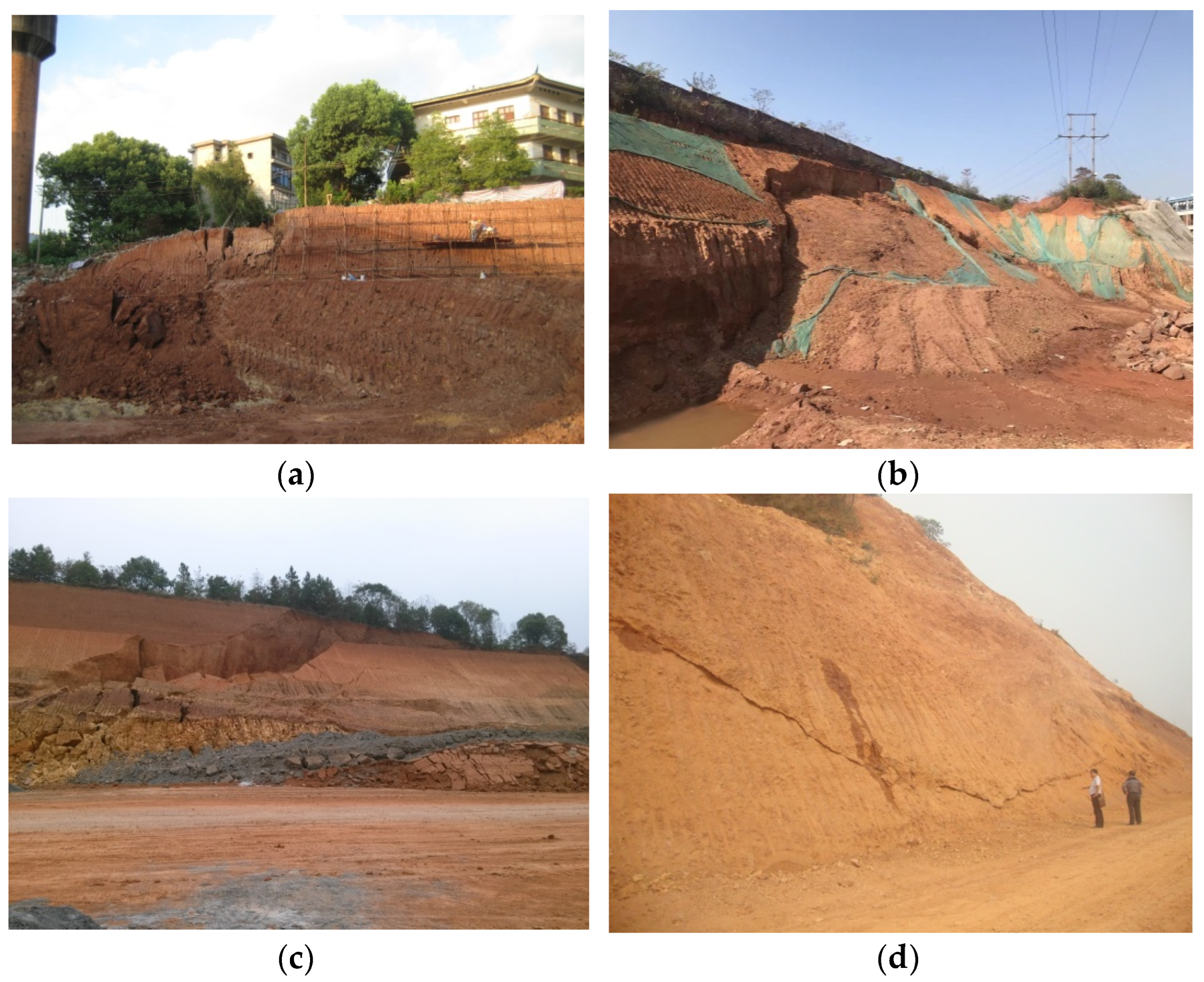
19] stated, interest is focused on the long-term stability of cutting slopes, and unfortunately, little attention has been paid to examining the abrupt, repeated failure induced by multi-excavation. It should be noted that slope construction methods must consider measures that will avoid immediate and sudden failure as well as protect the slope for the long term, unless the slope is built for short-term use only. Regrettably, as in the construction process of most retaining structures, the conventional philosophy of setting retaining structures after excavation makes the construction of the slope last a long time, which provides convenience for cut instability due to multi-excavation or other triggers (see
Figure 2).
Figure 2a shows a small landslide caused by the vibration of anchor hole construction machinery,
Figure 2b,c shows small and medium landslides caused by the decrease in soil strength due to rain infiltration, and
Figure 2d shows a sliding surface exposed on the cut slope surface due to excavation unloading.
Considering that the stability of the cutting slope at the end of excavation may be the key design condition affecting the temporary stability and permanent stability of the cutting slope, especially under the condition that the original slope surface is close to the design slope surface after excavation, this paper first puts forward a new lattice beam technique with anchors pre-set from the original slope surface to the target area (behind the cutting surface) before excavation, and its construction process is briefly introduced. Secondly, in order to verify the effectiveness of this idea in ensuring the temporary stability of the slope in the process of multiple excavations, an ideal dry homogeneous hard clay slope with three rows of pre-set full-length grouting anchors was modeled in the numerical software FLAC3D, and the same model without anchors was used for comparison. Finally, various factors such as the factor of safety (FOS), the maximum shear strain increment (MSSI), and the displacement and axial force of the anchors during multi-excavation were examined to evaluate the performance of slopes under different excavation stages with and without pre-arranged anchors by FLAC3D.
2. Slope Anchoring System with Lattice Beam
2.1. Conventional Construction Procedures for Slope Anchoring with the Lattice Beam
After more than 40 years of engineering practice in China, the lattice beam made of reinforced concrete for slope reinforcement with anchors has developed into a mature engineering technology, and the general construction procedures are as follows:
- (1)
According to the design slope height and slope angle, soils and rocks are excavated by layer from top to bottom until the excavation is completed;
- (2)
Boreholes are drilled and anchors are inserted into the boreholes after cleaning the holes with a high-pressure air gun. Then, the annulus around the anchors is filled with grout from the cutting slope surface;
- (3)
After the grout is cured to the predetermined strength, on the design slope surface, the reinforcement cages are set crosswise at the anchor heads and reliably connected to the individual anchor head (e.g., welding, bearing plate, and locking nut);
- (4)
The formworks are then installed on the cutting slope surface outside of the reinforcement cages, and the concrete is cast in the formworks to form the lattice beam.
In China, the lattice beam is a reinforced concrete frame beam structure that is mainly made of concrete with compressive strength no less than 25 MPa (C25), a cross-sectional beam area no less than b × h = 250 mm × 300 mm, and a distance between adjacent beams in both directions of no less than 4.0 m.
As a lightweight and flexible facing element, the lattice beam is set immediately on the exposed slope surface to connect with each anchor head to take full advantage of the high tensile strength of the anchors and address the global and local stability of the design slope for the long term.
2.2. Novel Construction Approach for a Lattice Beam with Pre-Arranged Anchors
The traditional construction method of lattice beams with anchors makes the cutting surface of the slope open for a long time, thus increasing the chance of slope instability during construction. In order to lower the probability and the scale of design slope failure during construction, especially during multi-excavation, a new slope reinforcement technique using a lattice beam with pre-arranged fully-grouted anchors was proposed and the construction processes are as follows:
- (1)
The range of the proposed excavation according to the requirements of land use, designed slope angle, and property line constraints is determined (see
Figure 3a);
- (2)
In reference to the original slope surface, holes are drilled at a nearly horizontal angle into the design slope, anchors are inserted into the holes of the designed target zone, and then the annuluses around the anchors are filled with grout by the grouting pipe after hole cleaning (see
Figure 3b);
- (3)
After the grout is cured to a predetermined strength, the proposed zone is cut by layer from top to bottom quickly, using excavators and exposing the design slope surface (see
Figure 3c);
- (4)
On the cutting slope surface, the reinforcement cages are set crosswise at the anchor heads and reliably connected with individual anchor heads at the intersections of the reinforcement cages. Then, the formworks are set out of the steel cages and the concrete is cast to form the lattice beam (see
Figure 3d).
During multi-excavation, the high tensile strength of the anchors pre-set into the design slope makes it possible to prevent excessive deformations and restrain downward movements. After the excavations, the lattice beam installed on the cutting slope surface and the anchors pre-set into the design slope act together as an anchorage system to reinforce the permanent stability of the design slope. Thus, this construction approach can take into account both the temporary and permanent stability of the slope and has the advantage of closing the slope surface quickly after excavations. During construction, the anchors pre-set into the design slope are used as temporary supporting components and remain stable during cutting for a reasonable time span, and, after the installation of the lattice beam on the design slope surface, the pre-arranging anchors become part of the permanent retaining structure and will work together with the lattice beam to retain the cutting stability for the long-term.
3. Numerical Analysis with FLAC3D
3.1. Idealized Model and Process
From a practical point of view, this new technology proposed in this paper is suitable for the reinforcement of various kinds of rock and soil slopes, in view of the fact that the projects in which the authors are involved in are clay slopes. In order to verify the effectiveness of the pre-setting anchors to improve the short-term cut stability during excavations, two idealized models of dry homogeneous hard clay mountainous slopes with anchors set in advance (model 1) and without anchors (model 2) are established in the finite difference code, FLAC3D.
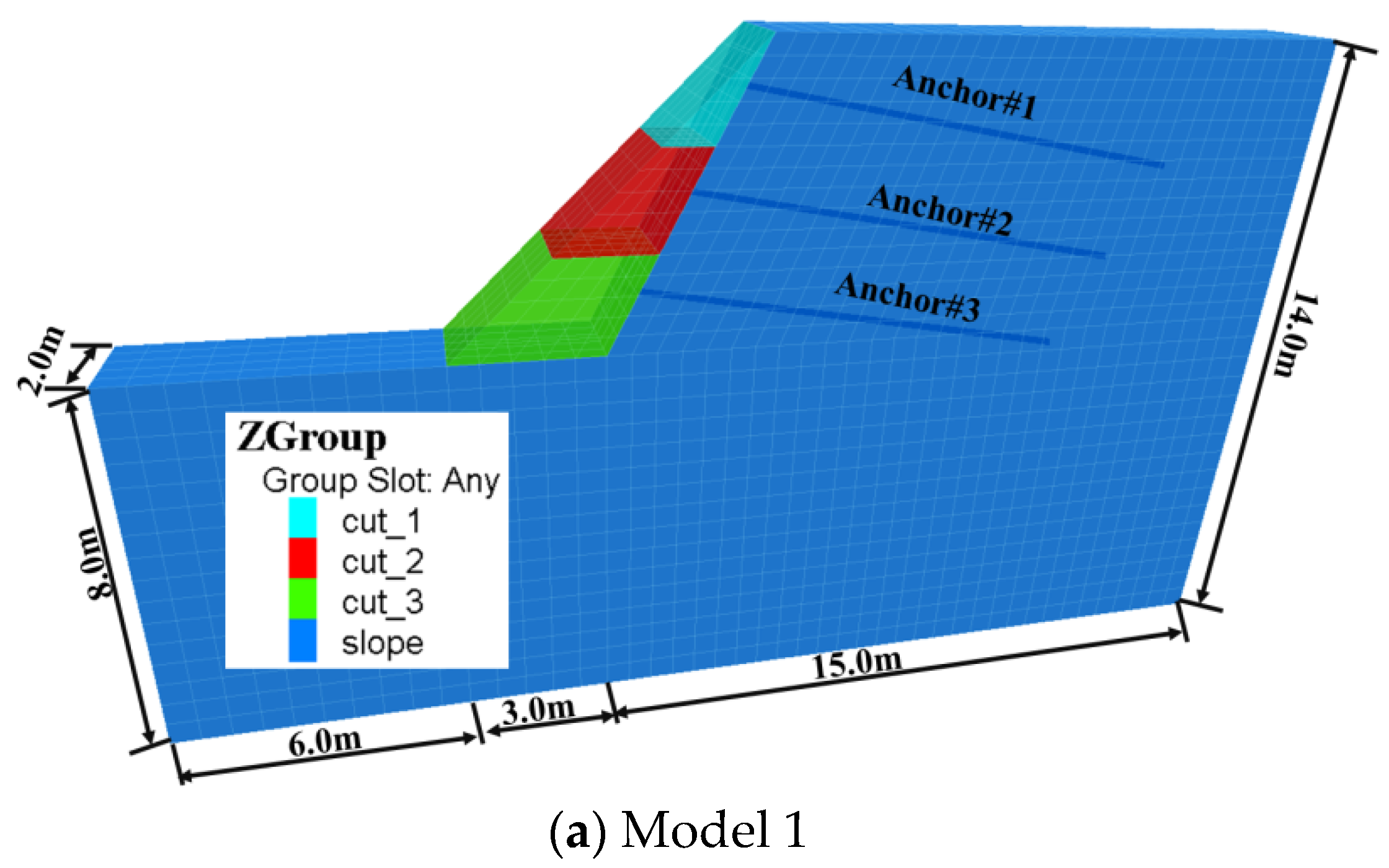
The original ground model before excavations has a height of 6 m and is 2 m in length along the slope strike with a 45° (1H:1V) slope angle. In practice, the excavation steps or excavation height generally corresponds to the layers or the vertical spacing of the anchors, so the design slope angle is about 63.4° (2H:1V) after three equal-height excavations from top to bottom in FLAC
3D. Boundary conditions can affect computed factor of safety result in three-dimensional stability analysis of slope via continuum-mechanics-based solution [
20], and the boundary conditions of the original ground model in this paper satisfy the following constraints: (1) the displacements of the bottom are completely fixed; (2) the horizontal displacement of the left and right boundary is limited; (3) no displacement is allowed along the slope strike direction; and (4) the top boundary is free to move. The distance between the front boundary (and the back boundary) of the calculation model and the anchors pre-set in model 1 is 1 m, so the influence of the boundaries, especially the front boundary and the back boundary, on the anchors can be ignored.
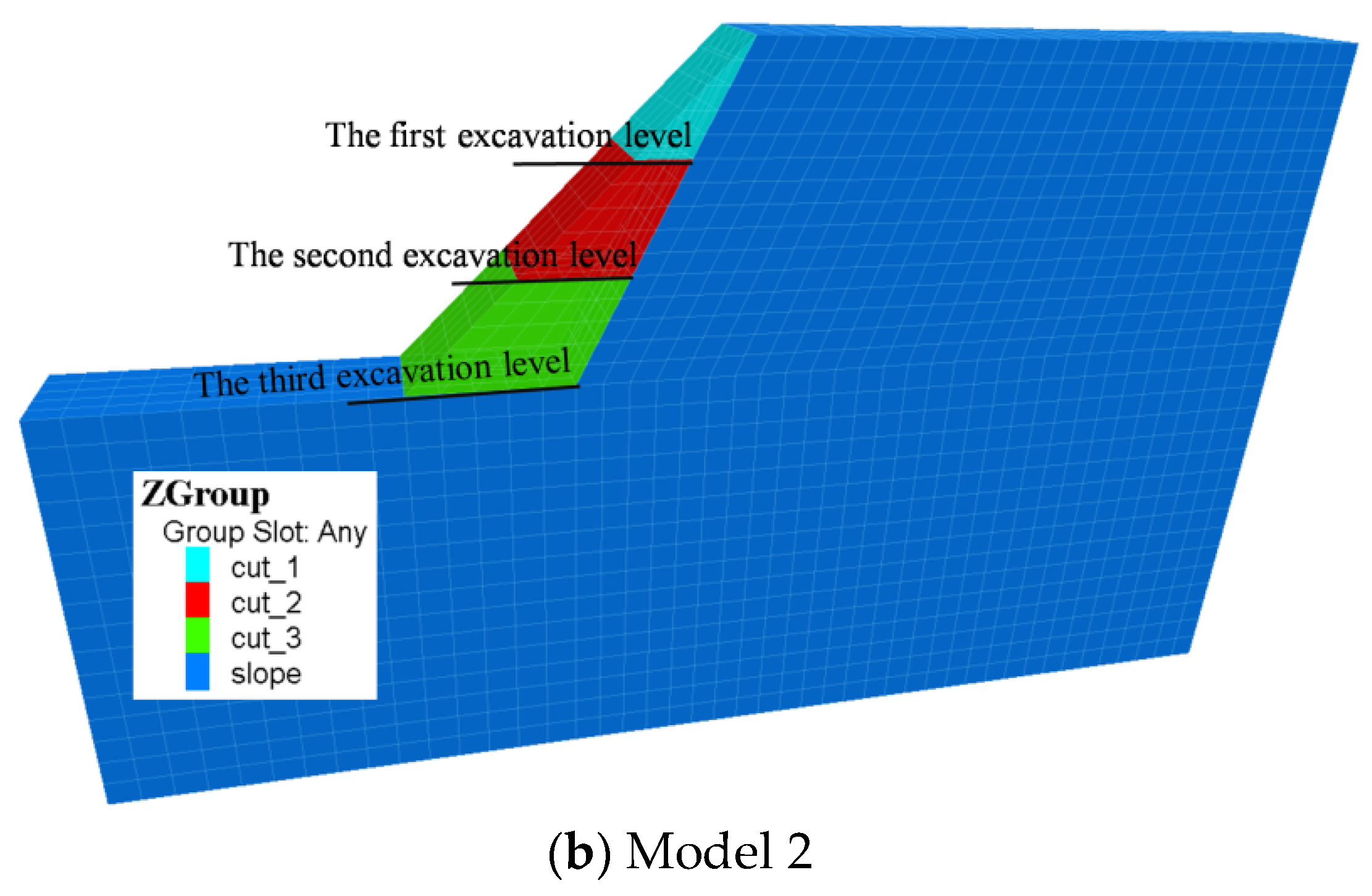
There are 7842 grid nodes and 6175 zones in each calculation model. From the slope crest to the slope toe, three rows of fully-grouted anchors with a vertical and horizontal spacing of 2 m from center to center are set in advance in the calculation model 1 (see
Figure 4a) from the original slope surface. In contrast, calculation model 2, without anchors, has the same geometric excavation condition and physical features as calculation model 1 also established in FLAC
3D (see
Figure 4b). Then, the first excavation (cut_1), the second excavation (cut_2), and the third excavation (cut_3) are conducted in turn in FLAC
3D for comparative analysis to examine the function of anchors set in advance for the reinforcement of cut stability during multi-excavation. As shown in
Table 1, the calculation flows for both models included the following states:
3.2. Constitutive Model and Parameters of Materials
This study aims at a kind of semi-solid hard clay slope from Hengyang City, Hunan Province, China. The original slope model is considered a perfectly-elastic plastic material and its mechanical behavior is controlled by the Mohr–Coulomb criterion. The physical and mechanical parameters involved in the calculations can be seen in
Table 2.
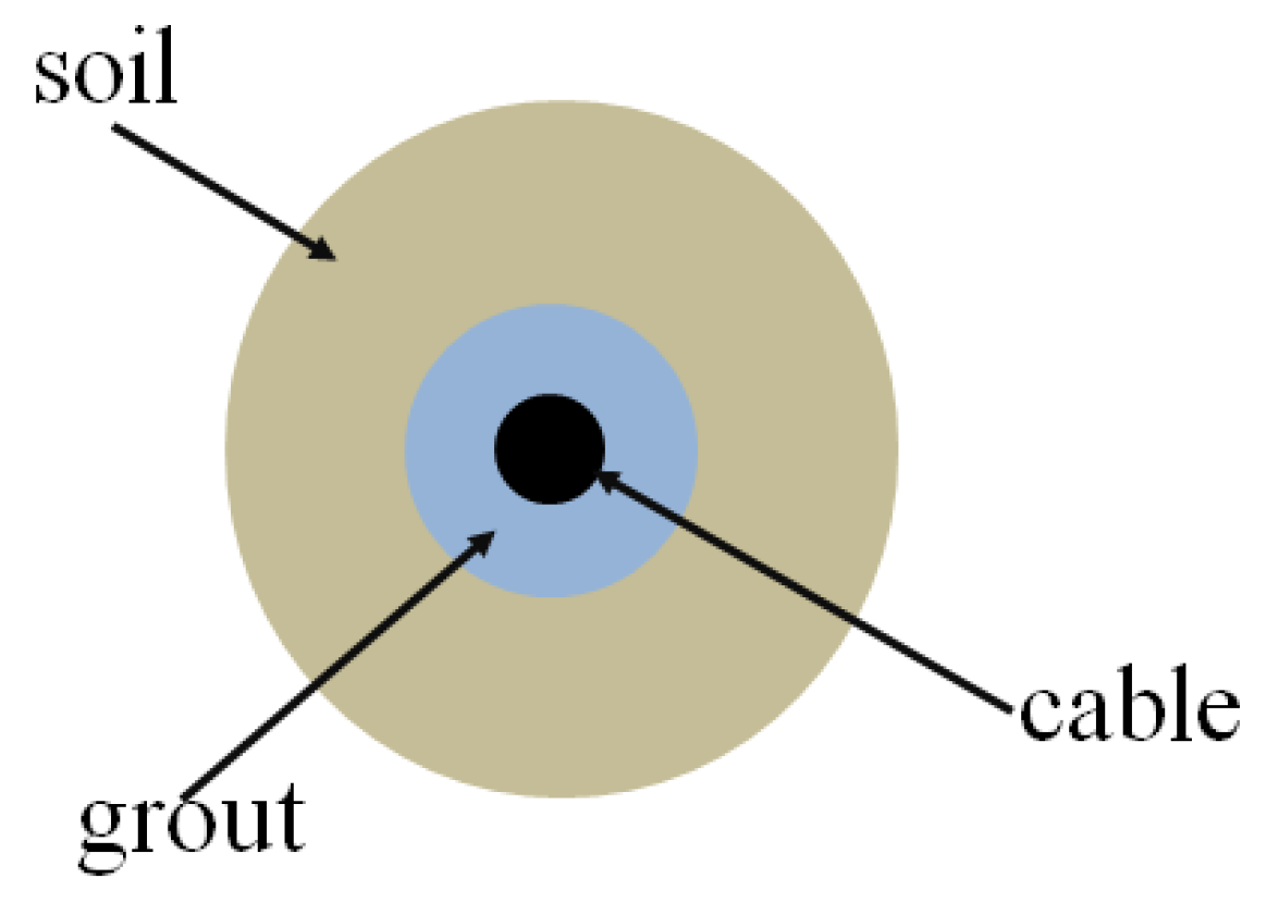
When the bending effects are ignored, the anchors pre-set in model 1 can be mimicked by the “cable element” embedded in FLAC
3D. The cable element is a perfectly-elastic plastic material that can yield under the action of compression or tension but cannot bear the bending moment. By setting the properties of the grout, the axial forces can be produced along the full length of the anchors when the soil element moves relative to the cable elements. The grouted cable elements also show perfectly-elastic plastic behavior, and their mechanical response is controlled by stresses. In summary, the mechanical responses of the cable-grout-soil system are determined by the geometry and material properties of the cable element and grout body. The working behavior of the cable-grout-soil system can be represented by the model in
Figure 5 and can be described numerically by the following two categories: (1) cross-sectional area (
A), Young’s modulus (
E), compressive strength (
Fc), and tensile strength (
Ft) of the cable element (steel bar); (2) grout exposed perimeter (
pg), grout cohesive strength (
cg), grout friction angle (
φg), and grout shear stiffness (
kg).
In model 1, the diameter of the boreholes is 150 mm. The anchors planted in the boreholes in advance are hot-rolled ribbed bars with a yield strength of 400 MPa (HRB400), and the pre-setting anchors are all 10 m in length with an inclination angle 10°. Cement mortar with a compressive strength of 30 MPa is used as the bonded material between the anchor and borehole wall. Except for grout shear stiffness (
kg), other parameters of the cable-grout-soil system can be found in design standards or textbooks easily; a reasonable estimation of
kg is provided in FLAC
3D as Equation (1) [
21].
where
G is the shear modulus of grout material and is equal to 9 GPa;
t is the annulus thickness of grout around the anchor and is equal to 61 mm; and
D is the diameter of cable element (HRB400 steel bar) and equals 28 mm. The parameters of the cable-grout-soil system used in calculation model 1 are listed in
Table 3.
3.3. Selection of Mechanical Responses during Excavations
The factor of safety (FOS) is one of the most direct indicators for the overall stability evaluation of natural or engineering slopes, and the calculation of FOS is realized based on the strength reduction method (SRM) implemented in FLAC3D by the “solve FOS” command.
In SRM, the shear strength parameters of the Mohr–Coulomb material are reduced in accordance with Equations (2) and (3).
where
c and
φ are cohesion and friction angle, respectively, and
ctrial and
φtrial are the reduced shear strength parameters used in the calculation. Through a series of iterations, the cohesion
c and the friction angle
φ are progressively reduced by different reduction factors,
Ftrial, until the slope gradually reaches a state of limiting equilibrium. At this time, the reduction factor,
Ftrail, is equivalent to the FOS of the slope, and, in other words, the FOS is the ratio of the soil’s initial shear strength to the reduced shear strength at a limited equilibrium state. By means of an SRM code implemented in FLAC
3D, a bracketing approach similar to that proposed by Dawson [
23] was used for slope stability analysis.
In addition to the FOS, the MSSI can also reflect whether the slope has a through sliding surface in the process of excavations; the appearance of a through sliding surface indicates that the slope is in a state of limited equilibrium. At the same time, the development of slope displacement under the influence of unloading and gravity forces in the process of excavations can also indirectly reflect the stability of the slope to a certain extent.
Therefore, in this paper, the FOS, MSSI, and slope displacement are used as comparative indexes to analyze the stability of the two models at the same excavation stage to verify whether the anchors pre-set in model 1 play a positive role in slope stability during excavations.
For model 1, because the anchors are arranged in the slope in advance, there will be a complex interaction between the pre-arranged anchors and the slope soil during multi-excavation. Due to the free surface formed by excavations and the excavation unloading, the stress redistribution of the slope is accompanied by the development of slope deformation relative to the pre-arranged anchors. The anchors pre-set in the slope gradually play a role of restraining the slope deformation in the process of excavations, which makes the anchors produce axial forces during multi-excavation. In this regard, the process of axial force development on the anchors pre-set in the design slope is also the process of strengthening the slope soil mass. Thus, the discussion on the mobilization process of the axial forces on the anchors pre-set in model 1 can also provide favorable evidence for understanding the mechanism of reinforcement of the cutting slope by anchors pre-set in the design slope from the original slope surface. At last, in the process of numerical simulation for model 1, the axial forces at the middle position of the “cable elements” are taken as representative values to draw the curves of axial forces along the anchor length in order to reveal the development laws of the axial force for the pre-set anchors in the slope with excavations.
4. Discussion of Numerical Results
4.1. FOS
The global FOSs for both models at different stages can be easily obtained by FLAC
3D (see
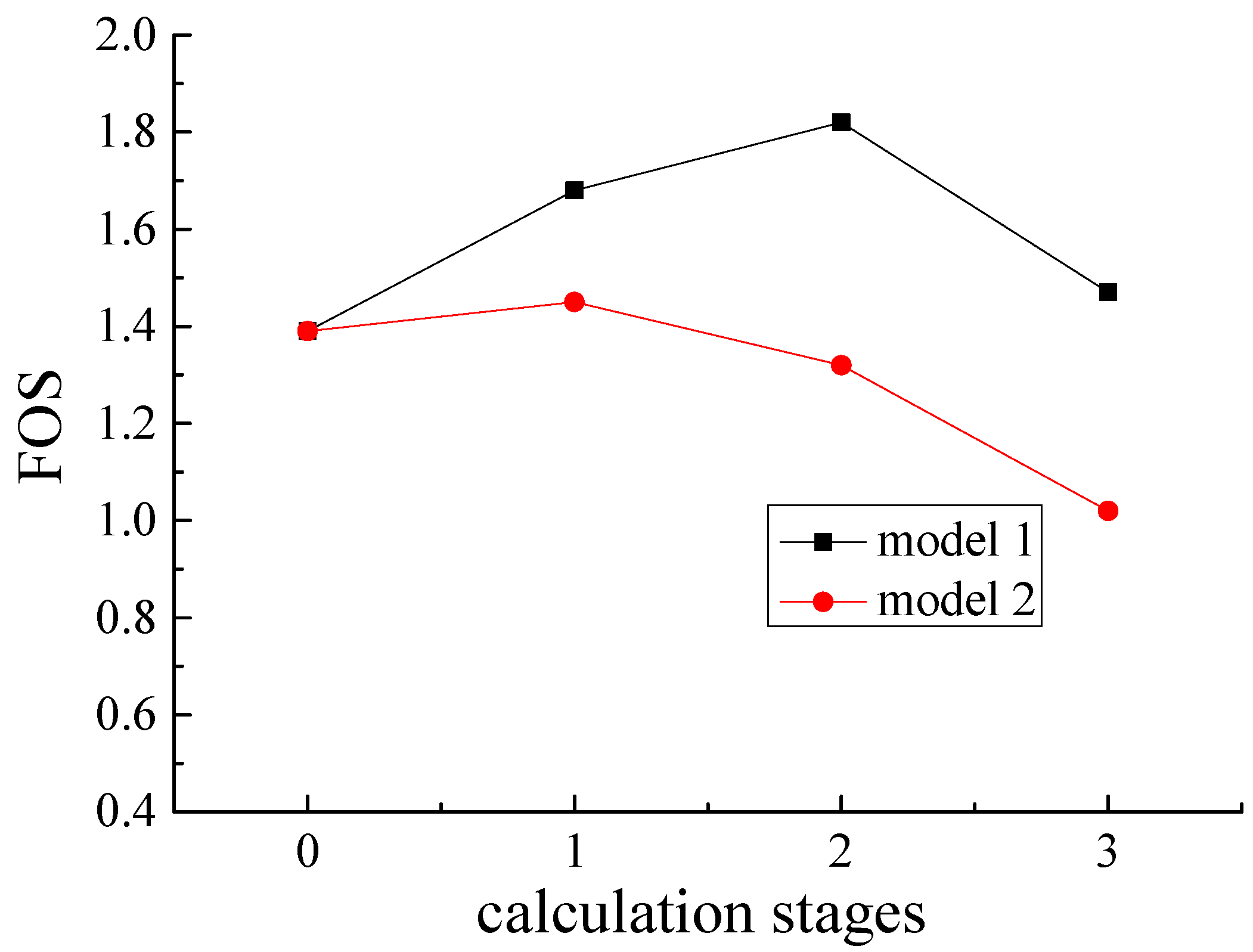
Figure 6).
Figure 6 shows that the curves of the FOS for both models have similar trends with excavations. The FOSs for both models are equal to 1.39 before excavations, and with excavations, the curves of the FOS show the characteristics of “increasing at first and then decreasing”. Specifically, the FOS of model 1 first increases from 1.39 before excavations to 1.68 after the first excavation, then further increases to the maximum value of 1.82 after the second excavation, and finally decreases to 1.47 after the third excavation; while the FOS of model 2 increases from 1.39 at stage 0 to the maximum value of 1.45 after the first excavation, then decreases to 1.32 after the second excavation, and finally decreases sharply to 1.02 after the final excavation. The development trend of the FOS for both models can be explained by considering that the excavations at the top could reduce the driving force so as to make the slope tend toward a more stable state, while the excavations of the toe could lower the resisting force so as to make the slope tend toward an unstable state.
Generally, the FOS of model 1 is higher, with a variation of 15.9–44.1%, than that of model 2 at each stage, which proved that the anchors set in the design slope in advance before excavations can effectively improve the temporary cut stability during multi-excavation. On the other hand, for model 2, multi-excavation according to the predetermined slope angle (2H:1V) from the top to bottom without reliable engineering measures may lead to cutting instability, especially after the final excavation. In addition, the maximum values of the FOS for both models in
Figure 6 do not appear at the same excavation condition, which can be further explained by the fact that the reinforcement effect of the pre-setting anchors on the slope depends upon and lags behind the slope deformation caused by excavation unloading.
4.2. MSSI
One of the most important tasks in slope stability analysis is the tracing of the slip surface as the appearance of a continuous slip surface in a slope can reflect that the slope is in an unstable state. As Singh [
24] stated, the stability of a slope can also be expressed in terms of the development of strains. Typically, various mechanical response parameters related to strain, such as plastic zone development [
25,
26], shear strain rate [
27,
28], and shear strain increment [
29,
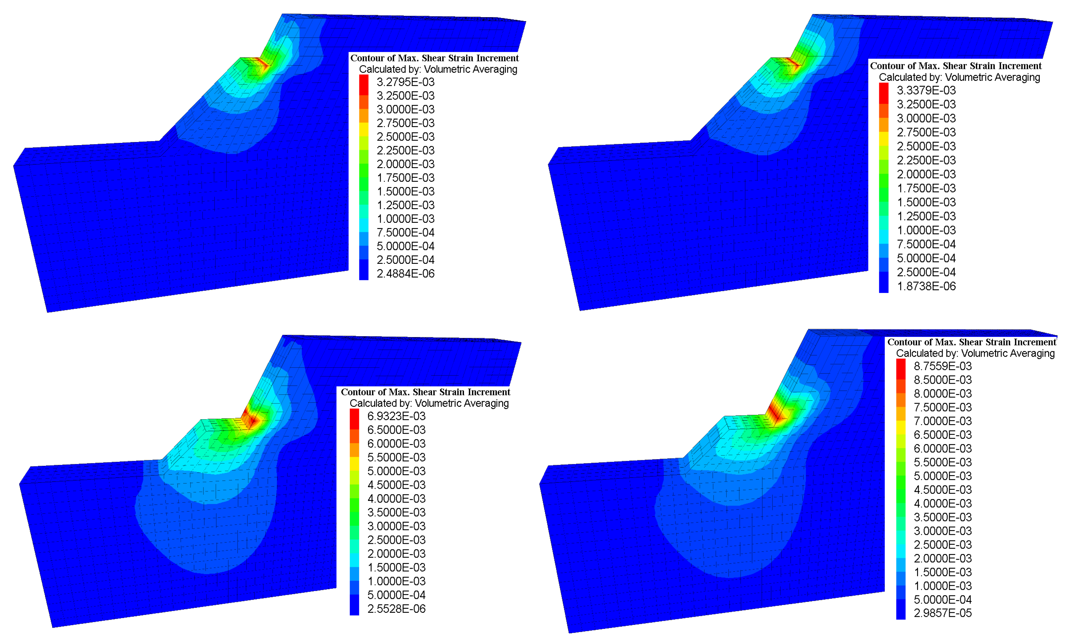
30], have been used to search the position of critical slip surfaces for a specific slope. In this paper, the MSSI is used to display the development and evolution of the potential slip surfaces of the two models under different excavation conditions (see
Figure 7). According to Mohr’s circle, between d
ε1 (the maximum principal strain increment) and d
ε3 (the minimum principal strain increment), the maximum shear strain increment value is d
γmax = |d
ε1 − d
ε3|, which is the diameter of Mohr’s circle.
Figure 7 shows the comparison of the developments and evolution of MSSIs for both models under different excavation stages. Due to the constraint effect of the anchors set in model 1 in advance, the contours of the MSSI show three-dimensional distribution characteristics, while the contours of the MSSI for model 2 without pre-arranged anchors show plane characteristics. Additionally, the MSSIs of both models gradually develop downward and appeared near the bench surfaces beneath each excavation level with multi-excavation.
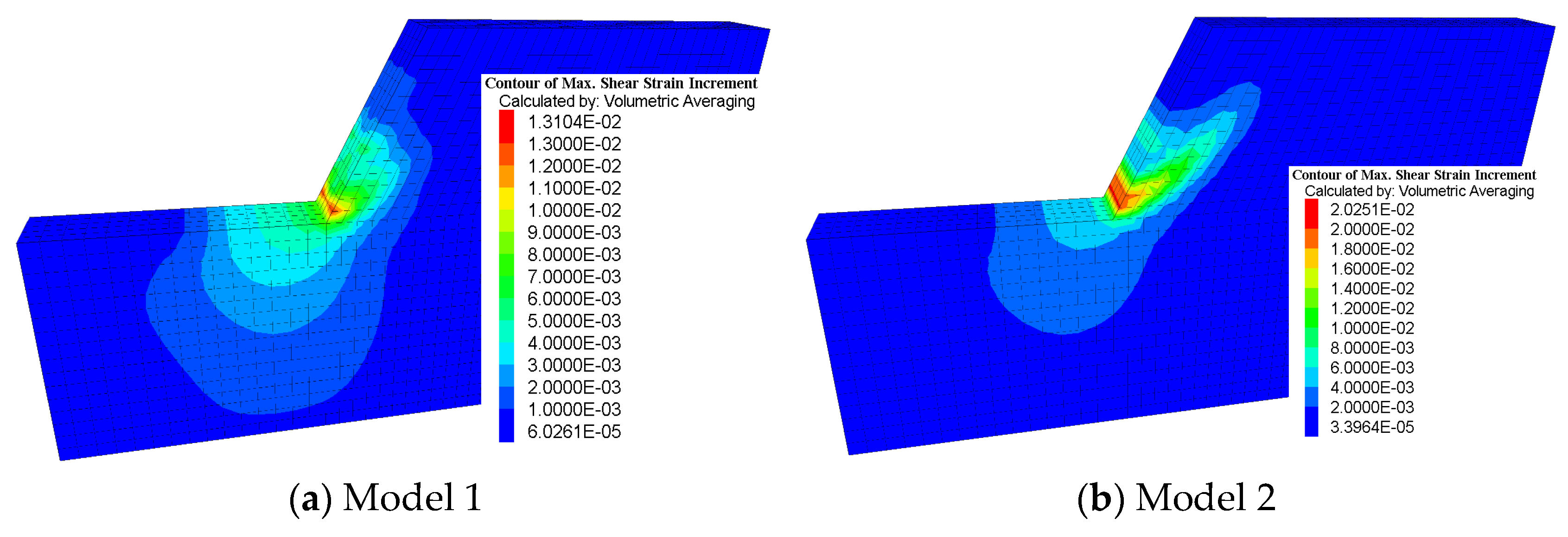
Both of the models have similar ranges and influence zones for the MSSI after the first and second excavation, but after the third excavation the ranges and influence zones for the MSSI are quite different and it is clearly evident that model 2 develops a circular failure with a higher MSSI along the failure surface. Model 1 does not show continuous sliding surfaces after each excavation which indicates that the cut stability during excavations can be guaranteed by the anchors set in advance. On the other hand, model 2 shows higher temporary stability after the first and second excavations, but after the third excavation, there is an obvious sliding surface extending from the toe to the crest of the cutting slope, indicating that the slope without temporary engineering measures is in a state of limit equilibrium and, at this time, the FOS equals 1.02. From the perspective of the development of the plastic zone, the contour of the shear plastic zones (see
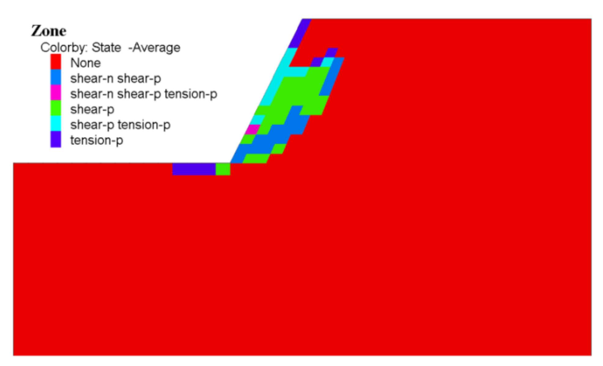
Figure 8) also shows that model 2 is in the limit equilibrium state after the final excavation, and the failure surface determined by the plastic zone, which represents the physical state of the elements, coincides well with the MSSI.
The comparative analysis of MSSI for both models under each stage shows that the anchors pre-set in the slope can effectively restrain the magnitude of the MSSI, change the distribution model of the MSSI, and ensure the temporary stability of the slope during multi-excavation, especially during the toe excavation.
4.3. Displacement
Most slopes have a tendency to slide during or after excavation, especially soil slopes. During excavations, these slopes usually undergo a long or short process of stress redistribution, and excavation unloading leads to stress release in the vicinity near the excavation surface. The stress balance of the original ground will be broken during excavations, and the stratum will spontaneously conduct stress adjustments to achieve a new balance. The process of stress adjustments is accompanied by the rotation of the principal stresses and the development of displacements. With multiple excavations, the number of displacements increases gradually, and the deformation influence area gradually moves away from the excavation surface into the depth of the slope until a significant sliding surface occurs behind the excavation surface. At this time, the displacements of soil elements near the sliding surface show a great difference in magnitude, resulting in a landslide (see
Figure 9), and the local stress state reaches a new equilibrium again.
In fact, as long as reliable temporary engineering measures are used, not all cutting slopes experience landslide during or after excavations before the completion of the retaining structure. However, the stress redistribution caused by excavations will inevitably be accompanied by large or small displacements, which can indirectly reflect the stability of the slope [
23].
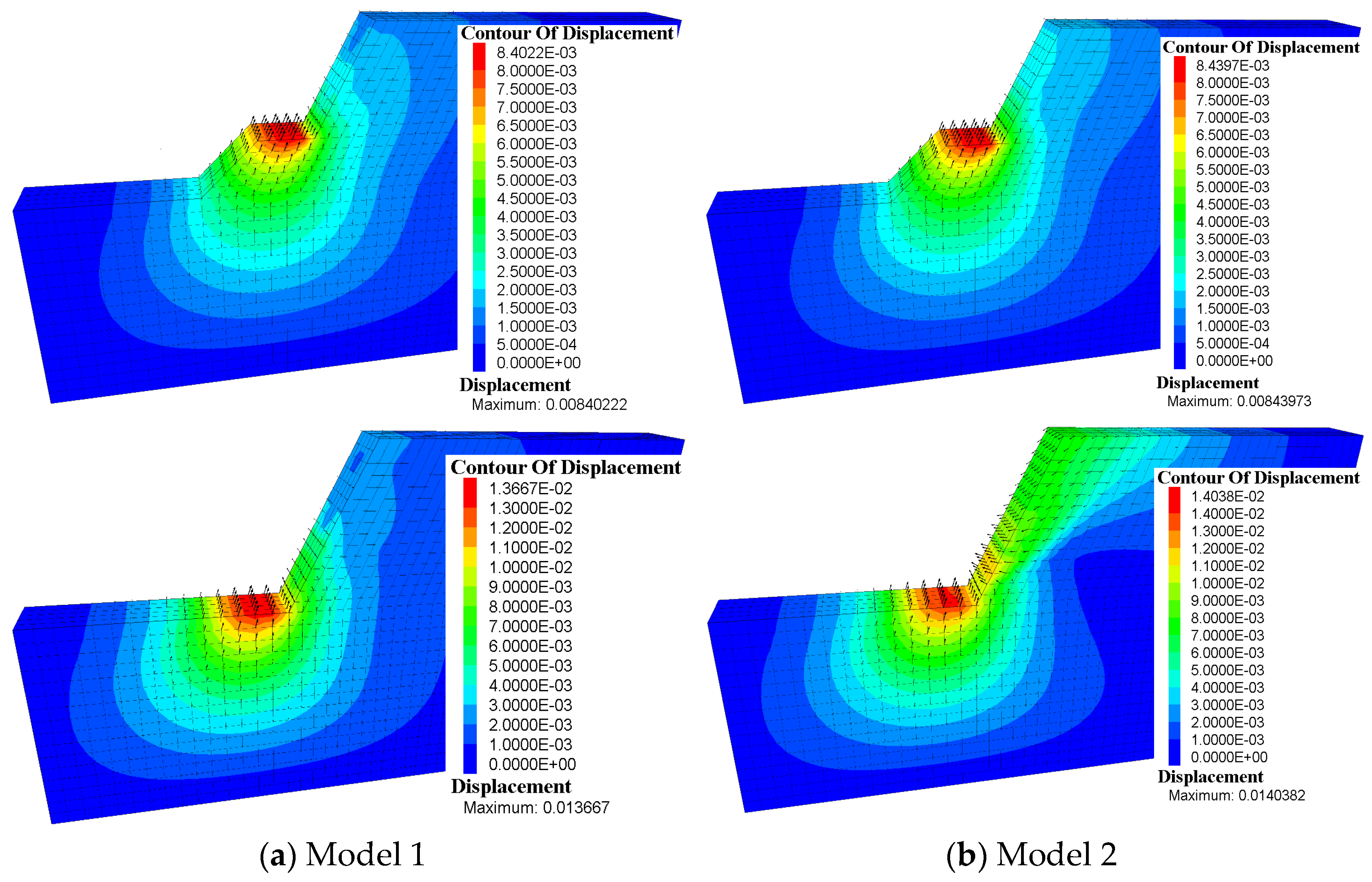
Figure 10 shows the total displacement contours and the total displacement vectors for model 1 and model 2 at different stages.
As can be seen from
Figure 10, due to the deformation constraint of the anchors set in advance in model 1, the total displacements of model 1 show three-dimensional characteristics, while the total displacements of model 2 without pre-set anchors show plane characteristics under different excavation conditions.
For model 1, with excavations, the total displacement amount increases gradually, and the influence range of the total displacement gradually shifts away from the excavation surface to the depth of the design slope. Due to the direct relief effect of excavations, the maximum total displacements appear near each excavation level and show an upward rebound deformation approximately parallel to the design slope surface. For the design slope surfaces above the excavation levels, due to the direct deformation constraint of the pre-set anchors, the deformations of the design slope surface are mainly characterized by outward and upward rebound deformation rather than the downward deformation caused by gravity forces. The description of the above displacement phenomena proves that the anchors pre-set in model 1 resist the influence of gravity to a certain extent and change the displacement distribution region of the design slope above the excavation levels.
For model 2, the maximum total displacement also increases gradually with the excavations and appears at the benches beneath each excavation level. Additionally, the maximum displacement near the excavation level also shows a rebound deformation approximately parallel to the design slope surface formed by multi-excavation. After the first and second excavations, the deformations of the soil behind the design slope surface are mainly characterized by an outward and upward rebound deformation, but after the third excavation, the deformation of the large-scale soil behind the design slope surface gradually changes from an upward rebound deformation to a downward deformation due to gravity forces.
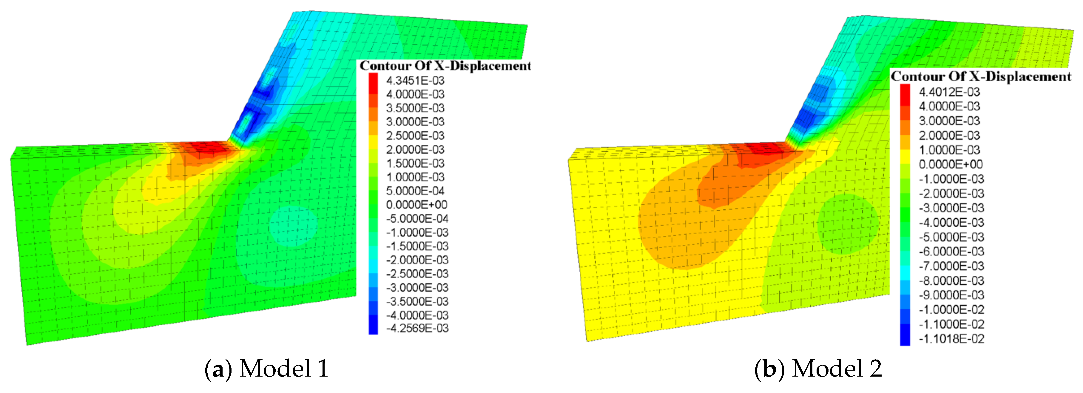
The comparative displacement analysis for model 1 and model 2 shows that the pre-set anchor has little effect on the amounts and the directions of the maximum total displacement beneath each excavation level but has a significant influence on the amounts and the directions of the total displacement behind the design slope surface exposed by multi-excavation. The difference in total displacement characteristics between the two models, especially after the last excavation, can be explained in that the pre-set anchors in model 1 indirectly change the characteristics of vertical displacement or even total displacement by directly restricting the horizontal displacement of the cutting slope above each excavation level due to the near-horizontal setting of the anchors (see
Figure 11).
Figure 11 shows that the maximum horizontal displacement of the cutting slope surface of model 1 is only about 38.6% of the maximum horizontal displacement of the cutting slope surface of model 2 after the third excavation.
4.4. Axial Force of Anchors
As can be seen in
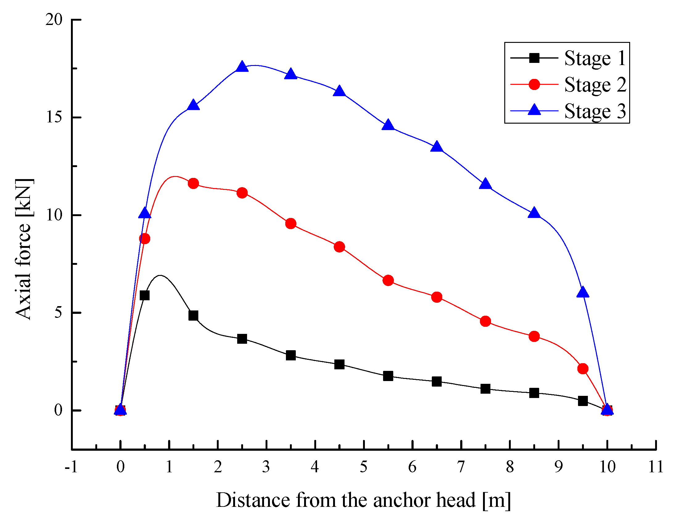
Figure 12, with excavations, the axial forces of anchor #1 are always in a tension state and the tension forces increase continuously with excavations. The position of the maximum axial forces shifts from near the design slope surface to the depth of the slope and the axial force distribution model finally develops into a typical “jujube core” distribution after the final excavation.
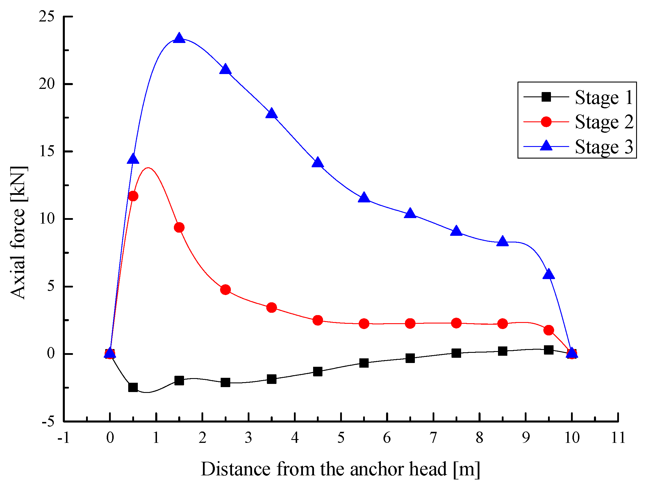
As seen in
Figure 13, the bench formed by cutting after the first excavation tends to move towards the design slope; anchor #2 is in a state of compression nearly along the full length. However, after the second excavation, the excavation unloading gradually puts anchor #2 in a tensile state, and after the third excavation, the axial tension force of anchor #2 increases further, and the position of the maximum force develops slowly to the depth of the slope during excavations. Due to the spatial effect near the toe of the design slope, the reinforcement effect of anchor #2 has not been brought into full play, so the axial force characteristics of anchor #2 develop into an abnormal “jujube core” distribution after the third excavation.
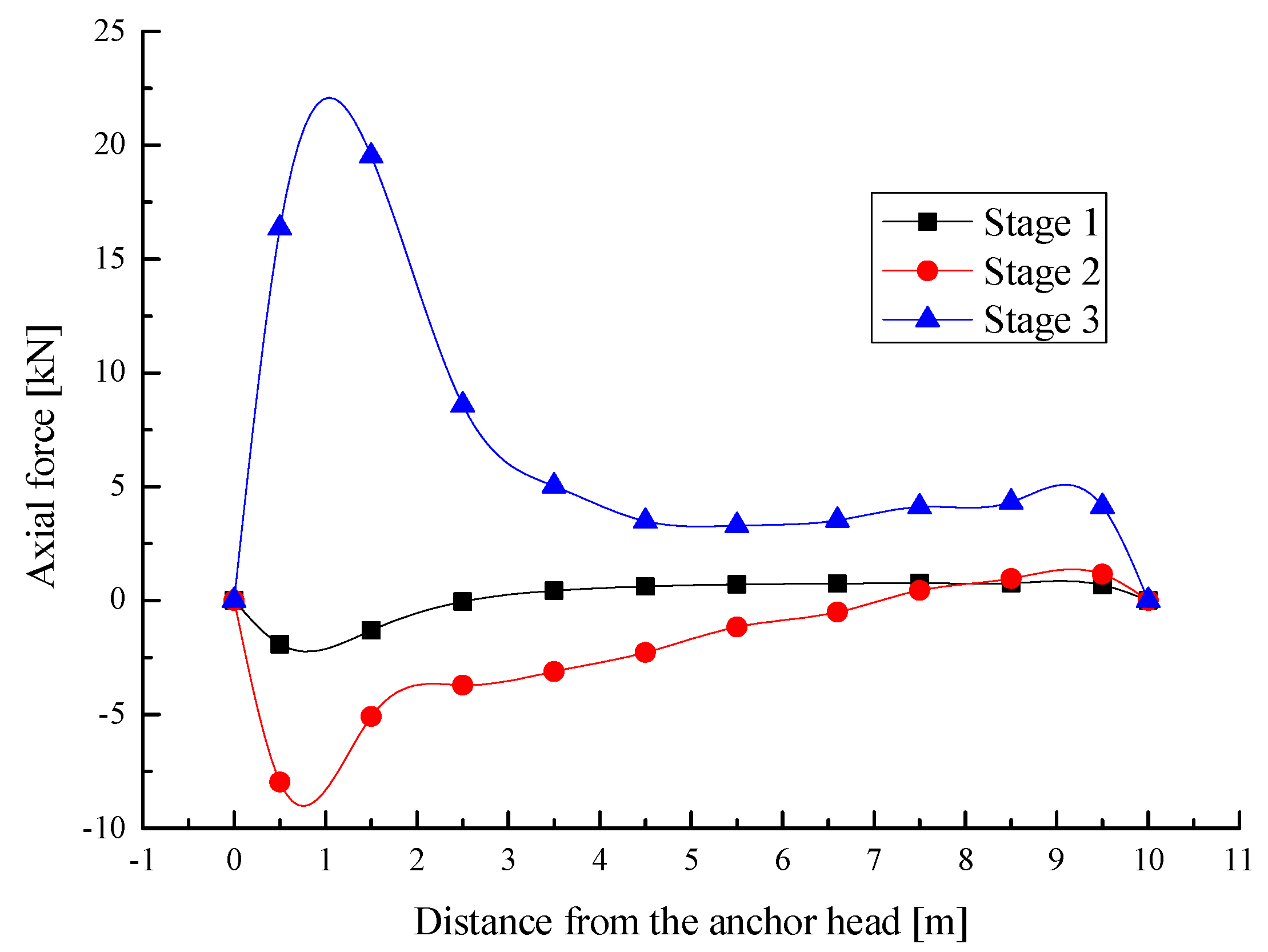
Anchor #3 is mainly under a compression state nearly along the full length after the first and second excavation; the axial compression forces increase gradually before the third excavation, and the maximum axial compression is mainly distributed near the design slope surface after the first and second excavation. After the third excavation, the axial force of anchor #3 changes from a compression into a tension state, and the positions of the maximum axial force appear near the design slope surface (see
Figure 14). Anchor #3 is more affected by the spatial effect of the slope toe than anchor #2, and the maximum axial force of anchor #3 is 16.3% less than that of anchor #2.
The comparative analysis of
Figure 12,
Figure 13 and
Figure 14 shows that the exertion of the axial forces of the anchors depends upon the amount and direction of soil displacement relative to anchors after each excavation. After the first excavation, the slope soil around anchor #1 moves outward relative to anchor #1, so anchor #1 is in a tension state, while anchor #2 and anchor #3 are in a compression state because the bench formed by the first excavation tends to move towards the design slope due to unloading. After the second excavation, the axial tension force of anchor #1 further develops, the axial force of anchor #2 changes from compression to tension, and the axial compression force of anchor #3 further increases. After the third excavation, the axial tension forces of anchor #1 and anchor #2 continue to develop, while anchor #3 transforms from a compression into a tension state gradually.
After the completion of excavations from top to bottom, the lattice beam will be set on the designed slope surface immediately and connected with each anchor head according to the construction process proposed in this paper. The lattice beam anchorage system with the designed slope will then work together to retain the design slope for the long term. Under service conditions, the axial forces of the anchors will be further developed due to the surcharge load and reduction in soil strength, and finally, the axial forces of each pre-setting anchor will be developed into a typical “jujube core” shape gradually.


