
The Criteria for Assessing the Safety of Buildings with a Reinforced Concrete Frame during an Earthquake after a Fire
Department of Reinforced Concrete and Stone Structures, National Research Moscow State Civil Engineering University, 26, Yaroslavskoye Shosse, 129337 Moscow, Russia
*
Authors to whom correspondence should be addressed.
Buildings 2022, 12(10), 1662; https://doi.org/10.3390/buildings12101662
Submission received: 1 September 2022
/
Revised: 20 September 2022
/
Accepted: 30 September 2022
/
Published: 12 October 2022
(This article belongs to the Special Issue Safety and Optimization of Building Structures)
Abstract
:In the paper, there was researched sensitivity of the criteria for evaluation of seismic resistance of reinforced structures (modes and frequencies of oscillations, displacements, and strains) in relation to various position of fire impact as exemplified by three-span five-storey reinforced concrete space frame. The relevance of the study is justified, the degree of the problem’s development is grounded. There were analyzed the main lines of the research connected with experimental and numerical testing of both discrete structures and full-sized buildings. Numerical analysis was conducted by means of the software complex Ansys, the linear-spectral method was used. Fire impact is simulated by means of damages to reinforced concrete members in one of the building’s units. 16 variants of points of fire outbreak were considered. According to the calculation results, it was stated that for all the variants of fire outbreak frequencies of self-oscillations for reinforced concrete frames after the fire had been found lower than for the non-damaged frame. The modal analysis has shown that the type of longitudinal and bending oscillations had undergone changes. The maximum amplitude of frames’ oscillations after the fire was found insignificantly lower than for the non-damaged frame. Within the floor of fire outbreak location, the displacement increased immensely so that led to failure to comply with the value of inter-floor shifts and the increase of the 2nd order effects. Redistribution of bending moments in reinforced concrete framings was observed. The loading in damaged members decreased due to the members’ strain capacity whereas the extra loading is added to the adjacent members. If compared with the case of the frame non-damaged by fire, overloading of columns can reach up to 20%. Conceptual description of fracture behavior of the frame is outlined assuming its non-linear behavior. The possible lines of further development are set for the methods of seismic analysis of the buildings with reinforced concrete frame after the event of fire.
1. Introduction
Progressive increase in number of floors in buildings and development density of modern cities hinders the access to the points of fire outbreak for fire-fighting crews and timely fire suppression.
While designing reinforced concrete structures, it is necessary to make provision for safety margin with the purpose of ensuring structure’s fire resistance and fire durability specified by the current codes and regulations.
It is understood that fire is considered one of the most problematic scenarios, thus, taking steps for provision of adequate fire safety is of paramount importance. Fire resistance is usually determined as a period of time when the structural integrity of a member exposed to fire is retained to withstand the applied loading. However, the task is not only to provide time for safe evacuation of people but to reduce the probability of any fire [1].
Fire poses specific hazard for buildings and structures in seismically dangerous areas [2,3,4,5,6]. Here, two different combinations of impacts could be identified: fire after earthquake and earthquake after fire.
Seismic characteristics of reinforced concrete structures after fire were studied in the works of [7,8,9,10,11,12,13,14].
There are two real scenarios of earthquake formation after the fire:
- (1)
- In a building located in a seismically dangerous area, initially fire breaks out and 55 then, in the course of maintenance, an earthquake occurs.
- (2)
- After an earthquake, fire breaks out and after a while a building is exposed to aftershocks.
In an earthquake, one out of four fires is caused by a gas leak.
An earthquake in Kobe (Japan) on 16 June 1991, where a fire followed the main earthquake. During the Tashkent earthquake (Uzbekistan) on 26 April 1966, a large number of fires were observed.
Fires arise as a result of the increased density of the city’s construction, where, during an earthquake, a fire quickly spreads to neighboring buildings.
Nowadays, due to insufficient development of the issue and the lack of illustrative engineering methods to be introduced into design practice, regulative documents do not contain exact recommendations on accounting for these combinations of possible scenarios.
The main lines of research related to the issue of seismic resistance of reinforced concrete structures after the fire include experimental and numerical tests of discrete members of structures and their joints.
The most part of the works is dedicated to experimental loading of reinforced concrete columns exposed to low-cycle loading.
The methodology of experimental identification of seismic characteristics for reinforced concrete structures after fire usually comprises sequential fire and low-cycle dynamic and quasi-static tests.
In [15], there was implemented experimental and numerical study of a bended reinforced concrete member exposed to two concentrated loads. Then the specimen was exposed to fire action in order to determine the impact of formed cracks on the change of heat propagation inside the cross section. The results have shown that insignificant cracking would not lead to considerable change of heat penetration inside the cross section.
In [16], steel structures exposed to fire after the earthquake were studied. The analysis of both earthquake and fire was implemented. The methodology for evaluating the features of buildings exposed to earthquakes was developed. The levels of fire resistance were proposed for various fire conditions.
The study of fire resistance of reinforced concrete frame damaged by earthquake was described in the [17].
While carrying out fire tests, reinforced concrete specimens were placed in the furnace. The heating of specimens is done under the dependency of the corresponding standard curve in compliance with ISO 834.
The duration of standard fire is usually divisible by 30 min, i.e., 30, 60, 90, 120 min, etc. This corresponds to assignable fire endurance of building structures.
The serious shortcoming of many existing experiments is the lack of static loading during fire tests. Cracks and chips that appear during high-temperature heating of concrete develop more intensely at the presence of vertical static loading. This leads to a greater exacerbation of mechanical properties of reinforced concrete columns [18].
This phenomenon was described in the paper [19] dedicated to the study of reinforced concrete pylons performance. During fire tests, pylons were exposed to axial impact of permanent intensity. It was revealed that the presence of vertical loading during the fire does not have a considerable impact on seismic stability and stiffness but lowers the ability of a pylon to dissipate the energy at low-cycle loading that caused by the presence of significant initial damages.
While determining seismic features of reinforced concrete specimens experimentally after the fire, the further step is testing on low-cycle horizontal loading. Horizontal low-cycle loading is usually assumed under the scheme recommended in the standard ACI 374.2R-13 [20]. Lateral loading was gradually increased from the zero value after each second cycle up to the fracture. During fire tests, damages are developing in concrete cross-section. At the initial stage, cracks caused by temperature deformations are forming. Then, at specific spots chipping and flaking of concrete occurs due to pore pressure elevation. These defects significantly lower seismic characteristics of columns.
The following four stages of fracturing reinforced concrete columns were identified under the conditions of low-cycle loading [9]: normal cracks formation, destruction of a concrete protective layer, destruction of the central part of concrete cross section, final failure caused by the stability loss of longitudinal reinforcement.
This type of failure mechanisms is called bending mechanism. Apart from bending mechanism, shear and compressive-shear fracture mechanisms are identified [21]. Fire action on reinforced concrete columns could alter their fracture mechanism.
For instance, the work [22] stated that fire event before the earthquake has an impact not only on bearing capacity, stress strain and damping properties of reinforced concrete one-floor and one-span framework but also on its fracture mechanism when the loss of bearing capacity occurs along the column before formation of plastic centroids in beams.
Similar results have been obtained while testing the separate unit of multi-storied reinforced concrete frame [21]. The frame designed according to the concept “Strong Column—Weak Beam after the fire experiences the loss of bearing capacity due to column fracture that is of shear type, without formation of plastic centroid in a beam.
Contraction cracks in concrete arising during fire tests reduce the rate of stiffness degradation for columns as brittle failure related to sudden loss of stiffness is eliminated.
The length of plastic strains (plastic centroids) of columns grows when the duration of fire action exceeds 30 min. This effect should be taken into account during the design stage providing the measures for augmenting plasticity of these zones, for instance, by placing of shear reinforcement.
In the paper [10], there was studied the influence of the number of column’s heated sides on its seismic response. It was revealed that when the number of heated sides is reduced, the maximum temperature of the concrete core is decreased. As a sequence, along with that bearing capacity and total dissipated energy are growing.
Application of steel and concrete composite cross-sections, whereas the metal section, for example, I-joist is installed in the central part of the cross-section, heated at a lesser extent during the fire is considered a rather effective method of enhancement seismic properties of columns after the fire [11]. Owing to the steel core, steel and concrete composite column has much higher plastic properties after the fire.
While solving the issue of allowance given for seismic loading after the fire, the number of researchers has applied the method of numerical modelling apart from field experiments. Development of modern software complexes such as SAFIR, ANSYS, SAP2000, etc. offers the scope for allowance given for combinations of specific impacts.
In the study [12], there were outlined the results of numerical modelling for two columns with axial loading and horizontal quasi-static loading. The results of analysis have shown that main seismic characteristics, namely ultimate shear loading and plasticity, are reduced at a greater extent as the result of fire. Similar results are observed at numerical calculations of reinforced concrete walls [19] on the impact of low-cycle loading. It was stated that the maximum rate of seismic parameters degradation occurs when the duration of fire ranges within 0–30 min.
In order to investigate the regularities of altering damping properties of reinforced concrete columns exposed to fire action of various duration, numerical modeling in the software complex Ansys was carried out [23]. From the results of numerical modelling, it was derived that the total energy dissipated by a column as well as the width of hysteresis looping are reduced with the increase in combustion time. The coefficient of hysteresis damping at various fire duration could be either higher or lower its initial value.
As plastic work of column-beam joints is mainly determined by seismic response of the framework and the mechanism of its failure, many authors have dedicated their works to the study of the analysis of framework joints exposed to low-cycle loading after the fire [24,25].
For the structures damaged by fire, there are considered the methods of reinforcement and augmentation of plasticity to enable them to withstand seismic loading [24,26,27].
In the paper [28], non-linear dynamic analysis of five-storied building after the fire event is conducted. There were proposed 5 scenarios of inflammation at fire impact of variable duration at different floors.
The purpose of the present work is the study of sensitivity criteria for evaluation of seismic resistance of reinforced concrete structures to various position of fire impact for building’s plan and height. The study is exemplified by three-span five-storied reinforced concrete spatial frame. As a basis, there was assumed linear-spectral method of analysis in numerical statement carried out in the software complex ANSYS [29].
2. Materials and Methods
2.1. Design Scheme
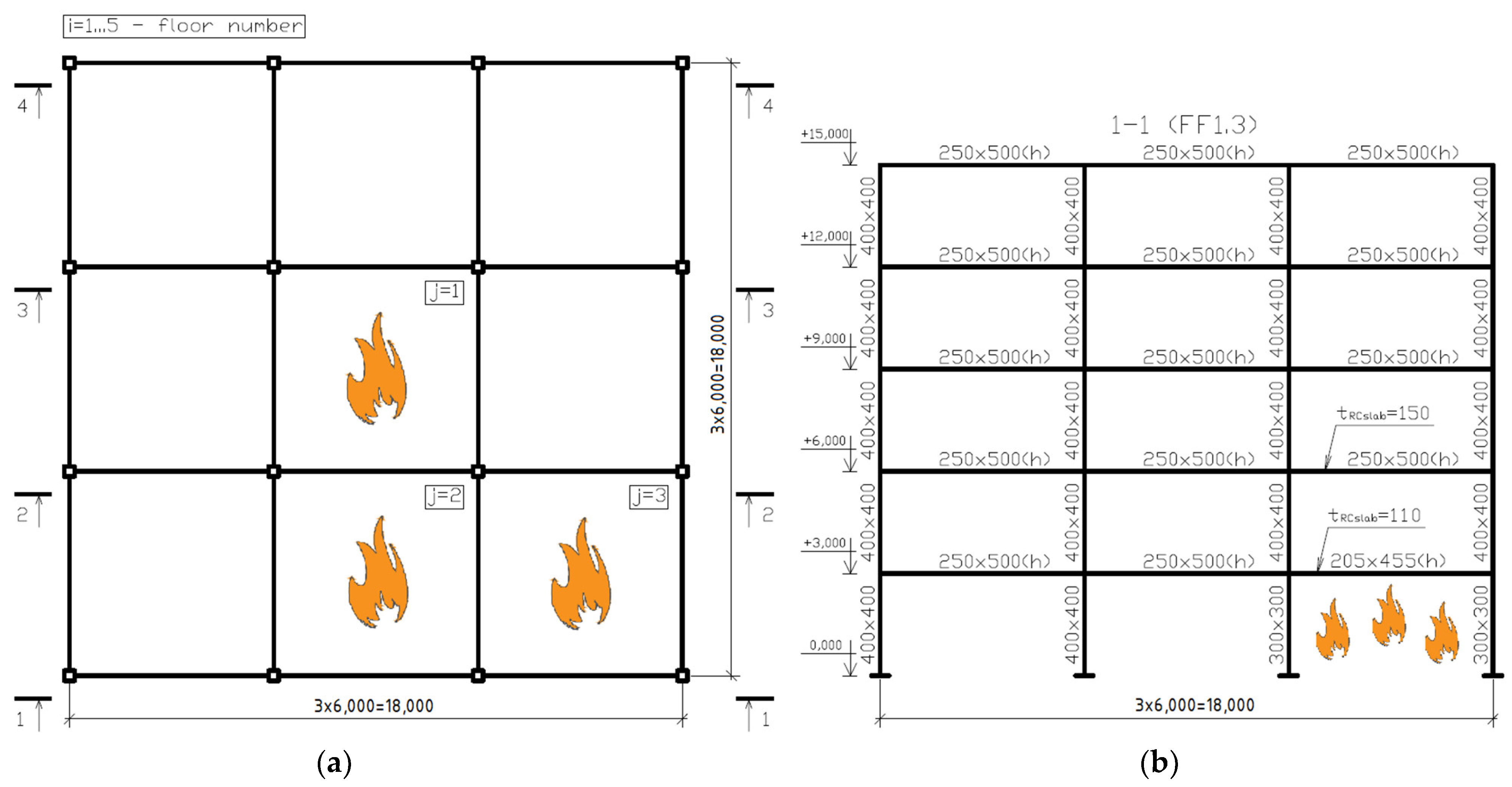
Dependency of building’s seismic response on the points of fire outbreak is exemplified by the spatial three-span five-storied frame (Figure 1). The frame on the plane is formed by the columns’ unit 6 × 6 m. The floor height is 3 m.
Design scheme of a building is done by means of the software complex ANSYS and represents multi-storied frame. Columns and beams and modelled with the help of spatial finite elements, whereas floor slabs are simulated by the plates. Members’ joints are rigid.
The first-floor columns were stiffly embedded in the foundation. The central planes were displaced downward in such a way that the upper pane of a floor slab coincided with the upper pane of the beam.
The reinforced concrete frame had a framed structural scheme—accommodation of the horizontal and vertical loading was performed by means of frames with rigid column–beam joints. The dimensions of the column’s cross-section were and the beams were .
An in situ floor slab with a width of was placed along the beams.
The structural material was concrete of grade B25. The initial elasticity modulus of concrete was 30,000 MPa. Reduction of the members’ stiffness due to crack formation was accounted for by introduction of a correcting coefficient of 0.5 to the concrete elasticity modulus.
The structural diagram is related to the middle class of plasticity (DCM under EN 1998-1). The building’s stiffness was regular height as well as in the building plan. To simplify the model, random eccentricity was not factored in.
2.2. Vertical Loading
While carrying out seismic analysis of a building, vertical permanent and temporary loads were accounted for. Permanent loads represent the dead weight of structural members of a building, the weight of floors and coverings, partitions, and the weight of wall envelopes.
The dead weight of structures is accounted for automatically in the software complex Ansys, and the specific mass of reinforced concrete is assumed equal to .
Live loads are set as evenly distributed along the floor area. The total value of evenly distributed loading was assumed equal to .
Permanent loading is accounted for by means of increases in the specific mass of the floor slab.
2.3. Seismic Impact
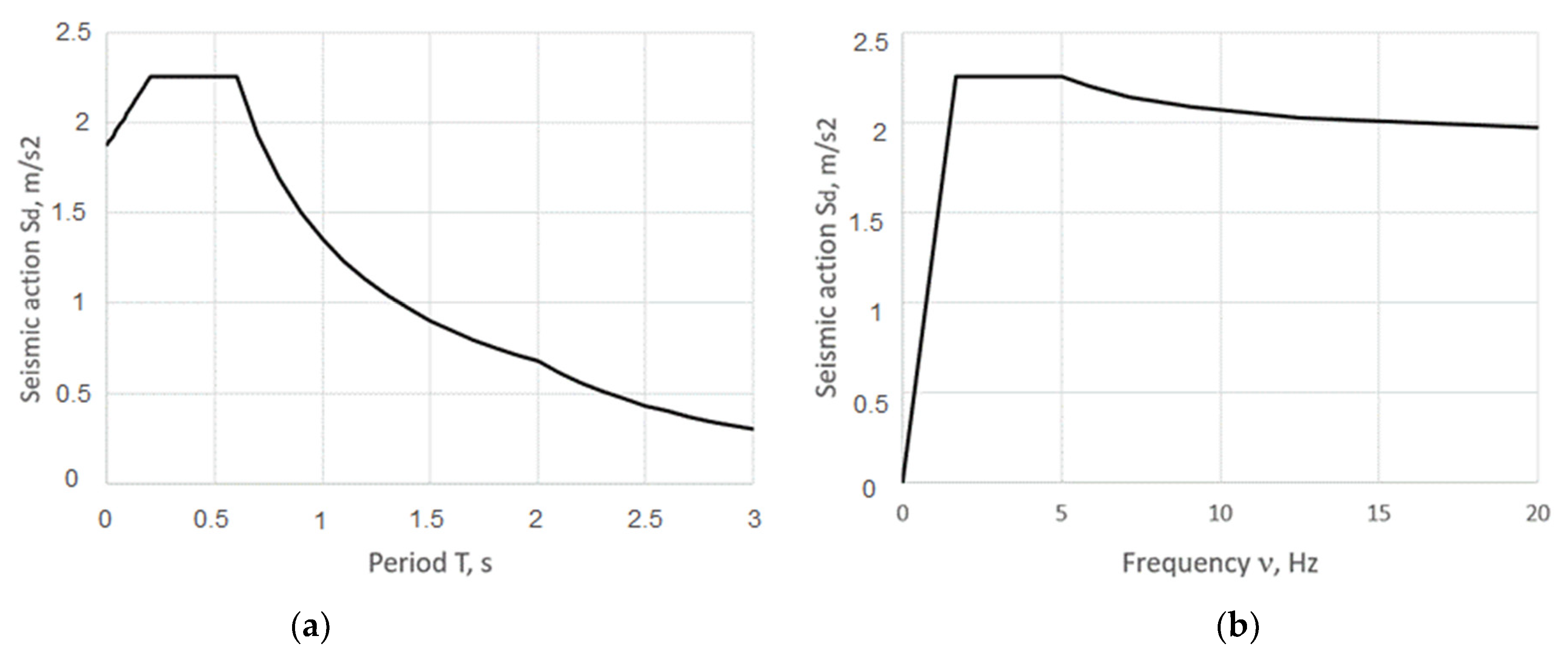
For the seismic action, a computed spectrum of response was assumed for the horizontal component of the seismic action under EN 1998-1 (Figure 2). The type of spectrum was 1.2, and the type of soil was C. Calculated soil acceleration accounts for .
The periods describing the shape of elastic spectrum are equal to , , , and the coefficient of soil conditions accounts for . The spectrum of response is determined at a damp ratio of 5%.
The capacity of the frame to dissipate the energy of seismic oscillations owing to non-elastic performance of its members is factored in by means of introducing the behavior coefficient q into the equation of the elastic spectrum. In the Russian codes of structural design in seismic-prone areas, SP 14.13330.2018, the coefficient of allowance for admissible damages K1 is introduced instead of the behavior coefficient.
The numerical value of the behavior coefficient q depends on the type of building’s structural system, plasticity class and regularities of stiffness along the building’s height and in the plan. At the event of the fire that occurred in one of the sections, initially, the regular building acquires nonregularity due to the drop in stiffness of the members damaged by the fire.
Therefore, each scheme of the fire action would have its own behavior coefficient q, whereas its value should be corrected by means of non-linear methods requiring some supplementary research.
In the present work, the behavior coefficient q is set to the same value for all the schemes of fire action and is assumed equal to 3.12.
Only horizontal component of seismic impact was accounted for. Horizontal loading is directed toward two panes of a building’s plan, in the given case—along the axis OX (Figure 1).
2.4. Fire Action
Various locations of fire outbreak points were analyzed for building’s height alone and in the plan. For each floor, there were considered three variants of location of fire outbreak points: in the middle, edge and corner units (Figure 1). Apart from this, there was studied the variant when there is no fire action. Altogether, there were 16 variants of analysis for the researched spatial frame.
Depending on the fire outbreak location, the following frame marking is accepted FFi.j, where i–the floor number; j–equal to 1 for the fire in the middle unit, 2–in the edge unit, 3–in the corner unit. For example, FF3.2–reinforced frame damaged by fire on the third floor in the edge unit. The frame non-damaged by fire is marked as FNF
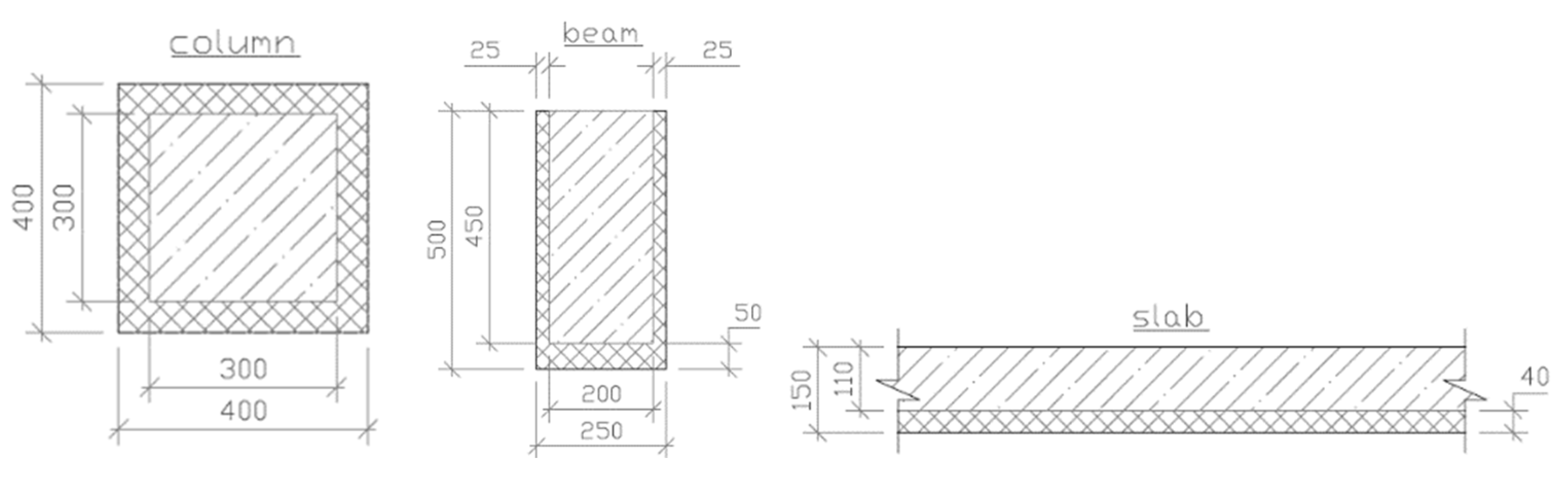
It was conventionally assumed that only 4 columns, 4 beams and upper floor slab in the unit 6 × 6 m are damaged by fire. Along with that, it is assumed that columns are damaged by fire on an even basis from four sides, beams–from three sides, and only lower pane of a floor slab is damaged. Temperature patterns in the cross-section of reinforced members correspond to the action of standard fire under ISO 834 with the duration of 120 min. Damages are accounted by reducing the size of members’ cross-section under the methodology STO 36554501-006-2006(Organization Standard) «Regulations on provision of fire resistance and fire durability of reinforced concrete structures». The following sized of cross-section were obtained for the damage members (Figure 3), where the shading shows fire-damaged parts of the elements:
- -
- column
- -
- beam
- -
- floor slabwhere (), ()—the initial width (height) of the column and beam cross-section, respectively;
, —the depth of the concrete thermal curing up to critical temperature in a column and beam, respectively.
The members in adjacent units are considered non-damaged.
2.5. Storied Masses
Storied masses are determined in compliance with EN 1998-1.
The weight of structures for floors, partitions and wall envelopes is accounted for by increasing the specific weight of the floor slabs. Thus, the specific weight of a floor slab equals:
where —permanent load evenly distributed along the floor area, ; —floor slab thickness.
As described above, the sizes of the cross-sections of the bearing structures are reduced as a function of depth of concrete thermal curing up to the critical temperature. Along with that, the weight of the structural members does not change, as damage concrete is still retained by the cross-section.
In order to factor in the latter, specific weights of the members are increased:
- -
- column
- -
- beam
- -
- floor slab
3. Results
3.1. Modal Analysis
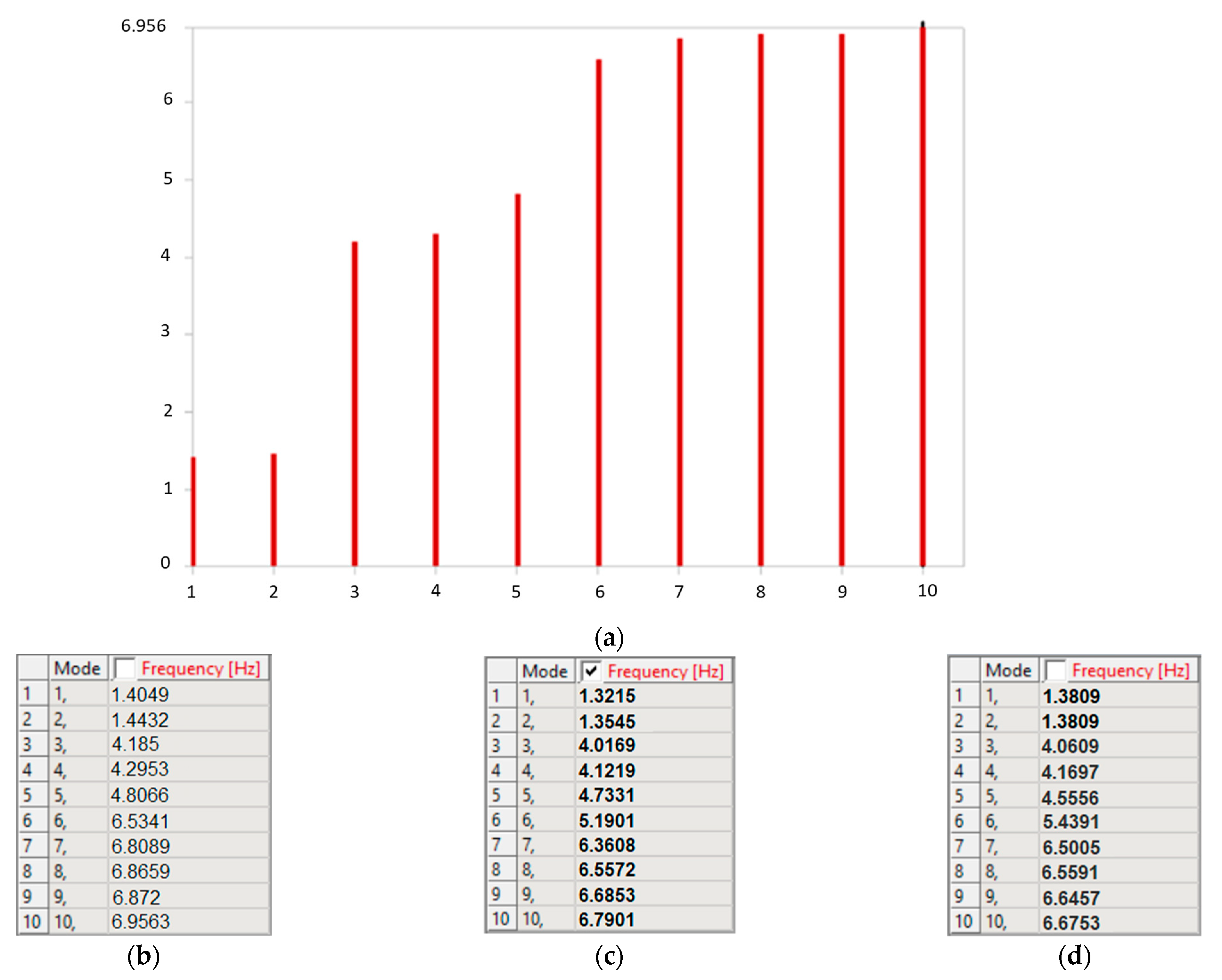
There was carried out modal analysis determining 10 oscillation modes for each frame. The results for the frames FNF, FF1.3 and FF5.1 are given in the Figure 4.
As seen from the figure, modal frequencies for the frames damaged by fire are lower than for non-damaged ones. Frequency is reduced more intensely in the event of fire at the first floor of a building and is gradually reduced in the event of fire at the upper floors. For example, if the point of fire outbreak is located at the fifth floor, the frequency of proper oscillations is approaching the frequency of a building, non-affected by fire action.
When the fire front is approaching the corner unit, i.e., the asymmetry of the bearing structures’ stiffnesses in the plane is increasing, the drop on oscillations frequency is also observed. The lowest values of proper frequencies were obtained for the frame with damaged middle units, whereas the highest were for the corner units.
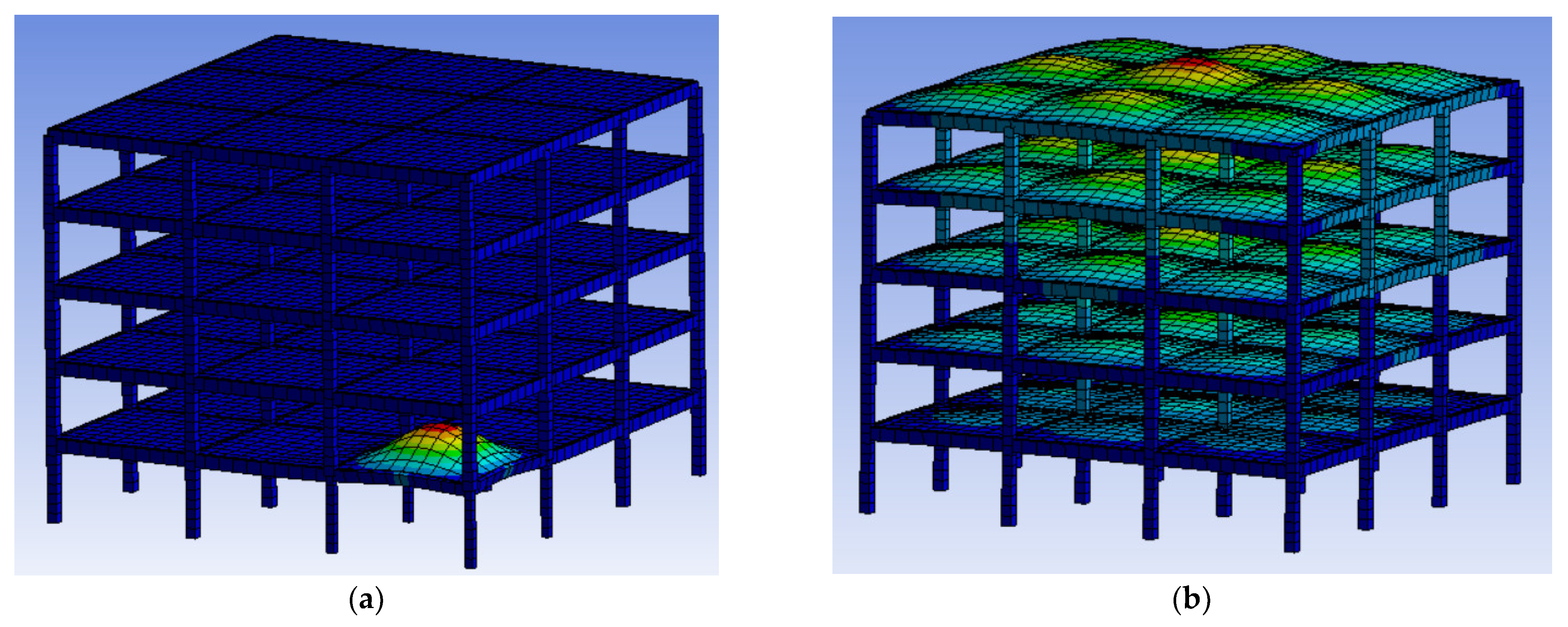
The greatest change in proper frequencies occurred in the case of the sixth axial mode. In addition, the form of this type of vibration has changed significantly (Figure 5). Displacements are concentrated in the overlapping zone for the unit damaged by fire. This could lead to the system’s responses at the impact of the vertical component of the seismic load.
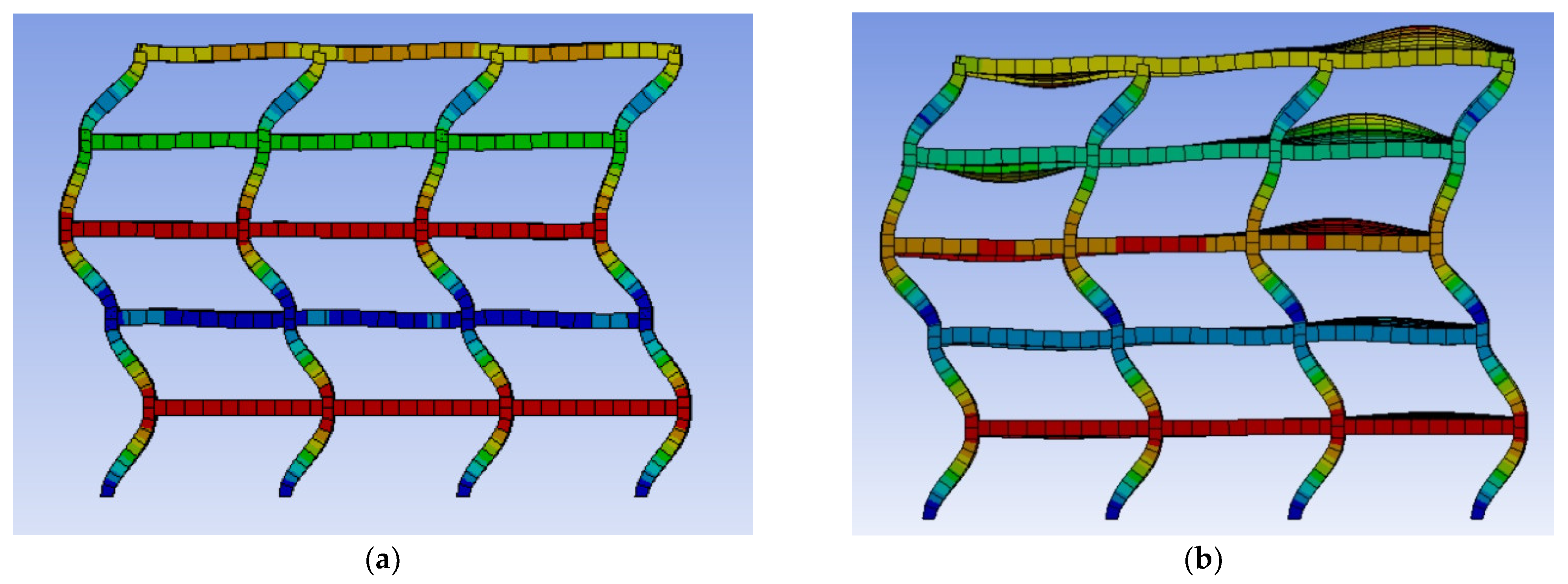
Bending (Figure 6) and torsional oscillation modes also do not change their type after the event of a fire. This could be explained by the presence of a more responsive floor affected by fire action. The concentration of displacement in the responsive floor zone is observed, which is more prominent at higher oscillation modes.
Table 1 gives the outline of the modal analysis results for five reinforced concrete frames at various positions of the fire action. The frames of types FNF, FF1.1, FF1.2, FF1.3 and FF3.3 were taken for comparison purposes. The results are enclosed for six modes for each frame. As seen from the table, the first five oscillation modes are sufficient to comply with the regulations EN 1998-1 (the summary of effective modal masses is not less than 90% of the total modal mass).
Effective modal mass of the first oscillation mode comprises mainly translational motions along the axis OX, and for the second mode, displacements along the axis OZ when the fifth one is in torsional mode.
It is worth mentioning that the second translational mode greatly affects torsion about a vertical axis OY. The greater the distance from fire outbreak point to floor slab’s center of gravity, the higher the influence.
As seen from the analysis results, the share of effective modal masses, predominant for this direction of oscillation mode, could whether increase (frames FF1.1, FF1.2, FF1.3), or be lower of the initial value, contrariwise (frame FF3.3). The same effect is observed for the sum of effective modal masses.
3.2. Displacements
Horizontal displacements obtained from the seismic analysis on the basis of the computed spectrum, according to the EN 1998-1, should be multiplied by the behavior coefficient. The ratio of the largest horizontal displacement to the total building height accounts for .
In Table 2, the comparison of the absolute floor displacements is outlined for all the frame types. Maximum displacements at the floor slab level arise for the frame non-affected by fire, whereas for damaged frames, the displacements are slightly lower.
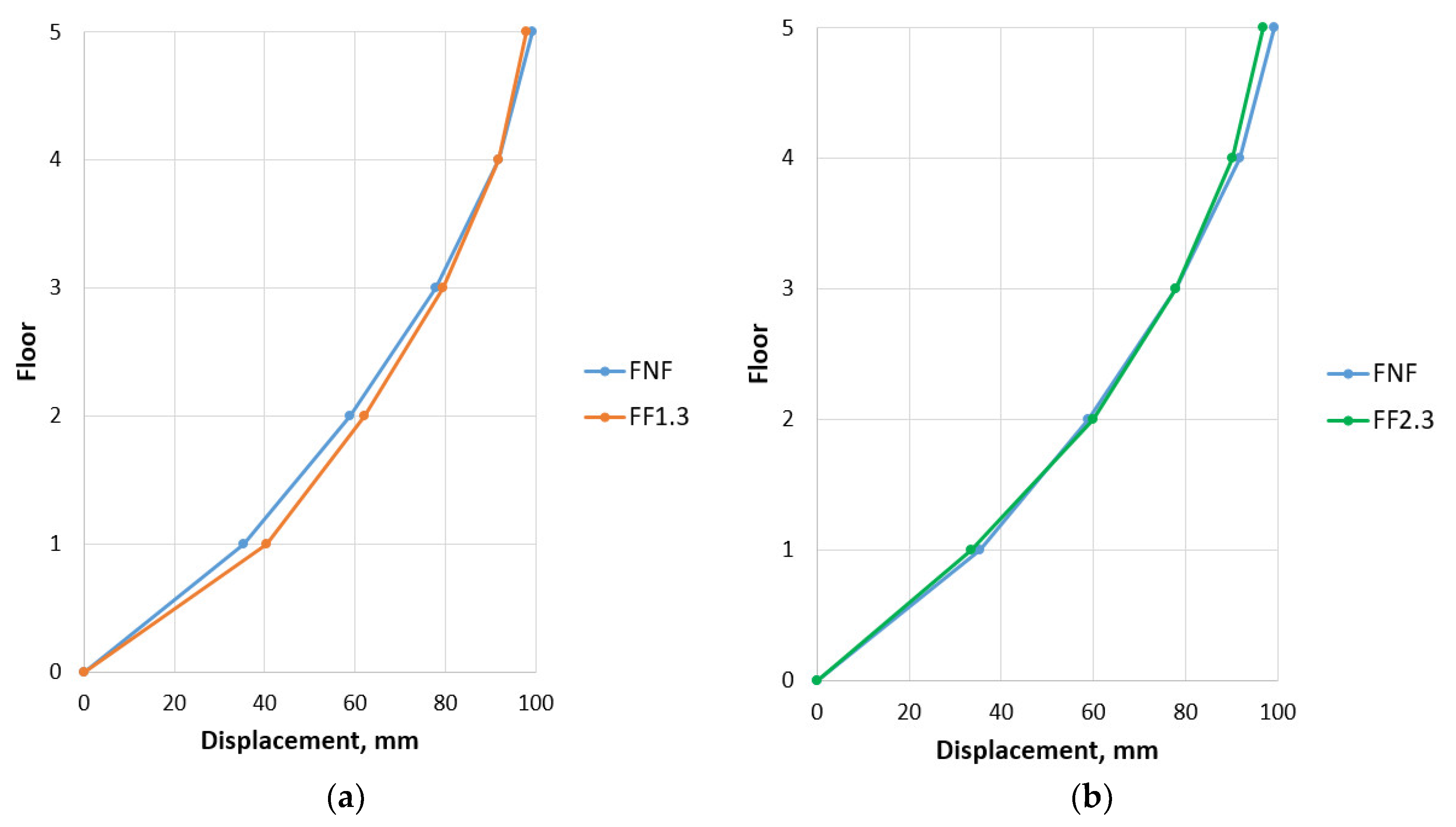
However, the displacements increase sharply at the level of the floor where the structures are weakened by fire action (Figure 7). This could be explained by lesser stiffness of this floor. Along with that, displacements of the upper floors tend to the displacements obtained for the non-damaged frames.
In Table 3, when fire front is moving toward the corner span, frame displacements appear in the direction perpendicular to the seismic impact (along the axis OY), due to increases in the asymmetry of the bearing structures’ stiffnesses. Unessential torsion of a building in the plan is observed. When the fire breaks out in the edge span, this effect is practically absent.
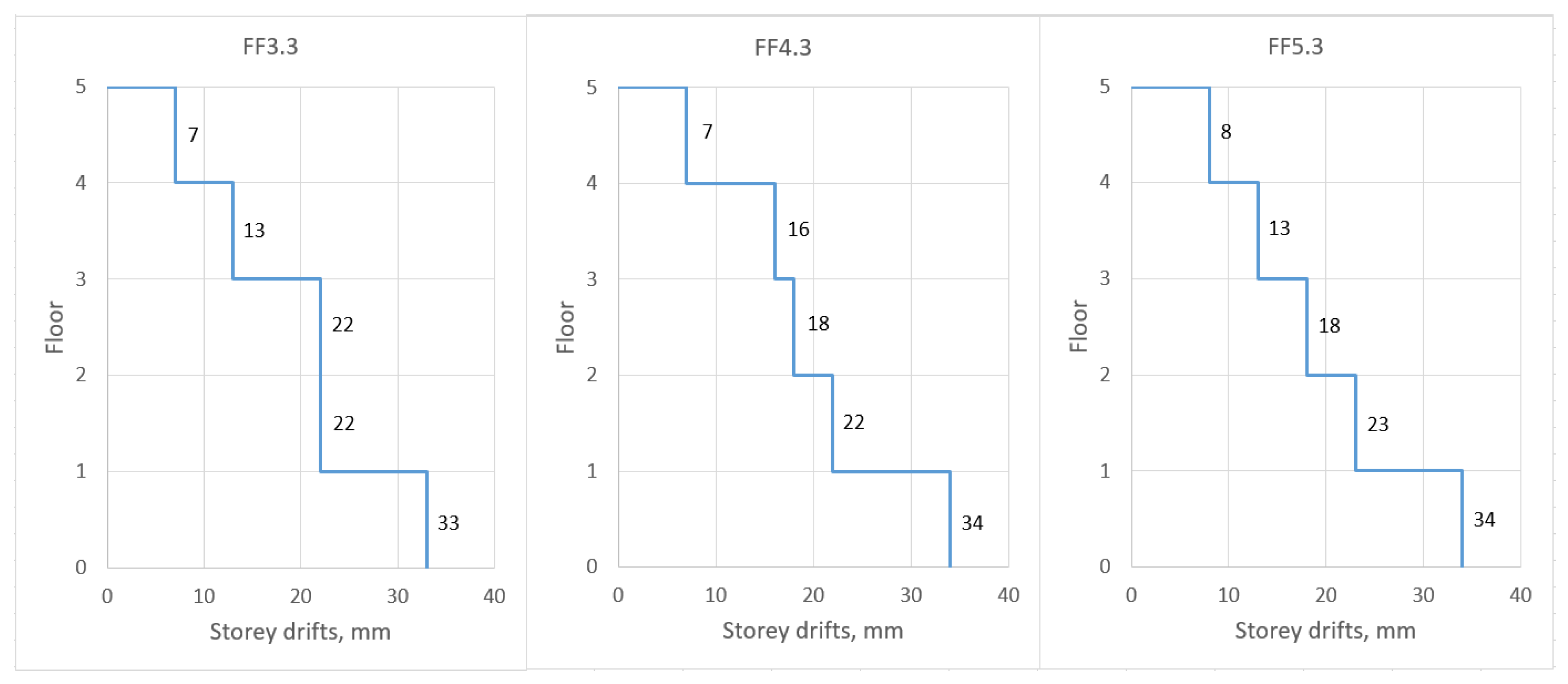
In compliance with EN 1998-1, in order to ensure the integrity of non-structural members, it is necessary to check the conditions on inter-storey drifts limitation. Inter-storey drift is equal to the difference between the absolute displacements of adjoining storeys. Construction codes put the limit on inter-storey drift under the following condition
where –inter-storey drift; –the coefficient of reduction depending on the class of the site importance (the recommended values 0.4 or 0.5); –storey height; –numerical coefficient depending on the type of non-structural members.
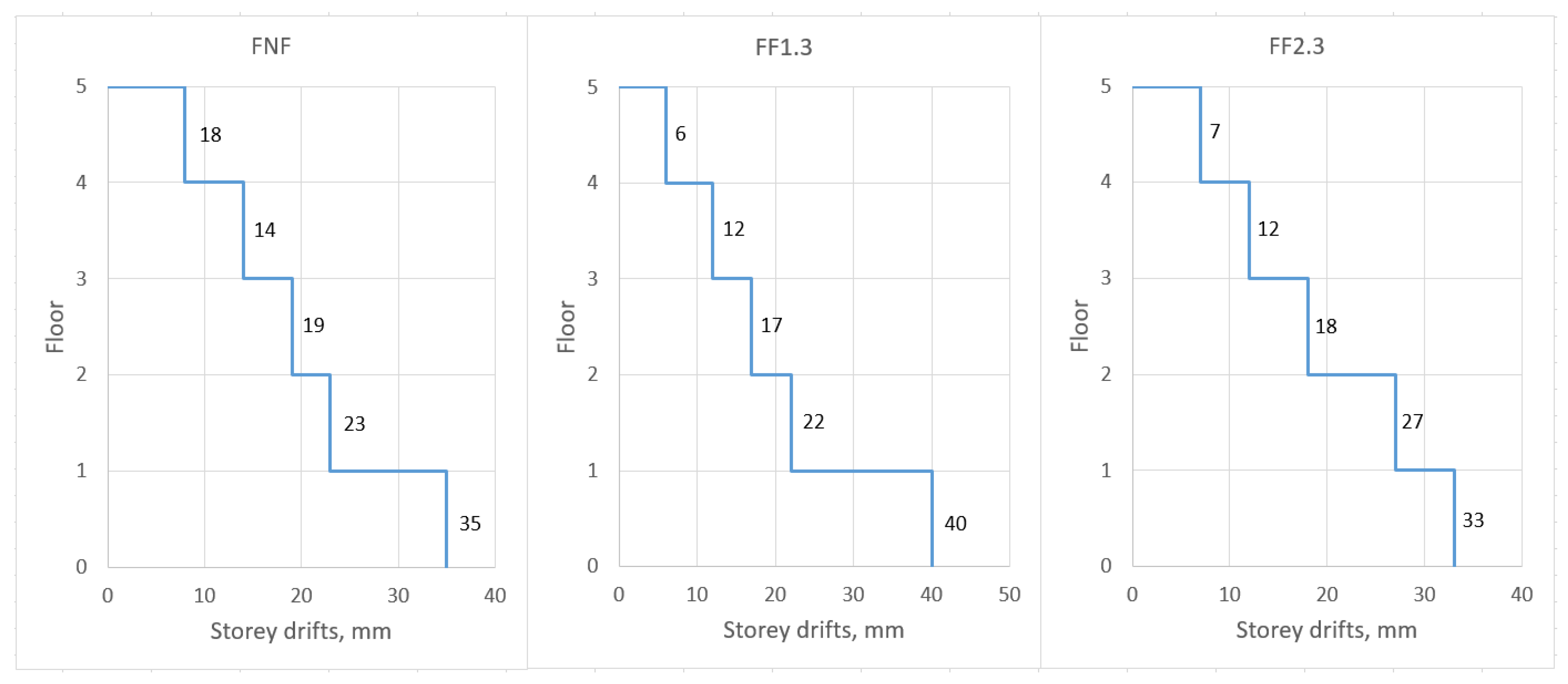
As seen from the Figure 8 at the level of the damaged floor (for frames FF1-5.3), inter-storey drifts are growing. Thus, reinforced frame designed on the base of condition of damage constraints might fail satisfying this condition after the event of fire. For instance, when comparing relative shear between the first and the second storey for the frames FNF and FF1.3, let us point out that if in the Formula (9) the values and , we obtain
- -
- for frame FNF
- -
- for frame FF1.3
As seen, for frame FF1.3, this condition is not met.
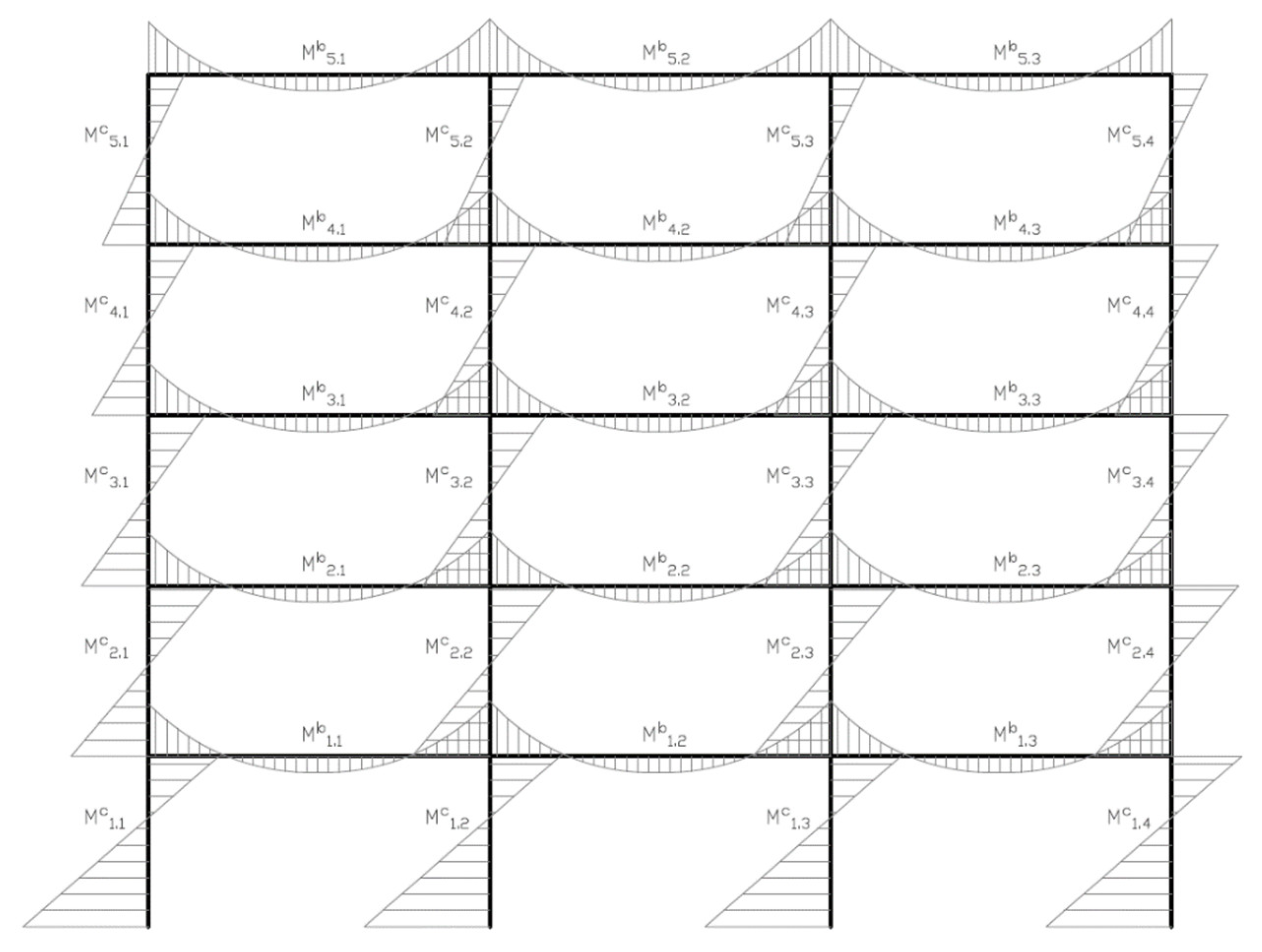
3.3. Stress
The values of maximum bending moments arising in the cross sections of columns and beams as a function of combination of static and seismic impacts are given in the Table 4 and Table 5, whereas the diagrams of bending moments are presented in the Figure 9. The maximum bending moments in the elements occur in the sections adjacent directly to the nodes of their conjugation. Decrement of column stiffness after the fire action leads to redistribution of the stress between the columns on the given and the adjoining floors. This redistribution is happening more intensely on the floors nearest to fire front. Bending moments in the damaged columns are lowered from seismic impact, whereas in the adjacent columns, on the contrary, are increased, more moments arising in non-damaged frames are found (the frame FNF). This process is exemplified by the frames FNF and FF1.1. Contrariwise, bending moments in the columns of upper floors are slightly reduced.
In the case of fire causing asymmetry of bearing structures’ stiffnesses in the plan, redistribution of stress occurs even more intensely. As follows from the Table 4, columns of the first floor, non-damaged by fire, for the frame FF1.3 are found overloaded by more than 20% as opposed to the columns of the frame FNF. When the fire front is removed within the boundaries of the first floor, the share of the load redistributed on the columns is lowered.
Apart from this, alignment of bending moments is observed for edge and middle columns of upper floors. Alignment of stress after the fire is also observed for beams.
Redistribution of stress on the adjoining columns is observed at fire outbreak at upper floors, for example, for the frame FF3.3. Non-damaged columns on the third-floor level are found to be overloaded by 18%. The strain in the columns of upper and lower floors are reduced.
4. Discussion
The considered criteria of evaluation of reinforced concretes structures seismic resistance are found sensitive to fire action preceding seismic impact at a greater or lesser extent.
From the results of modal analysis, it was stated that for all the frames damaged by fire there takes place the reduction of frequencies of proper oscillations or the in-crease in the periods value. The maximum frequency reduction was obtained when the fire broke out at the first floor in the corner span (frame FF1.3). However, for the given structural diagram of a building, the difference does not exceed 7% as opposed to a non-damaged frame.
In the certain cases, lowering of proper oscillations could increase structure’s sensitivity to the specified response spectrum. Actually, both reduction of frequency and the increase of the period of proper oscillations enhance the value of seismic impact that is nearing the maximum value on the horizontal section of spectrum (Figure 2).
It was stated that apart from frequencies the oscillation modes also change. For example, the presence of more responsive floor slab exposed to fire action led to localization of oscillations around this slab for the 5th oscillation mode. The presence of such weakened members could require the analysis of higher oscillation modes.
While analyzing building’s displacement under the impact of seismic loading, it could be noted that the amplitude of the drift of the building’s top damage by fire does not increase in all the cases but contrariwise insignificantly decreases. Thus, the total deformation of a building does not increase.
However, displacements within the boundaries of floors damaged by fire are increased locally. These displacements are characterized by inter-storey drifts. As shown above, this could lead to the fact thatsystem would fail meeting the requirements restraining the damages under EN 1998-1 that could affect integrity, for example, wall and window fillings.
Apart from this, the growth of inter-storey drifts might lead to the increase of the effects of the 2nd order that must be controlled additionally.
Frames’ torsion manifested at the fire outbreak location in the corner span is found insignificant. However, for the systems more sensitive to torsion oscillations, it could be possible the appearance of additional bending moments in the system’s members with asymmetry of bearing structures stiffnesses in the plan caused by fire.
As the results of numerical modelling have shown, fire outbreak in one of the building’s units could lead to redistribution of the strains between frame members and the increase in the bending moment in non-damaged members up to 20%.
Extrapolating the results of seismic calculation by linear-spectral method in the elastic statement on the real non-linear behavior of reinforced concrete frame exposed to low-cycle impacts, the following mechanism of its failure could be described.
In the results of fire impact in one of a building’s sections, there will occur the weakening of structures located in the point of fire outbreak. In the first instance, such a weakening is related to exacerbation of strength, stiffness and damping properties of members.
It is obvious that the seismic response of a building in whole will change: almost immediately the members damaged by fire will transfer into the plastic phase and will be partially excluded from the performance whereas nondamage members will be found overloaded due to redistribution of strains from the weakened members.
To retain the structure’s integrity, should be provided the following:
- (1)
- The reserve of plastic performance of the members damaged by fire on the impact of seismic loads and avoidance of brittle failure;
- (2)
- The reserve of bearing capacity of non-damaged members for withstanding of redistributed loads;
- (3)
- When the members damaged by fire are fully excluded from the performance, it is required to ensure building’s integrity against progressive failure during the earthquake.
Presently, seismic analysis of reinforced concrete structures after the fire in non-linear statement requires further investigation. This is related, first of all, to the great number of factors variable depending on the issue, for instance, the level of static loading, the reinforcement pattern, various conditions of fire propagation, etc.
Apart from this, in engineering practice it should be rational to conduct analysis by linear-spectral method of calculation, which is considered the framework of design codes in seismic-prone areas of many countries (EN 1998-1, SP 14.13330.2018, etc.).
As mentioned above, the main complicatedness lies in allowance for non-linear performance. This is done by introduction of behavior coefficient q (EN 1998-1) or the coefficient of admissible damages K1 (SP 14.13330.2018). Many researches have shown that the data within the norms for the coefficients q and K1 values do not reflect the specifics of non-linear performance of bearing capacity in the majority of cases [23]. It is clear that additional correction of acceptable coefficient by non-linear methods is required when a structure withstands seismic impact.
The following main steps could be identified to overcome the above-mentioned issues in the further studies:
- (1)
- Development of theoretic methodology of analysis of reinforced concrete columns and beams on seismic loading in the cross-section with plastic centroids after the fire with due account to the real picture of crack formation [25]. Obtaining of the diagram “moment-curvature”.
- (2)
- Obtaining of calculation verification in the analytical form and constructive recommendations in order to prevent undesirable mechanisms: concrete brittle failure, the loss of stability in compressed reinforcement, shear failure, etc.).
- (3)
- Development of finite-element models for seismic analysis of full-sized reinforced concrete buildings by non-linear dynamic method with account to damages from local fire. Along with that, it is planned to allow for non-linearity by means of theoretical diagram “moment-curvature” [26].
- (4)
- Obtaining the formulas for determining the coefficients of admissible damages q and K1 for implementing seismic calculations of reinforced concrete buildings after the fire by linear-spectral method.
Special attention should be paid to the fact that the scenario of fire propagation in the present study was assumed conventionally. Fire breaks out in a separate random part of a building (section), while fire propagation depends on a number of factors and is described by complex regularities (for example, Eurocode EN 1991-1-2:2002). Therefore, it is necessary to conduct further research with due account to real conditions of fire propagation and their impact on seismic response of a building.
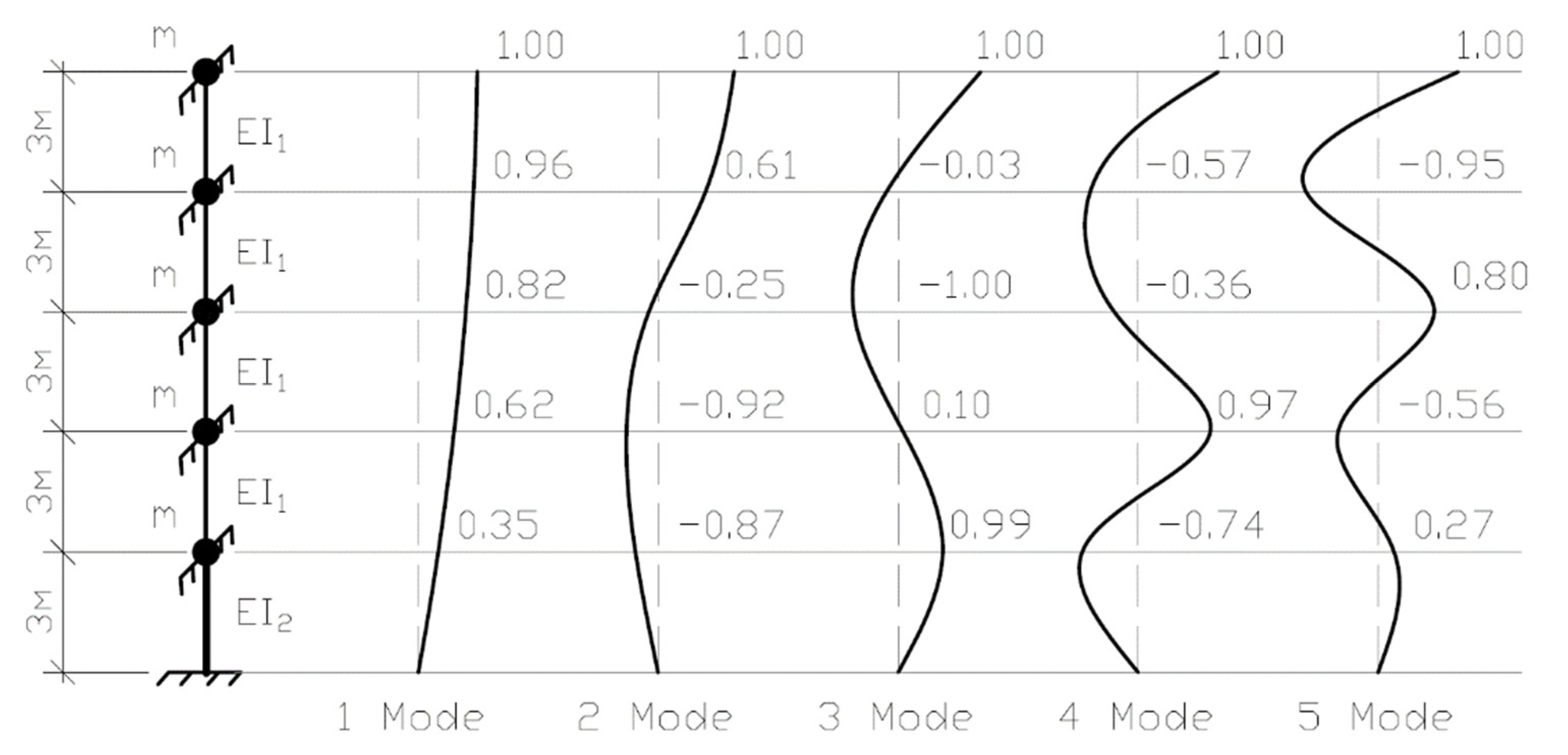
In conclusion, we distribute for the reinforced concrete frame FF1.1 under oscillations mode in analytical form and compare with the results of numerical analysis.
As a computational model, there was adopted the cantilevered system with five degrees of freedom (Figure 10). It can be assumed that bending stiffness of a floor slab structure is much higher than the columns’ stiffness. This will be accounted by introduction of joint embeddings that do not constrain translational degrees of freedom.
Joint masses m are equal at all floors and include the masses of floor slabs, beams, floors, partitions, wall envelopes and columns on the level of one floor. Mass m is equal to 456 tons.
Stiffnesses of columns on the level of one floor account for:
- -
- for floors
- -
- for the floor (damaged by fire in the central unit)
The analysis is made by the displacement method. Thus, the equation of system movement can be composed as follows:
where —the reaction in i, which is an additional bond of the main system at a singular displacement of , additional bond;
—displacement of k-joint.
The solution of the equations system could be found in the form of, where —the amplitude coefficient under the -form, —oscillations frequency. Taking into account that and introducing the denotation , we have
It could be noted that the intercept term in the brackets of the fifth equation in the system (15) has the value of 1.83 but not 2 that proves the lower total stiffness of the 1st floor columns.
In order to calculate the proper value λ, the condition is applied stating that the determinant consisted of the coefficient at ai is equal zero. While opening the determinant and solving the equation of the 5th order, we have
The values of proper frequencies can be estimated as follows:
and periods
In order to calculate the proper vectors, the well-known methodology from dynamic of structures course has been applied. Dissection into five oscillation modes is given in the Figure 10. It can be noted that analytical cantilevered model with joint embedding’s can be applied during preliminary seismic calculations of the systems after the event of fire.
While the fire breaks out in the edge and corner spans causing asymmetry of stiffnesses in the plan, it is necessary to account for torsional degrees of freedom.
5. Conclusions
The authors carried out the study of sensitivity criteria for evaluation of seismic resistance of reinforced concrete structures to various location of fire action as exemplified by three-span fire-storied reinforced concrete spatial frame.
Frequencies of proper oscillations of reinforced concrete frames after the fire in all cases were lower than for the non-damaged frame that leads to increment of seismic impact on a building. Apart from this, the type of several modes has changed when oscillations were localized around the structures damaged by fire. This could require analysis of higher mods in certain cases.
Fire action did not downgrade the total stiffness of frames in horizontal direction. However, inter-storey drifts are considerably increased within the boundaries of storeys damaged by fire. The most prominent increase in the relative drift is observed when fire breaks out at the 1st floor in the corner span of the frame. This could result in the damage of non-structural members and augmentation of the 2nd order effects.
Stress in structural members of frame exposed to fire action are redistributed un-der seismic loading. Stress in damaged members is reduced whereby the adjacent members are experiencing extra load, contrariwise. This could lead their premature transition into the plastic phase or failure.
The authors outlined the conceptual description of failure mechanism for rein-forced concrete frame factoring in its non-linear behavior. The necessity of providing the reserves of bearing capacity and plasticity of members is grounded. Further trends of development of the methodology for seismic analysis of building with reinforced concrete frame after fire out outlined.
There was obtained rather high reproducibility of numerical calculation with analytical cantilevered model with joint embeddings that could be applied at preliminary calculations.
Author Contributions
Conceptualization, A.T. and T.M.; methodology, A.T.; software, A.T. and T.M.; validation, A.T. and T.M.; formal analysis, A.T. and T.M.; investigation, A.T. and T.M.; resources, A.T. and T.M.; data curation, A.T. and T.M.; writing—original draft preparation, A.T. and T.M.; writing—review and editing, A.T.; visualization, A.T. and T.M.; supervision, A.T.; project administration, A.T. and T.M.; funding acquisition, A.T. and T.M. All authors have read and agreed to the published version of the manuscript.
Funding
This research received no external funding.
Institutional Review Board Statement
Not applicable.
Informed Consent Statement
Not applicable.
Data Availability Statement
The data presented in this study are available on request from the corresponding author.
Conflicts of Interest
The authors declare no conflict of interest.
References
- Taylor, J. Post Earthquake Fire in Tall Buildings and the New Zealand Building Code. Master’s Thesis, University of Canterbury, Christchurch, New Zealand, 2003. [Google Scholar]
- Chen, W.F.; Scawthorn, C.; Goulias, K. Earthquake Engineering Handbook; CRC Press: Boca Raton, FL, USA, 2002; p. 1512. [Google Scholar] [CrossRef]
- Della Corte, G.; Landolfo, R.; Mazzolani, F.M. Post-earthquake fire resistance of moment resisting steel frames. Fire Saf. J. 2003, 38, 593–612. [Google Scholar] [CrossRef]
- Cousins, W.; Thomas, G.; Llyodd, D.; Heron, D.; Mazzoni, S. Estimating Risks from Fire Following Earthquake; Research Report Number 27; New Zealand Fire Service Commission: Wellington, New Zealand, 2002; Available online: http://www.fire.org.nz/research/reports/reports/Report_27.htm (accessed on 30 August 2022).
- Scawthorn, C.; Yamada, Y.; Iemura, H. A model for urban post-earthquake fire hazard. Disasters 1981, 5, 125–132. [Google Scholar] [CrossRef] [PubMed]
- Sekizawa, A. Post-Earthquake Fires and Performance of Fire-Fighting Activity in the Early Stage in the 1995 Great Hanshin Earthquake; National Research Institute of Fire and Disaster, Ministry of Home Affairs: Tokyo, Japan, 1997. [Google Scholar]
- Chen, Y.-H. Experimental research on post-fire behavior of reinforced concrete columns. Fire Saf. J. 2009, 44, 741–748. [Google Scholar] [CrossRef]
- Jin, L.; Li, X.; Zhang, R.; Du, X. Meso-scale modelling the post-fire seismic behavior of RC short columns. Eng. Fail. Anal. 2021, 120, 105117. [Google Scholar] [CrossRef]
- Demir, U.; Goksu, C.; Binbir, E.; Ilki, A. Impact of time after fire on post-fire seismic behavior of RC columns. Structures 2020, 26, 537–548. [Google Scholar] [CrossRef]
- Xu, Y. Post-fire seismic behaviors of concrete stub columns indifferent fire exposure cases. Zhendong Yu Chongji/J. Vib. Shock. 2020, 39, 11–19. [Google Scholar]
- Shi, B.; Wang, G.; Mao, X. Experimental research on seismic performance of steel reinforced concrete columns after exposure to fire. Jianzhu Jiegou Xuebao/J. Build. Struct. 2017, 38, 117–124. [Google Scholar]
- Mostafaei, H.; Vecchio, F.J.; Bénichou, N. Seismic Resistance of Fire-Damaged Reinforced Concrete Columns. Improving the Seismic Performance of Existing Buildings and Other Structures; American Society of Civil Engineers: San Francisco, CA, USA, 2009; pp. 1396–1407. [Google Scholar]
- Matsudo, M.; Nishida, H.; Satoh, Y.; Takamori, N. Flexural and shear tests of ultra-high-strength reinforced concrete columns with fire protection after fire heating: Part 1 study on seismic performance of ultra-high-strength reinforced concrete columns after fire heating. J. Struct. Constr. Eng. 2009, 74, 2137–2144. [Google Scholar] [CrossRef] [Green Version]
- Tamrazyan, A.G.; Avetisyan, L.A. Experimental and theoretical study of reinforced concrete elements under different characteristics of loading at high temperatures. Procedia Eng. 2016, 153, 721–725. [Google Scholar] [CrossRef] [Green Version]
- Ervine, A.; Gillie, M.; Stratford, T.J.; Pankaj, P. Thermal propagation through tensile cracks in reinforced concrete. J. Mater. Civil Eng. 2012, 24, 516–522. [Google Scholar] [CrossRef]
- Faggiano, B.; Mazzolani, F.M. Fire after earthquake robustness evaluation and design: Application to steel structures. Steel Constr. 2011, 4, 183–187. [Google Scholar] [CrossRef]
- Bhargava, P.; Sharma, U.K.; Singh, Y.; Singh, B.; Usmani, A.; Torero, J.; Gillie, M.; Pankaj, P.; May, I.; Manohar, C.S. Fire testing of an earthquake damaged RC frame. In Proceedings of the Sixth International Conference, Structures in Fire, Lancaster, PA, USA, 2–4 June 2010; DEStech Publications, Inc.: St. Lancaster, PA, USA, 2010. [Google Scholar]
- Liu, G. Post-fire cyclic behavior of reinforced concrete shear walls. J. Cent. South Univ. Technol. 2010, 17, 1103–1108. [Google Scholar] [CrossRef]
- Ni, S.; Birely, A.C. Simulation procedure for the post-fire seismic analysis of reinforced concrete structural walls. Fire Saf. J. 2018, 95, 101–112. [Google Scholar] [CrossRef]
- ACI Committee 374. Guide for Testing Reinforced Concrete Structural Elements under Slowly Applied Simulated Seismic Loads; American Concrete Institute: Farmington Hills, MI, USA, 2013. [Google Scholar]
- Li, L.Z.; Jiang, C.J.; Lu, Z.D. Experimental study on seismic performance of post-fire reinforced concrete frames. Eng. Struct. 2019, 179, 161–173. [Google Scholar] [CrossRef]
- Xiao, J.-Z.; Li, J.; Huang, Z.-F. Fire Response of High-Performance Concrete Frames and Their Post-Fire Seismic Performance. ACI Struct. J. 2008, 105, 531–540. [Google Scholar] [CrossRef]
- Tamrazyan, A.; Chernik, V. Equivalent viscous damping ratio for a RC column under seismic load after a fire. IOP Conf. Ser. Mater. Sci. Eng. 2021, 1030, 012095. [Google Scholar] [CrossRef]
- Wang, J.Y.; Yue, X.C.; Sun, Y.Z. Numerical simulation on the seismic performance of post-fire steel concrete frame joint bonded with steel. IOP Conf. Ser. Mater. Sci. Eng. 2019, 531, 012091. [Google Scholar] [CrossRef] [Green Version]
- Lu, Z.; Chen, Y.; Li, L.; Liu, X.; Wei, K. Experimental Study on Seismic Behavior of Plane and Spatial Concrete Beam-column Joints after Exposure to Fire. Tongji Daxue Xuebao/J. Tongji Univ. 2020, 48, 340–348. [Google Scholar]
- Li, X.; Xu, Z.; Bao, Y.; Cong, Z. Post-fire seismic behavior of two-bay two-story frames with high performance fiber-reinforced cementitious composite joints. Eng. Struct. 2019, 183, 150–159. [Google Scholar] [CrossRef]
- Su, X.P. Seismic response analysis on the repaired HSC structure after fire. Appl. Mech. Mater. 2014, 651, 1260–1265. [Google Scholar] [CrossRef]
- Mazza, F. Effects of near-fault vertical earthquakes on the nonlinear incremental response of R.C. base-isolated structures exposed to fire. Bull. Earthq. Eng. 2015, 14, 433–454. [Google Scholar] [CrossRef]
- ANSYS, Inc. ANSYS 15.0. User’s Guide; ANSYS, Inc. Southpointe: Canonsburg, PA, USA, 2014. [Google Scholar]
Figure 1.
Structural scheme of reinforced concrete frame. (a) Variants of points of fire outbreak location and (b) cross-sectional plan of the frame.
Figure 1.
Structural scheme of reinforced concrete frame. (a) Variants of points of fire outbreak location and (b) cross-sectional plan of the frame.

Figure 2.
Computed spectra of response: (a) in periods; (b) in frequencies.

Figure 3.
Cross-sections of structural members after the fire (columns, beams, floor slabs).

Figure 4.
(a) Histogram of proper frequencies for frame FNF. The values of the proper frequencies for the frames (b) FNF, (c) FF1.3, (d) FF5.1.
Figure 4.
(a) Histogram of proper frequencies for frame FNF. The values of the proper frequencies for the frames (b) FNF, (c) FF1.3, (d) FF5.1.

Figure 5.
Axial sixth oscillation mode: (a) for frame FNF; (b) for frame FF1.3.

Figure 6.
Bending seventh oscillation mode: (a) for frame FNF; (b) for frame FF4.1.

Figure 7.
Comparison of storey drifts: (a) for FNF and FF1.3; (b) for FNF and FF2.3.

Figure 8.
Comparison of inter-storey drifts for the frames FNF, FF1.3, FF2.3, FF3.3, FF4.3 and FF5.3.
Figure 8.
Comparison of inter-storey drifts for the frames FNF, FF1.3, FF2.3, FF3.3, FF4.3 and FF5.3.


Figure 9.
Diagrams of bending moments for the transverse frame (sections 1-1 … 4-4 I in Figure 1).
Figure 9.
Diagrams of bending moments for the transverse frame (sections 1-1 … 4-4 I in Figure 1).

Figure 10.
Cantilevered model of reinforced concrete frame FF1.1 and corresponding oscillation modes.
Figure 10.
Cantilevered model of reinforced concrete frame FF1.1 and corresponding oscillation modes.


Table 1.
Modal analysis results.
| Frame Type | Modes | Period T, s | Frequency ϑ, Hz | Effective Modal Masses, % | ||
|---|---|---|---|---|---|---|
| FNF | 1 | 0.72 | 1.38 | 90.5 | 0.0 | 5.5 |
| 2 | 0.70 | 1.42 | 0.0 | 90.8 | 49.6 | |
| 3 | 0.24 | 4.14 | 7.2 | 0.0 | 0.4 | |
| 4 | 0.24 | 4.25 | 0.0 | 7.0 | 3.8 | |
| 5 | 0.21 | 4.79 | 0.0 | 0.0 | 35.8 | |
| 6 | 0.15 | 6.53 | 0.0 | 0.0 | 0.0 | |
| ∑ | 97.7 | 97.8 | 95.1 | |||
| FF1.1 | 1 | 0.76 | 1.32 | 92.1 | 0.0 | 5.6 |
| 2 | 0.74 | 1.36 | 0.0 | 92.5 | 50.5 | |
| 3 | 0.25 | 4.02 | 6.2 | 0.0 | 0.4 | |
| 4 | 0.24 | 4.13 | 0.0 | 5.9 | 3.2 | |
| 5 | 0.21 | 4.75 | 0.0 | 0.0 | 36.7 | |
| 6 | 0.18 | 5.61 | 0.0 | 0.0 | 0.0 | |
| ∑ | 98.3 | 98.4 | 96.4 | |||
| FF1.2 | 1 | 0.76 | 1.32 | 92.1 | 0.0 | 5.3 |
| 2 | 0.74 | 1.36 | 0.0 | 92.5 | 50.5 | |
| 3 | 0.25 | 4.02 | 6.1 | 0.0 | 0 | |
| 4 | 0.24 | 4.13 | 0.0 | 5.9 | 3.2 | |
| 5 | 0.21 | 4.74 | 0.0 | 0.0 | 37.2 | |
| 6 | 0.19 | 5.40 | 0.0 | 0.0 | 0.0 | |
| ∑ | 98.2 | 98.4 | 96.2 | |||
| FF1.3 | 1 | 0.76 | 1.32 | 91.6 | 0.5 | 3.1 |
| 2 | 0.74 | 1.35 | 0.5 | 91.9 | 53.7 | |
| 3 | 0.25 | 4.02 | 6.0 | 0.0 | 0.0 | |
| 4 | 0.24 | 4.12 | 0.0 | 5.8 | 5.3 | |
| 5 | 0.21 | 4.73 | 0.0 | 0.0 | 35.0 | |
| 6 | 0.19 | 5.19 | 0.0 | 0.0 | 0.0 | |
| ∑ | 98.1 | 98.2 | 97.1 | |||
| FF3.3 | 1 | 0.74 | 1.36 | 89.5 | 0.1 | 4.2 |
| 2 | 0.72 | 1.40 | 0.1 | 89.8 | 50.5 | |
| 3 | 0.25 | 4.08 | 8.0 | 0.0 | 0.6 | |
| 4 | 0.24 | 4.17 | 0.0 | 7.9 | 3.5 | |
| 5 | 0.21 | 4.67 | 0.0 | 0.0 | 36.1 | |
| 6 | 0.19 | 5.15 | 0.0 | 0.0 | 0.0 | |
| ∑ | 97.5 | 97.8 | 94.9 | |||
Table 2.
Absolute floor displacement, mm.
| Frame Type | Floor 1 | Floor 2 | Floor 3 | Floor 4 | Floor 5 |
|---|---|---|---|---|---|
| FNF | 35 | 59 | 78 | 92 | 99 |
| FF1.1 | 40 | 62 | 79 | 92 | 98 |
| FF1.2 | 40 | 62 | 79 | 92 | 98 |
| FF1.3 | 40 | 62 | 79 | 92 | 98 |
| FF2.1 | 33 | 60 | 77 | 90 | 96 |
| FF2.2 | 33 | 60 | 78 | 90 | 97 |
| FF2.3 | 33 | 60 | 78 | 90 | 97 |
| FF3.1 | 33 | 56 | 77 | 90 | 96 |
| FF3.2 | 33 | 56 | 77 | 90 | 96 |
| FF3.3 | 33 | 56 | 77 | 90 | 97 |
| FF4.1 | 34 | 56 | 74 | 90 | 96 |
| FF4.2 | 34 | 56 | 74 | 90 | 96 |
| FF4.3 | 34 | 56 | 74 | 90 | 97 |
| FF5.1 | 34 | 57 | 75 | 88 | 96 |
| FF5.2 | 34 | 57 | 75 | 88 | 96 |
| FF5.3 | 34 | 57 | 75 | 88 | 96 |
Table 3.
Floor (storey) drifts in the direction perpendicular to the seismic impact (along the axis OY), mm.
Table 3.
Floor (storey) drifts in the direction perpendicular to the seismic impact (along the axis OY), mm.
| Frame Type | Floor 1 | Floor 2 | Floor 3 | Floor 4 | Floor 5 |
|---|---|---|---|---|---|
| FNF | 0.0 | 0.0 | 0.0 | 0.0 | 0.0 |
| FF1.3 | 4.0 | 7.0 | 8.0 | 10.0 | 10.0 |
| FF2.3 | 3.0 | 5.0 | 6.0 | 7.0 | 7.0 |
| FF3.3 | 2.0 | 3.0 | 4.0 | 5.0 | 5.0 |
| FF4.3 | 1.0 | 2.0 | 2.0 | 2.0 | 3.0 |
| FF5.3 | 0.0 | 1.0 | 1.0 | 1.0 | 1.0 |
Table 4.
Maximum bending moments in the columns, kNm.
| Maximum Bending Moment | Frame | ||||||||||
|---|---|---|---|---|---|---|---|---|---|---|---|
| FNF | FF1.1 | FF1.3 | FF3.3 | ||||||||
| 1-1 | 2-2 | 1-1 | 2-2 | 1-1 | 2-2 | 3-3 | 4-4 | 1-1 | 2-2 | ||
| Columns | Mc1.1 | 256 | 264 | 305 | 312 | 322 | 313 | 302 | 289 | 257 | 265 |
| Mc1.2 | 255 | 261 | 309 | 103 | 327 | 316 | 304 | 282 | 254 | 256 | |
| Mc1.3 | 255 | 261 | 309 | 103 | 110 | 105 | 305 | 293 | 254 | 256 | |
| Mc1.4 | 256 | 264 | 305 | 312 | 110 | 106 | 304 | 292 | 246 | 251 | |
| Mc2.1 | 199 | 215 | 192 | 209 | 175 | 183 | 187 | 190 | 192 | 210 | |
| Mc2.2 | 202 | 205 | 188 | 194 | 179 | 187 | 194 | 196 | 185 | 191 | |
| Mc2.3 | 202 | 205 | 188 | 194 | 175 | 187 | 194 | 196 | 186 | 193 | |
| Mc2.4 | 199 | 215 | 192 | 209 | 165 | 178 | 187 | 194 | 191 | 215 | |
| Mc3.1 | 167 | 182 | 160 | 177 | 142 | 148 | 152 | 162 | 203 | 213 | |
| Mc3.2 | 165 | 169 | 151 | 157 | 147 | 153 | 194 | 165 | 205 | 197 | |
| Mc3.3 | 165 | 169 | 151 | 157 | 146 | 153 | 194 | 165 | 77 | 71 | |
| Mc3.4 | 167 | 182 | 160 | 177 | 144 | 148 | 152 | 162 | 83 | 84 | |
| Mc4.1 | 122 | 139 | 117 | 135 | 103 | 106 | 108 | 107 | 116 | 133 | |
| Mc4.2 | 122 | 124 | 109 | 114 | 106 | 110 | 111 | 110 | 110 | 113 | |
| Mc4.3 | 122 | 124 | 109 | 114 | 106 | 110 | 111 | 110 | 110 | 116 | |
| Mc4.4 | 122 | 139 | 117 | 135 | 102 | 106 | 108 | 106 | 115 | 135 | |
| Mc5.1 | 79 | 114 | 73 | 119 | 53 | 55 | 56 | 55 | 70 | 103 | |
| Mc5.2 | 68 | 69 | 59 | 63 | 56 | 58 | 58 | 57 | 59 | 63 | |
| Mc5.3 | 68 | 69 | 59 | 63 | 56 | 58 | 58 | 57 | 61 | 63 | |
| Mc5.4 | 79 | 114 | 73 | 119 | 53 | 55 | 56 | 55 | 77 | 125 | |
Table 5.
Maximum bending moments in the beams, kNm.
| Maximum Bending Moment | Frame | ||||||||||
|---|---|---|---|---|---|---|---|---|---|---|---|
| FNF | FF1.1 | FF1.3 | FF3.3 | ||||||||
| 1-1 | 2-2 | 1-1 | 2-2 | 1-1 | 2-2 | 3-3 | 4-4 | 1-1 | 2-2 | ||
| Beams | Mb1.1 | 69 | 107 | 72 | 118 | 71 | 109 | 109 | 71 | 68 | 106 |
| Mb1.2 | 64 | 98 | 65 | 85 | 69 | 109 | 99 | 66 | 62 | 97 | |
| Mb1.3 | 69 | 107 | 72 | 118 | 72 | 110 | 109 | 71 | 68 | 106 | |
| Mb2.1 | 66 | 107 | 69 | 117 | 67 | 107 | 107 | 68 | 68 | 103 | |
| Mb2.2 | 58 | 90 | 50 | 85 | 64 | 100 | 93 | 60 | 60 | 94 | |
| Mb2.3 | 66 | 107 | 69 | 117 | 69 | 110 | 107 | 68 | 68 | 103 | |
| Mb3.1 | 64 | 107 | 65 | 116 | 63 | 105 | 106 | 64 | 66 | 109 | |
| Mb3.2 | 54 | 89 | 52 | 88 | 58 | 97 | 88 | 53 | 59 | 94 | |
| Mb3.3 | 64 | 107 | 65 | 116 | 66 | 110 | 106 | 64 | 69 | 110 | |
| Mb4.1 | 60 | 104 | 60 | 113 | 59 | 103 | 103 | 60 | 59 | 103 | |
| Mb4.2 | 48 | 84 | 46 | 83 | 53 | 91 | 83 | 47 | 50 | 88 | |
| Mb4.3 | 60 | 104 | 60 | 113 | 62 | 107 | 103 | 60 | 61 | 106 | |
| Mb5.1 | 50 | 90 | 51 | 98 | 50 | 89 | 89 | 50 | 50 | 89 | |
| Mb5.2 | 43 | 79 | 41 | 78 | 48 | 86 | 79 | 42 | 46 | 83 | |
| Mb5.3 | 50 | 90 | 51 | 98 | 53 | 93 | 89 | 50 | 52 | 92 | |
Publisher’s Note: MDPI stays neutral with regard to jurisdictional claims in published maps and institutional affiliations. |
© 2022 by the authors. Licensee MDPI, Basel, Switzerland. This article is an open access article distributed under the terms and conditions of the Creative Commons Attribution (CC BY) license (https://creativecommons.org/licenses/by/4.0/).
Share and Cite
MDPI and ACS Style
Tamrazyan, A.; Matseevich, T. The Criteria for Assessing the Safety of Buildings with a Reinforced Concrete Frame during an Earthquake after a Fire. Buildings 2022, 12, 1662. https://doi.org/10.3390/buildings12101662
AMA Style
Tamrazyan A, Matseevich T. The Criteria for Assessing the Safety of Buildings with a Reinforced Concrete Frame during an Earthquake after a Fire. Buildings. 2022; 12(10):1662. https://doi.org/10.3390/buildings12101662
Chicago/Turabian StyleTamrazyan, Ashot, and Tatiana Matseevich. 2022. "The Criteria for Assessing the Safety of Buildings with a Reinforced Concrete Frame during an Earthquake after a Fire" Buildings 12, no. 10: 1662. https://doi.org/10.3390/buildings12101662
Note that from the first issue of 2016, this journal uses article numbers instead of page numbers. See further details here.