Article

Resistance of an Optimized Ultra-High Performance Fiber Reinforced Concrete to Projectile Impact

by
Anna L. Mina
1,2,*,
Michael F. Petrou
1 and
Konstantinos G. Trezos
2
1
Department of Civil and Environmental Engineering, University of Cyprus, 75 Kallipoleos Avenue, Post Office Box 20537, 1678 Nicosia, Cyprus
2
Laboratory of Reinforced Concrete, School of Civil Engineering, National Technical University of Athens, 5 Iroon Polytechniou Street, 15773 Zografou, Greece
*
Author to whom correspondence should be addressed.
Buildings 2021, 11(2), 63; https://doi.org/10.3390/buildings11020063
Submission received: 9 December 2020 / Revised: 5 February 2021 / Accepted: 7 February 2021 / Published: 11 February 2021
(This article belongs to the Section Building Materials, and Repair & Renovation)

Abstract

:
The scope of this paper is to investigate the performance of ultra-high performance fiber reinforced concrete (UHPFRC) concrete slabs, under projectile impact. Mixture performance under impact loading was examined using bullets with 7.62 mm diameter and initial velocity 800 m/s. The UHPFRC, used in this study, consists of a combination of steel fibers of two lengths: 6 mm and 13 mm with the same diameter of 0.16 mm. Six composition mixtures were tested, four UHPFRC, one ultra-high performance concrete (UHPC), without steel fibers, and high strength concrete (HSC). Slabs with thicknesses of 15, 30, 50, and 70 mm were produced and subjected to real shotgun fire in the field. Penetration depth, material volume loss, and crater diameter were measured and analyzed. The test results show that the mixture with a combination of 3% 6 mm and 3% of 13 mm length of steel fibers exhibited the best resistance to projectile impact and only the slabs with 15 mm thickness had perforation. Empirical models that predict the depth of penetration were compared with the experimental results. This material can be used as an overlay to buildings or to construct small precast structures.

1. Introduction

When bullets hit a wall of a structure, apart from the fact that they can penetrate the wall, they can also cause spalling and scabbing that can injure people. In the worst-case scenario, the created widespread cracking can lead to a structural element or the whole structure to collapse (Figure 1). In 1983, Clifton and Knab [1] developed three test methods to assess the impact resistance of concrete. In recent years, terrorist attacks have been increasing and there is a need to design safer structures and strengthen the existing ones. Such a need requires the development of new types of concrete with superior characteristics. Ultra-high performance concrete (UHPC) is a special type of concrete with superior durability and mechanical properties which was initially used in high rise buildings [2]. Hanchak et al. [3] studied the perforation caused by steel projectiles of normal and high strength concrete slabs, with rebar reinforcement. The study concluded that, even though there was an increase in unconfined compressive strength by a factor of three, the ballistic perforation resistance for impact velocities 300–1100 m/s was marginally improved. UHPC gains strength but it becomes more brittle with minor improvement of its resistance to impact loading. To overcome this disadvantage, steel fibers with high tensile strength were added to control cracking and offer increased toughness [4] and hence ultra high performance fiber reinforced concrete (UHPFRC) was formed [5,6,7,8,9,10,11,12]. UHPFRC with advanced mechanical properties can be used for constructing new structures and for strengthening existing concrete structures that are subjected to impact loadings [13,14,15,16,17,18,19,20]. Few researchers have examined the impact response of cementitious composites reinforced with different fiber materials [21,22,23,24]. Almusallam et al. [21] concluded that fiber type does not influence the penetration depth while Kim et al. [22] and Feng et al. [23] results showed that the mixtures including only steel fibers exhibited smaller penetration depth.
Researchers have studied the benefits of UHPFRC compared to UHPC and normal concrete against impact loading. Dancygier and Yankelevsky [15] observed through an experimental study that steel fibers enhanced the resistance against projectile impact, increased ductility, and minimized damage areas. Another study by O’Neil et al. [17] resulted in the same findings that fibers reduced visible damage to the area surrounding the crater. Zhang et al. [16] indicated that “the incorporation of steel fibres in concrete reduced the crater diameter and crack propagation, but did not have a significant effect on penetration depth”.
Several research studies examined the impact resistance of UHPFRC with the use of drop hammer [25,26,27,28,29,30] and the use of projectile impact [13,14,15,16,17,18,19,20,31,32]. Other researchers used a split Hopkinson pressure bar [33,34,35]. Yu et al. [36], Yu and Li [37], and Konrád and Sovják [38] used pendulum impact setups to create impact loading.
In the current research, the mixture design used is based on a study by Benson and Karihaloo [9]. The mix design was modified by Nicolaides et al. [12] in order to use materials from Cyprus and to select the best constituent materials and curing procedure. Mechanical properties were measured using cubes for compressive strength and beams for three-point bending tests for tensile strength. It was the first UHPFRC mixture that was developed in Cyprus.
The impact resistance of the material of a previous study [9] was tested using UHPFRC slabs under real shots [39]. At first, two different weapons and projectile types were used, “solid round” projectiles 12.7 mm diameter and rocket-propelled grenade weapon (RPG) 7 HEAT 40 mm. Two slabs of UHPFRC with dimensions (1000 mm × 1000 mm × 50 mm) were produced, one slab was checked against solid round projectile and the other one against rocket-propelled grenade. Two additional slabs, with the same dimensions, of normal reinforced concrete were tested for a comparison with UHPFRC panel performance. All of the solid round projectiles penetrated the reinforced concrete slab while only 10 out of 15 projectiles penetrated the UHPFRC slab and crater volume was lower in the UHPFRC panel.
In the present experimental procedure, a further investigation was conducted to optimize the mechanical properties of UHPFRC in order to achieve a better resistance to the projectile impact of firearm Gewehr 3(G3), with 7.62 mm bullets [10,11,40,41]. The idea was to use the material as an overlay to structures or construct small precast structures, like guardrooms, outside embassies and governmental buildings. Thick small slabs of UHPFRC can be placed on a metal frame to protect existing or new structures. The dimensions of the slabs should be kept small to reduce their weight and make handling them easier. In the current research project, slabs with dimensions 200 mm × 200 mm and thickness of 15, 30, 50, and 70 mm were produced and tested under real gun shots in the field. The investigation included four UHPFRC mixtures, one UHPC, and HSC. Depth of penetration, crater diameter, and material volume loss were measured and the failure mechanisms were investigated. The UHPFRC mixture, optimized for impact resistance based on mechanical properties, performance against projectile impact was compared with the performance of other mixtures. Several slab thicknesses were tested in order to find the minimum thickness which prevents perforation from occurring. Empirical models that predict the depth of penetration were compared with the experimental results.
Studies for impact resistance of concrete were limited for many years, hence current structures are not designed to resist impact loading. In our days, terrorist attacks are increasing and the intention of this paper is to investigate the ballistic resistance of UHPFRC against real shots through experiments conducted in the field, which are still scarce. The idea is to use precast thin slabs as an overlay surface placed on a steel frame attached to existing walls or to construct small precast guardrooms to provide protection from terrorist attacks.

2. Experimental Testing

2.1. Mixture Design

Six mixture designs were tested, one UHPC without steel fibers, HSC, and four UHPFRC with steel fibers. A combination of two lengths of straight smooth steel fibers was used: 6 mm long with 0.16 mm diameter and 13 mm long with 0.16 mm diameter. Both short and long length fibers helped by bridging cracks different size of developed cracks. The aspect ratio for short fibers is 37.5 and for long fibers is 81.25. The use of two lengths of steel fibers was adopted from a previous study [9,12]. The mechanical properties of the selected previous mix design were further improved in order to achieve the best performance under projectile impact [40]. The basic composition of the mixture was the same with modifications in the percentages of fibers by volume, length of steel fibers, and the quantity of water. The mixture without steel fibers (UHPC) had water to binder ratio of 0.16. Two mixtures had 2% by volume of 13 mm long steel fibers. One of them had a water to binder ratio of 0.16 and the other 0.20. Two mixtures had 6% by volume steel fibers and water to binder of 0.16. One had 5% by volume of 6 mm long steel fibers and 1% by volume 13 mm long and the other had an equal amount of 3% by volume of long and short steel fibers. The mixture design with 6% by volume, 5:1 short to long was composed two times for further investigation of the specific mixture. Mixture names were assigned based on their composition as follows: a(a1-a2)/b/c where a, a1, a2, b and c are: percentage (%) of the fibers by volume, percentage (%) by volume of the fibers 6 mm long, percentage (%) by volume of the fibers 13 mm long, percentage (%) of the water to binder ratio, and the percentage (%) of the super plasticizer to binder ratio, respectively. Details for the mixture proportions are presented in Table 1. To avoid uneven distribution of fibers during the mixing procedure, the steel fibers were added in three different dosages and the specimens were cast into molds at three layers while they were compacted on a vibrating table. The dosages of steel fibers were added to the dry mixture after the fibers passed from a vibrating sieve.

2.2. Slabs Specimens

Slab targets with surface 200 mm × 200 mm and thickness of 15, 30, 50, and 70 mm were produced using four mixture designs of UHPFRC and one of UHPC, with 500 μm maximum size of aggregates. The 6 mm minimum size of fibers was selected for better bonding with a matrix where the maximum size of aggregates was 500 μm. Slabs with thickness 30, 50, and 70 mm were produced using HSC mixture, with 20 mm maximum size of aggregates. The selection of 15 mm thickness was made in order to find the smallest dimension that prevents penetration. The intention is to use this kind of slabs as an overlay surface placed on a steel frame attached to existing walls or to construct small precast guardrooms. It is important to reduce the thickness of these slabs for easier installation and to achieve a uniform distribution of fibers Two slabs for each thickness were tested under impact projectile loading. It is important to mention that the mechanical properties of all UHPFRC slabs were evaluated utilizing test specimens produced from the same batch. Wooden bases were constructed to support the slab specimens in the field and were placed at a distance of 100 m from the firing position. The wooden bases were fixed on the ground in the field as shown in Figure 2.

2.3. Weapon and Bullet

Mixture performance under impact loading was examined by using a G3 firearm and cartridge with a case length of 51.18 mm and caliber 7.62 mm (7.62 mm × 51 mm). The bullet is full metal-jacketed with a lead core. The bullet length is 28.4 mm and the diameter is 7.85 mm. The initial velocity of the bullet for the specific weapon is 800 m/s and at a distance of 100 m, it is estimated that the velocity decreases to 726 m/s [42]. The initial mass of the bullet with the case is 24 g and of the bullet is 9.5 g. The initial shape of the bullet with the case is shown in Figure 3. There are three categories regarding bullet penetration behavior: (1) shape stable bullets, (2) deforming bullets, and (3) fragmenting bullets. Their impact behavior depends on their design, impact velocity, and target. In this study it seems that after impact the bullet deformed, so it can be considered as a deformable projectile [42]. The empty case of the cartridge with the deformed bullet after impact are shown in Figure 4.

2.4. Types of Failure

The resistance to the projectile impact in literature was classified according to the possible scenarios expected to occur when a bullet hits the slab [43]. In the current research, three failure types were used based on four possible scenarios. The failure types are presented in Figure 5, Figure 6, Figure 7 and Figure 8:
  • Perforation of the slab (Figure 5), the bullet passes completely (perforation) through the slab (failure type I). At the front face, the diameter of the crater is smaller than of the rear face.
Partial penetration of the slab (Figure 6 and Figure 7), the bullet penetrates the slab but is unable to go completely through it and causes a loss of material in a cone shape in the front face (spalling) while cracks may appear (failure type IIa) or not (failure type IIb) at the rear face (scabbing). The cracks are creating a cone which is the crater that does not pull out from the rear face. Steel fibers bridge the cracks and do not allow perforation to occur.
The slabs are destroyed by breaking into pieces, failure type III (Figure 8).
After the projectile impact, the damage in the slabs was categorized based on the above three types of failure, as shown in Figure 5, Figure 6, Figure 7 and Figure 8. Penetration depth, material volume loss, and crater diameter were measured for each tested slab. Material volume loss was measured by filling the crater area with fine sand, the crater diameter was estimated as the average of four measurements, and the penetration depth by measuring the distance between the surface of the slab and the deepest point.

3. Results and Discussion

3.1. Mechanical Properties

Details about the mechanical properties of the investigated mixtures are presented in another paper [40]. A part of these results is presented below to help the discussion regarding the performance of UHPFRC under projectile impact loading. Representative curves from each mixture under compression can be seen in Figure 9 and under direct tension in Figure 10. Figure 9 shows that, the addition of steel fibers, 2% by volume, improved the behavior of the mixture. Both compressive strength and ductility increased. The reduction of water to binder ratio increased also ductility and strength. When the volume of steel fibers raised from 2% to 6%, the strength and ductility were further increased. In particular, when equal amount of short and long fibers were included in the mixture (3% of each length of fibers), ductility was improved significantly.
In Figure 10, direct tension stress–strain curves for each mixture are presented. HSC, UHPC, and mixtures 2(0-2)/20/6 exhibited brittle failure at low tensile strength values. The addition of steel fibers 2% by volume with water to binder ratio 0.16 caused a significant increase of direct tensile strength and strain. An increase of 3.3% was noticed in direct tension with the increase of steel fibers from 2% to 6% (short to long steel fibers ratio 5:1) by volume. Mixture 6(3-3)/16/6 achieved a satisfactory ultimate tensile strength and ductility in bone specimens.
Results from indirect (three-point bending) tensile tests are shown in Table 2 below. Results are similar to direct tensile test results. HSC and mixture 0/16/6 had the lowest indirect tensile strength and deflection and exhibited sudden failure. UHPFC mixture achieved 13.2 MPa which is 62% greater than the tensile strength of HSC mixture. With the addition of 2% by volume of steel fibers and lower water to binder ratio of 0.16, the ultimate flexural tensile strength raised to 26.6 MPa (102% higher). The increase of steel fibers from 2% to 6% by volume caused an increase of the indirect tensile strength. Mixture 6(3-3)/16/6 achieved the highest ultimate indirect tensile strength and corresponding deflection. Mixtures with 6% (short to long steel fibers ratio 5:1) by volume showed the highest variability in the results. In Table 2, the compressive strength values from cube testing are also presented.

3.2. Results from Projectile Impact

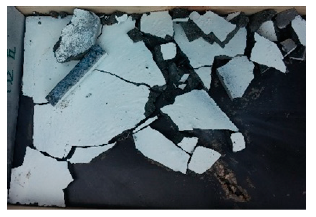
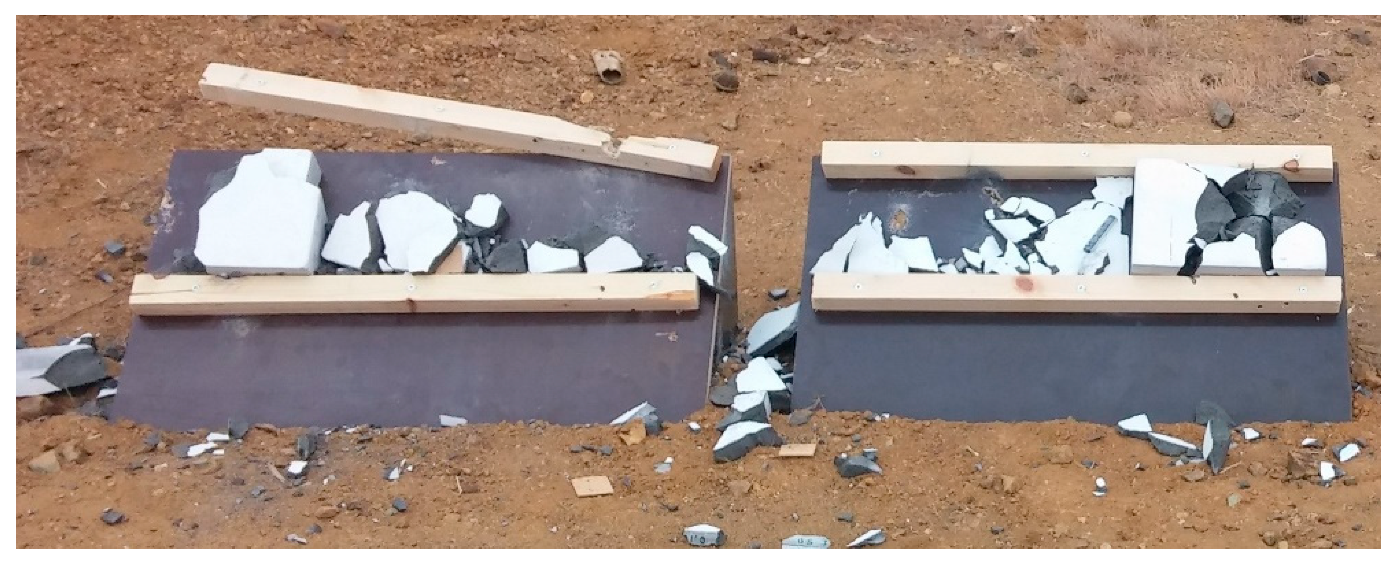
Slabs were subjected to projectile impact and the penetration depth, the volume loss, and the crater diameter were measured. The above measurements were selected because they can be directly compared with data found in the literature. Furthermore, slabs were categorized based on the three types of failure. In the next tables, the results from the projectile impact testing are shown for each mixture. The slabs from HSC and UHPC were broken into pieces and destroyed after projectile impact, as per failure type III (Figure 11). Therefore, it was not possible to conduct any measurements.
As shown in Table 3 and Table 4, the two mixtures with 2% steel fibers exhibited full penetration in all slabs of 15 mm and 30 mm thicknesses. In one of the four slabs of 50 mm thickness, there was not complete penetration with cracks at the rear face of the slab, failure type IIa. However, the material volume loss was greater than the other 50 mm thickness slab from the same mixture (2(0-2)/16/6) that exhibited perforation.
When the percentage of steel fibers increased from 2% to 6% and for mixture 6(5-1)/16/6 (see Table 5 and Table 6), complete penetration (failure type I) appeared in slabs with 15 mm thickness. In slabs with 30 mm thickness, failure type I appeared in three of the four slabs. All slabs with 50 mm thickness showed failure type II and the penetration depth did not exceed 1.5 cm. The material volume loss, from 30 mm to 50 mm slab thickness, was decreased for mixture 6(5-1)/16/6, from 51.3 cm3 to 10.1 cm3, on average. The use of high volume and the combination of two lengths steel fibers improved the resistance against projectile impact.
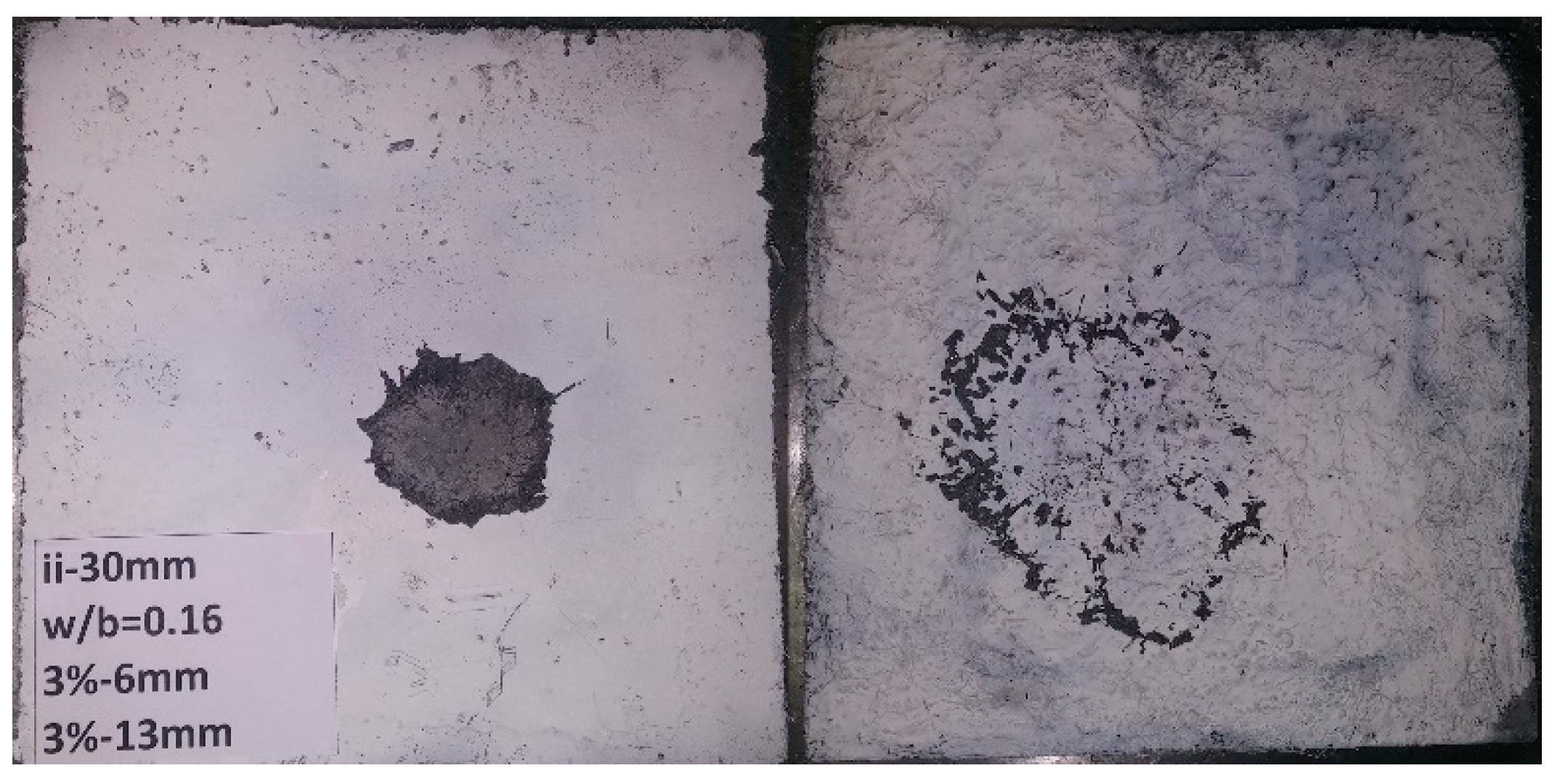
When 2% long steel fibers replaced short steel fibers (3:3 ratio for short to long fibers), mixture 6(3-3)/16/6 (see Table 7), perforation was only observed in slabs of 15 mm thickness. In slabs with thickness 30 mm and 50 mm, failure type IIa occurred. When the volume of long fibers increased and short fibers decreased in the mixture, the impact damage was reduced, the resulted material volume loss was 7.7 cm3 for 30 mm thickness slabs, on average.
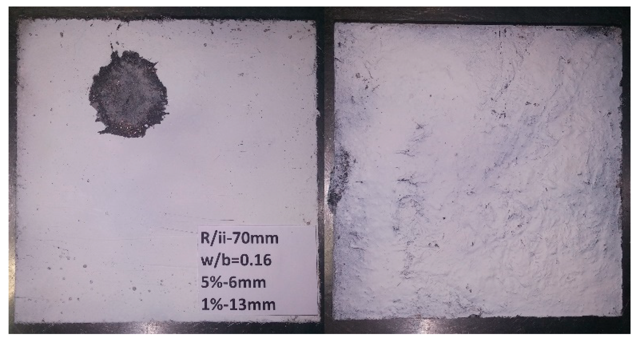
It is necessary to mention that slabs with a thickness of 70 mm and for mixtures with 6% volume of fibers did not suffer any damage (failure type IIb) at the rear face. For mixtures with 2% by volume, one of the two slabs that were tested exhibited cracks at the rear face. The thickness of the target slab combined with a mixture of high strength and ductility prevented the pull out at the rear face. The fibers lead to smaller crater volumes and prevent the ejection of concrete mass from the slab.
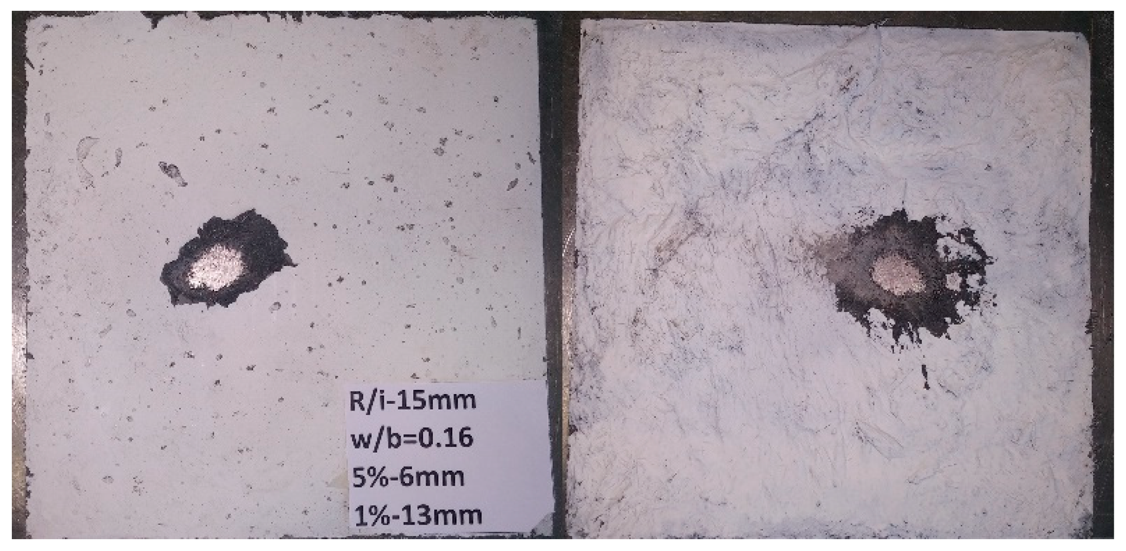
For 15 mm thickness slabs, there was perforation in all mixtures. Measurements of the average crater diameter at the center of the penetration (from the 2 slabs of each mixture) are presented in Table 8. For slabs with 2% per volume steel fibers, crater diameter was 24% smaller when w/b increased from 0.16 to 0.20. When the quantity of steel fibers increased from 2% to 6% by volume, the reduction of the crater was around 31%, on average. It is important to note that the highest reduction (36%) was exhibited by 6(3-3)/16/6 mixture. This confirms the benefits against the projectile impact of adding a high amount of fibers which helps to reduce the extent of cracking and damage. The fibers reduced crack propagation to the rest of the slab and the damage contained only at the point that the bullet hit the slab. Short length fibers prevent the development of multi cracks and long length fibers did not allow the crack width to extend and macro cracks to develop.
No failure occurred in 70 mm thickness slabs, in any of the mixtures. The damage extent due to projectile impact was defined by penetration depth, diameter of the crater at the front face, and material volume loss. The average measurement values are presented in Table 9. The average material volume loss for slabs with 2% steel fibers was increased by 84% and the average penetration depth by 48% when the w/b increased from 0.16 to 0.20. A reduction of these measurements was observed when the amount of fibers was increased from 2% to 6%. Specifically, the increase of steel fibers from 2% to 6%, 5:1 ratio short to long steel fibers, led to a decrease of average material volume loss by 28.0% and had a minor effect on the average penetration depth, 1.5% reduction. The substitution of short length fibers of 2% by volume with long length fibers in the mixture 6(3-3)/16/6 resulted in a reduction of average material volume loss by 45.6%, compared again with 2(0-2)/16/6. There was also a significant decrease in the average penetration depth by 49.7%. When w/b increased from 0.16 to 0.20 crater diameter increased by 3.8%. Slabs with 6% by volume fibers exhibited reduced crater diameter by 20% compared to slabs with 2% per volume steel fibers.
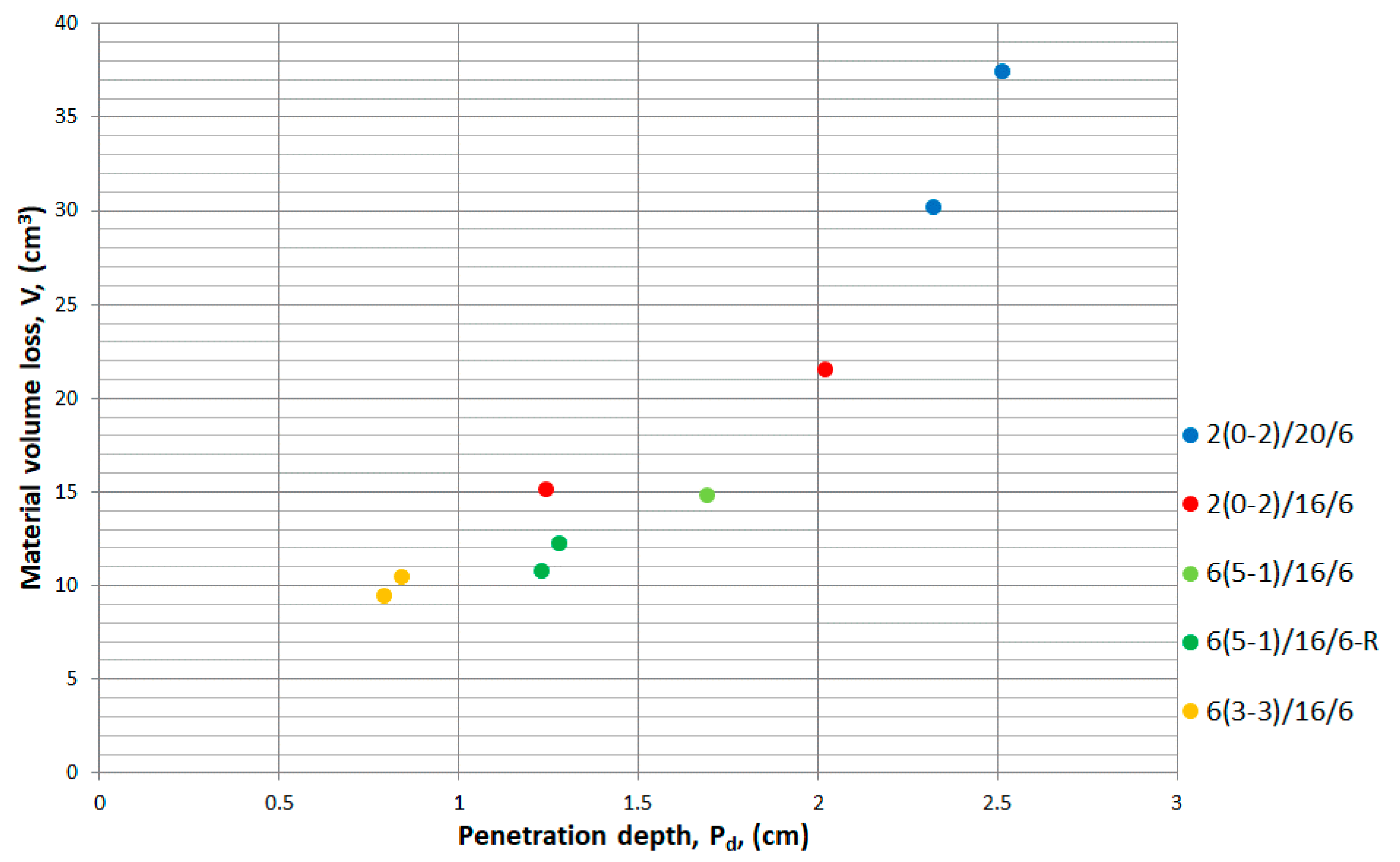
In Figure 12, the correlation between material volume loss and penetration depth is illustrated. Considering an approximately constant cone angle, the radius of the base is proportional to the penetration depth Pd and therefore the volume of the cone, that is the material volume loss V, can be expressed as α 1 3 π ( P d ) 2 P d . Consequently, a polynomial relation of a third degree is expected. Such a relationship seems to be supported by the experimental data points in Figure 12.
Based on Table 9 and Figure 12, the best performance was exhibited by 6(3-3)/16/6 slabs. When the bullet hit the slab, the energy of the bullet was transferred to the slab and the penetration process began. Almusallam et al. [21] described penetration procedure and wrote that: “It is believed that the compressive longitudinal waves generated by the impact propagated spherically into the concrete. When the wave reached the rear surface, it was reflected at normal incidence as a tensile wave. The superposition of the original compressive wave and the reflected tensile wave resulted in a fast decreasingly compressive and then increasingly tensile wave.” Cracks developed when the tensile stress wave was higher than the tensile strength of the concrete. The reflection of the tensile wave to compressive wave repeated and the damage of the concrete extended. This process continued until the tensile stress of the wave reduced to lower values than concrete tensile strength. Slabs with a thickness of 70 mm had no perforation because the elastic wave was reflected several times and this led to its weakening. Moreover, the mixture 6(3-3)/16/6 had the lower penetration depth because of its high tensile strength and ductility that prevented the damage to extend. The combination of short and long fibers prevented the crack propagation and consequently smaller crater damage and penetration depth occurred. In Figure 13, the correlation between penetration depth and compressive strength is presented, for slabs of 70 mm thickness.
The results are shown for each slab. Impact resistance does not depend only on compressive strength values. The UHPFRC mixtures were marked with different colors to depict also the effect of steel fibers and w/b to the impact behavior. It is generally accepted that penetration depth is reduced when compressive strength increases and this is confirmed by the results. Based on the experimental results, it seems that there is a linear correlation between them with a correlation coefficient, R
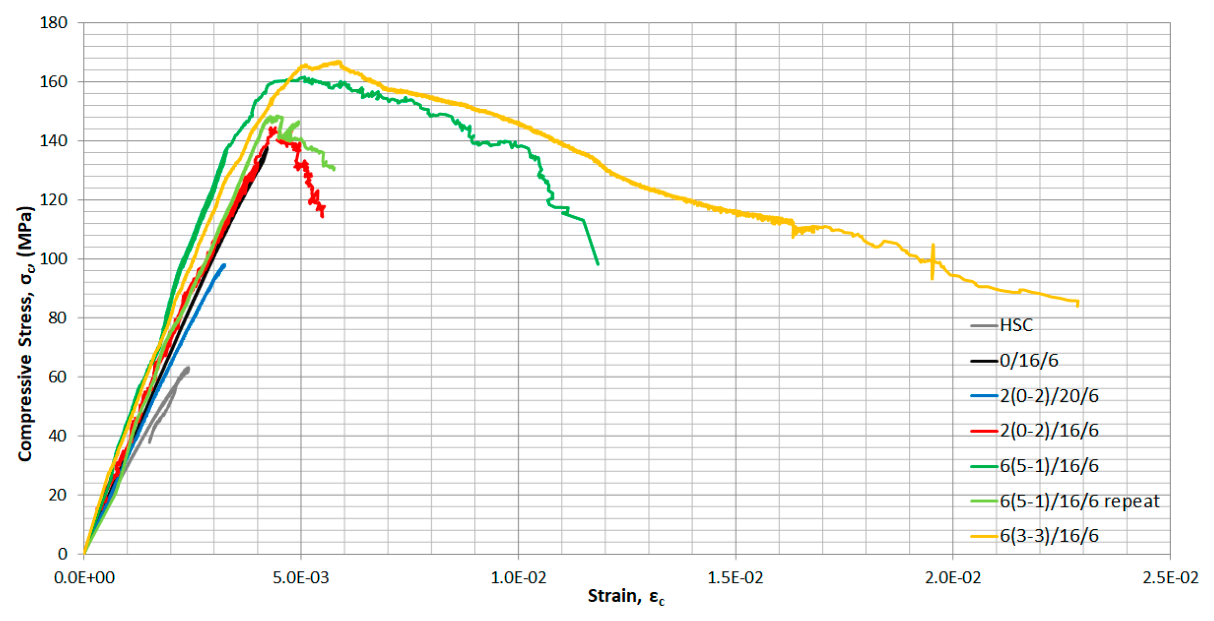
2, equal to 0.78. Further investigation is needed to confirm the linear correlation between penetration depth and compressive strength. Mixtures without fibers broke into pieces and do not appear in the figure. The addition of 2% fibers significantly enhanced the resistance to projectile impact loading. The high scattering of the test results was attributed to the low fiber volume combined with the inherent variability expected in such mixtures and the small size of the area participating in resisting the projectile impact. Mixtures with 6% of steel fibers had lower penetration depth and scattering in the results compared to mixtures with 2% fibers. Both 6% mixtures achieved compressive strength higher than 150 MPa but the mixture 6(3-3)/16/6 with equal volume of short and long length fibers was found to have the lowest penetration depth (
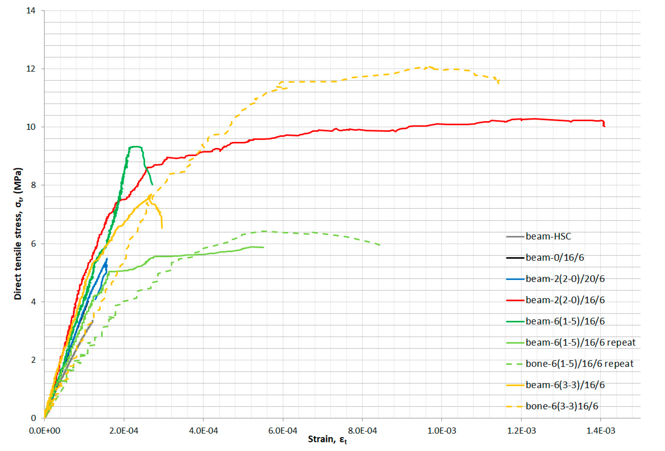
Table 9). It is important to note that 6(3-3)/16/6 exhibited the highest compressive and flexural strengths but also ductility (Table 2 and Figure 9). Zhang et al. [16] observed that “steel fibres reduced cracks propagation beyond the crater region, so that damage becomes confined to a localized area”. Steel fibers can manage to reduce crack propagation and that leads to a smaller impact load damage. Short fibers prevent multi cracks from developing and contain the damage near the cone. Long length fibers resist large crack propagation and consequently can prevent spalling and scabbing that leads to perforation As illustrated in Figure 14, the fibers did not fail at the damage surface, but were pulled out mainly due to their smooth surface and short length.
The projectile impact very quickly creates multi cracks and the matrix is converted to pieces. The severity of the impact exceeds the ability of the fibers to keep the concrete cohesive, hence the concrete is separated from the fibers creating a cone-shaped failure. At the surface of the cone, it seems that the fibers are still bonded on the matrix that was not destroyed. The fibers reduced the mass which was ejected and detached from the concrete slabs. Sovjak et al. [44,45] studied the effect of the fiber volume fraction and the fiber aspect ratio on the fracture energy. Their research proved that fracture energy increases when aspect ratio and volume fraction of fiber increases. Higher fracture energy leads to higher energy absorption and better resistance to projectile impact. The long fibers in the current research had an aspect ratio of 81.25, almost two times bigger than the aspect ratio of the short fibers (37.5). The mixtures 6(3-3)16/6 and 6(5-1)16/6 had the highest percentage by volume of fiber (6%), but the mixture 6(3-3)16/6 with the replacement of 2% per volume of short fiber with long fiber had additionally the highest fiber aspect ratio.
Máca et al. [20] used full metal-jacketed projectiles of 7.62 mm × 39 mm with 8.04 g mass and velocity of 710 m/s, Zhang et al. [16] used caliber 12.6 mm, with 15 g mass and velocity of 620–700 m/s and Kravanja and Sovják [14] used full metal-jacketed projectiles of 7.62 mm × 39 mm with 8.04 g mass and velocity of 710 m/s, tested slabs of UHPFRC with thickness 50 mm,150 mm, and 200 mm respectively and measured crater diameter and penetration depth. Kravanja and Sovják [14] used both deformable and non-deformable projectiles. During the impact process they observed that the soft lead core (deformable projectile) was completely destroyed and the non-deformable projectile rebounded while the non-deformable core and steel jacket separated. Máca et al. [20] also used two types of projectiles but results for penetration depth were presented only for the deformable projectile. Zhang et al.’s [16] projectile had no damage after the impact test. In this research, the projectile deformed after the impact test (Figure 4). In Figure 15, a comparison is presented between the experimental results from the above papers and the experimental results from this research.
Figure 15 data points correspond to average values from each mixture. Mixtures 2(0-2)/20/6, 2(0-2)/16/6, Máca et al. [20] with 1%, 2%, and 3%, and Kravanja and Sovják (deformable projectile) [14] with 0.125% 0.25%, 0.25%, 0.5%, 1%, and 2% per volume steel fibers have a penetration depth around 2 cm. Crater diameters from literature [14,20] vary between 5.5 and 8.5 cm and are higher than the crater diameters measured in this study which are around 5.0 cm. The difference observed could be attributed to the different experimental parameters involved. This experimental study used projectiles with higher mass and velocity than prior studies [14,20] that also used deformable projectiles. Other parameters are slab thickness, fiber percentage, distance from the target etc. Zhang et al. [16] with 1.5% per volume fibers and Kravanja and Sovják (non-deformable projectile) [14] presented higher values for penetration depth (around 3.5 cm) but crater diameter measurements vary along the same values as Máca et al. [20] with 1%, 2%, and 3% steel fibers and Kravanja and Sovják (deformable projectile) [14]. Zhang et al. in a recent research investigation [46] also came to the same conclusion that for the same material target and impact conditions, the penetration depth from deformable projectile is lower than the one from non-deformable projectile.
In literature, empirical formulae are proposed to calculate the penetration depth due to local impact [16,21,43,47,48,49,50,51]. R.P. Kennedy [51] refers to these empirical equations which are based on experimental test results and notes that “in nearly all of the tests the striking missile has been an essentially non-deformable projectile or bomb often made of armor-piercing steel, while the target has been a massive, non-deformable concrete target.” The experimental results of the present study are compared with three of these equations: Equation (1) recommended by the US Army Corps Engineers (ACE), Equations (2)–(4) from National Defence Research Committee (NDRC) modified by R.P. Kennedy [51], and Equations (5)–(8) by Almusallam et al. [21,47] who modified the NDRC equation in order to account for the effectiveness of the fibers. The original formulae for Equations (1) and (2)–(4) were in non-SI units. The equations presented below are in SI units [49].
P d d = 3.5 × 10 4 f c ( M d 3 ) d 0.215 V 0 1.5 + 0.5
G = 3.8 × 10 5 N M d f c ( V 0 d ) 1.8
G = ( P d 2 d ) 2   For   P d d 2
G = P d d 1   For   P d d > 2
G = 3.8 × 10 5 exp ( { 1 2 i = 1 n a i p i } 2.5 ) N M d f c ( V 0 d ) 1.8
x d = 2 G 0.5   For   G 1
x d = G + 1   For   G 1
a i = k i l i d i   E i E s
In all equations, Pd is the penetration depth (m), d is the diameter of the projectile (m), M is the projectile mass (kg), fc is the ultimate compressive strength of concrete (Pa), V0 is the projectile impacting velocity (m/s), and N is the nose shape factor, equal to 1.14 for a sharp nose. For equations (5)–(8), x = Pd and the fiber influence is calculated via pi which is the volume fraction of fibers and constant factor ai which is considered as a bond factor of fibers (ki)–0.8 for straight fibers, (li) length of fibers, (di) diameter of fibers, (Ei) modulus of elasticity for the different material type of fibers, and (Es) modulus of elasticity of steel fibers.
Characteristics of the weapon used for the impact tests in this study are presented in Section 2.3. Weapon characteristics used in this study and the ultimate compressive strength measured from cubical concrete specimens in this experimental program, see Table 2, were substituted into the empirical Equations (1)–(8) in order to calculate penetration depth. The empirical formulae were not used to describe the experimental results of this study because they were developed using data from non-deformable projectile impact. The experimental results in this study used deformable projectile. The presentation, in Figure 16, was made to show that penetration depth depends not only on the target properties but also on projectile deformation. Furthermore, Zhang et al. [46] concluded that for the same target material and impact conditions the penetration depth from deformable projectile is lower than from non-deformable projectile and proved that the difference depends on the relative effective hardness between target and projectile. There is a lack of equations to predict penetration depth for deformable projectile and UHPFRC targets. More data and further investigation are needed to develop an empirical model.
For HSC and UHPC (0/16/6), the results are shown in Table 10. According to the empirical formulae, the penetration depth for these 2 mixtures is over 7 cm which was the maximum slab thickness used in this study. This is consistent with the results of the experimental impact tests in the field. As mentioned above, all slabs constructed using HSC and UHPC (0/16/6) broke into pieces and had failure type III for all slab thicknesses.
For UHPFRC, the penetration depth from experimental impact tests in this study and the penetration depth calculated from empirical formulae are presented in Figure 16 as a function of the compressive strength. Empirical Equation (1) predicted similar penetration depths with Equation (2) for Pd/d > 2. In contrast, when Pd/d < 2, Equation (2) predicted almost half penetration depths. UHPFRC penetration depths from experimental tests in the field are two times lower than the predictions from the modified NDRC formula (Equation (2)) for low penetration depth, Pd/d < 2. This is expected because the formulae were developed for normal concrete and weapon velocities less than 310 m/s [16,48]. Equation (5), which takes into account fibers geometry and volume in the mixture, is the most accurate for predicting the performance of the specimens tested in this study. It is obvious that the penetration depth of an UHPFRC due to projectile impact does not depend only on compressive strength. High compressive strength offers smaller penetration depth but according to the results, penetration depth depends also on the amount of steel fibers, on the tensile strength and ductility of concrete, length and combination of steel fibers in the mixture and target thickness. Indeed, the mixture 6(3-3) with 3% by volume of short and 3% long length fibers was found to have the lowest penetration depth from all experimental results with real gunshot and the lowest according to Equation (5). As mentioned above, further experimental results are needed in order to derive an empirical formula for UHPFRC and deformable projectile impact.

4. Conclusions

Several conclusions can be drawn from the conducted research:
  • The addition of steel fibers to UHPC improved its mechanical properties and resistance to impact loading. The UHPC slabs were broken into pieces after projectile impact and the addition of 2% by volume steel fibers significantly improved its resistance to projectile impact. The damage was contained only at the point that projectile hit the slab and a cone shape failure appeared.
  • The average material volume loss for 70 mm thickness slabs with 2% steel fibers was increased by 84% and the average penetration depth by 48% when the w/b increased from 0.16 to 0.20.
  • For 70 mm thickness slabs, when the amount of steel fibers increased from 2% to 6%, 5:1 short to long steel fibers, the material volume loss decreased by 28.0%. From 2% to 6%, 3:3 short to long fibers, a significant decrease by 45.6% and 49.7% of average material volume loss and penetration depth, respectively, was exhibited.
  • When the ratio of short to long steel fibers changed to 3:3 from 5:1, the average penetration depth and material volume loss decreased by 48.9% and 24.5% respectively, for 70 mm thickness slab.
  • UHPFRC slabs with a thickness of 50 mm or higher, compressive strength of over 150 MPa, and containing 6% by volume fibers exhibited no penetration.
  • Empirical formulae overestimate penetration depth and need further experimental results to produce an empirical formula for UHPFRC and deformable projectiles.
It is obvious that penetration depth in an UHPFRC due to projectile impact does not depend only on compressive strength and amount of fibers, but it depends also on the tensile strength and ductility of concrete, length, and combination of steel fibers in the mixture and target thickness. It depends also on the relative characteristic properties between deformable projectile and target. Overall, the mixture with a composition 6(3-3)/16/6 exhibited the best mechanical characteristics and the best resistance to projectile impact loading. Only the 15 mm thickness slabs suffered perforation under projectile impact.

Author Contributions

Conceptualization, All; methodology, All; validation, All; formal analysis, A.L.M.; investigation, A.L.M.; resources, A.L.M.; data curation, All; writing—original draft preparation, A.L.M.; writing—review and editing, All; supervision, M.F.P. and K.G.T.; project administration, M.F.P. and K.G.T. All authors have read and agreed to the published version of the manuscript.

Funding

This research received no external funding.

Institutional Review Board Statement

Exclude this statement.

Informed Consent Statement

Exclude this statement.

Data Availability Statement

Data is contained within the article.

Conflicts of Interest

The authors declare no conflict of interest.

References

  1. Clifton, J.; Knab, L. Impact testing of concrete. Cem. Concr. Res. 1983, 13, 541–548. [Google Scholar] [CrossRef]
  2. Godfrey, K.A., Jr. Concrete strength record jumps 36%. Civ. Eng. 1989, 57, 84–86. [Google Scholar]
  3. Hanchak, S.J.; Forrestal, M.J.; Young, E.R.; Ehrgott, J.Q. Perforation of concrete slabs with 48MPa (7ksi) and 140MPa (20ksi) unconfined compressive strengths. Int. J. Impact. Eng. 1992, 12, 1–7. [Google Scholar] [CrossRef]
  4. Hassan, A.; Jones, S.W.; Mahmud, G. Experimental test methods to determine the uniaxial tensile and compressive behav-iour of ultra high performance fibre reinforced concrete (UHPFRC). Constr. Build. Mater. 2012, 37, 874–882. [Google Scholar] [CrossRef]
  5. Richard, P.; Cheyrezy, M. Composition of reactive power concretes. Cem. Concr. Res. 1995, 25, 1501–1511. [Google Scholar] [CrossRef]
  6. Yu, R.; Spiesz, P.; Brouwers, H.J.H. Mix design and properties assessment of ultra-high performance fibre reinforced con-crete (UHPFRC). Cem. Concr. Res. 2014, 56, 29–39. [Google Scholar] [CrossRef]
  7. Kazemi, S.; Lubell, A.S. Influence of specimen size and fiber content on mechanical properties of ultra-high-performance fiber-reinforced concrete. ACI Mater. J. 2012, 109, 675–684. [Google Scholar]
  8. Máca, P.; Sovják, R.; Vavřiník, T. Experimental investigation of mechanical properties of UHPFRC. Procedia Eng. 2013, 65, 14–19. [Google Scholar] [CrossRef] [Green Version]
  9. Karihaloo, B.L.; Benson, S.D.P. CARDIFRC—Development and mechanical properties. Part I: Development and workability. Mag. Concr. Res. 2005, 57, 347–352. [Google Scholar]
  10. Petrou, M.F.; Trezos, K.G.; Mina, A.L. Design of UHPFRC mixtures to be used in structures subjected to impact loads. In Proceedings of the 27th Biennial National Conference of the Concrete Institute of Australia in Conjuction with the 69th RILEM Week, Melbourne, Australia, 30 August–2 September 2015. [Google Scholar]
  11. Mina, A.L.; Petrou, M.F.; Trezos, K.G. Experimental analysis for the development of an UHPFRC. In Proceedings of the Concrete Solutions 2016 6th International Conference on Concrete Repair, Thessaloniki, Greece, 20–23 June 2016. [Google Scholar]
  12. Nicolaides, D.; Kanellopoulos, A.; Petrou, M.; Savva, P.; Mina, A. Development of a new ultra high performance fibre rein-forced cementious composite (UHPFRCC) for impact and blast protection of structures. Constr. Build. Mater. 2015, 95, 667–674. [Google Scholar] [CrossRef]
  13. Scott, D.A.; Long, W.R.; Moser, R.D.; Green, B.H.; O’Daniel, J.L.; Williams, B.A. Impact of Steel Fiber Size and Shape on the Mechanical Properties of Ultra-High Performance Concrete; ERDC: Vicksburg, MS, USA, 2015; pp. 15–22. [Google Scholar]
  14. Kravanja, S.; Sovják, R. Ultra-high-performance Fibrereinforced concrete under high-velocity projectile impact. Part I. Experiments. Acta Polytech. 2018, 58, 232–239. [Google Scholar] [CrossRef]
  15. Dancygier, A.; Yankelevsky, D. High strength concrete response to hard projectile impact. Int. J. Impact. Eng. 1996, 18, 583–599. [Google Scholar] [CrossRef]
  16. Zhang, M.; Shim, V.; Lu, G.; Chew, C. Resistance of high-strength concrete to projectile impact. Int. J. Impact. Eng. 2005, 31, 825–841. [Google Scholar] [CrossRef]
  17. O’ Neil, E.F.; Neeley, B.D.; Cargile, J.D. Tensile properties of very-high-strength concrete for penetration-resistant structures. Shock Vib. 1999, 6, 237–245. [Google Scholar] [CrossRef] [Green Version]
  18. Kravanja, S.; Sovják, R.; Konrád, P.; Zatloukal, J. Penetration Resistance of Semi-infinite UHPFRC Targets with various Fiber Volume Fractions against Projectile Impact. Procedia Eng. 2017, 193, 112–119. [Google Scholar] [CrossRef]
  19. Bludau, C.; Keuser, M.; Kustermann, A. Perforation resistance of high-strength concrete panels. ACI Struct. J. 2006, 103, 188–195. [Google Scholar]
  20. Máca, P.; Sovják, R.; Konvalinka, P. Mix design of UHPFRC and its response to projectile impact. Int. J. Impact Eng. 2014, 63, 158–163. [Google Scholar] [CrossRef]
  21. Almusallam, T.H.; Siddiqui, N.A.; Iqbal, R.A.; Abbas, H. Response of hybrid-fiber reinforced concrete slabs to hard projectile impact. Int. J. Impact. Eng. 2013, 58, 17–30. [Google Scholar] [CrossRef]
  22. Kim, G.-Y.; Choi, J.-I.; Park, S.-E.; Kim, H.; Lee, Y.; Lee, B.Y. Response of UHPFRC and HDFRC under static and high-velocity projectile impact loads. Constr. Build. Mater. 2018, 188, 399–408. [Google Scholar] [CrossRef]
  23. Feng, J.; Gao, X.; Li, J.; Dong, H.; Yao, W.; Wang, X.; Sun, W. Influence of fiber mixture on impact response of ul-tra-high-performance hybrid fiber reinforced cementitious composite. Compos. Part B 2019, 163, 487–496. [Google Scholar] [CrossRef]
  24. Lai, J.; Yang, H.; Wang, H.; Zheng, X.; Wang, Q. Properties and mondeling of Ultra-High_Performance Concrete subjected to multiple bullet impacts. J. M. Civil. Eng. 2018, 30, 1–6. [Google Scholar]
  25. Millard, S.G.; Molyneaux, T.C.K.; Barnett, S.J.; Gao, X. Dynamic enhancement of blast-resistant ultra high performance fibrereinorced concrete under flexural and shear loading. Int. J. Impact. Eng. 2010, 37, 405–413. [Google Scholar] [CrossRef] [Green Version]
  26. Habel, K.; Gauvreau, P. Response of ultra-high performance fiber reinforced concrete (UHPFRC) to impact and static loading. Cem. Concr. Compos. 2008, 30, 938–946. [Google Scholar] [CrossRef]
  27. Banthia, N.P.; Mindess, S.; Bentur, A. Impact behaviour of concrete beams. Mater. Struct. 1987, 20, 293–302. [Google Scholar] [CrossRef]
  28. Ranade, R.; Li, V.C.; Heard, W.F.; Williams, B.A. Impact resistance of high strength-high ductility concrete. Cem. Concr. Res. 2017, 98, 24–35. [Google Scholar] [CrossRef]
  29. Bindiganavile, V.; Banthia, N.; Aarup, B. Impact response of ultra-high-strength fiber-reinforced cement composite. ACI Mater. J. 2002, 99, 543–548. [Google Scholar]
  30. Habel, K.; Gauvreau, P. Behavior of Reinforced and Posttensioned Concrete Members with a UHPFRC Overlay under Impact Loading. J. Struct. Eng. 2009, 135, 292–300. [Google Scholar] [CrossRef]
  31. Yu, R.; Spiesz, R.P.; Brouwers, H.H.J. Dynamic performance of a sustainable ultra-high performance Fibre Reinforced Concrete (UHPFRC) under high velocity projectile impact. In Tagungsbericht/IBAUSIL, 19; Internationale Baustofftagung: Weimar, Germany, 2015. [Google Scholar]
  32. Sovják, R.; Vavřiník, T.; Zatloukal, J.; Máca, P.; Mičunek, T.; Frydrýn, M. Resistance of slim UHPFRC targets to projectile impact using in-service bullets. Int. J. Impact. Eng. 2015, 76, 166–177. [Google Scholar] [CrossRef]
  33. Lok, T.S.; Zhao, P.J. Impact Response of Steel Fiber-Reinforced Concrete Using a Split Hopkinson Pressure Bar. J. Mater. Civ. Eng. 2004, 16, 54–59. [Google Scholar] [CrossRef]
  34. Lai, J.; Sun, W. Dynamic behaviour and visco-elastic damage model of ultra-high performance cementious composite. Cem. Concr. Res. 2009, 39, 1044–1051. [Google Scholar] [CrossRef]
  35. Khosravani, M.R.; Weinberg, K. A review on split Hopkinson bar experiments on the dynamic characterisation of concrete. Constr. Build. Mater. 2018, 190, 1264–1283. [Google Scholar] [CrossRef]
  36. Yu, R.; Van Beers, L.; Spiesz, P.; Brouwers, H. Impact resistance of a sustainable Ultra-High Performance Fibre Reinforced Concrete (UHPFRC) under pendulum impact loadings. Constr. Build. Mater. 2016, 107, 203–215. [Google Scholar] [CrossRef]
  37. Li, P.P.; Yu, L.Q. Responses and post-impact properties of ultra-high performance fibre reinforced concrete under pendulum impact. Compos. Struct. 2019, 208, 806–815. [Google Scholar] [CrossRef]
  38. Konrád, P.; Sovják, R. Experimental procedure for determination of the energy dissipation capacity of ultra-high-performance fibre-reinforced concrete under localized impact loading. Int. J. Prot. Struct. 2019, 10, 251–265. [Google Scholar] [CrossRef]
  39. Nicolaides, D.; Kanellopoulos, A.; Savva, P.; Petrou, M. Experimental field investigation of impact and blast load resistance of ultra high performance fibre reinforced cementious composites (UHPFRCCs). Constr. Build. Mater. 2015, 95, 566–574. [Google Scholar] [CrossRef]
  40. Mina, A.L.; Trezos, K.G.; Petrou, M.F. Optimizing the mechanical properties of Ultra High Performance Fibre Reinforced Concrete to increase its resistance to projectile impact. Materials 2021. manuscript in preparation to be submitted. [Google Scholar]
  41. Mina, A.L.; Trezos, K.G.; Petrou, M.F. Mechanical Properties of Ultra High Performance Fibre Reiforced Concrete and Its Response to Impact Loading. In Advanced Materials for Defense; Fangueiro, R., Rana, S., Eds.; Springer: Cham, Switzerland, 2020; Volume 4, pp. 71–78. [Google Scholar]
  42. Kneubuehl, B.P.; Coupland, R.M.; Rothschild, M.A.; Thali, M.J. Wound Ballistics Basics and Applications. Springer: Berlin/Heidelberg, Germany; New York, NY, USA, 2008. [Google Scholar]
  43. Vossoughi, F.; Ostertag, C.P.; Monteiro, P.J.M.; Johnson, G.C. Resistance of concrete protected by fabric to projectile impact. Cem. Concr. Res. 2007, 37, 96–106. [Google Scholar] [CrossRef]
  44. Sovják, R.; Máca, P.; Imlauf, T. Effect of fibre aspect ratio and fibre volume fraction on the effective fracture energy of ul-tra-high-performance fibre-reinforced concrete. Acta Polytech. 2016, 56, 319–327. [Google Scholar] [CrossRef]
  45. Sovják, R.; Máca, P.; Imlauf, T. Effect of Fibre Length on the Fracture Energy of UHPFRC. Procedia Eng. 2017, 193, 74–79. [Google Scholar] [CrossRef]
  46. Zhang, F.; Poh, L.H.; Zhang, M.-H. Resistance of cement-based materials against high-velocity small caliber deformable projectile impact. Int. J. Impact Eng. 2020, 144, 103629. [Google Scholar] [CrossRef]
  47. Almusallam, T.H.; Abadel, A.A.; Al-Salloum, Y.A.; Siddiqui, N.A.; Abbas, H. Effectiveness of hybrid-fibers in improving the impact resistance of RC slabs. Int. J. Impact Eng. 2015, 81, 61–73. [Google Scholar] [CrossRef]
  48. Williams, M.S. Modeling of Local Impact Effects on Plain and Reinforced Concrete. ACI Struct. J. 1994, 91, 178–187. [Google Scholar] [CrossRef]
  49. Li, Q.M.; Reid, S.R.; Wen, H.M.; Telford, A.R. Local impact effects of hard missiles on concrete targets. Int. J. Impact Eng. 2005, 32, 224–284. [Google Scholar] [CrossRef]
  50. Kravanja, S.; Sovják, R. Ultra-High-Performance Fibrereinforced Concrete under High-Velocity Projectile Impact—Part 2. Applicability of Prediction Models. Acta Polytech. 2018, 58, 355–364. [Google Scholar] [CrossRef] [Green Version]
  51. Kennedy, R. A review of procedures for the analysis and design of concrete structures to resist missile impact effects. Nucl. Eng. Des. 1976, 37, 183–203. [Google Scholar] [CrossRef]
Figure 1. Normal concrete wall under projectile impact.
Buildings 11 00063 g001
Figure 2. Slabs specimens in the field.
Buildings 11 00063 g002
Figure 3. Initial shape of the bullet.
Buildings 11 00063 g003
Figure 4. Bullet after impact.
Buildings 11 00063 g004
Figure 5. Failure type I—full penetration of the slab (front face at the left and rear face at the right). Reprinted/adapted by permission from Springer Nature: Springer Nature Switzerland AG, Mina, A.L.; Trezos, K.G.; Petrou, M.F. Mechanical Properties of Ultra High Performance Fibre Reiforced Concrete and Its Response to Impact Loading. In Advanced Materials for Defense; Fangueiro, R.; Rana, S., Eds.; Springer: Cham, Switzerland, 2020; Volume 4, pp. 71–78.
Buildings 11 00063 g005
Figure 6. Failure type IIa (front face at the left and rear face at the right).
Buildings 11 00063 g006
Figure 7. Failure type IIb (front face at the left and rear face at the right). Reprinted/adapted by permission from Springer Nature: Springer Nature Switzerland AG, Mina, A.L.; Trezos, K.G.; Petrou, M.F. Mechanical Properties of Ultra High Performance Fibre Reiforced Concrete and Its Response to Impact Loading. In Advanced Materials for Defense; Fangueiro, R.; Rana, S., Eds.; Springer: Cham, Switzerland, 2020; Volume 4, pp. 71–78.
Buildings 11 00063 g007
Figure 8. Failure type III. Reprinted/adapted by permission from Springer Nature: Springer Nature Switzerland AG, Mina, A.L.; Trezos, K.G.; Petrou, M.F. Mechanical Properties of Ultra High Performance Fibre Reiforced Concrete and Its Response to Impact Loading. In Advanced Materials for Defense; Fangueiro, R.; Rana, S., Eds.; Springer: Cham, Switzerland, 2020; Volume 4, pp. 71–78.
Buildings 11 00063 g008
Figure 9. Compressive stress–strain curves from cylinder compression test.
Buildings 11 00063 g009
Figure 10. Direct tensile stress–strain curves from beams and bone-shaped specimens.
Buildings 11 00063 g010
Figure 11. Slabs from mixture 0/16/6 (ultra-high performance concrete, UHPC) and high strength concrete (HSC) after projectile impact test.
Buildings 11 00063 g011
Figure 12. Correlation between material volume loss, V and penetration depth, Pd.
Buildings 11 00063 g012
Figure 13. Correlation between penetration depth and compression strength for 70 mm thick slabs.
Buildings 11 00063 g013
Figure 14. Damage surface.
Buildings 11 00063 g014
Figure 15. Comparison with literature of penetration depth (Pd) and crater diameter (D).
Buildings 11 00063 g015
Figure 16. Comparison of experimental results of ultra-high performance fiber reinforced concrete (UHPFRC) mixtures (70 mm slabs) from impact and empirical formulas.
Buildings 11 00063 g016
Table 1. Mixture design.
Materials (kg/m3)HSC0/16/62(0–2)/16/62(0–2)/20/66(5–1)/16/66(3–3)/16/6
Cement 42.540000000
Cement 52.50880880880880880
Microsilica20220220220220220
Steel fibers 6 mm0000400240
Steel fibers 13 mm0016016080240
Diabase aggregates 8/2048800000
Diabase aggregates 4/1048500000
Recrystallized limestone sand 0/463600000
Diabase sand 0/418400000
Calcarenite sand 125–250 μm0475475475475475
Calcarenite sand 250–500 μm0358358358358358
Water160176176220176176
Superplasticizer6.16767676767
Table 2. Ultimate compressive strength from cubes and indirect tensile strength with the corresponding deflection.
MixtureUltimate Compressive Strength from Cubes (MPa)Ultimate Flexural Strength (MPa)Corresponding Deflection (mm)
HSC61.18.150.05
0/16/6124.013.20.08
2(0-2)/20/6134.129.0-
2(0-2)/16/6155.826.60.72
6(5-1)/16/6176.731.70.53
6(5-1)/16/6-R167.027.30.53
6(3-3)/16/6187.634.20.86
Table 3. Projectile impact results for mixture 2(0-2)/20/6.
Dimensions of Slab (mm × mm)Thickness of Slab (mm)Failure TypePenetration Depth Pd (cm)Material Volume Loss V (cm3)
200 × 20015I1.5014.1
200 × 20015I1.5024.5
200 × 20030I3.0041.9
200 × 20030I3.0089.7
200 × 20050I5.0049.8
200 × 20050I5.0096.1
200 × 20070IIa2.5137.5
200 × 20070IIb2.3230.2
Table 4. Projectile impact results for mixture 2(0-2)/16/6.
Dimensions of Slab (mm × mm)Thickness of Slab (mm)Failure TypePenetration Depth Pd (cm)Material Volume Loss V (cm3)
200 × 20015Ι1.5037.2
200 × 20015Ι1.5035.7
200 × 20030Ι3.0059.1
200 × 20030Ι3.0069.2
200 × 20050Ι5.0066.0
200 × 20050IIa1.1487.1
200 × 20070IIa2.0221.6
200 × 20070IIb1.2415.2
Table 5. Projectile impact results for mixture 6(5-1)/16/6.
Dimensions of Slab (mm × mm)Thickness of Slab (mm)Failure TypePenetration Depth Pd (cm)Material Volume Loss V(cm3)
200 × 20015Ι1.5015.5
200 × 20015Ι1.5027.6
200 × 20030Ι3.0060.5
200 × 20030Ι3.0087.7
200 × 20050IIa1.4016.1
200 × 20050IIa0.706.6
200 × 20070IIb1.6914.9
Table 6. Projectile impact results for mixture 6(5-1)/16/6-R.
Dimensions of Slab (mm × mm)Thickness of Slab (mm)Failure TypePenetration Depth Pd (cm)Material Volume Loss V (cm3)
200 × 20015I1.5015.1
200 × 20015I1.50-
200 × 20030IIa0.935.8
200 × 20030I3.00-
200 × 20050IIa1.2111.3
200 × 20050IIa0.856.4
200 × 20070IIb1.2812.3
200 × 20070IIb1.2310.8
Table 7. Projectile impact results for mixture 6(3-3)/16/6.
Dimensions of Slab (mm × mm)Thickness of Slab (mm)Failure TypePenetration Depth Pd (cm)Material Volume Loss V (cm3)
200 × 20015Ι1.5028.7
200 × 20015Ι1.5025.1
200 × 20030IIa0.986.7
200 × 20030IIa0.928.6
200 × 20050IIa1.3013.1
200 × 20050IIa1.4321.4
200 × 20070IIb0.799.5
200 × 20070IIb0.8410.5
Table 8. Average crater diameter for 15 mm thickness slabs for each mixture.
MixtureThickness of Slab (mm)Centre Crater Diameter D (cm)
2(0–2)/20/6152.5
2(0–2)/16/63.2
6(5–1)/16/62.4
6(5–1)/16/6-R2.3
6(3–3)/16/62.1
Table 9. Projectile impact results for 70 mm thickness slabs for each mixture.
MixtureThickness of Slabs (mm)Average Penetration Depth Pd (cm)Average Material Volume Loss V (cm3)Average Front Face Crater Diameter D (cm)
2(0–2)/20/6702.4233.95.21
2(0–2)/16/61.6318.45.02
6(5–1)/16/61.6914.94.34
6(5–1)/16/6-R1.5211.63.88
6(3–3)/16/60.8210.04.07
Table 10. Penetration depth for mixtures 0/16/6 and HSC from empirical equations.
Mix DesignUltimate Compressive Strength fc (MPa)Penetration depth Pd (cm) from Empirical Equation (1) (V0 = 800 m/s)Penetration Depth Pd (cm) from Empirical Equation (2) (V0 = 800 m/s)
HSC61.115.115.3
UHPC 0/16/6124.010.611.0
Publisher’s Note: MDPI stays neutral with regard to jurisdictional claims in published maps and institutional affiliations.

