
Damage Detection in Multiple RC Structures Based on Embedded Ultrasonic Sensors and Wavelet Transform


1
NeoStrain Sp.z.o.o., Lipowa 3, 30-702 Kraków, Poland
2
Bundesanstalt für Materialforschung und-Prüfung (BAM), Unter den Eichen 87, 12205 Berlin, Germany
*
Author to whom correspondence should be addressed.
†
These authors contributed equally to this work.
Buildings 2021, 11(2), 56; https://doi.org/10.3390/buildings11020056
Submission received: 31 December 2020
/
Revised: 31 January 2021
/
Accepted: 1 February 2021
/
Published: 7 February 2021
(This article belongs to the Collection Structural Dynamics and Analysis of Civil Structures and Engineering Materials)
Abstract
:This paper summarizes the results of research aimed at assessing cracks in reinforced concrete structures using embedded ultrasonic sensors. The diffuse ultrasonic waves were considered to evaluate the health status of the tested structures. There are different algorithms used to detect cracks in the structure, but most studies have been performed on benchmark reinforced concrete (RC) structures and in laboratory conditions. Since there were difficulties with the validity of damage detection in real structures in the presence of environmental changes and noises, the application of advanced signal processing methods was necessary. Therefore, the wavelet transform was applied to process ultrasonic signals acquired from multiple civil structures. It is shown that the ultrasonic sensors with an applied wavelet transform algorithm on collected signals can successfully detect cracks in the laboratory as well as in a real environment. Experimental results showed a perfect match for detecting damage and quasi-static load in the presence of environmental changes. The results were confirmed with other techniques. In addition, designing an extra filter for removing noises can be avoided by using the applied algorithms. The obtained results confirmed that diffuse ultrasonic sensor methodology with the proposed algorithm is useful and effective in monitoring real RC structures, and it is better than traditional techniques.
1. Introduction
The aging of infrastructure, especially made of reinforced concrete (RC), has gained noticeable attention in academia as well as in industry, due to the degradation of concrete properties and impossibility to withstand their designed structural life. The performance of the concrete structures changes with time as it is a heterogeneous material with non-linear, elastic properties. Therefore, material degradation is an important issue for different structures, caused mainly by their quasi-static and dynamic loading, deterioration, effect of temperature, and humidity. Continuous environmental and operational loadings, such as temperature and traffic, could result in progressive and continuous micro cracks, which lead to increased permanent deflections and decreased stiffness of the structure [1]. For this reason, the maintenance of structures is often performed to keep structural integrity. Therefore, non-destructive testing (NDT) is a popular approach used for diagnosis of such structures since it is significant to monitor structures in a timely manner, as repairing structures is less expensive compared to cost of any incident due to degradation of material [2]. Therefore, monitoring structures can prevent incidents that also save lives.
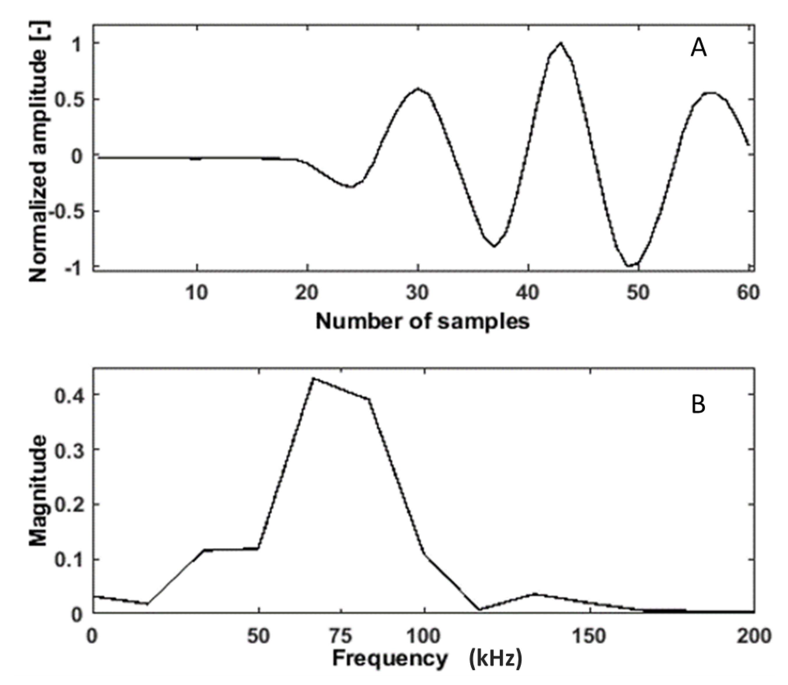
There are several NDT techniques commercially available in the market [3]. Ultrasonic pulse velocity (UPV) and Acoustic emission (AE) are the most reliable techniques that are currently used for diagnosis of RC structures [4,5]. Lu et al. [4] showed a high probability of detecting damage with temperature variation. Although AE is reliable technique that gives information much earlier than the visible opening of cracks, the interpretation of observed AE events is always a difficult task. Hence, it is difficult to distinguish AE events (due to microcracks) from background noises during the initial stage of loading. This is because most AE events occur just before the propagation of microcracks [6]. On the other hand, the active techniques based on using ultrasonic sensors are more reliable to detect cracks due to the relationship between ultrasonic wave propagation and initiation of cracks [7]. However, the traditional UPV technique has some limitations, as it needs a trained operator and is difficult for continuous monitoring [8]. To overcome these limitations, BAM (Bundesanstalt für Materialforschung und -prüfung) designed new embedded ultrasonic sensors which were manufactured by Acoustic Control Systems company, Moscow, Russia [9]. These new sensors are easy to install during concreting procedures and also on existing civil structures. The uniqueness of these sensors is their low-frequency band with the center frequency of 62 kHz and bandwidth of 100 kHz, compared to typical ultrasonic sensors for testing and monitoring of concrete structures available in the market. This is suitable for most of the structures, as the size of aggregates is less than the wavelength. The exemplary time and frequency domain of first arrivals from a signal is shown in Figure 1. The ultrasonic guided waves have been used for many structural health monitoring (SHM) systems. However, the guided wave is more suitable for steel structures. The diffuse ultrasonic wave is a very promising method for structural (RC structure) change detection, as a signal coming from a longer path contains more information compared to the first arrival [10].
These techniques developed for diagnosis of structures often extract raw signals as a response of a structure, and then features are extracted from these raw signals in order to continue diagnostic process and/or its enhancement. There are different signal processing algorithms that can be found and applied in order to extract damage-sensitive features. Signal processing techniques cover those of time, frequency, time–frequency domains, and physics-based techniques [11,12,13,14]. Lu and Michaels [11] extracted multiple features based on time domain. In another study, Rucka and Wilde [12] extracted features from the time domain signals to detect the splitting failure of the reinforced concrete beams also shown visual representation using a continuous wavelet transform (CWT). On the other hand in this study [13], the authors used wavelet packet energy to detect damage in the concrete beam. Liu et al. [15] presented the novel approach for vibration-based damage detection using an Autoregressive (AR) Model. A similar approach used for monitoring of RC structures and based on the AR coefficient can be found in [16]. Another approach is based on a cross-correlation function used for damage detection in steel beams under varying temperatures [17]. Frequency domain analysis is considered as an efficient technique for analyzing non-stationary signals for structural damage detection [18]. Cheraghi et al. [19] applied the Fast Fourier transform (FFT) to detect damage in pipes. The main deficiency of these approaches is their low sensitivity to signal disturbances caused by initiation and propagation of small structural damage. The short time Fourier transform (STFT) has been used to detect local damage in bearing [20], which, by the principle of signal analysis, is similar to the considered range of problems. The disadvantage of STFT is its small frequency resolution, however, low frequency can be hardly represented with a small window. Due to the Heisenberg principle, STFT has no multi-scale properties, which makes it impossible to detect low- and high-frequency events in the signal simultaneously. This problem can be overcome by application of the wavelet transform. Yan et al. [21] used energy spectrum of signals analyzed with wavelet transform to evaluate the ability of detecting cracks in a honeycomb sandwich plate by using a natural frequency and dynamic response. Gentile and Messina [22] used CWT to detect opening of cracks in beam structures. In [23], the authors presented damage detection in concrete using Fast Fourier transform (FFT) and CWT. In [24], the author presents an overview of vibration based damage detection using Discrete wavelet transform (DWT) and CWT. On the other hand, CWT was used to detect damage in concrete dams [25]. Epasto et al. [26] performed CWT-based analysis on the impact-echo method to detect fire-based damage in concrete. On the basis of the literature findings [13,23,25,26], it can be assumed that wavelet transform is most sensitive for damage detection in concrete structures.
The progressive degradation mechanisms in RC structures make it reliable and economically effective to develop and apply SHM systems based on the mentioned measurement equipment and further processing techniques. One of the main challenges of different NDT techniques is to transfer sensing and damage detection technologies from the laboratory environment to real structures. Often, it can be seen that most of the signal processing approaches applied for damage detection have some limitations in detecting damage in real structures due to the influence of noises and temperature [27]. In [28], the authors presented a noise reduction method for CODA wave analysis in bridge monitoring using the double-notch filter. The designing of the extra filter is always challenging and needs more processing time and power. Therefore, the feature extraction method that can detect damage by reducing noises in the presence of environmental changes is more effective. This problem is one of those which remains open in structural diagnostics.
This paper presents an active technique for damage detection of multiple structures using embedded ultrasonic sensors. The proposed damage detection technique uses the CWT and non-decimated wavelet transform (NDWT)-based signal processing methods to extract features from raw ultrasonic signals over a specific area to assess the presence of changes/damage. It is very important to keep measurement precision for damage detection in reinforced concrete structures from a practical point of view. Therefore, NDWT is a modified version of DWT that can keep better resolution due to its shift-invariance nature that allows for better damage detection [24]. The developed methods were applied to raw signals acquired from different types of structures to confirm the effectiveness of the proposed approach. For this above experimental purpose, benchmark RC structures that initiate cracks to its failure, and artificially create a damaged, real reference structure, were considered. The proposed signal processing approach was used to extract damage-/change-related features in both structures and provide suitability of the sensing system for real structures. The rest of the paper is organized as follows. In Section 2, the methodology with proposed features is defined. In Section 3, the types of considered structures and experimental setups are described, then the signal acquisition approach is explained. In Section 4, the feature is evaluated and compared with traditional techniques. The whole paper is summarized in Section 5.
2. Methodology
In this study, the load was applied on to RC structures, and the relative frequency changes between reference and stressed states were obtained.
2.1. Theoretical Background on Propagation of Ultrasonic Waves
To predict the strength of concrete, measurements of the Rayleigh wave and the skimming longitudinal wave velocities are used.
The velocity of surface Rayleigh waves is given in Equation (2):
where and are the velocity of sound for longitudinal and Rayleigh waves, E is the Young’s modulus, is the material density, and is the Poisson’s ratio. Equations (1) and (2) relate wave velocities with elastic parameters. Therefore, the propagation of waves is strongly affected by the elastic properties and density of constituent materials [29].
The relationship between stress/strain and wave velocity is known as the acoustoelastic effect. From the previous paragraph, one can see how the wave velocity and Young’s modulus are derived from the stress–strain relationship. The simplified linear elastic assumption would be insufficient for a real structural quantitative test. However, these factors can be reduced using a nonlinear approach, i.e., acoustoelasticity theory. The acoustoelasticity theory was developed in 1953 by Hughes and Kelly [30], expanding on Murnaghan’s laws of nonlinear elasticity [31]. The speed of elastic ultrasonic longitudinal and shear waves propagating through the solid depends on the elastic deformation of the material [32]. The mathematical description of non-linearity is done taking into consideration the second-order effects, expressed by the introduction of a sixth-order tensor to Hooke’s law [33]. The equations for elastic wave velocities (longitudinal and shear waves) in a uniaxially stressed medium are given by
where is the material density, is the velocity of a wave propagating in a particular direction, is the stress in particular direction, and are Lamé’s parameter, and are the Murnaghan’s parameters. This equation describing diffuse ultrasonic waves can be used for evaluation of non-linear parameters in concrete.
As previously discussed, Hughes and Kelly’s classical theory of acoustoelasticity can be used in evaluation of concrete structures as a homogeneous isotropic medium. Ultrasonic wave velocity can be rapidly increased and decreased due to forming cracks in the structure, which can be described as a damage index [13,34]. Attenuation and velocity changes are almost linear with initiating cracks. Previous studies of ultrasonic wave behavior in concrete have shown that [34,35,36] under different load variations, the observed phase was almost linear. However, the linear relation is broken when the strain variation exceeds a certain level, and micro-cracking/damage appeared.
In order to observe the mentioned phenomena and resulting disturbances in acquired signals from testing RC structures, it is necessary to apply the processing techniques sensitive enough to these disturbances, which allow for successful detection of cracks and other types of damage in RC structures. On the basis of a previously performed literature survey, two wavelet transforms were selected as the methods which meet such criteria.
2.2. Non-Decimated Wavelet Transform
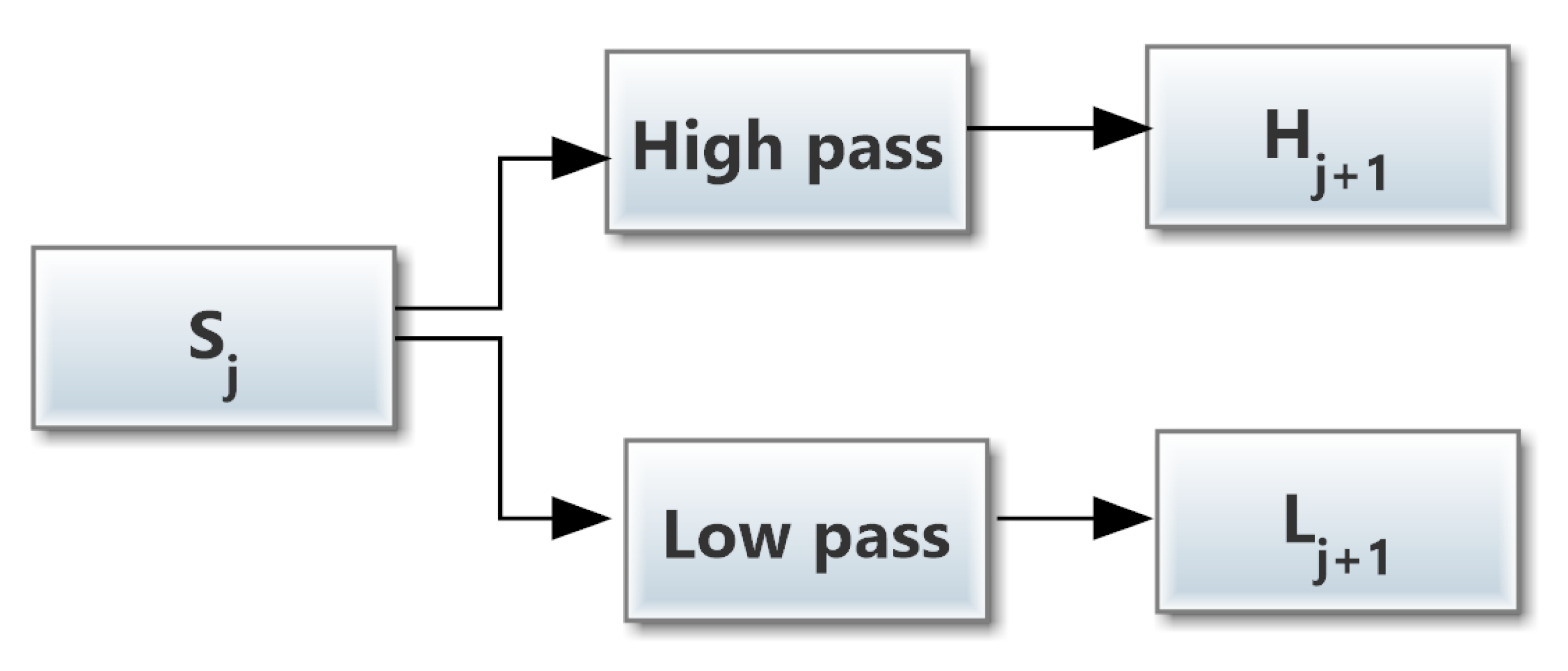
The NDWT is an un-decimated form of a conventional DWT based on Mallat’s multiresolution algorithm [37]. It is performed by insertion of zeros in the filter for up-sampling and suppressing the down-sampling step of the decimation algorithm (Figure 2). Its main advantage is translation-invariance with respect to the DWT. Therefore, the main signal is not decimated, so the resolution can be maintained, also the signal-to-noise ratio has increased [38]. It makes this algorithm suitable for structural damage detection, signal fusion, and feature extraction.
The NDWT decomposition uses the scaling function (low-pass filter) and the wavelet function (high-pass filter) [39]. These functions satisfy the following two-scale relation:
where and are the impulse responses of low-pass and high-pass mirror filters. The jth level of decomposition is shown in Figure 2.The decomposition formulas of NDWT are as follows:
where and are the low-frequency and high-frequency components of the NDWT, respectively. and are upsampled by when the jth level is processed, which results in a constant length of and . The approximations are the high-scale, low-frequency components of the signal. The details are the low-scale, high-frequency components of a signal. Since the wavelet transform analysis can effectively differentiate the wave components with different frequencies and facilitate the formulation of the damage quantification index, the basic procedure of the wavelet transform-based energy can be calculated as
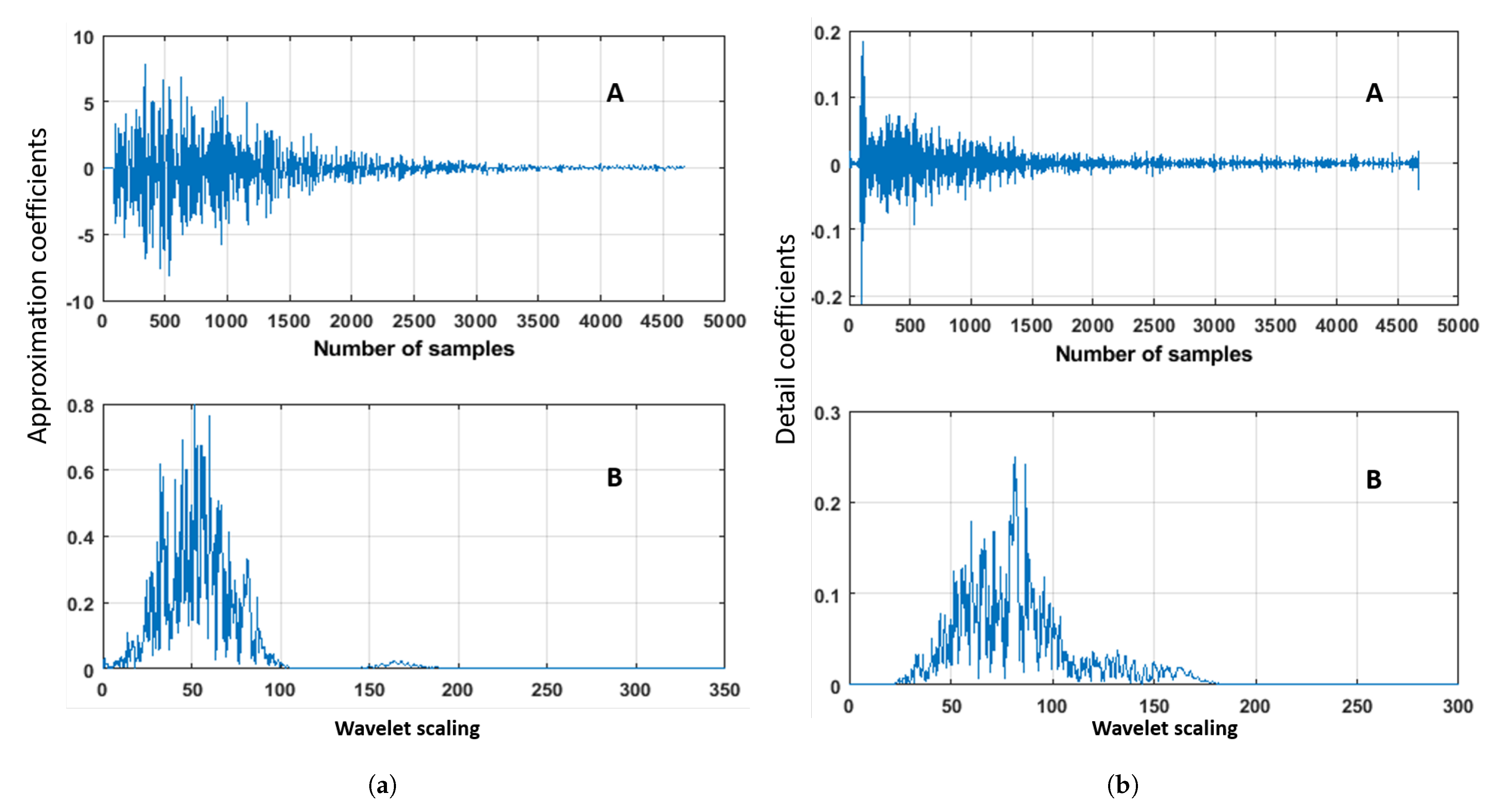
where represents the energy of each set of approximation coefficients, and represents the energy of the initial (baseline signal) set of such coefficients. With this implementation, an coefficient index can be formulated to characterize the energy variation of the low- and high-frequency components. The low and high scaling wavelet decomposition of an exemplary ultrasonic signal is shown in Figure 3.
2.3. Continuous Wavelet Transform
CWT is an effective signal processing approach, used to detect changes/cracks in many applications due to the very high sensitivity to even tiny disturbances in a time-domain signal. The CWT algorithm is described by the following integral equation:
where j is the scaling coefficient, is translational value, and is the mother wavelet with respect to the measured signal. It can extract features that can be related to changes/damage in the structure. CWT is an estimator used to quantify the energy diffusion value from the acquired signal. The CWT is applied to develop a time-frequency scalogram (It is a combination of low and high coefficients matrix that illustrates signal energy) of a signal showing proper time and frequency localization. CWT analysis is effective due to its capability to analyze the non-stationary signals at different frequencies simultaneously [24]. In each signal subset can be written as
where is each block of CWT definition computed from . A CWT-based change matrix is developed to evaluate the changes in the structure and crack propagation. The features can be extracted using the CWT coefficient, which are related to changes/damage in the structure. CWT coefficient is computed from Equation (15).
where the matrix element represents the CWT-based index of changes associated with the time histories of each pair of the sensors. represents the CWT coefficient based on initial signal (baseline), and represents CWT coefficient based on measured signal with time histories, where i and j are the indices of CWT matrix. Bump wavelet is used as a mother wavelet in this study due to the sensitivity of diffuse signals.
3. Experimental Objects
To validate our methodology, two different structures were considered according to the previous description. From the literature, it was found that some of the signal processing methods are not well suited in real structures due to different influences in the structures. Therefore, we have considered two structures. First, the benchmark RC structure was used to test the sensitivity of the extracted features from embedded ultrasonic sensors during a four-point bending test in the lab. The second structure on which the extracted feature was tested was a reference RC structure called a BLEIB structure. The goal of the experiment was to detect cracks in concrete during quasi-static loading in the field conditions using features based on the energy of wavelet coefficients extracted from raw ultrasonic signals.
3.1. Benchmark RC Structure
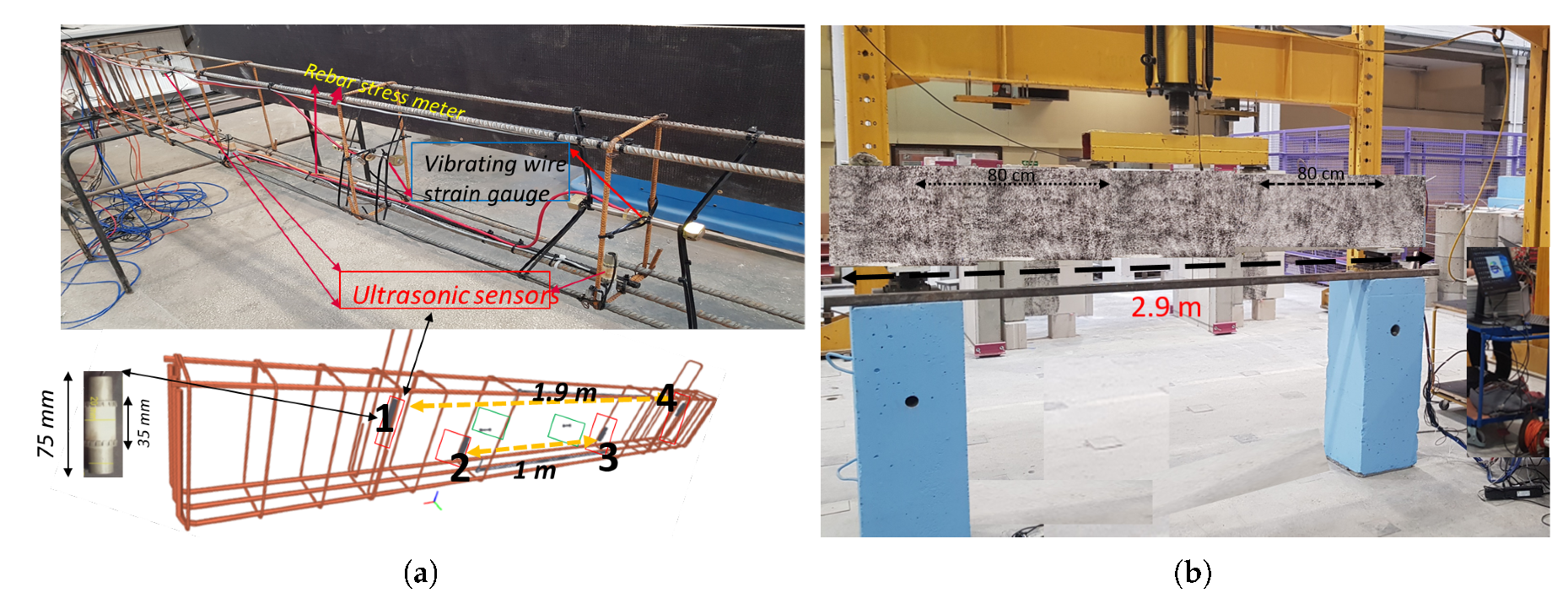
The four-point bending test was performed on a three meter size (2.9 m × 0.2 m × 0.4 m) reinforced concrete beam. The beam was reinforced with two 10 mm diameter rebars in the tension zone and three 14 mm diameter rebars in the compression zone, attached by thirteen 6 mm diameter stirrups (see Figure 4). The beam was made of concrete class C25/30 with compressive strength Fcd = 27.57 MPa.
During casting, four ultrasonic sensors and two vibrating wire strain gauges were embedded inside the beam in such a way that one can follow the changes in concrete [40]. The location of the sensors can be seen in Figure 4a. The number and position of ultrasonic sensors also can be seen in Figure 4a. The curing period was 28 days at a temperature of ± 2°. The LVDT was placed vertically in the middle of the beam to measure the deflection of the beam during the four-point bending test.
3.2. Reference Real Structure
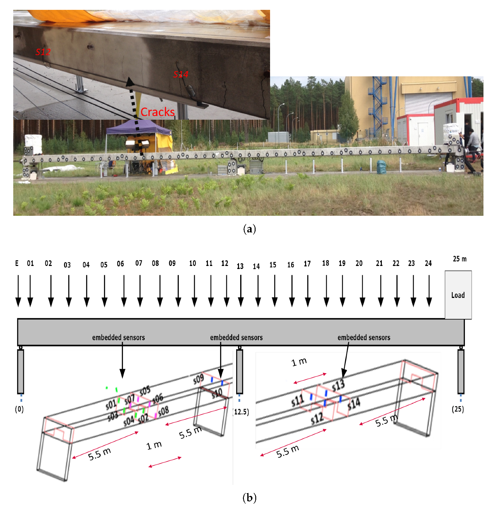
As mentioned in the introduction, bridges have a key economic factor in the infrastructure system. Therefore, its degradation or collapse can bring significant impact (life safety, financial and traffic system) on our society. In view of the above, BAM developed a reference real structure shown in Figure 5 called BLEIB structure (shared object for INFRASTAR project) at Horstwalde (Berlin, Germany) to perform different experiments on this object [41].
It is a 25 m long reference structure, which consists of three supports: one in the middle and two on the edges of both sides and had five cross-sections. The load cell was installed on the front bridge side (fixed anchor) on the tendons during their initial installation to control the post-tensioning parameters of the structure. There were fourteen ultrasonic sensors installed during preparation of this structure in 2017. The sensors are embedded in different cross-sections of the beam. The position of the sensors and their distances from each other are presented in Figure 5b.
4. Experimental Programs and Results
4.1. Benchmark RC Structure
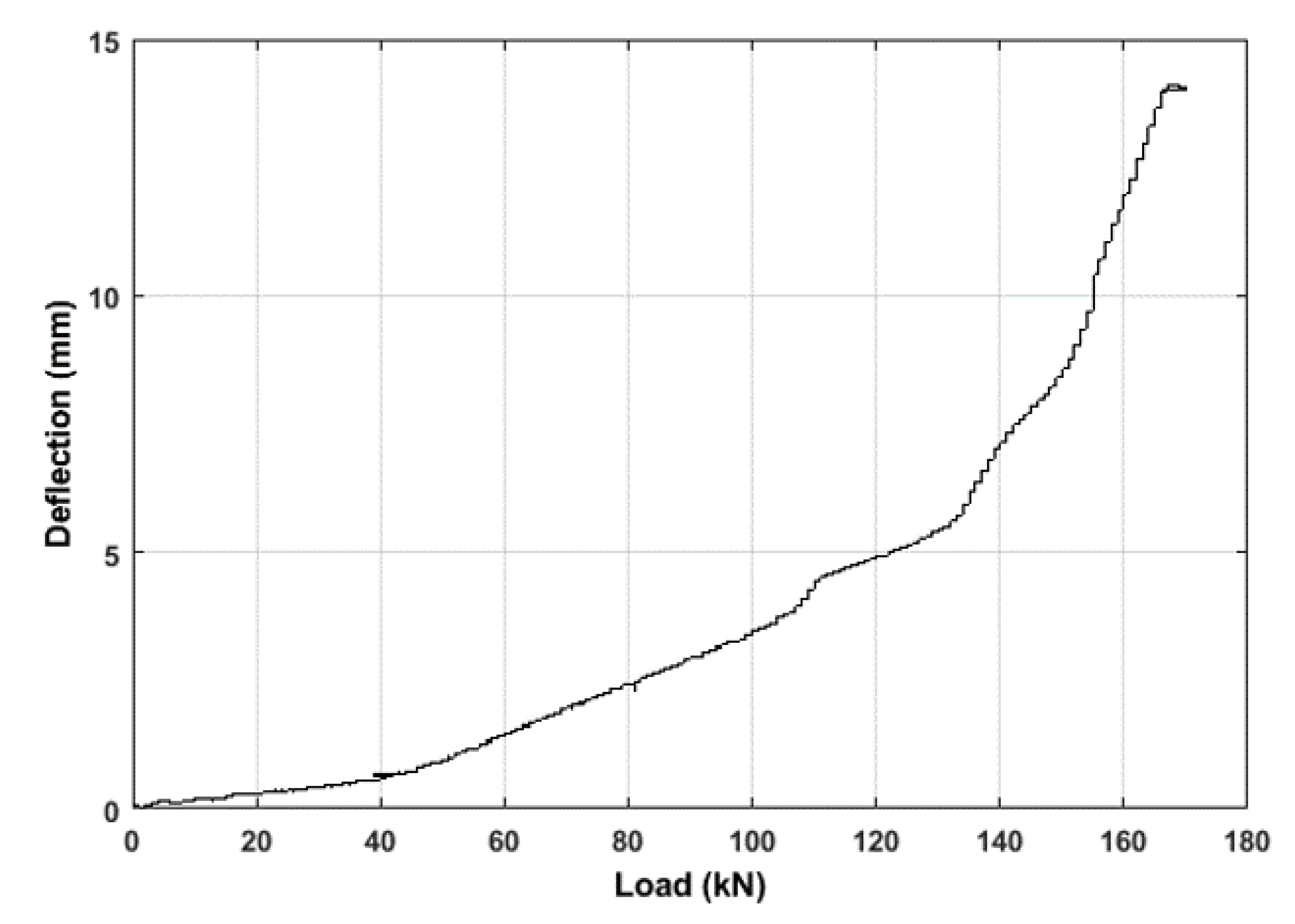
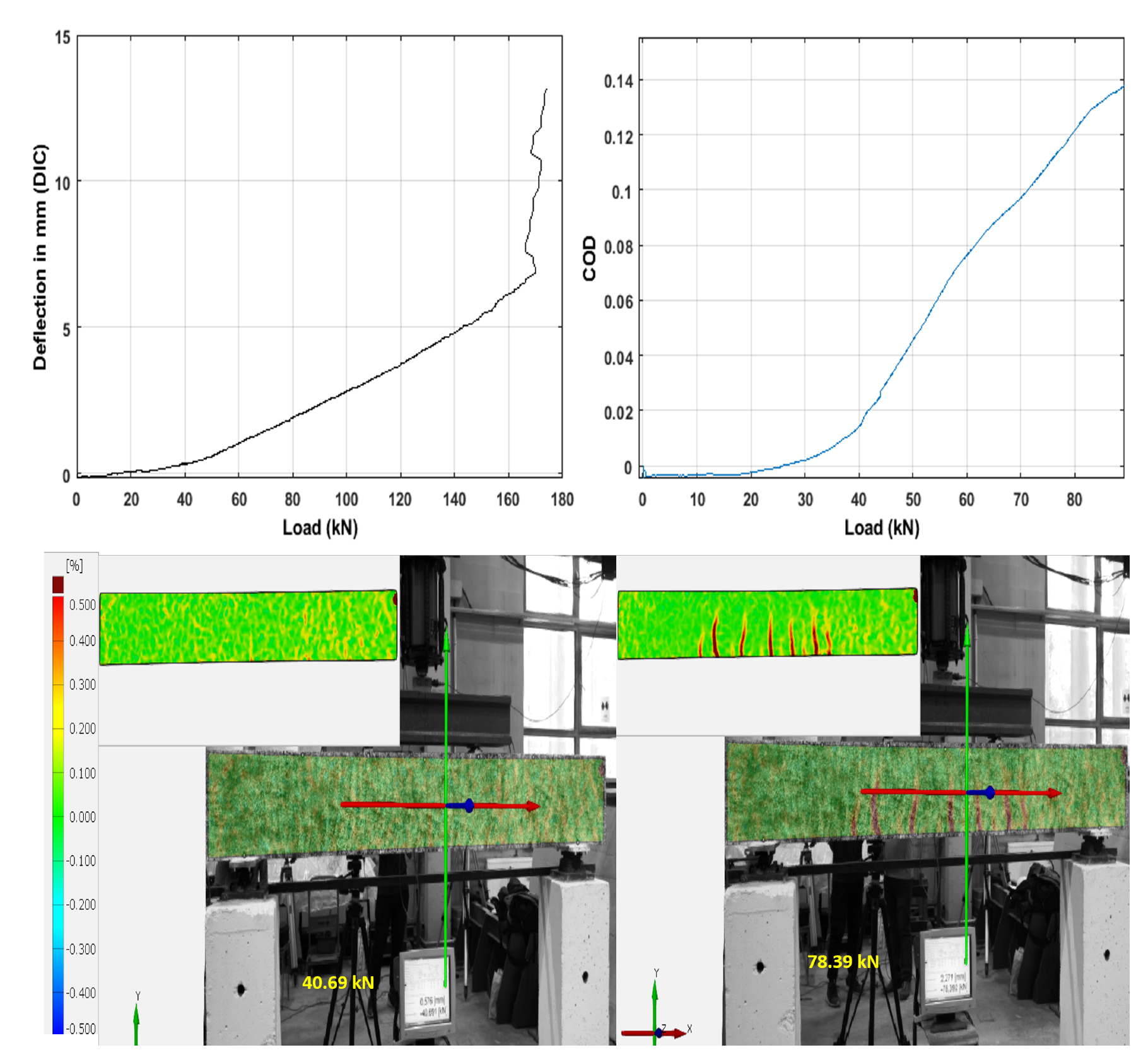
During the four-point bending test, the loading procedure was performed in a continuous manner; the loading step was approximately 1 kN for each minute until 120 kN, then it was increased by 5 kN for each minute. The deflection of the beam can be seen in Figure 6. One can see that the deflection of the beam lost linearity around 42 kN due to crack formation. The crack opening and propagation can also be observed from the DIC measurements (see Figure 7). The middle deflection and crack opening displacement (COD) was also analyzed through DIC measurements. The displacement fields were used to determine the COD value. The discontinuity of two points in the middle of the beam by following the crack path was used to calculate COD values, the transform of the dissipated energy, and the crack opening along the crack path was measured (anticipating the crack opening width vs. depth line to zero). The COD values were considered until 90 kN, as all the cracks appeared during this loading period. It is also visible from the surface image that at 40 kN the first crack appeared, and all the cracks formed during 80 kN.
The new data acquisition system was used to acquire ultrasonic signals during the loading program (more details about the data acquisition system can be found in [42]). The simple block diagram is shown in Figure 8. An NI DAQ card generated the pulse signal to excite the ultrasonic transmission sensor. On the other hand, a pre-amplifier was used to record the good quality of signals. The data acquisition system recorded eight measurements (ultrasonic signals) in each minute.
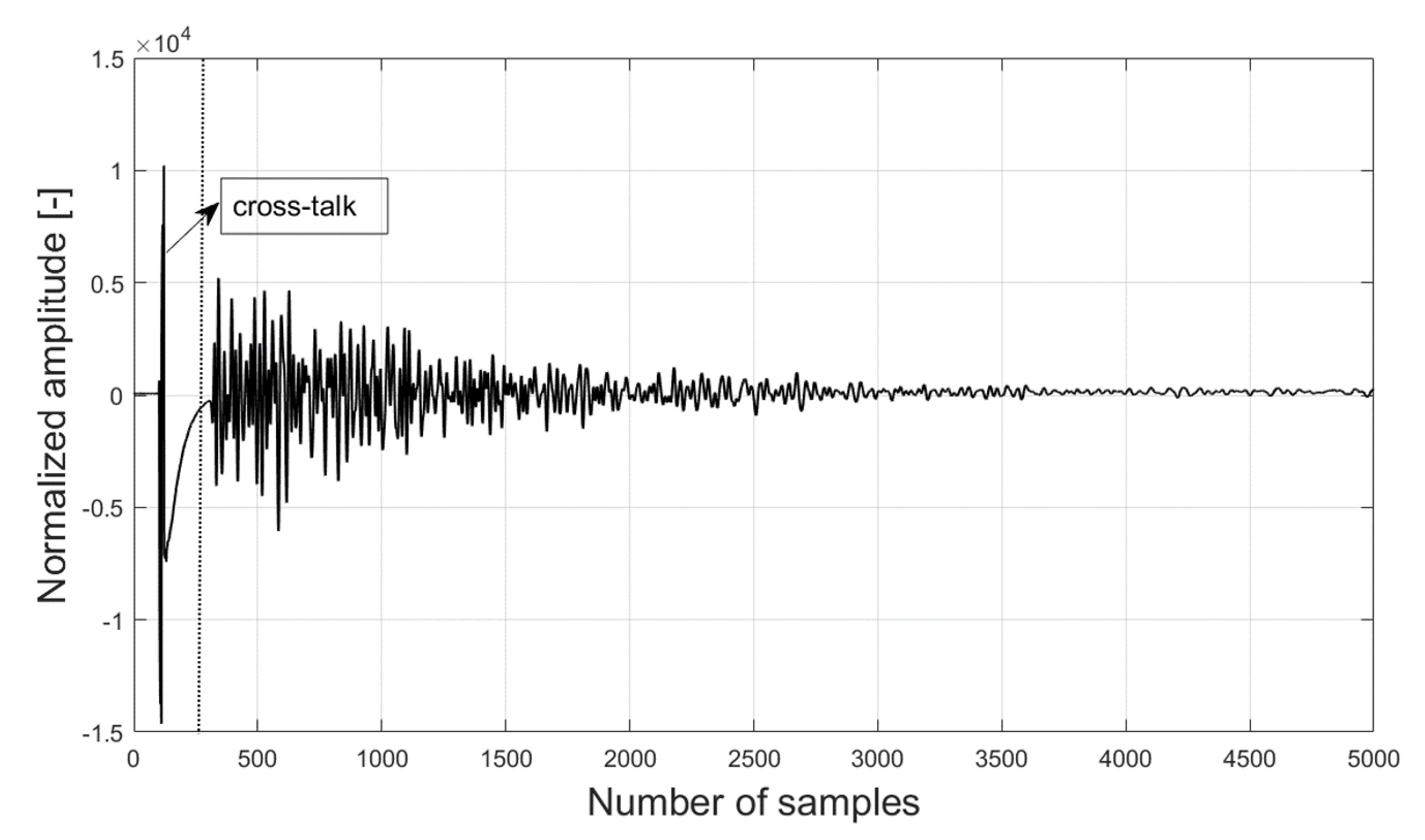
The ultrasonic wave, which has a center frequency of 62 kHz and traveled through the concrete beam, was recorded by other sensors that were considered as a single measurement. Figure 9 shows an acquired ultrasonic signal recorded by the sensor combination S01R04 as an example. The acquired raw signals were processed during the post-processing period. The cross-talk portion was removed during post-processing. To extract meaningful features from the acquired raw signals, the algorithms based on the wavelet transform described in Section 2 were used. The diffuse ultrasonic wave is a non-stationary waveform due to reflection and diffraction coming from concrete material since the wavelength of the discontinuities can be higher than that of the micro cracks. Therefore, wave scattering at the concrete material is more likely to affect the high-frequency components in the acquired ultrasonic signals. Hence, it is more meaningful to analyze low-frequency wavelet transform energy that can relate to micro-cracks.The low and high scaling wavelet decomposition are shown in Figure 3. One can see from Figure 3a that the highest peak was around 60 kHz, which relates to the center frequency of the sensor. On the other hand, Figure 3b shows the highest peak was around 80 kHz that mainly comes from the scattering part from the signal. Therefore, this low wavelet scaling can be less meaningful.
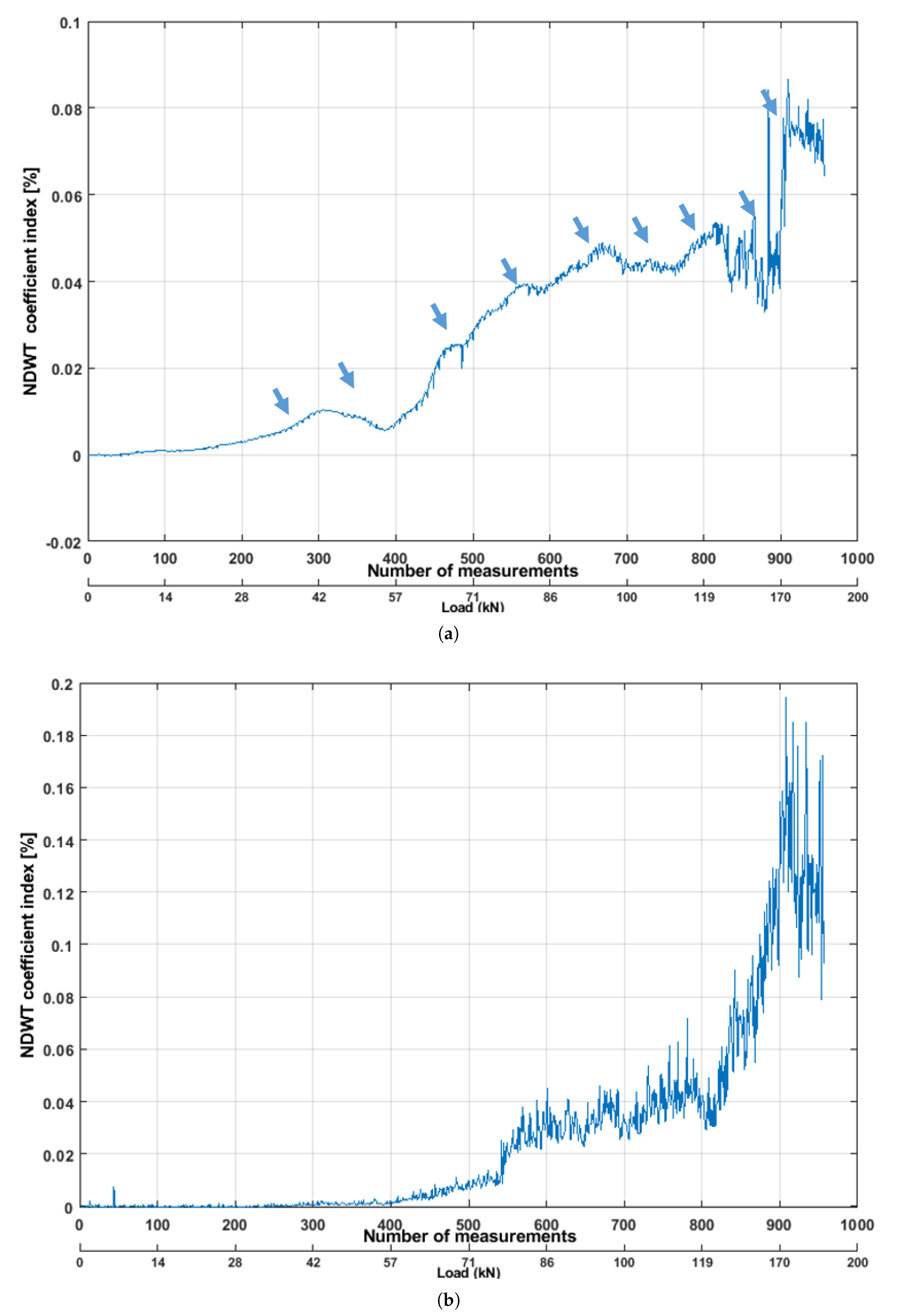
In this study, two pairs of sensors located on the top and bottom of the beam were analyzed. First, NDWT was applied to the raw ultrasonic signal time histories, acquired from the top pair of the sensors. The NDWT coefficient was increased (high scaling) during the initial phase of the loading. The coefficient was started to decrease after 42 kN. It should be noticed that the cracks started forming in that period. When the crack started forming, the low-frequency components of the waves propagated with attenuation, and high-frequency components were scattered. It can be observable in Figure 10b. The observed values (coefficients) lost linearity after around 68 kN, when most of the cracks were formed and started to propagate. Also, the value of coefficients was not linearly increased comparing with the continuous loading period. Therefore, this low wavelet scaling part of the result can be avoidable. The authors [28,43] also used a band pass filter to remove the high-frequency component from the diffuse ultrasonic signals. However, one can see in Figure 10a that the NDWT coefficient started to lose its linearity after 42 kN, which indicates the cracks forming and propagation (marked with the blue arrow). From the literature, the simulation of ultrasonic surface wave indicates similar results [14]. This pair of sensors was located on the top portion of the beam. Therefore, these results were not surprising. The cracks were formed first on the bottom side of the beam; therefore, the influence of the signals was lower.
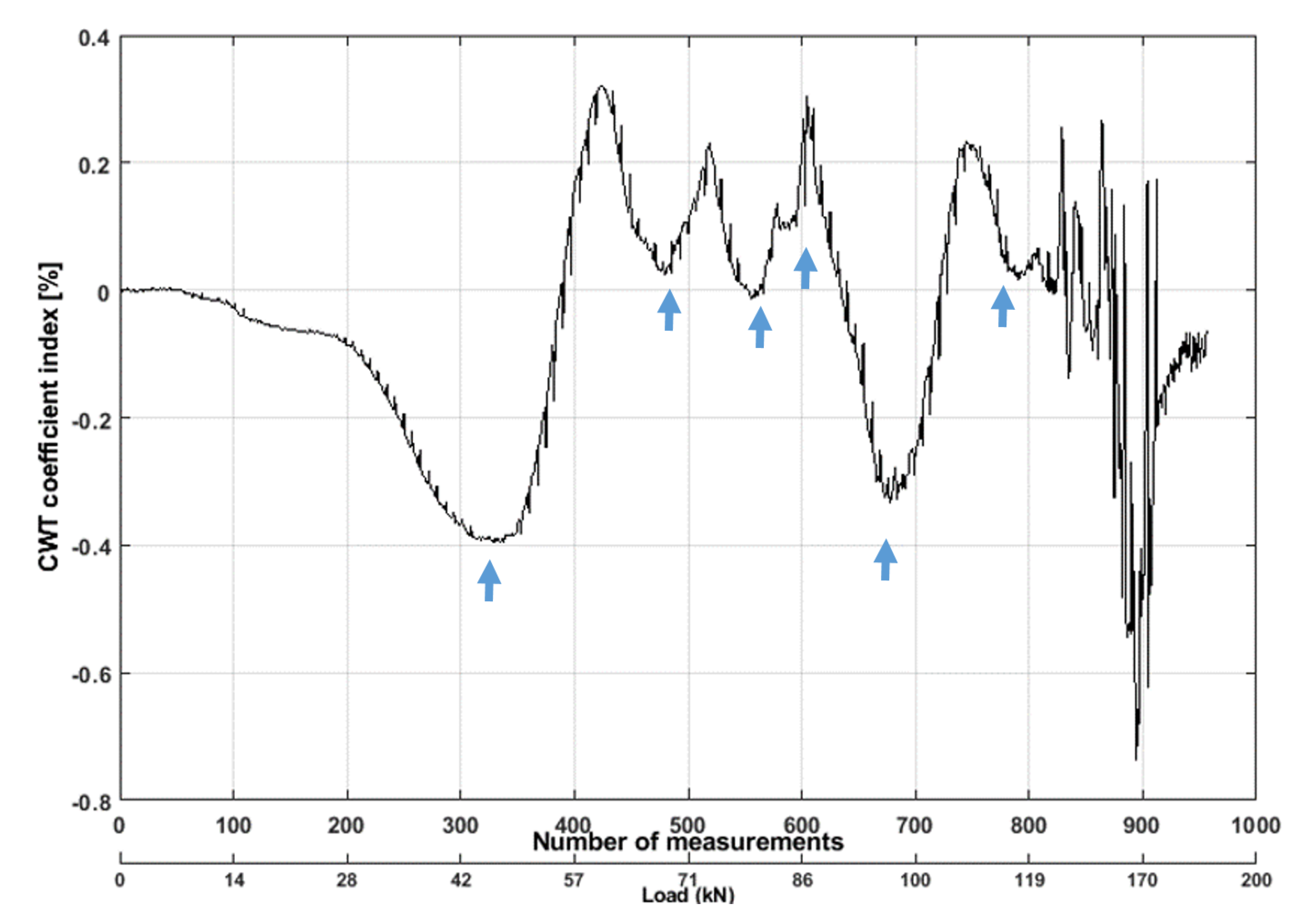
Similar phenomena can be observed in Figure 11. The CWT coefficient started to change due to the compression phase of the beam until 42 kN. After that, it started to change its phase, which means the difference of the wave packets (scalogram coefficient) was higher, indicating that the signal amplitudes started to decrease due to micro-cracks appearance. The coefficients fluctuated after 57 kN, which indicated the amplitude and phase of the signals were changing rapidly. When multiple cracks were formed and propagated to the direct path of the sensors, then cracks started to intercept the signal, which delayed the first arrival of the signal and decreased the amplitude.
The NDWT coefficient extracted from the bottom pair of sensors can be seen from Figure 12a. The coefficient increased slowly until 33 kN. Then, a sudden decrease can be observed due to forming microcracks. Due to the influence of micro-cracks, the approximation coefficients of signals first caused a noticeable decrease after 42 kN. One should remember this was the period when most of the cracks started to form. The changes of this coefficient were linear after 50 kN. However, several non-linearities can be observed when the new cracks started to form. There were no noticeable changes observable from the detailed coefficients resulting from NDWT. This is due to the sensor locations in the beam, as all the micro-cracks formed on the bottom of the beam.
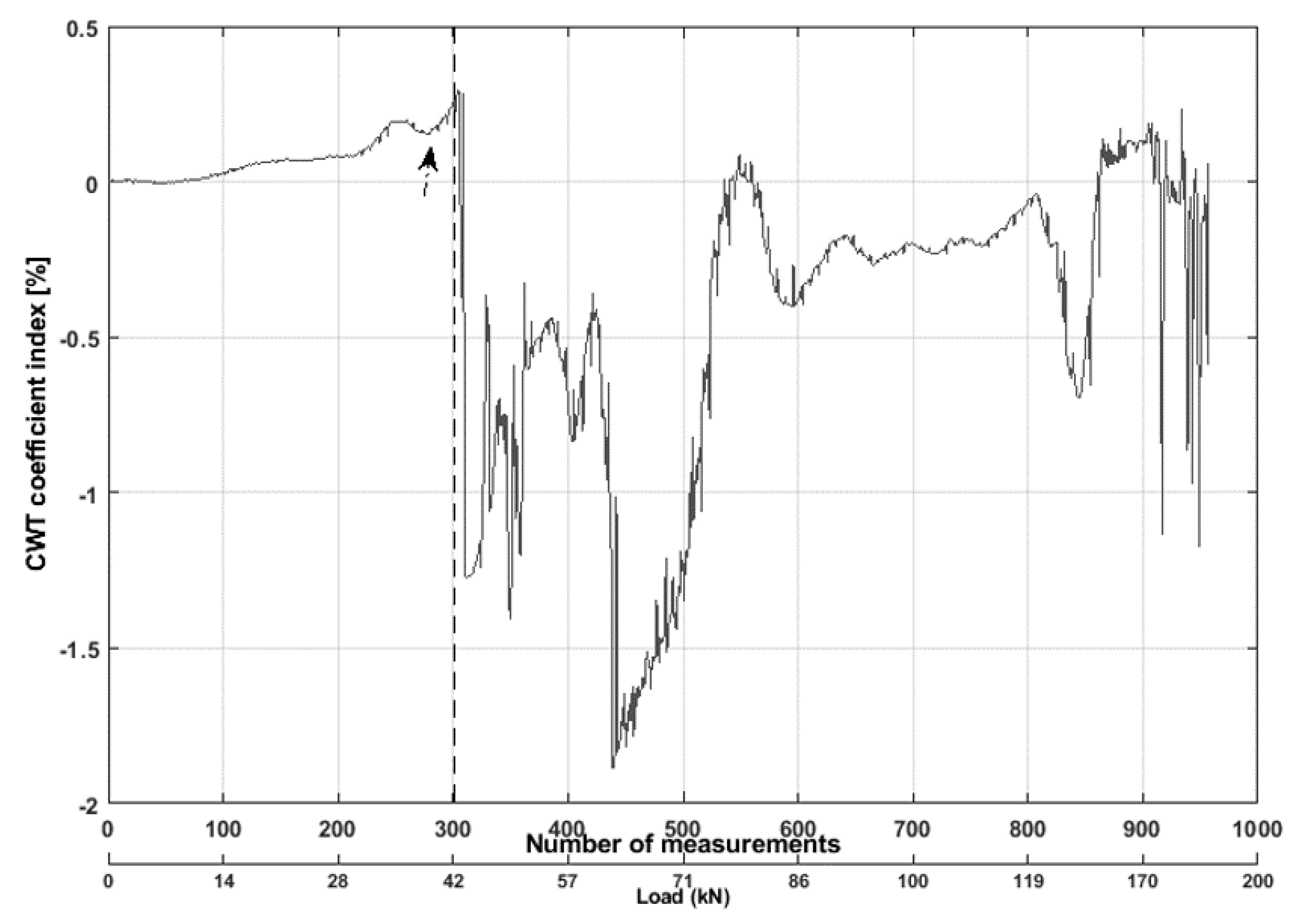
The CWT coefficient was also influenced when the micro-cracks formed (see Figure 13). The CWT coefficient dropped 1.2% at 42 kN. Further, the tension and compression zone can be observed from CWT coefficients. Therefore, both the ultrasonic features and results from other techniques indicated similar results. However, the ultrasonic features indicated non-linearity in their coefficient values before forming micro-cracks, which was not noticeable on other techniques. The results were comparable with similar studies [43,44].
4.2. Reference Real Structure
The quasi-static load test was performed in a real RC structure described in Section 3.2 to detect changes in the reference real structure. Several control cracks were created in one of the beams in this structure (see Figure 5a). The cracks were located between sensor numbers 12–14. The cracks were created after the manufacturing of this beam. The post-tensioning load was reduced, and a certain amount of load was placed in that position of the structure to create those cracks during the initial phase of the structure. After that, the beam was reloaded with 605 kN, so all the cracks were closed during our test. The test was performed on a rainy day. Therefore, external factors such as wind and changing temperature could impact the structure which ultimately included recorded signals The same data acquisition system mentioned in Section 4.1 was used to acquire the ultrasonic signals during the test.
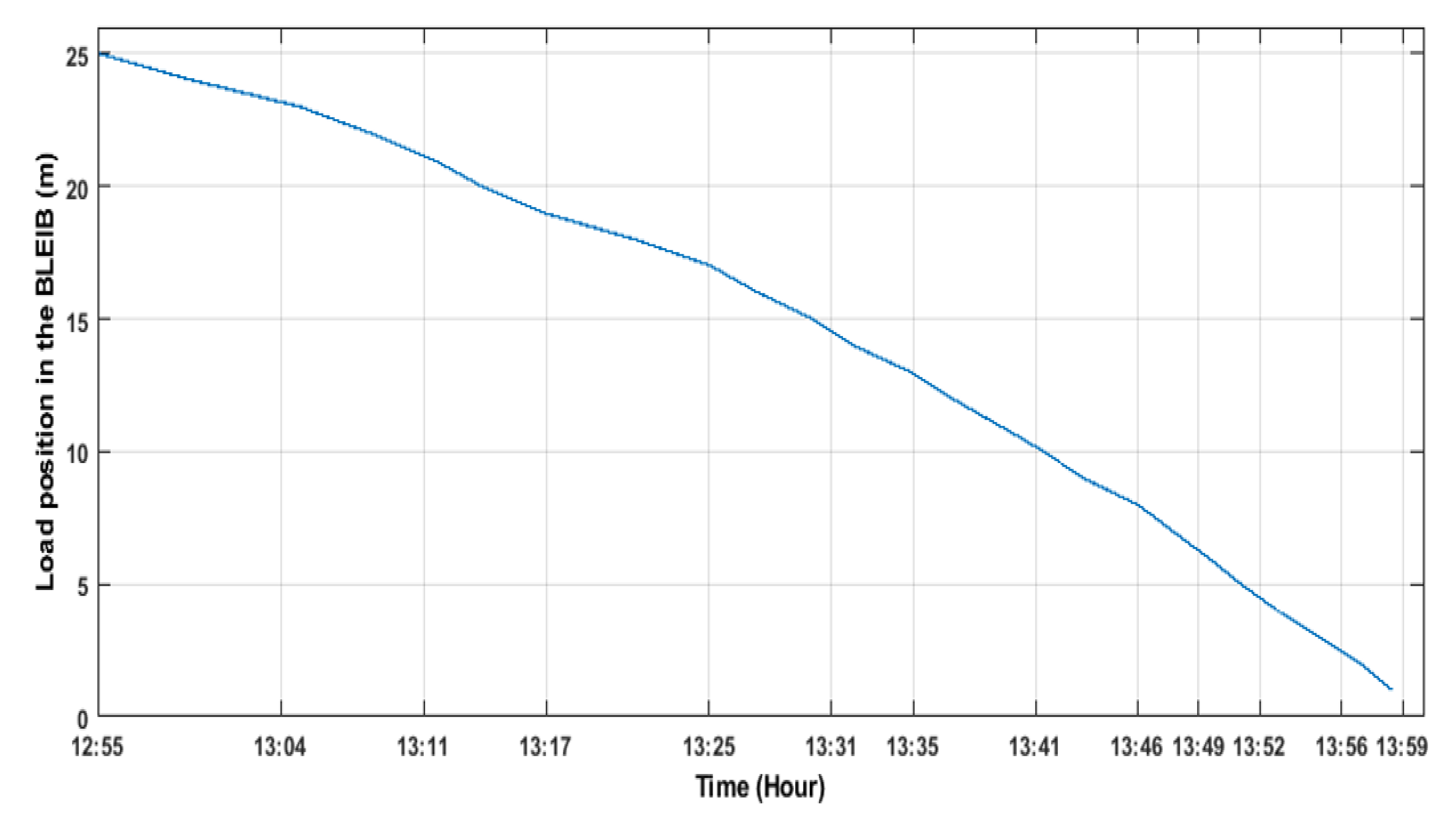
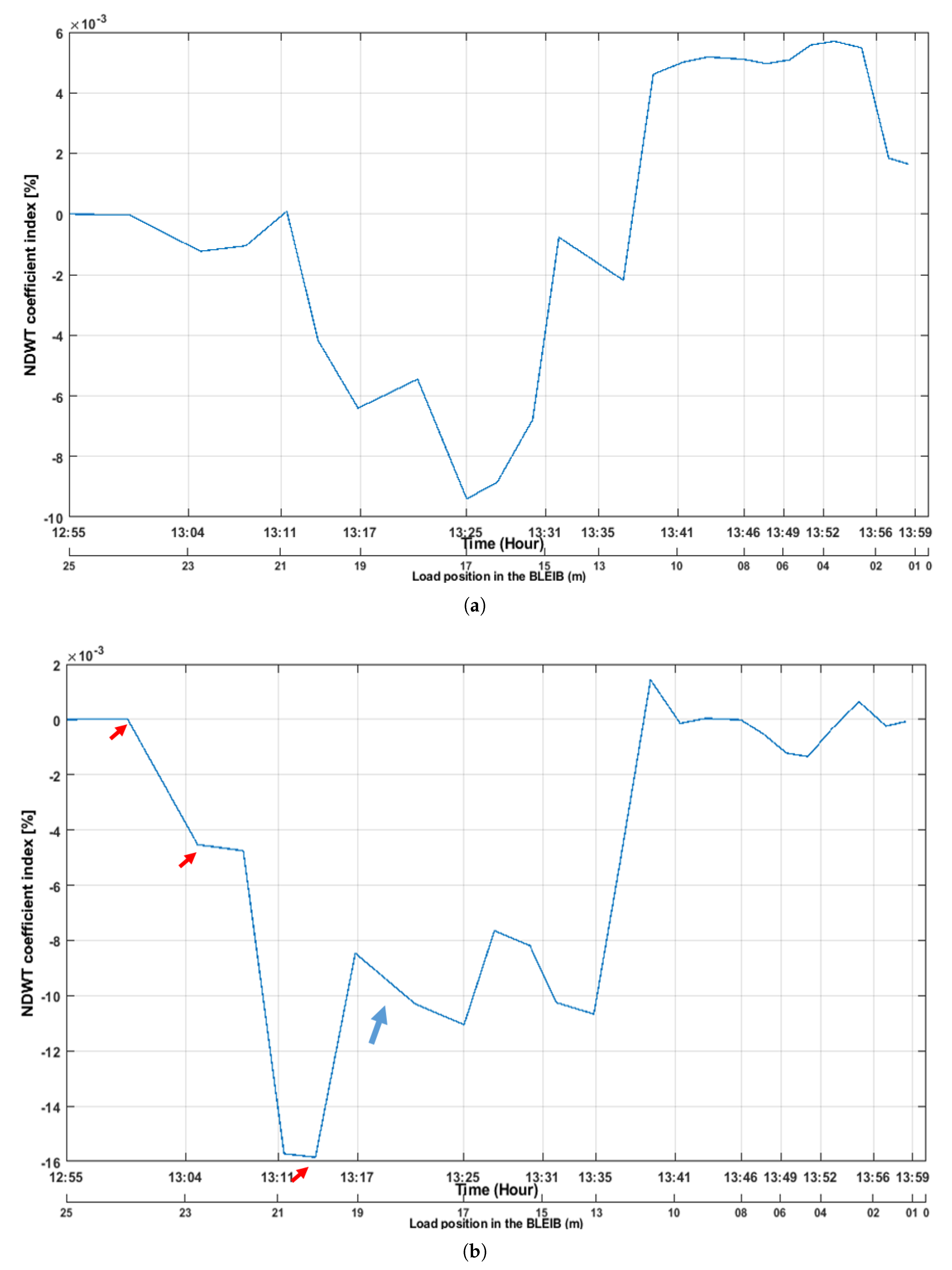
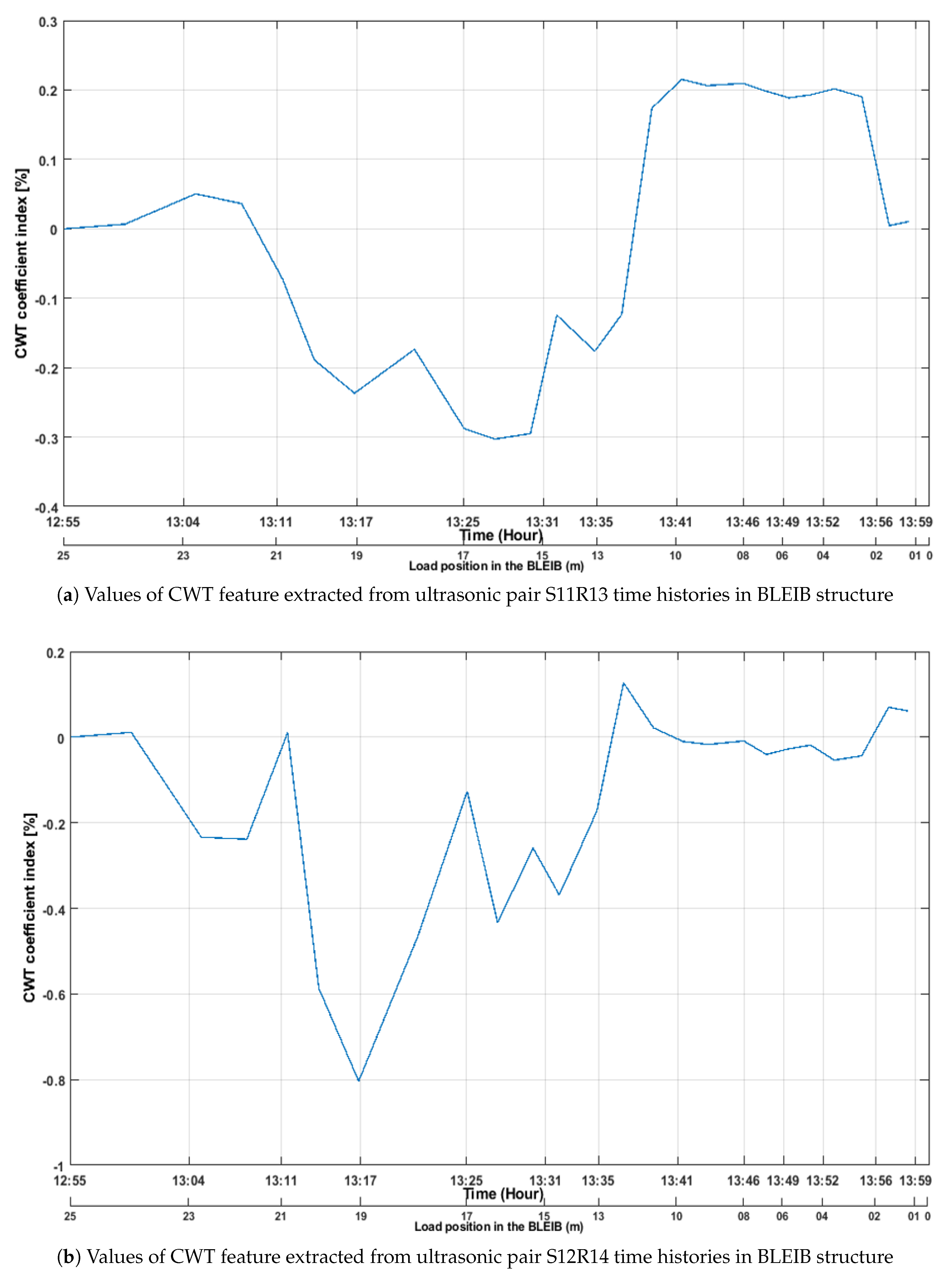
During this experiment, one ultrasonic measurement signal was acquired in each minute. During the test phase, the quasi-static load was moved step-wise, and it started from the edge of the structure (see Figure 5b). Each step and time were noted down on paper during the test (see Figure 14). The load was placed on each meter of the structure and held for one minute in each position, then placed to the next position. The main reason for this test was to validate the sensitivity of the embedded sensors by detecting the known cracks in this structure. The ultrasonic signals were acquired from all pairs of the sensors in this structure. The goal of this study was to detect cracks in this reference structure (which can be comparable to a real structure) using presented advanced signal processing methods as a feature. As the location of the cracks were known, two pairs of sensors were considered for this study. The acquired signals from sensor pair S12R14 and S11R13 were analyzed during the post-processing period. The wavelet transform was applied to acquired signals from both pairs of sensors. The NDWT coefficient extracted from sensors pair S11R13 can be seen from Figure 15a. The coefficient started to change when the load was moved from the edge of the structure. The coefficient was close to zero when the load moved to 21 m in the beam, as this was the starting position of the cracks. The sensors were embedded in the top portion of the beam. Therefore, there could be some influences in the signal, as we are considering a diffuse ultrasonic signal that is coming from different parts of the structure. The coefficient increased when the load was placed in different locations of the structure. Each step was clearly observable from the NDWT feature. When the load comes to the different cross-sections (S04–S10), the coefficient also changed, but in this time changes were small. This is due to the distance from the load to the measuring pair of sensors. The CWT coefficient value also changed in a similar manner to the NDWT coefficient (see Figure 16a). The CWT coefficient increased when the load was placed approximately 17 m from the edge of the beam, where the sensors numbers 11 and 12 were located. Therefore, it can be observed that the coefficient increased when the load was situated on top of the ultrasonic transmitter. This is obvious, as the sensors transmit the ultrasonic signal, and the amplitude of the signal changed due to direct influences from the load.
The NDWT coefficient for S12R14 (S12 transmit ultrasonic signal and R14 receive the diffuse signal) can be seen in Figure 15b. The coefficient changed during each loading step in the structure. The coefficients were steady for some period on each loading step (marked with the red arrow in the Figure 15b), and, the result was as expected, as the quasi-static load stayed for 1 min on each position in the beam. The NDWT coefficient increased its highest values after the load was placed at 21 m of the structure. Then, it suddenly dropped to 0.008%, when the load was placed at 19 m of the beam. It is remarkable, as the load was placed in the crack position during this period. The cracks were between sensor numbers S12–S14 in the same beam. This indicated that the coefficients’ sudden decrease was due to cracks openings. As the cracks opening influence the low-frequency component of the signals. The coefficient values stopped increasing due to cracks opening in the structure, and after the load moved to sensor number S12 (which was transmitting the ultrasonic signals), the influences in the signals became less. The NDWT coefficient was sensitive to detect the load, even during the initial phase of the loading when the load moved at 21 m in the structure. The CWT coefficient values increased when the load firstly moved and was placed 1 m from the edge of the structure. Then, the coefficient suddenly started to drop when the load moved to 18 m of the structure where the cracks were located. The changes in CWT coefficient were again recognizable when the load was placed at different cross-section (where sensors 01–08 were situated), but the influence was less as the load was far from the measuring sensors. However, both coefficients can detect the cracks, load and each step of the load in the structure.
5. Conclusions
This paper presents a damage detection of multiple RC structures based on wavelet transform and embedded ultrasonic sensors. A test procedure to initiate cracks and evaluate the health status of the RC structures under increased loading and quasi-static loading in the presence of environmental changes has been proposed. The detection of cracks in laboratory environments can be seen in much literature; however, less studies can be found that were conducted outside of the laboratory environment. Therefore, it is difficult to use a simple signal processing algorithm to extract meaningful features from the raw ultrasonic signals, especially for real structures due environmental influences to the structure. Although, different signal processing methods can be applied to the raw signals. However, it will not lead to a good result or high efficiency. The extracted features from the raw signals by using wavelet transform is a base for transferring SHM methods from the laboratory environment to the real structure.
The results have shown that the applied wavelet transform to extract features was sensitive to detect loads, cracks, and positions of the load in the structure. A large portion of the structure can be monitored using a limited number of ultrasonic sensors. The results showed high sensitivity to detect crack opening. However, the NDWT coefficient was sensitive to the micro cracks, loads, and even when the load stayed for minutes on the structure. The high-frequency component can be avoided using NDWT; therefore, the results were steady. The results have shown that the applied wavelet transform was sensitive to detect cracks under the influence of environmental changes even without using the extra filter to remove noises. Therefore, the applied methods will be beneficial for ultrasonic-based SHM that will allow avoiding using an extra filter for removing noises. The CWT coefficient was sensitive to cracks, which also indicated us to consider a feature-based fusion method to improve the damage detection capability. Therefore, this part of our work is in progress. The comparison of using different digital filters will be investigated. The work will also be further investigated in long-term monitoring to detect the health status of the real bridge.
Author Contributions
All the authors conceived and designed the experiments; J.C. performed NDT experiments, performing the ultrasonic measurements, signal analysis, algorithms and correlation studies, and prepared the full version of the manuscript; X.W. participated in preparation of test specimens, performing the ultrasonic measurements and improving the manuscript by comments; M.S. also participated in preparation of test specimens, suggested the composition of this paper, and supervised the overall process. All authors have read and agreed to the published version of the manuscript.
Funding
Open Access funding is enabled by vouchers of MDPI. This research work was performed within the European project INFRASTAR, Innovation and Networking for Fatigue and Reliability Analysis of Structures-Training for Assessment of Risk (https://infrastar.eu), which has received funding from the European Union’s Horizon 2020 research and innovation program under the MarieSkłodowska-Curie Grant No. 676139.
Institutional Review Board Statement
Not applicable.
Informed Consent Statement
Not applicable.
Data Availability Statement
Not applicable.
Acknowledgments
The authors wish to acknowledge the help of Ernst Niederleithinger, BAM, for the sensors, data acquisition setup, and Tomasz Hahn from the Silesian University of Technology and colleagues from the NeoStrain Sp. z o.o., respectively, for helping with the data acquisition setup and experiment in the lab. We thank Andrzej Katunin for his technical suggestion and also the four “anonymous” reviewers for their comments which helped to improve the manuscript.
Conflicts of Interest
The authors declare no conflict of interest.
Abbreviations
The following abbreviations are used in this manuscript:
| RC | Reinforced concrete |
| BAM | Bundesanstalt für Materialforschung und -prüfung |
| NDT | Non-Destructive Testing |
| CWI | Coda wave interferometry |
| AR | Autoregressive model |
| CC | correlation coefficient |
| NDWT | Non-Decimated Wavelet Transform |
| CWT | Continuous wavelet transform |
| FFT | Fast Fourier transform |
| STFT | Short-time Fourier transform |
| UPV | Ultrasonic pulse velocity |
| AE | Acoustic emission |
| DIC | Digital image correlation and tracking |
| LVDT | Linear variable differential transducer |
References
- Chakraborty, J.; Katunin, A.; Klikowicz, P.; Salamak, M. Embedded ultrasonic transmission sensors and signal processing techniques for structural change detection in the Gliwice bridge. Procedia Struct. Integr. 2019, 17, 387–394. [Google Scholar] [CrossRef]
- Scott, M.; Rezaizadeh, A.; Delahaza, A.; Santos, C.G.; Moore, M.; Graybeal, B.; Washer, G. A comparison of nondestructive evaluation methods for bridge deck assessment. NDT E Int. 2003, 36, 245–255. [Google Scholar] [CrossRef]
- Hussain, A.; Akhtar, S. Review of Non-Destructive Tests for Evaluation of Historic Masonry and Concrete Structures. Arab. J. Sci. Eng. 2017, 42, 925–940. [Google Scholar] [CrossRef]
- Lu, Y.; Michaels, J.E. A methodology for structural health monitoring with diffuse ultrasonic waves in the presence of temperature variations. Ultrasonics 2005, 43, 717–731. [Google Scholar] [CrossRef]
- Sikorski, W. Acoustic Emission—Research and Applications; InTech: London, UK, 2013. [Google Scholar]
- Eid, R.; Muravin, B.; Kovler, K. Acoustic Emission Monitoring of High-Strength Concrete Columns Subjected to Compressive Axial Loading. Materials 2020, 13, 3114. [Google Scholar] [CrossRef]
- Hong, S.; Yoon, S.; Kim, J.; Lee, C.; Kim, S.; Lee, Y. Evaluation of Condition of Concrete Structures Using Ultrasonic Pulse Velocity Method. Appl. Sci. 2007, 10, 706. [Google Scholar] [CrossRef] [Green Version]
- Ivanchev, I.; Slavchev, V. About the Possible Limitations in the Usage of the Non-Destructive Ultrasonic Pulse Velocity Method for Assessment of Cracks in Reinforced Concrete Structures, Subjected to Direct Environmental Exposure. Buildings 2019, 9, 202. [Google Scholar] [CrossRef] [Green Version]
- Niederleithinger, E.; Wolf, J.; Mielentz, F.; Wiggenhauser, H.; Pirskawetz, S. Embedded Ultrasonic Transducers for Active and Passive Concrete Monitoring. Sensors 2015, 15, 9756–9772. [Google Scholar] [CrossRef] [PubMed] [Green Version]
- Anugonda, P.; Wiehn, J.S.; Turner, J.A. Diffusion of ultrasound in concrete. Ultrasonics 2001, 39, 429–435. [Google Scholar] [CrossRef]
- Lu, Y.; Michaels, J. Feature Extraction and Sensor Fusion for Ultrasonic Structural Health Monitoring Under Changing Environmental Conditions. IEEE Sens. J. 2009, 9, 1462–1471. [Google Scholar]
- Rucka, M.; Wilde, K. Experimental Study on Ultrasonic Monitoring of Splitting Failure in Reinforced Concrete. J. Nondestruct. Eval. 2013, 32, 372–383. [Google Scholar] [CrossRef] [Green Version]
- Fröjd, P.; Ulriksen, P. Frequency selection for coda wave interferometry in concrete structures. Ultrasonics 2017, 80, 1–8. [Google Scholar] [CrossRef] [PubMed]
- Wang, Z.; Wei, L.; Cao, M. Damage Quantification with Embedded Piezoelectric Aggregates Based on Wavelet Packet Energy Analysis. Sensors 2019, 19, 425. [Google Scholar] [CrossRef] [Green Version]
- Liu, A.; Wang, L.; Bornn, L.; Farrar, C. Robust structural health monitoring under environmental and operational uncertainty with switching state-space autoregressive models. Struct. Health Monit. 2018, 18, 435–453. [Google Scholar] [CrossRef]
- Clement, A.; Laurens, S. Vibration-based damage detection in a concrete beam under temperature variations using AR models and state-space approaches. J. Phys. 2011, 305, 012040. [Google Scholar] [CrossRef]
- Li, M.; Ren, W.X.; Huang, T.L.; Wang, N.B. Experimental investigations on the cross-correlation function amplitude vector of the dynamic strain under varying environmental temperature for structural damage detection. J. Low Freq. Noise Vib. Act. Control 2018. [Google Scholar] [CrossRef]
- Ma, Q.Y.; Wang, S.L.; Zhu, J.Q.; Zhang, C.Z. Damage identification of structure and test study based on wavelet transform. In Proceedings of the 2008 International Conference on Wavelet Analysis and Pattern Recognition, IEEE, Hong Kong, China, 30–31 August 2008. [Google Scholar]
- Cheraghi, N.; Zou, G.P.; Taheri, F. Piezoelectric-Based Degradation Assessment of a Pipe Using Fourier and Wavelet Analyses. Comput. Aided Civ. Infrastruct. Eng. 2005, 20, 369–382. [Google Scholar] [CrossRef]
- Żak, G.; Wyłomańska, A.; Zimroz, R. Local damage detection method based on distribution distances applied to time-frequency map of vibration signal. In Proceedings of the 2017 IEEE 11th International Symposium on Diagnostics for Electrical Machines, Power Electronics and Drives (SDEMPED), IEEE, Tinos, Greece, 29 August–1 September 2017; pp. 134–140. [Google Scholar]
- Yan, Y.; Hao, H.; Yam, L. Vibration-based construction and extraction of structural damage feature index. Int. J. Solids Struct. 2004, 41, 6661–6676. [Google Scholar] [CrossRef]
- Gentile, A.; Messina, A. On the continuous wavelet transforms applied to discrete vibrational data for detecting open cracks in damaged beams. Int. J. Solids Struct. 2003, 40, 295–315. [Google Scholar] [CrossRef]
- Melhem, H.; Kim, H. Damage Detection in Concrete by Fourier and Wavelet Analyses. J. Eng. Mech. 2003, 129, 571–577. [Google Scholar] [CrossRef]
- Katunin, A. Nondestructive Damage Assessment of Composite Structures Based on Wavelet Analysis of Modal Curvatures: State-of-the-Art Review and Description of Wavelet-Based Damage Assessment Benchmark. Shock Vib. 2015, 2015, 735219. [Google Scholar] [CrossRef] [Green Version]
- Pirboudaghi, S.; Tarinejad, R.; Alami, M.T. Damage detection based on system identification of concrete dams using an extended finite element–wavelet transform coupled procedure. J. Vib. Control 2017, 24, 4226–4246. [Google Scholar] [CrossRef]
- Epasto, G.; Proverbio, E.; Venturi, V. Evaluation of fire-damaged concrete using impact-echo method. Mater. Struct. 2009, 43, 235–245. [Google Scholar] [CrossRef]
- Avci, O.; Abdeljaber, O.; Kiranyaz, S.; Hussein, M.; Gabbouj, M.; Inman, D.J. A review of vibration-based damage detection in civil structures: From traditional methods to Machine Learning and Deep Learning applications. Mech. Syst. Signal Process. 2021, 147, 107077. [Google Scholar] [CrossRef]
- Wang, X.; Chakraborty, J.; Niederleithinger, E. Noise Reduction for Improvement of Ultrasonic Monitoring Using Coda Wave Interferometry on a Real Bridge. J. Nondestruct. Eval. 2021, 40. [Google Scholar] [CrossRef]
- Grêt, A.; Snieder, R.; Scales, J. Time-lapse monitoring of rock properties with coda wave interferometry. J. Geophys. Res. Solid Earth 2006, 111. [Google Scholar] [CrossRef] [Green Version]
- Hughes, D.S.; Kelly, J.L. Second-Order Elastic Deformation of Solids. Phys. Rev. 1953, 92, 1145–1149. [Google Scholar] [CrossRef]
- Murnaghan, F.D. Finite Deformations of an Elastic Solid. Am. J. Math. 1937, 59, 235. [Google Scholar] [CrossRef]
- Jin, J.; Moreno, M.G.; Riviere, J.; Shokouhi, P. Impact-Based Nonlinear Acoustic Testing for Characterizing Distributed Damage in Concrete. J. Nondestruct. Eval. 2017, 36, 51. [Google Scholar] [CrossRef] [Green Version]
- Payan, C.; Garnier, V.; Moysan, J. Potential of Nonlinear Ultrasonic Indicators for Nondestructive Testing of Concrete. Adv. Civ. Eng. 2010, 2010, 1–8. [Google Scholar] [CrossRef] [Green Version]
- Stähler, S.C.; Sens-Schönfelder, C.; Niederleithinger, E. Monitoring stress changes in a concrete bridge with coda wave interferometry. J. Acoust. Soc. Am. 2011, 129, 1945–1952. [Google Scholar] [CrossRef] [PubMed] [Green Version]
- Larose, E.; Hall, S. Monitoring stress related velocity variation in concrete with a 2 × 10⁻⁵ relative resolution using diffuse ultrasound. J. Acoust. Soc. Am. 2019, 125, 1853–1856. [Google Scholar] [CrossRef] [PubMed] [Green Version]
- Chakraborty, J.; Katunin, A. Detection of structural changes in concrete using embedded ultrasonic sesnsors based on autoregressive model. Diagnostyka 2019, 20, 103–110. [Google Scholar] [CrossRef]
- Unaldi, N.; Asari, V.K. Undecimated Wavelet Transform-Based Image Interpolation; Springer: Berlin/Heidelberg, Germany, 2010; pp. 474–483. [Google Scholar]
- Ellmauthaler, A.; Pagliari, C.L.; da Silva, E.A.B. Multiscale Image Fusion Using the Undecimated Wavelet Transform with Spectral Factorization and Nonorthogonal Filter Banks. IEEE Trans. Image Process. 2013, 22, 1005–1017. [Google Scholar] [CrossRef] [PubMed]
- Katunin, A. Diagnostics of Composite Structures Using Wavelets; The Publishing House of the Institute for Sustainable Technologies—National Research Institute: Gliwice, Poland, 2015. [Google Scholar]
- Chakraborty, J.; Katunin, A.; Klikowicz, P.; Salamak, M. Early Crack Detection of Reinforced Concrete Structure Using Embedded Sensors. Sensors 2019, 19, 3879. [Google Scholar] [CrossRef] [PubMed] [Green Version]
- Anja-Sophie, B.; Niederleithinger, E. Damage detection at a test bridge with nonlinear ultrasound. In Proceedings of the SMT and NDT-CE 2018, New Brunswick, NJ, USA, 27–29 August 2018. [Google Scholar]
- Chakraborty, J.; Stolinski, M.; Katunin, A. Addressing the detection capability for scalable energy consumption using primary data acquisition system of embedded ultrasonic sensors in SHM. In Proceedings of the 2019 5th International Conference on Advances in Electrical Engineering (ICAEE), Dhaka, Bangladesh, 26–28 September 2019. [Google Scholar]
- Wang, X.; Chakraborty, J.; Bassil, A.; Niederleithinger, E. Detection of Multiple Cracks in Four-Point Bending Tests Using the Coda Wave Interferometry Method. Sensors 2020, 20, 1986. [Google Scholar] [CrossRef] [Green Version]
- Wolf, J.; Pirskawetz, S.; Zang, A. Detection of crack propagation in concrete with embedded ultrasonic sensors. Eng. Fract. Mech. 2015, 146, 161–171. [Google Scholar] [CrossRef]
Figure 1.
First arrivals of a signal: (A) in time domain (B) in frequency domain.

Figure 2.
Non-decimated wavelet transform (NDWT) decomposition of a signal .

Figure 3.
Ultrasonic signal (recorded by sensors combination S01R04) after wavelet decomposition in time (A) and frequency (B) domain. (a) Approximation coefficients after high wavelet scaling. (b) Detail coefficients after low wavelet scaling.
Figure 3.
Ultrasonic signal (recorded by sensors combination S01R04) after wavelet decomposition in time (A) and frequency (B) domain. (a) Approximation coefficients after high wavelet scaling. (b) Detail coefficients after low wavelet scaling.

Figure 4.
Measuring stand and arrangement of all sensors. (a) Real and simulated 3D view of the beam reinforcement with arrangement of all sensors in the reinforcement. (b) Measuring stand and beam load position.
Figure 4.
Measuring stand and arrangement of all sensors. (a) Real and simulated 3D view of the beam reinforcement with arrangement of all sensors in the reinforcement. (b) Measuring stand and beam load position.

Figure 5.
BLEIB structure and location of all ultrasonic sensors. (a) BLEIB structure and location of the cracks. (b) Arrangement of all ultrasonic sensors location and quasi-static load position in the BLEIB.
Figure 5.
BLEIB structure and location of all ultrasonic sensors. (a) BLEIB structure and location of the cracks. (b) Arrangement of all ultrasonic sensors location and quasi-static load position in the BLEIB.

Figure 6.
Load vs deflection (LVDT).

Figure 7.
Deflection and COD (DIC) at different load levels and two stages of the beam.

Figure 8.
Block diagram of the ultrasonic data acquisition system.

Figure 9.
An example of the ultrasonic signal recorded by the sensors combination S01R04.

Figure 10.
NDWT feature extracted from ultrasonic pair S01R04 time histories. (a) Values of NDWT feature (low-frequency components) from ultrasonic pair S01R04 time histories. (b) Values of NDWT feature (high-frequency components) from ultrasonic pair S01R04 time histories.
Figure 10.
NDWT feature extracted from ultrasonic pair S01R04 time histories. (a) Values of NDWT feature (low-frequency components) from ultrasonic pair S01R04 time histories. (b) Values of NDWT feature (high-frequency components) from ultrasonic pair S01R04 time histories.

Figure 11.
Values of continuous wavelet transform (CWT) feature from ultrasonic pair S01R04 time histories.
Figure 11.
Values of continuous wavelet transform (CWT) feature from ultrasonic pair S01R04 time histories.

Figure 12.
NDWT feature extracted from ultrasonic pair S02R03 time histories. (a) Values of NDWT feature (low-frequency components) from ultrasonic pair S02R03. (b) Values of NDWT feature (high-frequency components) from ultrasonic pair S02R03.
Figure 12.
NDWT feature extracted from ultrasonic pair S02R03 time histories. (a) Values of NDWT feature (low-frequency components) from ultrasonic pair S02R03. (b) Values of NDWT feature (high-frequency components) from ultrasonic pair S02R03.

Figure 13.
Values of CWT feature from ultrasonic pair S02R03 time histories.

Figure 14.
Quasi-static load position and time in the BLEIB structure.

Figure 15.
NDWT feature extracted from ultrasonic sensors pair time histories in the BLEIB structure. (a) Values of NDWT feature extracted from ultrasonic pair S11R13 time histories in BLEIB structure. (b) Values of NDWT feature extracted from ultrasonic pair S12R14 time histories in BLEIB structure.

Figure 16.
CWT feature extracted from ultrasonic sensors pair in BLEIB structure.

Publisher’s Note: MDPI stays neutral with regard to jurisdictional claims in published maps and institutional affiliations. |
© 2021 by the authors. Licensee MDPI, Basel, Switzerland. This article is an open access article distributed under the terms and conditions of the Creative Commons Attribution (CC BY) license (http://creativecommons.org/licenses/by/4.0/).
Share and Cite
MDPI and ACS Style
Chakraborty, J.; Wang, X.; Stolinski, M. Damage Detection in Multiple RC Structures Based on Embedded Ultrasonic Sensors and Wavelet Transform. Buildings 2021, 11, 56. https://doi.org/10.3390/buildings11020056
AMA Style
Chakraborty J, Wang X, Stolinski M. Damage Detection in Multiple RC Structures Based on Embedded Ultrasonic Sensors and Wavelet Transform. Buildings. 2021; 11(2):56. https://doi.org/10.3390/buildings11020056
Chicago/Turabian StyleChakraborty, Joyraj, Xin Wang, and Marek Stolinski. 2021. "Damage Detection in Multiple RC Structures Based on Embedded Ultrasonic Sensors and Wavelet Transform" Buildings 11, no. 2: 56. https://doi.org/10.3390/buildings11020056
Note that from the first issue of 2016, this journal uses article numbers instead of page numbers. See further details here.