
Explicit Dynamic Analysis by a Rigid Body-Spring Model of Impact Loads of Artillery on Middle Age Fortifications


1
DICATECh Department, Politecnico di Bari, Via Edoardo Orabona, 4, 70125 Bari, BA, Italy
2
ABC Department Politecnico di Milano, Politecnico di Milano, Via Giuseppe Ponzio, 31, 20133 Milano, MI, Italy
*
Author to whom correspondence should be addressed.
Buildings 2021, 11(12), 607; https://doi.org/10.3390/buildings11120607
Submission received: 8 October 2021
/
Revised: 16 November 2021
/
Accepted: 25 November 2021
/
Published: 3 December 2021
(This article belongs to the Collection Structural Dynamics and Analysis of Civil Structures and Engineering Materials)
Abstract
:The development of artillery in Europe at the end of the Middle Ages brought a necessary change in military architecture. This change was a radical rethinking of the entire geometry and architectural design of city walls which required an increase in thickness to resist repeated artillery strikes. The damage due to the impact loads on Middle Age fortification walls is analyzed herein with explicit dynamic analyses. This study was developed both with finite element models and an innovative rigid body-spring model with diagonal springs (RBSM), showing the different peculiarities of these two different approaches and how their results can be integrated. The numerical models clearly showed that the presence of an inner core of softer material tends to modify the impact effects by reducing the degree of damage at the expense of an extension of the damaged area.
1. Introduction
At the end of the Middle Ages, there was a widespread development in artillery. During the Hundred Year War (1337–1453), cannons became an integral part of European warfare. By the 16th century, cannons were made in a great variety and in several sizes, continuously improving maneuverability, power and range, and proving to be far more effective than previous weapons of previous ages in terms of attacking fortresses. Machiavelli, in l’Arte della guerra (The Art of War (1521)), wrote: “there is no wall, whatever its thickness that artillery will not destroy in only a few days”.
Artillery then led to a significant change in military architecture. As reported by Galileo Galilei in “Breve istruzione all’architettura militare” (Brief Instructions in Military Architecture, (1593)) [1], before the spread of artillery, the efficiency of fortifications was principally related to their height, which prevented enemies climbing and helped overlook the lands outside the fortification. During the second half of the 15th century, the fortifications were completely reinvented. In some cases, the existing fortifications were modified, reducing their height and building the embankment behind them, as it happened in Pisa in 1500 [2]. Instead, the new walls were built with ditches, great embankments, and were especially shaped in order to prevent having undefended points. These elements were characteristics of the bastion forts or Italian fortifications.
Typical Middle Age fortifications were high vertical thick stone walls. Their height and their vertical front, which were strong points against climbing, became weak points as soon as the walls started to be damaged by the artillery strikes because they easily collapsed due to instability. Furthermore, masonry, for its reduced tensile strength, is particularly vulnerable to impact loads, as has been widely proven by experimental and numerical studies [3,4,5,6,7,8,9,10,11,12]. The majority of studies considered new masonry thin walls subjected to low velocity impacts or explosions. Instead, the fortification walls were usually decisively more massive and made of three leaves with an inner core of poor mechanical properties, as can be widely observed in our historical heritage [13,14]. As such, they were more resistant to impact loads, as proven by Lewtas et al. in their study of one of the greatest bombards ever made [15]. In fact, the fortifications already had to resist the strikes of trebuchets and catapults before the birth the artillery, but these had only one fourth of the energy of an early cannon [16]. Moreover, the increase in power of the cannons soon overturned the superiority of the defense in siege warfare, requiring a change in defensive architectures. Some studies have already reconstructed the fortification vulnerability [17], and Kakaliagos and Ninis [18] were able to evaluate in greater detail, through accurate historical research and a simplified limit analysis, that, in 1453, two bombard shots were sufficient to open a breach in the Constantinopolitan walls, which is in agreement with the results of the dynamic analysis.
In this study, after brief historical research, the geometry of a typical medieval fortification and the characteristics of a common cannon shot at the end of the Middle Age were reconstructed. The dynamic response of a typical medieval fortification to an artillery attack was investigated through some explicit dynamic analyses. These were executed on a 3D finite element model (FEM) and a simplified innovative rigid body-spring model with diagonal springs (RBSM) developed from the RBSM proposed by Casolo [19,20,21,22], which has been widely adopted for the seismic analyses of masonry structures. Since the RBSM is a plane model, in the hypothesis of a gun battery attack, a plane strain model of the cross-section of the wall was considered for the analyses, conveniently defining the model thickness.
2. Middle Age Fortification Geometry
The purpose of fortifications has always been “to provide a shield that would afford the defender an advantage and allow them to utilize available weapons to reduce the advantage of the attackers” [23]. Considering the possible threats, during the Middle Age, well-maintained stone walls, thick enough to resist to catapult and trebuchet shots (up to 5 m), secured against climbers with a vertical curtain and flanking towers to kill any climber and provided an almost invincible defense against attacks. This equilibrium was first threatened and then overturned by artillery. In fact, although the first cannons were not able to damage the walls and were only used to hit structures inside the walls [16], they were, already in 1400, stronger than the trabuchets and they were quickly developed in more powerful and more maneuverable models, ultimately becoming “a machine of infinite importance” (1592, Luis Collado royal engineer of His Catholic Majesty’s Army in Lombardy and Piedmont) [24]. In 1500, during the attack of the Florentine and French armies, the Pisans, seeing their walls collapsing under French cannon fire, constructed an earthen rampart behind the threatened sector. They observed that this wall was more resistant to the cannon fires than the more common vertical stone walls. Following this experience, the walls’ design was radically changed with the development of the trace italianne to respond to the increasing power of artillery [2].
Despite suffering attacks during the 16th century, Pisa preserved its medieval walls and today they are among the oldest examples of preserved city walls in Italy. Mainly built between 1154 and 1261 [25], considering their geometry, they are a perfect example of Middle Age fortifications. They are three-leaf masonry walls with a core of poor mechanical properties, m thick, 11 m height, on average, [26] and plumbed against climbing. In terms of materials, according to the annals [25], almost half of the height was completed by 1161 using gray calcareous stones from San Giuliano, and the remaining part was built using pink-gray sedimentary square stones from Asciano between 1161 and 1261. The merlons are now made of clay bricks but no information has been found regarding their original construction or the use of a different material (Figure 1).
3. Middle Age Cannons
To simulate the effects of a cannon ball strike, it is necessary to know the ball size, its weight and its velocity. However, most of the data available for that period are related to the stories of observers narrating about the distance traveled by the cannon ball and the damage caused. Only after the first cannon classifications did cannon specificities start to appear in some documents. With regard to artillery characteristics, first of all, it is possible to distinguish between bombards and cannons, even though this distinction is also not univocal as most of the classification of the time [28]. The bombards were used to launch huge balls, mainly stone balls, against fortifications to destroy them. Several bombards are famous and their names alone used to install fear in the enemy, such as the Mons Meg of Edinburgh with balls of 19.5-inch caliber (almost 50 cm) which used to destroy the castles of rebellious nobles [15]. The cannons, instead, were lighter and more maneuverable thanks to the technical improvements and more efficient gun powder mixes. They progressively replaced the big bombards from the end of XV century, with smaller calibers of approximately 8 inches (20 cm diameter), exploiting the velocity of a bigger muzzle and consequently a more force to damage the fortification walls with. The Ottomans were known for using both cannons and bombards: the cannons to damage and weaken the walls and the bombards to beat the walls down after the cannons attack [2]. In conclusion, depending on the artillery attack, the cannon ball might be a large stone ball or a smaller iron ball.
With regard to the velocity of the cannon ball, the science of ballistics actually begun in 1537 when Niccolo Tartaglia published the first scientific treatise on gunnery in the attempt to solve the problem of cannon accuracy [29]. However, its procedure was only based on geometry considering the fact that he was unable to gauge the velocity of the cannon ball leaving the barrel. Only in the 1700s, when Benjamin Robins invented the ballistic pendulum, was it possible to measure muzzle velocity [23].
The muzzle velocity of the first cannon was estimated to be equal to 130 m/s according the facts recorded during a demonstration in Tournai (Belgium) in 1346 [16]. In general, the first estimation of muzzle velocity is possible considering the following formula for the traveled distance (R) in the vacuum by a projectile shot with an angle on the horizontal line:
where g is the gravity acceleration.
In contrast to muzzle velocity, many authors have reported indications of the artillery range also considering that this aspect influenced the position of the troops during sieges. For example, already before the 1400s, the range of the huge bombards used to launch big stone balls against fortification walls was larger than 1280 m [16,24] and the guns manufactured in the 16th century had a range larger than 3000 m. Considering the fact that the inclination over the horizon cannot be bigger than 12° for constructive reasons and the gun recoil, for a range of 3000 m, the muzzle velocity has to be at least 268 m/s according to Equation (1). Anyway, these were only theoretical values, as reported by the same authors, and the real range might be even one third of the theoretical one. Furthermore, it is important to highlight that there is a lack of agreement in the data of the classifications of the period and every army had different artillery pieces.
4. Cannon Ball Ballistic in Air
In the previous section, a reasonable muzzle velocity was obtained from the cannon range and the range formula for motion in vacuum. However, in reality, the motion is in the air and which exerts a drag force on the cannon ball in the opposite direction of the motion:
where is the air density assumed to be equal to 1.225 kg/m for standard conditions; is the drag coefficient function of the type of flow and consequently of the Reynolds number [30]; v is the cannon ball velocity assuming that the air flow is null and A is the cannon ball cross-section.
To obtain the cannon ball’s trajectory, its motion is discretized in time steps of 0.001 s. In each time step, the motion is supposed to be uniformly accelerated and the acceleration is equal to the ratio of the sum of forces applied at the beginning of the step to the ball mass (m). Considering the fact that one of the applied forces is the drag force, i.e., the function of the ball’s velocity, this was approximated with the value at the beginning of the step . The position of the cannon ball at the end of each time step () is consequently obtained as
In contrast to the motion in the vacuum, the ball caliber and its mass influence the trajectory and the range. Hence, to have a range bigger than 3000 m with an initial angle of 12°, for a stone ball with a diameter of 70 cm, typical of big bombards, the muzzle velocity has to be 295 m/s; for a stone ball with a diameter of 40 cm, typical of smaller bombards, the muzzle velocity has to be bigger than 315 m/s; and for an iron ball with a diameter of 20 cm, typical of cannons, the muzzle velocity has to be bigger than 300 m/s (Figure 2).
In the end, assuming a muzzle velocity of approximately 300 m/s and in agreement with the historical data and the reconstructions reported by other authors for specific bombards [15,18], an approximate impact velocity of 200 m/s was assumed for the analyses, considering the effects of the drag force that progressively reduces the horizontal velocity of cannon ball.
5. Material Properties
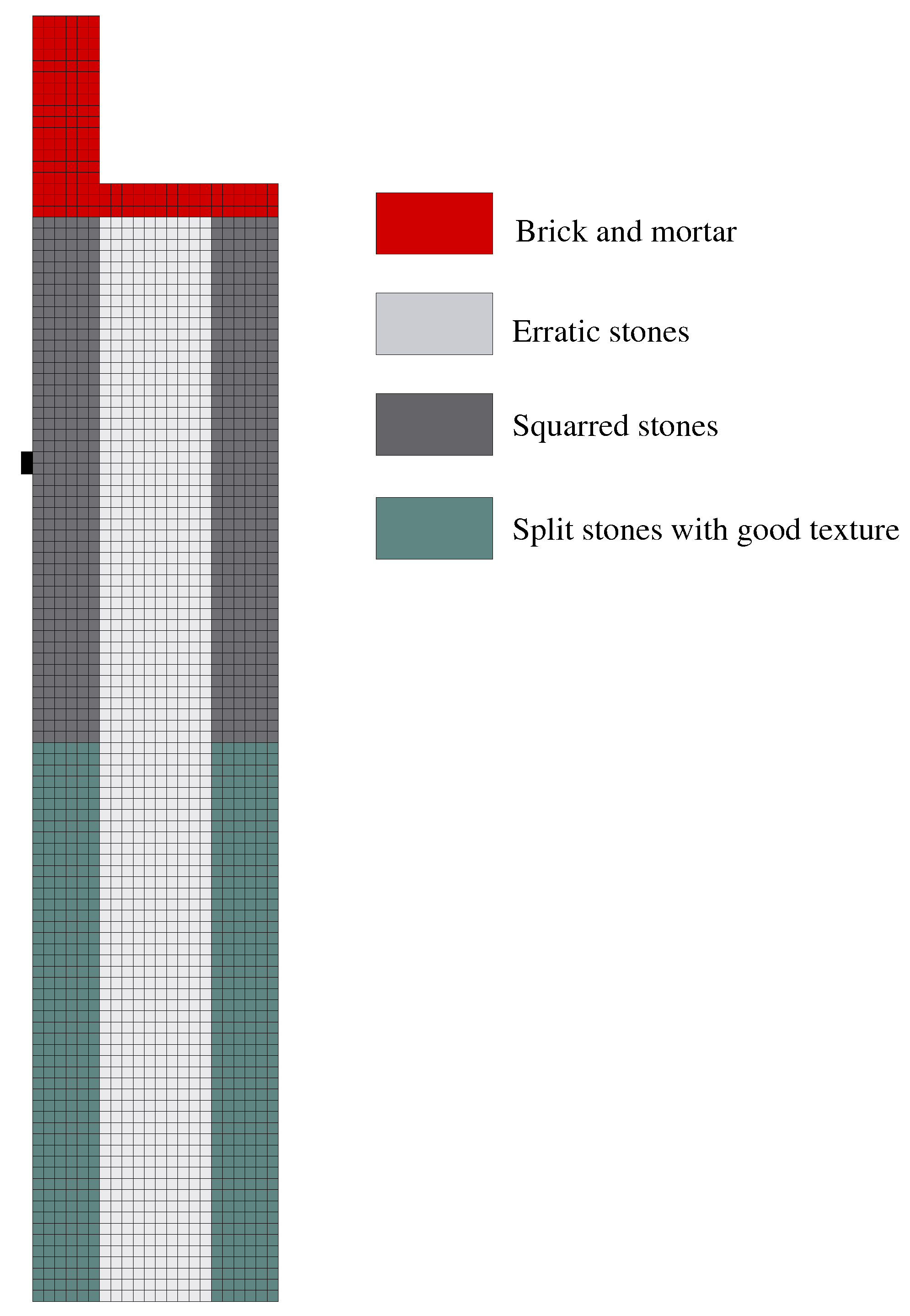
The masonry properties were obtained from the Italian building code which reports the Young’s modules and compression strength for different masonry typologies [31]. The tensile strengths were assumed to be equal to 1/10 of the compression strengths considering the common values adopted in the literature. In further detail, considering the three-leaf wall structure and the masonry textures, the values reported by the Italian code for masonry with split stones with a good texture (“muratura in pietre a spacco di buona tessitura”) were considered for the lower part of the walls. Instead, the values for masonry with squared blocks (“muratura a blocchi lapidei squadrati”) were considered for the upper part, increasing them by 50% assuming good transversal connections. Instead, the masonry properties for messy stones (“muratura in pietrame disordinata”) were considered for the wall inner core and the ones for masonry with bricks and mortar (“Muratura in mattoni pieni e malta di calce”) for the wall merlons and top.
In agreement with the code indication, an average value of the ones reported was considered for the Young’s moduli and a minimum value for the compressive strength. As regards the tensile response, the mode I fracture energies (G) were assumed to be approximately 20 N/m in agreement with the literature values [32,33,34], reasonably increasing or decreasing the value depending on the masonry typology. Table 1 summarizes the material parameters assumed.
When studying a dynamic problem such as an impact problem with high strain rates, it is important to consider the strain rate’s effects on the masonry properties. Several authors have experimentally evaluated how the strain rate affects the compression behavior of mortar and bricks [35,36] and consequently of masonry [37]. As regards the tensile response, Burnett et al. [35] evaluated how the tensile response of the masonry joints changes with the strain rate. Anyway, this study can be considered representative of the tensile masonry response considering the fact that the observations of Van Der Pluijm state that the masonry tensile response is mainly associated to the joint response [32].
In general, considering the strain rate effect, the static parameters have been multiplied by a dynamic increase factor (DIF) function of the strain rate . Equations (4)–(6) reported the DIFs’ laws obtained by Pereira and Lourenço [37] for the compressive strength (), the corresponding inelastic strain (), and the compressive fracture energy (). These laws were adopted to consider the strain rate effect on the compressive response:
As regards the tensile response, the laws obtained by Hao and Tarasov [36] for mortar compressive response were considered assuming a DIF equal for compression and tension in mortar and the masonry tensile response ruled by the mortar properties. Equation (7) was adopted for both the masonry tensile strength () and the mode I fracture energy ().
6. Finite Element Model
An explicit dynamic analysis on a 3D finite element model [38] was performed to evaluate the 3D effects of a cannon ball’s impact and the portion of wall affected by it.
6.1. Numerical Model
A portion of 20 m wall was considered, according to Pisa’s fortification geometry. The wall was constrained with rollers on the vertical edges and with continuous hinges at the bottom. Considering the symmetry of the problem, only one 10 m-long half was modeled (Figure 3) to reduce the computational effort. According to the symmetrical condition, the displacements in the direction perpendicular to the symmetry plane were constrained for the points on the same plane. Furthermore, as regards the cannon ball, only half of it was modeled and the displacements in the direction perpendicular to the plane of symmetry were constrained for the points on the same plane. The cannon ball was positioned in contact with the wall in the hitting point, fixed at 7.5 m from the ground. A uniform distribution of velocity 200 m/s, in the direction perpendicular to the wall, was assigned to all the cannon ball points.
The wall was discretized with quadratic tetrahedron (C3D10M) which was 0.5 m wide on average, in order to reduce the computational effort considering the fact that most of the wall remained elastic and almost undeformed through the entire analysis. Instead, an area which was 0.625 m wide around the impact point for the entire wall depth was discretized with elements that were 10 times smaller (Figure 3) in order to be smaller than the impacted area and obtain the high strain gradients near the impact point. The cannon ball was instead discretized with elements that were 3 cm wide, which was coherent with its geometry.
6.2. Material Constitutive Behavior
As regards the material’s constitutive behaviors, the Concrete Damage Plasticity Model was adopted for the inelastic behavior of masonry ([39,40]), available in Abaqus, whose the parameters are reported in Table 2, in agreement with the ABAQUS manual [38] and the corresponding literature values [41,42,43]. This model allows one to consider the two main failure mechanisms of masonry: cracking under tension and crushing under compression. Table 3 reports the parameters necessary to define the uni-axial compressive and tensile static responses assigned (Figure 4). The tensile response was defined in terms of cracking displacements to overcome the mesh sensitivity of the fracture energy. The damage parameters for both compression and tension were monotonically increased from 0 to 0.9 with the inelastic strains. The tensile and compressive responses were modified in function of the strain rate according to Equations (4)–(7). For the ball, an elastic–plastic behavior was defined with a yielding stress of 420 MPa.
6.3. FEM Results
The analysis stopped at 2.2 ms because some elements were excessively distorted during deformation.
Figure 5, Figure 6 and Figure 7 show, respectively, the maps of the tensile damage () of the compressive damage () and of the displacements in the direction perpendicular to the wall (U1). Considering the damage maps, two failure mechanisms coherently affected the wall with the concrete damage plasticity’s constitutive behavior. A crushing mechanism progressively affects the entire wall thickness, affecting an increasingly wider area in all three directions starting from the impact point. The damaged volume is a hemisphere with a discontinuity at the interface between the wall layers. The hemisphere damaged volume isotropically extends itself in the three directions with a compressive wave. This wave was distorted after it reached the wall’s inner core and the radius of the damaged volume instantly increased.
Figure 5 instead shows a cracking mechanism which at the beginning only affects the exterior wall face. Subsequently, the tensile damage also extends to the depth of the wall’s external curtain starting from the extreme point of the external damaged circle and slowly involving points closer to the impact point.
Regarding the displacements (Figure 7), coherently with the damage maps, the exterior face of the wall moves in the direction opposite to that of the cannon ball. Instead, from the impact point, a sphere-shaped volume extends that is pushed by the cannon ball. This volume tends to deform as soon as the displacements reach the inner core.
7. Rigid Body-Spring Model
The problem was also studied with a plane rigid body-spring model (RBSM). This model belongs to the family of discrete approaches and more specifically to those based on a square “heuristic molecule” constituting an assemblage of four rigid bodies [44]. In agreement with these approaches, a solid is discretized in quadrilateral rigid elements interacting through elastic–plastic springs. This way, the material non-linearities are concentrated in the springs whose behavior is generally independent.
7.1. Fundamental Unit of the Model
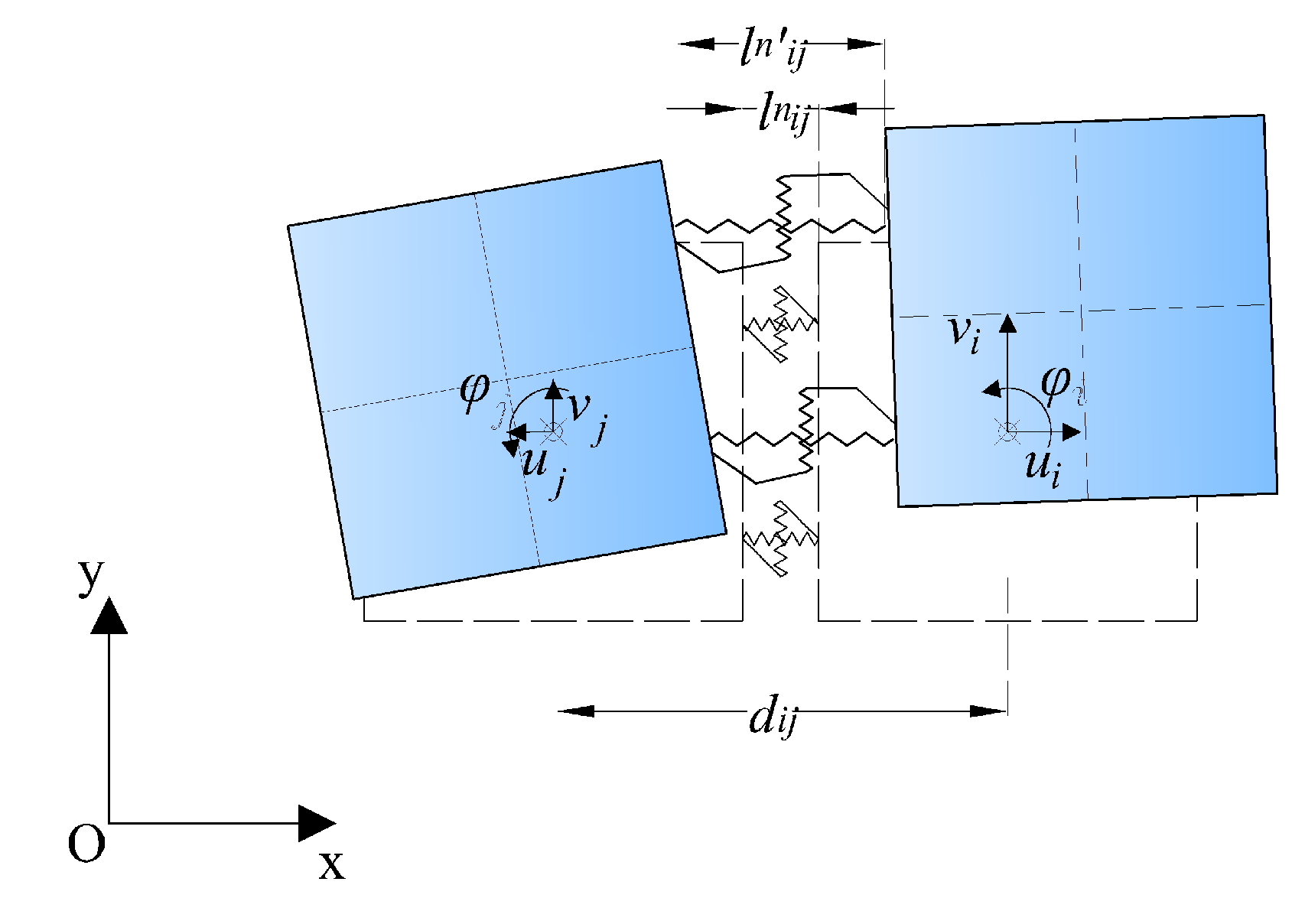
The RBSM adopted herein was developed from the quadrilateral RBSM proposed by Casolo in 2004 [19] that has been widely applied to the study of masonry structures [45]. The fundamental cell differs from the original heuristic molecula proposed by Casolo [46] for the addition of diagonal springs. These diagonal springs allow one to model isotropic materials with a Poisson’s ratio other than zero. Furthermore, the addition of the diagonal springs reduces the model failure anisotropy which is a common issue of these discrete approaches. Hence, any element is connected to the adjacent one (through two eccentric normal and shear springs) and to the one on the diagonal (through an axial spring between the element centers of gravity) (Figure 8).
The spring state is defined in function of a strain parameter that measures the spring deformation in agreement with the hypothesis of small displacements. Hence, it is defined as the ratio between the difference of displacements, in the spring direction, of the spring fixing points and the distance between the elements’ centers of gravity. In the code, the spring strain is related to the elements’ degrees of freedoms through a matrix. For example, Equation (8) reports the spring strain calculation for a normal spring according to Figure 9:
7.2. Numerical Model
The RBSM was applied to the study of a wall slice under the hypothesis of a plane strain condition, imagining the wall hit by the battery of cannons. As for the resistance, it was assigned a thickness of 5 m to the elements, also considering the results obtained with the 3D FEM and the wall volume affected by the cannon ball impact. The wall cross-section was discretized with a regular grid of square elements 0.1 m wide (Figure 10). The cannon ball was also modeled with two discrete elements which were 0.1 m wide (in black in Figure 10). These elements were connected to the wall elements in the impact point through springs with a null tensile strength, in order to reproduce a contact interaction.
An initial velocity of 200 m/s was applied to the cannon ball elements. The problem was studied with an explicit solver based on the central difference method, implemented in the specific FORTRAN code.
7.3. Spring Behavior
The model spring response was defined by assigning piece-wise laws according to the different materials that compose the three-leaf masonry. Only the initial phases after the impact were studied, hence, the strain rate effects were taken into account modifying the material properties according to Equations (4)–(7) for a strain rate of 200 s.
The spring elastic moduli were obtained by imposing the equivalence of the stored strain energy in the fundamental cell volume between the RBSM and the continuum for an isotropic material under the hypothesis of a plane strain state.
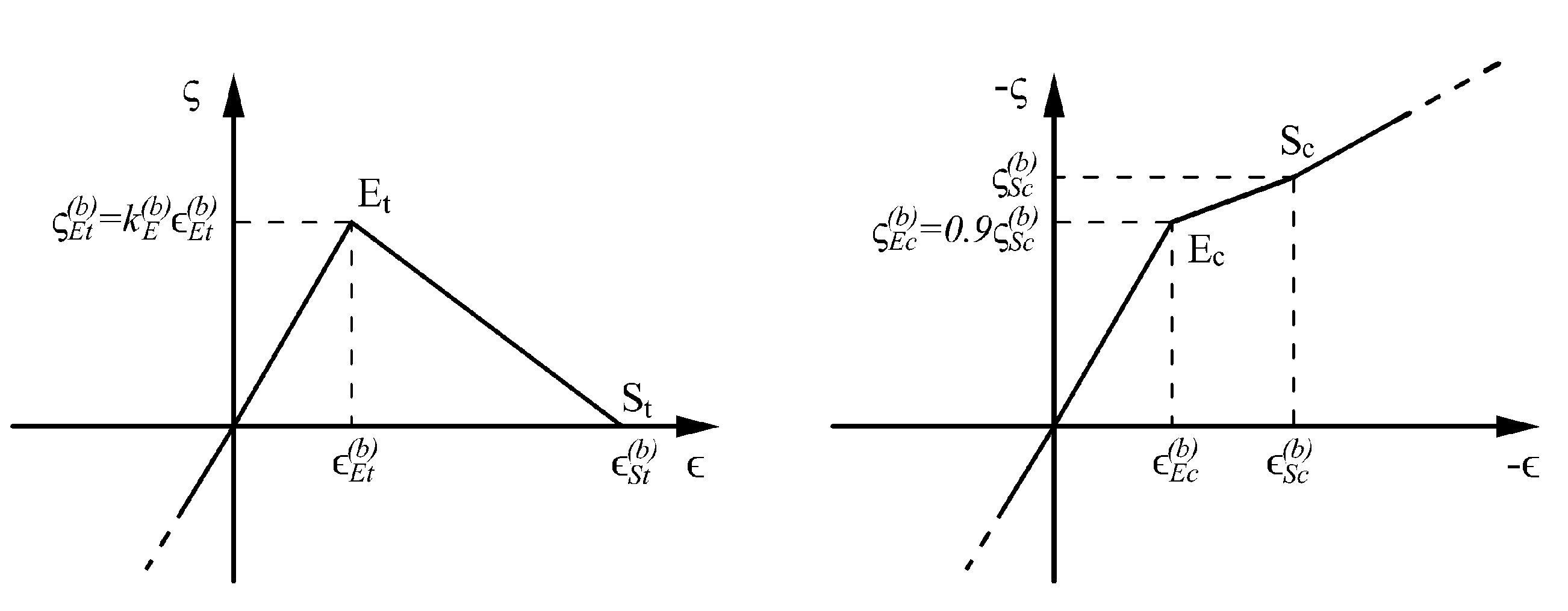
For the tensile spring response, a law with a linear softening was adopted and calibrated on the material mode I fracture energy . Instead, for the compressive response, the spring stress–strain curve at first shows a stiffness reduction in agreement with a damage mechanism for crushing, and after, the stiffness increases again (Figure 11). The increase in stiffness accounts for what happens when the masonry modeled by the spring is completely crushed, in agreement with other discrete models [47,48]. In this way, when an element is crushed, it keeps transferring the forces to the elements behind it that can resist. Coherently with the different material parameters the spring constitutive behaviors have been obtained (Table 4).
7.4. RBSM Results
The results are presented in terms of damage and displacement maps as were those for the FEM. The degree of damage of a spring was evaluated both for compression and tension according to the following formula, opportunely changing the parameters for tension and the compression:
where is the maximum average spring strain reached by the spring during its history and its initial value is . According to Equation (9), a spring is completely damaged when it reaches the S point average spring strain, both in traction and in compression. In the plot, a line perpendicular to the spring is plotted for any spring that has overcome the elastic limit, reproducing the forming crack. The color and thickness of the line depends on the spring degree of damage.
Figure 12 shows the maps of the displacements in the horizontal direction. The maps at different instants of time seem coherent with the FEM ones (Figure 7). The impact progressively affects the entire thickness of the wall. After 3 ms, all the points around the height of the impact point have been affected by the impact and as is the case in FEM, on the surface of the external leaves, some points are moving in the direction to that of the cannon ball. As such, there is an evident area whose displacement is considerably higher than in the rest of the wall.
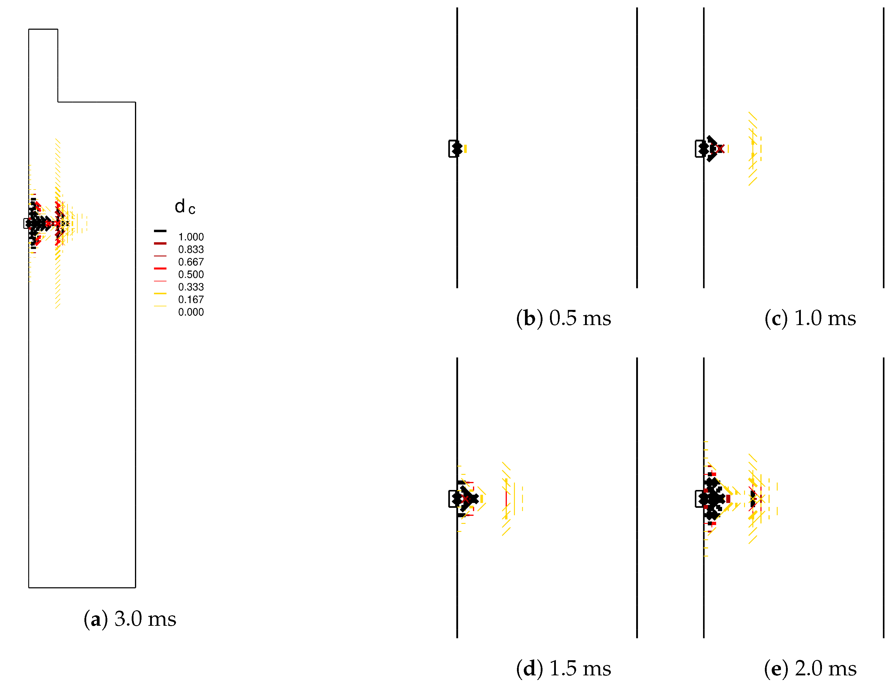
Figure 13 shows the springs damaged in compression. The damage is at first concentrated at the impact point, and a damaged area in the inner core subsequently appears, whilst the affected area progressively extends into two triangles. At 3.0 ms, there is also a wide number of diagonal springs damaged at the interface between the inner core and the external leaf.
Figure 14 shows the springs damaged in tension. The damage from the impact point progressively involves the entire thickness of the external leaf with some diagonal cracks starting from the impact point. Once the impact affects the interface between the two walls, in agreement with the displacement maps, a much wider area of the inner core is damaged with some consistent damage also at the interface between the leaves. Furthermore, this map, as was the case of the previous one, shows that many springs on the interface between the two leaves are damaged, and this can be explained by imagining a sliding mechanism at the interface between the two materials.
8. Conclusions
The paper presents an investigation into the effects of a cannon ball shot into a typical Middle Age fortification wall. The numerical results clearly show the vulnerability of this type of fortification to artillery strikes which led to the development of the bastion forts typical of the Renaissance period.
After an introduction which presents an historic reconstruction of the cannon shot and the fortification wall geometry and materials, the computations were carried out with both an FEM and an RBSM by adopting explicit dynamic solvers. The 3D FEM allowed to evaluate the amount of volume of the model that should be involved to obtain reasonable confidence in the results that can obtained by a plane RBSM.
Both the approaches proved that an iron ball impacting the wall at 200 m/s severely damages the external leaf of a three-leaf masonry. Clearly, the 3D FEM model provided a description of the impact effects in terms of the global shape of the involved damaged volume, while the RBSM allowed a better description of the damage in terms of the typology of damage thanks to the topology of the springs and a more specific material model for brittle materials. This also allowed giving a first description in terms of crack propagation. In fact, from the results, the FEM mostly associates the damage to diffuse crushing mechanisms, while instead, in the RBSM, the masonry mostly tends to be damaged for a recognizable diagonal cracking or shear sliding at the interface between the masonry leaves.
Both the models showed how the presence of a soft material such as the inner core tends to modify the impact effects, both in terms of displacement maps and in terms of damage. The affected area becomes larger and this allows one to reduce the degree of damage. This is probably the reason for the success of the embankments of the trace italianne which were built to face artillery strikes.
Author Contributions
V.T. performed the numerical analysis both with the FEM and the RBSM and wrote the original draft; S.C. supervised the research and revised the paper. All authors have read and agreed to the published version of the manuscript.
Funding
This research received no external funding.
Institutional Review Board Statement
Not applicable.
Informed Consent Statement
Not applicable.
Conflicts of Interest
The authors declare no conflict of interest.
References
- Galilei, G. Breve Instruzione all’Architettura Militare. In Le opere di Galileo Galilei; Tipografia di G. Barbera: Florence, Italy, 1891; Volume II. [Google Scholar]
- Guilmartin, J.F. Military Technology—Encyclopædia Britannica. 4 November 2020. Available online: https://www.britannica.com/technology/military-technology (accessed on 24 November 2021).
- Wei, X.; Stewart, M.G. Model validation and parametric study on the blast response of unreinforced brick masonry walls. Int. J. Impact Eng. 2010, 37, 1150–1159. [Google Scholar] [CrossRef]
- Burnett, S.; Gilbert, M.; Molyneaux, T.; Beattie, G.; Hobbs, B. The performance of unreinforced masonry walls subjected to low-velocity impacts: Finite element analysis. Int. J. Impact Eng. 2007, 34, 1433–1450. [Google Scholar] [CrossRef]
- Gilbert, M.; Hobbs, B.; Molyneaux, T. The performance of unreinforced masonry walls subjected to low-velocity impacts: Experiments. Int. J. Impact Eng. 2002, 27, 231–251. [Google Scholar] [CrossRef]
- Gilbert, M.; Hobbs, B.; Molyneaux, T. The performance of unreinforced masonry walls subjected to low-velocity impacts: Mechanism analysis. Int. J. Impact Eng. 2002, 27, 253–275. [Google Scholar] [CrossRef]
- Milani, G.; Lourenço, P.B.; Tralli, A. Homogenized rigid-plastic model for masonry walls subjected to impact. Int. J. Solids Struct. 2009, 46, 4133–4149. [Google Scholar] [CrossRef] [Green Version]
- Silva, L.C.; Lourenço, P.B.; Milani, G. Rigid block and spring homogenized model (HRBSM) for masonry subjected to impact and blast loading. Int. J. Impact Eng. 2017, 109, 14–28. [Google Scholar] [CrossRef]
- Rafsanjani, S.H.; Lourenço, P.; Peixinho, N. Dynamic interface model for masonry walls subjected to high strain rate out-of-plane loads. Int. J. Impact Eng. 2015, 76, 28–37. [Google Scholar] [CrossRef] [Green Version]
- Shi, Y.; Xiong, W.; Li, Z.X.; Xu, Q. Experimental studies on the local damage and fragments of unreinforced masonry walls under close-in explosions. Int. J. Impact Eng. 2016, 90, 122–131. [Google Scholar] [CrossRef]
- Asad, M.; Dhanasekar, M.; Zahra, T.; Thambiratnam, D. Failure analysis of masonry walls subjected to low velocity impacts. Eng. Fail. Anal. 2020, 116, 104706. [Google Scholar] [CrossRef]
- Pourfalah, S.; Cotsovos, D.M.; Suryanto, B.; Moatamedi, M. Out-of-plane behaviour of masonry specimens strengthened with ECC under impact loading. Eng. Struct. 2018, 173, 1002–1018. [Google Scholar] [CrossRef]
- Casolo, S.; Milani, G. Simplified out-of-plane modelling of three-leaf masonry walls accounting for the material texture. Constr. Build. Mater. 2013, 40, 330–351. [Google Scholar] [CrossRef]
- Tiberti, S.; Milani, G. 3D homogenized limit analysis of non-periodic multi-leaf masonry walls. Comput. Struct. 2020, 234, 106253. [Google Scholar] [CrossRef]
- Lewtas, I.; McAlister, R.; Wallis, A.; Woodley, C.; Cullis, I. The ballistic performance of the bombard Mons Meg. Def. Technol. 2016, 12, 59–68. [Google Scholar] [CrossRef] [Green Version]
- Clifford, J.R. Gunpowder Artillery in Europe, 1326–1500: Innovation and Impact. In Technology, Violence, and War; Ehlers, R.S., Jr., Douglas, S.K., Curzon, D.P.M., Eds.; BRILL: Leiden, The Netherlands, 2019. [Google Scholar] [CrossRef]
- Casolo, S.; Milani, G.; Tateo, V. Analysis of damage due to artillery strikes on two types of fortress typical of the middle ages and of the renaissance periods. In Proceedings of the 7th International Conference on Computational Methods in Structural Dynamics and Earthquake Engineering Methods in Structural Dynamics and Earthquake Engineering, Eccomas Proceedia, Crete, Greece, 24–26 June 2019; Volume 1, pp. 1344–1355. [Google Scholar] [CrossRef] [Green Version]
- Kakaliagos, A.; Ninis, N. Damage and failure of Orban’s gun during the bombardment of Constantinople walls in 1453. Frat. Integrità Strutt. 2019, 13, 481–496. [Google Scholar] [CrossRef] [Green Version]
- Casolo, S. Modelling in-plane micro-structure of masonry walls by rigid elements. Int. J. Solids Struct. 2004, 41, 3625–3641. [Google Scholar] [CrossRef]
- Casolo, S. Macroscopic modelling of structured materials: Relationship between orthotropic Cosserat continuum and rigid elements. Int. J. Solids Struct. 2006, 43, 475–496. [Google Scholar] [CrossRef] [Green Version]
- Casolo, S. Macroscale modelling of microstructure damage evolution by a rigid body and spring model. J. Mech. Mater. Struct. 2009, 4, 551–570. [Google Scholar] [CrossRef] [Green Version]
- Biolzi, L.; Casolo, S.; Diana, V.; Sanjust, C. Estimating laminated glass beam strength via stochastic Rigid Body-Spring Model. Compos. Struct. 2017, 172, 61–72. [Google Scholar] [CrossRef]
- Krebs, R.E. Groundbreaking Scientific Experiments, Inventions, and Discoveries of the Middle Ages and the Renaissance; Greenwood Publishing Group: London, UK, 2004. [Google Scholar]
- Manucy, A.C. Artillery through the Ages A Short Illustrated History of Cannon, Emphasizing Types Used in America; Interpretive Series, History, 1; National Park Service: Washington, DC, USA, 1949.
- Gentile, M.L. Gli Annales Pisani di Bernardo Maragone; Nicola Zanichelli: Bologna, Italy, 1930–1936. [Google Scholar]
- Associazione AMUR, Associazione per le Mura di Pisa. Available online: https://www.muradipisa.it/le-mura/ (accessed on 8 October 2021).
- Napolitano, D. Mura di Pisa, Vista da Largo Zan Zeno. Available online: https://commons.wikimedia.org/wiki/File:Mura_di_Pisa,_Vista_da_Largo_Zan_Zeno.jpg (accessed on 7 October 2021).
- Clephan, R.C. The Ordnance of the Fourteenth and Fifteenth Centuries. Archaeol. J. 1911, 68, 49–138. [Google Scholar] [CrossRef]
- Tartaglia, N. La Nova Scientia; Arnaldo Forni Editore: Bologna, Italy, 1984. [Google Scholar]
- NASA. Drag on a Sphere. Available online: https://www1.grc.nasa.gov/beginners-guide-to-aeronautics/drag-of-a-sphere/ (accessed on 5 October 2021).
- Ministero delle Infrastrutture e dei Trasporti. Aggiornamento delle Norme Tecniche per le Costruzioni, Decreto Ministeriale 17 Gennaio 2018. Gazzetta Ufficiale n. 42, Suppl. Ordinario. 20 February 2018. Rome, Italy. Available online: https://www.gazzettaufficiale.it/eli/gu/2018/02/20/42/so/8/sg/pdf (accessed on 24 November 2021). (In Italian)
- Van der Pluijm, R. Non-linear Behaviour of Masonry under Tension. Heron 1997, 42, 25–54. [Google Scholar]
- Reyes, E.; Casati, M.; Gálvez, J. Cohesive crack model for mixed mode fracture of brick masonry. Int. J. Fract. 2008, 151, 29–55. [Google Scholar] [CrossRef]
- Schneemayer, A.; Schranz, C.; Kolbitsch, A.; Tschegg, E.K. Fracture-Mechanical Properties of Mortar-to-Brick Interfaces. J. Mater. Civ. Eng. 2014, 26, 04014060. [Google Scholar] [CrossRef]
- Burnett, S.; Gilbert, M.; Molyneaux, T.; Tyas, A.; Hobbs, B.; Beattie, G. The response of masonry joints to dynamic tensile loading. Mater. Struct. Constr. 2007, 40, 517–527. [Google Scholar] [CrossRef]
- Hao, H.; Tarasov, B. Experimental Study of Dynamic Material Properties of Clay Brick and Mortar at Different Strain Rates. Aust. J. Struct. Eng. 2008, 8, 117–132. [Google Scholar] [CrossRef]
- Pereira, J.; Lourenço, P. Experimental characterization of masonry and masonry components at high strain rates. J. Mater. Civ. Eng. 2017, 29, 04016223. [Google Scholar] [CrossRef] [Green Version]
- Smith, M. ABAQUS Analysis User’s Guide, Version 2016; Dassault Systèmes Simulia Corp: Providence, RI, USA, 2016. [Google Scholar]
- Lubliner, J.; Oliver, J.; Oller, S.; Oñate, E. A plastic-damage model for concrete. Int. J. Solids Struct. 1989, 25, 299–326. [Google Scholar] [CrossRef]
- Lee, J.; Fenves, G. Plastic-damage model for cyclic loading of concrete structures. J. Eng. Mech. 1998, 124, 892–900. [Google Scholar] [CrossRef]
- Sarhosis, V.; Milani, G.; Formisano, A.; Fabbrocino, F. Evaluation of different approaches for the estimation of the seismic vulnerability of masonry towers. Bull. Earthq. Eng. 2018, 16, 1511–1545. [Google Scholar] [CrossRef] [Green Version]
- De Iasio, A.; Wang, P.; Scacco, J.; Milani, G.; Li, S. Longhu pagoda: Advanced numerical investigations for assessing performance at failure under horizontal loads. Eng. Struct. 2021, 244, 112715. [Google Scholar] [CrossRef]
- Sferrazza Papa, G.; Tateo, V.; Parisi, M.; Casolo, S. Seismic response of a masonry church in Central Italy: The role of interventions on the roof. Bull. Earthq. Eng. 2021, 19, 1151–1179. [Google Scholar] [CrossRef]
- Casolo, S. A linear-elastic heuristic-molecular modelling for plane isotropic micropolar and auxetic materials. Int. J. Solids Struct. 2021, 224, 111042. [Google Scholar] [CrossRef]
- Casolo, S.; Peña, F. Rigid element model for in-plane dynamics of masonry walls considering hysteretic behaviour and damage. Earthq. Eng. Struct. Dyn. 2007, 36, 1029–1048. [Google Scholar] [CrossRef]
- Casolo, S.; Milani, G.; Uva, G.; Alessandri, C. Comparative seismic vulnerability analysis on ten masonry towers in the coastal Po Valley in Italy. Eng. Struct. 2013, 49, 465–490. [Google Scholar] [CrossRef]
- Cusatis, G.; Pelessone, D.; Mencarelli, A. Lattice Discrete Particle Model (LDPM) for failure behavior of concrete. I: Theory. Cem. Concr. Compos. 2011, 33, 881–890. [Google Scholar] [CrossRef]
- Gedik, Y.H.; Nakamura, H.; Yamamoto, Y.; Kunieda, M. Evaluation of three-dimensional effects in short deep beams using a rigid-body-spring-model. Cem. Concr. Compos. 2011, 33, 978–991. [Google Scholar] [CrossRef]
Figure 1.
A photo of the Pisa fortification, reprinted with permission from ref. [27]. Licensed under the Creative Commons Attribution-Share Alike 4.0 International license. (a) and a reconstruction of the wall cross-section (b)—measured in meters.
Figure 1.
A photo of the Pisa fortification, reprinted with permission from ref. [27]. Licensed under the Creative Commons Attribution-Share Alike 4.0 International license. (a) and a reconstruction of the wall cross-section (b)—measured in meters.

Figure 2.
Comparison of the trajectories computed considering or neglecting the drag force. The computed graphs consider an iron ball (7800 kg/m) with the diameter D equal to 20 cm, a muzzle velocity of 300 m/s, and an initial angle of 12°.
Figure 2.
Comparison of the trajectories computed considering or neglecting the drag force. The computed graphs consider an iron ball (7800 kg/m) with the diameter D equal to 20 cm, a muzzle velocity of 300 m/s, and an initial angle of 12°.

Figure 3.
Finite element model mesh: (a) front view and (b) side view.

Figure 4.
Shape of the uni-axial post-elastic responses for traction and compression defined for the masonry materials. For graphical reasons, the compressive stress–strain values are plotted as positives.
Figure 4.
Shape of the uni-axial post-elastic responses for traction and compression defined for the masonry materials. For graphical reasons, the compressive stress–strain values are plotted as positives.

Figure 5.
Maps of the tensile damage () and zoom on the impact point at different instants of time.

Figure 6.
Maps of the compressive damage () and zoom on the impact point at different instants of time.
Figure 6.
Maps of the compressive damage () and zoom on the impact point at different instants of time.

Figure 7.
Maps of the displacements in the direction of motion of the ball and zoom on the impact point at different instants of time.
Figure 7.
Maps of the displacements in the direction of motion of the ball and zoom on the impact point at different instants of time.

Figure 8.
Fundamental cell of the RBSM with diagonal springs.

Figure 9.
Strain measure of the model springs.

Figure 10.
RBSM discretization and materials.

Figure 11.
Spring stress–strain curves defined for traction and compression. For graphic reasons, the compressive stress–strain values are plotted as positives.
Figure 11.
Spring stress–strain curves defined for traction and compression. For graphic reasons, the compressive stress–strain values are plotted as positives.

Figure 12.
Deformed shape and maps of the displacements in the horizontal direction and zoom on the impact point at different instants of time.
Figure 12.
Deformed shape and maps of the displacements in the horizontal direction and zoom on the impact point at different instants of time.

Figure 13.
Maps of the compressive spring damage () and zoom on the impact point at different points in time.
Figure 13.
Maps of the compressive spring damage () and zoom on the impact point at different points in time.

Figure 14.
Maps of the tensile spring damage () and zoom on the impact point at different points in time.
Figure 14.
Maps of the tensile spring damage () and zoom on the impact point at different points in time.


Table 1.
Masonry’s assumed static material properties.
| Masonry | E (MPa) | f (MPa) | f (MPa) | G (N/m) |
|---|---|---|---|---|
| Split stones with good texture | 1740 | 2.6 | 0.26 | 20 |
| Squared stones | 2850 | 5.8 | 0.58 | 25 |
| Messy stones | 870 | 1.0 | 0.10 | 15 |
| Bricks and mortar | 1500 | 2.6 | 0.26 | 20 |
Table 2.
Parameters of the concrete damage plasticity constitutive model.
| Dilatation Angle | Eccentricity | K | Viscosity Parameter | |
|---|---|---|---|---|
| 15° | 0.1 | 1.16 | 0.667 | 1 × 10 |
Table 3.
Uniaxial compressive and tensile static responses for different masonry typologies.
| Material | (mm) | (mm) | ||
|---|---|---|---|---|
| Split stones with good texture | 0.134 | 2.660 | 0.064 | 0.449 |
| Squared stones | 0.183 | 2.170 | 0.022 | 0.151 |
| Erratic stones | 0.103 | 2.970 | - | 0.500 |
| Bricks and mortar | 0.156 | 2.440 | 0.064 | 0.449 |
Table 4.
RBSM spring constitutive behaviors for the different materials.
| Split stones with good Texture | ||||
| Normal | Diagonal | |||
| Points | (MPa) | (MPa) | ||
| Compressive | ||||
| E | 2.39 | 3.70 | 2.39 | 3.70 |
| S | 13.00 | 4.11 | 26.00 | 4.11 |
| Tensile | ||||
| E | 0.36 | 0.56 | 0.36 | 0.56 |
| S | 0.58 | 0.00 | 1.15 | 0.00 |
| Squared stones | ||||
| Normal | Diagonal | |||
| Points | (MPa) | (MPa) | ||
| Compressive | ||||
| E | 1.84 | 8.25 | 1.84 | 8.25 |
| S | 13.00 | 9.16 | 26.00 | 9.16 |
| Tensile | ||||
| E | 0.49 | 1.24 | 0.49 | 1.24 |
| S | 0.19 | 0.00 | 0.39 | 0.00 |
| Erratic stones | ||||
| Normal | Diagonal | |||
| Points | (MPa) | (MPa) | ||
| Compressive | ||||
| E | 1.84 | 1.42 | 1.84 | 1.42 |
| S | 13.00 | 1.58 | 26.00 | 1.58 |
| Tensile | ||||
| E | 0.28 | 0.21 | 0.28 | 0.21 |
| S | 1.88 | 0.00 | 3.75 | 0.00 |
| Bricks and mortar | ||||
| Normal | Diagonal | |||
| Points | (MPa) | (MPa) | ||
| Compressive | ||||
| E | 2.77 | 3.70 | 2.77 | 3.70 |
| S | 13.00 | 4.11 | 26.00 | 4.11 |
| Tensile | ||||
| E | 0.42 | 0.59 | 0.42 | 0.59 |
| S | 0.58 | 0.00 | 1.15 | 0.00 |
Publisher’s Note: MDPI stays neutral with regard to jurisdictional claims in published maps and institutional affiliations. |
© 2021 by the authors. Licensee MDPI, Basel, Switzerland. This article is an open access article distributed under the terms and conditions of the Creative Commons Attribution (CC BY) license (https://creativecommons.org/licenses/by/4.0/).
Share and Cite
MDPI and ACS Style
Tateo, V.; Casolo, S. Explicit Dynamic Analysis by a Rigid Body-Spring Model of Impact Loads of Artillery on Middle Age Fortifications. Buildings 2021, 11, 607. https://doi.org/10.3390/buildings11120607
AMA Style
Tateo V, Casolo S. Explicit Dynamic Analysis by a Rigid Body-Spring Model of Impact Loads of Artillery on Middle Age Fortifications. Buildings. 2021; 11(12):607. https://doi.org/10.3390/buildings11120607
Chicago/Turabian StyleTateo, Vito, and Siro Casolo. 2021. "Explicit Dynamic Analysis by a Rigid Body-Spring Model of Impact Loads of Artillery on Middle Age Fortifications" Buildings 11, no. 12: 607. https://doi.org/10.3390/buildings11120607
Note that from the first issue of 2016, this journal uses article numbers instead of page numbers. See further details here.