Preparation and Melting of Scrap in Aluminum Recycling: A Review


Department of Management and Engineering, University of Padova, Stradella S. Nicola, 3 I-36100 Vicenza, Italy
*
Author to whom correspondence should be addressed.
Metals 2018, 8(4), 249; https://doi.org/10.3390/met8040249
Submission received: 9 January 2018
/
Revised: 15 March 2018
/
Accepted: 29 March 2018
/
Published: 8 April 2018
Abstract
:This work provides an overview of the aluminum (Al) recycling process, from the scrap upgrading to the melting process. Innovations and new trends regarding the Al recycling technologies are highlighted. Aluminum recycling offers advantages in terms of environmental and economic benefits. The presence of deleterious impurities in recycled Al alloys is increasing and this is the main drawback if compared to primary alloys. The continuous growth of undesired elements can be mitigated by different technologies, preliminary operations and treatments, and by the optimization of the melting process. Downgrading and dilution are possible solutions to reduce the rate of impurities, but they are not sustainable if the final use of Al alloy continuously increases. The main objectives in the development of the Al recycling are shown and discussed. In particular, the evolution of preliminary treatments of the scrap, as sorting, comminution and de-coating, is reported and a review of the melting technologies is also presented. However, the choice of performing preliminary operations to the melting stage, thus improving the operating conditions during the furnace running, is a trade-off between costs and process efficiency.
1. Introduction
Aluminum (Al) is the second most plentiful metallic element on earth. It has grown to be a great competitor for engineering applications since the end of 19th century, when it became economically viable [1]. Aluminum is a light, conductive, and corrosion resistant metal with strong affinity for oxygen. This combination of properties has allowed aluminum to compete for a large number of applications [2]. Currently, aluminum is the most widely used non-ferrous metal in the world, being present in different sectors such as transportation, packaging, construction, electricity, and medicine. The need for improved mechanical properties and new applications has led to the continuous development of new kinds of Al alloys with specific chemical composition [2].
Although aluminum is one of the most common elements on earth, it is too reactive with other elements to occur naturally. Bauxite ore is the primary source of alumina, i.e., aluminum oxide (Al2O3). The Bayer process, invented and patented in 1887, is the primary process by which alumina is extracted from bauxite ore and separated from red mud [3]. The Hall–Héroult process, simultaneously discovered in 1886 by Charles Martin Hall and Paul Héroult, allows aluminum to be refined from alumina by means of electrolysis. Alumina is dissolved in a cryolite (Na3AlF6) bath with various fluoride salt additions in order to control the bath temperature, density, resistivity, and alumina solubility. Larger and more efficient plants have been developed and the process control has been improved, but the production concept remains basically unchanged [4,5].
This is the primary route for Al production but a secondary route is available using Al scrap and recycling. It is claimed that recycling saves resources, decreases the need for landfill space and, in the case of non-renewable resources, such as metals, prolongs the necessary period to deplete them.
2. Recycling Strategy
Compared to other high-volume materials, such as copper (Cu), zinc (Zn), magnesium (Mg), and steel, Al production has one of the widest energy differences between the primary and secondary routes, but not the main recycled fraction, that is the share of secondary production with respect to the total one (Figure 1). The recycled Al fraction is about 35%, which is close to the values of recycled Mg and Zn (~30%). Nowadays, copper and steel remain the materials with the highest impact in terms of recycled amounts (~40%).
On the other side, Al recycling allows a reduction of 95% of the required energy [8], the highest value when compared to Mg, Cu, Zn and steel (see Figure 1), and emits only 5% of the greenhouse gas [9]. The production of secondary aluminum is estimated to consume an energy amount between 5 and 7 GJ/ton due to recent improvements. Furthermore, one ton of recycled aluminum saves up to 8 metric tons of bauxite, 14,000 kWh of energy, 6300 liters of oil, 7.6 m3 of landfill, and the average total exhaust emission is about 350 kg of CO2 [7]. Dust and air emissions from scrap processing are generally at a low level. However, the emission of hazardous air pollutants (e.g., dioxins and furans) may be generated during melting operations. Emissions from the furnace are being managed by means of suitable process control and special flue gas treatments.
The main waste of secondary Al production is the non-metallic residue coming from scrap smelting. It is often termed “salt cake” or “salt slag” and contains 5–7% of residual metallic aluminum, 15–30% aluminum oxide, 30–55% sodium chloride, 15–30% potassium chloride and, depending on the initial scrap type, carbides, nitrides, sulfides, and phosphides [10]. The formation and recovery of salt slag must be considered from an environmental point of view because it is classified as toxic and hazardous waste; landfill disposal is forbidden in most of the European countries and it should be recycled and processed properly.
The chemical composition is the main challenge in Al recycling. Scrap originates from different Al alloys, with different alloying elements, in different amounts [11]. This means that it is difficult to control the level of impurities but also difficult to obtain the targeted alloy composition. Both wrought and foundry alloys can be obtained by recycling, but they strongly differ. Casting alloys have higher alloying content than wrought ones. While the formers have a concentration of elements up to 20 wt %, the wrought alloys have up to 10 wt % [12]. This difference distinguishes the recycling processes from the production process.
Remelters produce wrought alloys, usually in the form of extrusion billets and rolling ingots, from mainly clean and sorted wrought alloy scrap. Contrary, refiners are able to add alloying elements and to remove some undesired elements after the melting process, thus producing foundry alloys and de-oxidized metal from different types of scrap [13].
The feature of Al to absorb foreign and undesired elements, which are not normally described in the international standards, is sometimes a handicap. To remove impure elements from a molten bath is impractical or inconvenient. As a result, the scrap is usually recycled, which avoids the refinement stage. Two possible solutions are currently followed, i.e., downgrading and dilution. By downgrading, the low-alloyed scrap is used to obtain alloys with higher alloying contents, while, by dilution, the molten scrap is diluted with primary Al or low-alloyed scrap to reduce the concentration of elements below critical levels.
These strategies will gradually lead to a non-recyclable scrap surplus if no other solutions are considered [14]. Alternatives may come from a greater standardization of the commercial alloys and, where possible, a wider range of accepted impurities. However, this is possible only with the definition of new regulations [15].
A sustainable solution is the improvement of the efficiency of Al recycling in the production chain, which includes the melting process but also several preliminary treatments of the scrap, such as sorting, comminution, and thermal treatments, as shown in the flow chart of Figure 2. All of these stages lead to an increase in cost but, on the other hand, they improve the scrap quality in terms of metal yield and recyclability.
The selection of the melting furnace is a critical aspect and it depends on the quality and quantity of the scrap [16,17]. Each solution has the same objective: generate the highest melting capacity per unit volume while maximizing the thermal efficiency in order to reduce the fuel cost and cycle time.
In order to minimize the dissolution and amount of hydrogen in the bath and the metal loss, and to remove metallic and non-metallic impurities, fluxing and refining are generally used. These techniques refer to the addition of chemical compounds to clean the molten bath and prevent the formation of oxide.
In the next sections, the main treatments used to upgrade the scrap are critically reviewed and discussed, considering both the consolidated technologies and the innovative solutions. In addition, the melting phase is critically analyzed in terms of technological evolution and furnace selection, as it is the most important choice to optimize the melting rate. Fluxing and slag treatments have also been considered to complete the production chain.
3. Secondary Aluminum Alloys
The treatment of Al scrap to produce new Al metal and alloys is an alternative to primary Al production. The chemical composition of the alloys is strictly related to the scrap quality. Therefore, recycled aluminum presents a certain amount of impurities, generally not present in primary alloys, and the alloying elements are more difficult to manage.
Nowadays, this distinction is not completely exhausting. By properly selecting high quality scrap, a purity level close to primary alloys can be achieved in secondary alloys too.
Iron (Fe) plays an important role in distinguishing between primary and secondary Al alloys. This element cannot be easily removed from the molten metal and it forms generally brittle intermetallic compounds that influence the final mechanical properties of the components [18].
Primary Al alloys present low Fe content and so they are used for applications where the best exploitation of some specific properties is required (mechanical strength, ductility, corrosion resistance, workability, weldability, electrical conductivity); secondary alloys show good castability, which, combined with the natural low volume density of Al alloys, makes them suitable in high-pressure die casting.
4. Industry and Recycling Trend
Figure 3 shows the production of secondary aluminum in Europe and United States of America. The contribution of individual European countries is also analyzed. While the production is almost steady in the USA, a continuous growth is evident in Europe, with a production of more than 3 million metric tons in 2014. About half of the total production is concentrated in Germany and Italy. In the considered period, Italy doubled its production from about 500 to 1000 thousand metric tons, becoming the main European producer. Austria, Spain, and Hungary show similar trends with a strong increment in recent years, while France and the Netherlands show an opposite trend. Norway in 2014 recorded a quadruple production increase compared to 1998, but the progress decreases over the next few years until 2014.
5. Raw Material: Al Scrap
Scrap is the raw material of Al recycling. It can be modeled depending on the product, the time, and the rate at which material becomes available for recycling. It is generally accepted that rolled aluminum components in buildings, automobiles, and beverage cans have useful lives that are respectively ~50, ~15, and ~0.2 years. Therefore, the amount of scrap released into the market is known and can be forecast. The useful lifetime can be estimated and used to determine when the material becomes available as postconsumer scrap.
The global collection rate of Al from building industry is about 85%, while the amount of Al packaging effectively recycled depends greatly upon individual national circumstances. Therefore, the rates vary from 25% to 85% across the world. In Europe, more than 28 billion used beverage cans (UBCs) were recycled in 2016 [20]. Their metal stays in the European circular economy and remains available to produce new Al products. The collected UBCs represent one of the most important sources of Al scrap, with a total amount of about 400,000 tons of recycled material.
The overall recycling rate for automotive aluminum was found to be 91% in 2017 [21]. The transport sector has high rate of recycling because dismantlers and recyclers recognize the high intrinsic value of end-of-life aluminum products. In general, end-of-life vehicles are delivered for dismantling, which represents an effective “source” of Al scrap both in Europe and the USA. Once the fluids (e.g., oils, lubricants) are drained, and the high value and hazardous components are removed from the car and distributed to the appropriate consumers or handlers, scrap of known composition, such as aluminum alloy wheels, and, in some cases mixed scrap, are sold to scrap dealers. The purchased scrap are then sent to shredders, or directly to a recovery operation, thus entering into the recycling flow.
However, most of the scrap is internal and not considered in the statistics. Some amount of aluminum recycling has always occurred. Producers remelt internal scrap, and foundries remelt gates and risers and scrap castings.
Aluminum scrap is often categorized as “new scrap” and “old scrap” [22]. New scrap originates during the manufacturing of Al semi-fabricated and final products (shavings, off-cuts, molded parts, etc.) where the quality and composition are usually known. In general, new scrap is molten without any preliminary treatment.
Old scrap refers to those products collected after disposal from consumers, thus at the end of their life, e.g., cables, pots, radiators, etc. (see Figure 4). This raw material is more contaminated than new scrap and preliminary treatments of the scrap are generally necessary.
Figure 5 shows the amounts of new and old scrap on the whole production of secondary aluminum in the United States of America. It is evident that the most essential input material to the Al recycling process remains metal recovered from the fabrication of aluminum scrap.
An exhaustive classification of the Al scrap is described in the standards EN 12258 and EN 13920 [22,23], where the characteristics, the chemical compositions, and the metal yield are provided for each category. The metal yield indicates the portion of a scrap consignment that becomes useable metal after proper melting. Table 1 reports a short summary of the different types of Al scrap with the main characteristics.
The categories differ not only in their origin and chemical composition, but in the amount of entrapped oxides and foreign materials too. This is a key aspect as it strongly affects the melting process. Firstly, dirtier scrap requires the use of rotary furnaces, precluding the possibility to use reverberatory ones, which has a deep impact on the efficiency of the process and on the issue of environmental impact. The scrap quality also limits the quality and composition of the final alloy. An Al alloy with low levels of iron and inclusions cannot be realized if the initial scrap shows low metal yield and a great amount of foreign material. The available cost of the scrap is also reported in Table 1 because it represents a key feature for refiners, more than labor or energy costs.
6. Preliminary Treatments of Al Scrap
The different amount of available metal and impurity in the Al scrap depend on the origin of the scrap itself. However, these characteristics can be changed before the melting process by means of specific treatments. The principal preliminary treatments applied to Al scrap are hereafter discussed even if the objectives of all these processes are: increasing the bulk density, removing non-aluminum scrap, and reducing the impurity level.
6.1. Comminution
The scrap occurs in a great variety of shapes and dimensions, so the comminution is aimed to reduce this scatter. The objectives of comminution are:
- To obtain a proper distribution of scrap size, which is required by the subsequent steps;
- To increase the bulk density;
- To liberate components that form assemblies.
The comminution can directly affect the melting rate with the scrap size [25], but the main advantage is the possibility to remove undesired materials as rubber, magnesium, and zinc parts from the Al alloy [26].
Comminution is typically used in mining processes, so results and modeling are usually referred to as brittle materials. There is poor knowledge about the comminution of non-brittle materials. Scrap streams have different properties than natural minerals, such as large particle size, high ductility, and more heterogeneity in size and shape [27].
The characteristics usually considered to evaluate the results of the comminution are the fragments’ size and mass distribution as well as their median values. In order to calculate the fragments’ size, three main dimensions a, b, and c should be considered, whereby the rule a > b > c has to be fulfilled. The b dimension has been established to be indicative for the fragment size. The evaluation of the deformation process can be carried out through the degree of bending and the degree of compaction, as defined by Schubert et al. [28].
A variety of machines and equipment are available on the market, specifically rotary shears [29], rotary cutters [30], translator shears (guillotine, alligator), and rotary shredders [31] (Figure 6). All of these differ by the technology and by the type of load applied to the scrap. In the context of Al scrap comminution, the cutting, shearing, tearing, and bending stresses are suitable. Swing-hammer shredders have found the greatest diffusion as they guarantee both the specific size’s distribution and the liberation of assembled parts.
The main efforts to improve the comminution process are focused on a reduction of energy consumption and an increase in the lives of the machines. For the first topic, the increase of the angular speed leads to a reduction of the whole energy consumption. Therefore, the swing-hammer shredders should be operated at the highest possible velocity, even if lower speeds mean lower wear, lower dust, and lower noise emission [32].
Nowadays, other processes cannot substitute mechanical comminution because it achieves the desired results with a higher rate. However, alternative processes may be used in order to separate Al scrap from other materials. For instance, high-pressure water-jets can be used to obtain a better disassembly of products [33,34]. For the separation of surface contaminations or the removal of rubber from Al assembly, selective liberation by high-pressure water-jets is particularly suitable.
High-pressure water-jet comminution is a branch of high-pressure water-jet technology, which has been widely used in many different technical fields, for example in cutting as well as for the abrasive stressing of surfaces. During high-pressure water-jet comminution, most particles are broken into smaller ones instantly by the high-speed impact of these particles against a target. The velocity of the high-speed water-jet can reach values of up to about 800 m/s and a specific power of about 200 kW/mm2 [34].
Several advantages can be mentioned, such as low energy consumption and high comminution efficiency, no product contamination, no dust problem or environmental pollution, and lower equipment wear. However, the set up process is not easy and several parameters have to be preliminarily optimized for the specific application, such as the pump pressure, the mass flow rate, the diameter of feed material particle, the standoff distance, the loading times, the hardness of the target, and the impact angle.
Even if high-pressure water-jets cannot replace the existing comminution processes, this process is applied to the disassembly of washing machines, car seats, and computers [34].
In order to optimize the comminution process, a new integrated design of products should be developed and introduced from the beginning. It has been demonstrated that avoiding the chemical joints between compatible and incompatible materials for recycling, and minimizing the number of physical joints, can increase the efficiency of the comminution process [35].
6.2. Sorting
Aluminum alloys are used in several sectors and applications in combination with a lot of different materials, such as metals (steel, copper, zinc) or, in other cases, rubber, plastic, and glass. The Al scrap inevitably contains residuals of such materials that oblige refiners to properly screen the scrap before melting to enhance recycling efficiency and reduce the presence of impure elements.
Undesired particles and elements may be reduced during the melting by refining processes [36], but this is challenging due to thermodynamic barriers. The physical separation (sorting) of solid scrap streams is a reliable solution to prevent the commingling of metals and elements, even if the technical benefits are not completely evident. Different types of scrap require various sorting methods and different results can be obtained. Thus, it is necessary to understand when the benefits outweigh the required investment [37].
Sorting casting and wrought Al alloys, for instance, allows the production of high quality wrought alloys that are actually not possible with mixed scrap, however, sorting technologies for this issue have high capital investments and high running costs.
Table 2 summarizes the main sorting technologies, highlighting both consolidated and innovative methods. The sorting technologies normally used for Al recycling aim to separate aluminum scrap from other materials, such as other metals or rubber. The research and the innovative technologies are now oriented not only to separate Al scrap, but to recognize the alloy group and, if possible, the specific Al alloy.
6.2.1. Magnetic Separation
Magnetic separation is one of the oldest forms of material separation and it has existed in the mineral processing industry since the early 1900s. It is a way to divide non-ferrous from ferrous components and it is extensively used in secondary Al industry. A wide variety of separators are available to perform this task. The most common are drum magnets and overhead belt magnets (see Figure 7), which differ mainly for the plant layout. The scrap moves on a conveyor belt and it passes near a permanent NdFeB magnet. This generates a magnetic field responsible for an attractive force approaching ferromagnetic materials. Non-magnetic particles are unaffected by the magnet. Thus, the sorted scrap may still contain many non-magnetic contaminates [38].
The magnetic separation is widely used for sorting UBCs, this process provides the most compact and efficient method of sorting aluminum and steel cans. In general, two cycles of magnetic separation are planned for cleaning UBC scrap. Furthermore, most municipal recycling facilities (MRFs) also feature magnetic separation in their process.
6.2.2. Air Separator
Non-metallic materials are often light-weight materials such as plastics, rubbers and foams, and they can be separated using air classifier. Different technologies have been developed, but they differ for slightly dissimilar mechanisms [39]. In a vertical air separation system, the recycled material stream is fed through a column with air blowing upwards. The heavy metals are collected at the bottom and the other materials are driven through various feeds further up.
Other common air separation methods are elutriators and air knives. In the first case, the pieces are dropped through an upward flow of air, in the second one through static air.
Currently this sorting process is not widely used, however, in the future, most refiners will use some sort of air separation technique to create a mostly metallic scrap stream. The main drawback is the loss of lightweight metallic products, such as beverage cans and shredded pieces of a smaller size.
6.2.3. Eddy Current
These systems are based on inducing eddy currents in the metals. A time-variable magnetic field, following the Faraday law, generates electromotive forces perpendicular to the magnetic field. If the magnetic field is within a conductive material, the induced electromotive forces generate currents in the material, i.e., the eddy currents that depend on the material conductivity.
The eddy-current separator is a conveyor tape with a particular magnetic field in the head, which is generated by a high frequency polar wheel: when the non-ferrous metals approach the magnetic field, they are lifted and rejected to an appropriate collecting duct while the inert materials freely fall down to another container (Figure 8). Metals with different conductivity produce various eddy currents and will be thrown away at different distances. By setting up collectors at these distances from the rotor, it is possible to separate the scrap stream from the base material [40].
This technique has been increasingly used in the recycling industry since it is possible to recover high-value metals with great selectivity.
An electromagnetic system is another and more recent application of eddy currents that improve the separation process between non-ferrous metals. This method uses the interaction between a metal and an alternating magnetic field as criterion for distinguishing non-ferrous metals [41].
6.2.4. Dense Media Separator
The difference in density (Table 3) is very useful for the separation of Al scrap from undesired materials. Sink float separation is the most diffused sorting technology based on the density variation. It uses water-based slurries with known specific gravity to separate non-ferrous materials with a different density (Figure 9). A water bath with a specific gravity equal to 1 is used to separate the non-metallic fraction. The specific gravity of the bath is then increased through the addition of magnetite or ferrosilicon powder [42,43]. Thus, a specific gravity-bath equal to 2.5 separates magnesium and higher density plastics. Then, a third bath with a specific gravity of 3.5 is able to separate casting and wrought Al alloys, leaving behind heavier metals such as copper, zinc, and lead.
Some drawbacks of this technology include the high cost of maintaining the constant density slurries as well as the loss of hollow or boat-shaped metal components.
In the process of automotive scrap, the non-ferrous fraction with a dimension between 4 and 16 mm can be separated by means of wet jigging. In a wet jig, a bed of scrap is periodically lifted by a water column. As the mass of scrap settles down onto the screen, a segregation develops according to the difference of density [44]. Wet jigs have low operating cost and are suitable to process large amounts of small particles. The sensitivity for particle shape and size, and the need for operational control are the main disadvantages. The scrap is also wet by water-based slurry and it has to be then dried and cleaned, which means other costs and longer times.
Fluidized bed sink float is a potential way to avoid wet separation. This technique performs the sorting in an air-fluidized bed of dense sand. The density of the sand is controlled by changing the intensity of the air flow and thus it is possible to separate scrap with different density. Due to the difficulties in controlling the process at an industrial scale, the dry fluid bed sink-float separation units are not actually in competition with the wet slurry sink-float technologies.
6.2.5. Hand Sorting
The practice of manual sorting is still considerably widespread. Manual sorting results in high purity levels, but because the labor cost is high this process serves only as a final check for quality control purposes. Manual sorting of material types is today already economically attractive in developing countries with low labor cost, such as China, India, and Brazil. It is estimated that workers in China can achieve accuracy up to 99% when sorting non-ferrous automotive shreds.
Thus, while manual sorting can distinguish aluminum from other materials such as copper and zinc, it is still a challenge to distinguish between different Al alloys. An exception is the possibility to identify casting versus wrought Al alloys based on their differing visual appearance [45].
Manual sorting is an obstacle to the development of new technologies when its results are cheaper than investments in mechanical sorting methods.
6.2.6. Hot Crush
Hot crush is the thermal-mechanical separation of wrought and casting Al alloys that take advantage of the difference between the solidus temperature. Generally, alloys with greater amounts of alloying elements, such as casting alloys, present a lower solidus temperature than wrought alloys. Therefore, a mixture of wrought and cast scrap is heated to temperatures below the eutectic temperatures and then crushed. Castings are easily crushed, while pieces of wrought alloys are merely deformed. Then, the crushed products can effectively be separated by screening [46].
6.2.7. Innovative Sorting Solutions
The concentration of main alloying elements in the scrap can be identified by proper sensors for elemental composition and this enables the separation of alloy mixtures. Different solutions are available.
X-ray fluorescence (XRF) generates a collimated or diverging beam of X-rays to the surface of the material. The fluorescence photons generated are further detected by a solid-state photo cathode detector that produces a current pulse proportional in size to the energy of the incident X-ray photon. The produced energy is characteristic of the elemental emission line and the de-convoluted peak integral can be converted to the alloying element concentration by a suitable multivariate calibration procedure. Usually, XRF is carried out on the ground and suitable surfaces of the specimen are analyzed. At industrial scale, particle surfaces are not previously prepared and show random orientation and substantial distance to the detector, therefore, semi-quantitative results of the alloying elements’ concentration are expected from this technique [47]. However, some industries have applied prototype systems to detect transition metal alloying elements in shredded Al scrap destined for wrought alloy applications [48].
Laser-induced breakdown spectroscopy (LIBS) uses a short and highly energetic laser pulse to ablate a very small amount of material from the surface. A hot plasma is generated where the material is ablated. Analyzing the generated light with a spectrometer, the chemical composition can be determined. Pulse lasers can only penetrate a small distance into the surface of a metal and therefore the scrap must be free of lubricants, paint, and other coatings. Even if the scrap is free from these, the oxide formation on the surface could cause erroneous reading. Nowadays, the new generation of LIBS sensor seems to have overcome this problem and has found a good application for special alloys, i.e., in aerospace and marine applications [49,50]. The problem of high initial and running costs still exists and the presence of segregation in the analyzed scrap is possible.
Prompt gamma ray neutron activation analysis (PGNAA) uses a flux of thermal neutrinos from a 252Cf radioisotope source to diffuse into the scrap, passing through the sensor on a conveyor belt. Some of the thermal neutrons are captured by the atom nuclei of the alloying elements, producing an unstable isotope. The neutron capture process is accompanied by the release of a high-energy characteristic γ-ray. The atmosphere and the tested materials are transparent to the γ-rays, which are usually detected by a NaI scintillator that converts the γ-ray energy into a light pulse of intensity proportional to the incident γ-ray energy. The light pulses are detected by a photomultiplier tube (or tubes) whose current output is again fed into a multichannel analyzer for the energy dispersive analysis. This technique is mechanically simple, robust, surface-state independent and it gives direct measurement of the average volumetric concentrations. Furthermore, it is the least susceptible to matrix effects. However, PGNAA cannot target individual particles and it is too slow for particle sorting implementations.
The image analysis is an alternative to the use of the aforementioned sensors and it is usually based on screening the color and the morphology of the scrap. The image analysis technique can basically be used to automate the hand sorting.
Color sorting was one of the first automated sorting processes to be industrially used and it is based on the color difference of the types of Al scrap. In general, high silicon (Si) and Mn contents will turn the scrap appearance grey, while Zn and Cu combine to turn it dark. The technological advancement of computers and hardware systems over the last decade has greatly increased the speed of real time image analysis and the ability to effectively sort different metals with slight color variations. To further separate non-ferrous fractions, chemical etching is often used in conjunction with color sorting. When the scrap stream is previously etched in a mild caustic or sulfuric acid solution, the 2XXX, 3XXX, and 7XXX series alloys can be easily separated out. A second etching uses a mixture of copper sulfate and hydrochloric acid that enables the color sorter to identify the 5XXX and 6XXX series alloys.
However, a color sorter cannot be used to separate an individual alloy within a group [51]. The shape and weight of scrap can also support the sorting decision. A new technique uses a combination of weight and 3D image camera to sort the Al scrap into wrought and casting alloys according to the difference in the apparent density and 3D shape parameters.
By means of a 3D imaging camera, equipped with a linear laser and an optical CCD, the height of each Al fragment is determined by laser line triangulation. Thus, a 3D image of the entire fragment is reconstructed in the 3D imaging camera from the movement of the reflected ray. This sorting technique, currently at the research stage, can process a fragment having a width and length in the range of 2–250 mm and maximum height of 2–60 mm with a resolution of 0.04 mm [52]. Several 3D shape parameters of the fragment, i.e., volume, vertically projected area, length, width, maximum height and height of the center of the gravity, are calculated by 3D image. By measuring the weight and the volume of each fragment, the apparent density is also calculated. The sorting method is then based on the concept of multivariate analysis: each fragment is identified as cast or wrought Al scrap by an algorithm using threshold values determined from a database of weight and 3D shapes of sampled fragments.
Although this sorting technique is currently at the research stage, the cost of this sorting system seems to be much lower than X-ray sorting system, and to be a highly probable method that could replace conventional dense medium separation or manual sorting. However, the efficiency of this method depends on the implemented algorithm for the identification and the data accumulated in the database [52,53].
Image analysis has been also used coupled with laser irradiation. In this solution, the Al surface is irradiated and melted by a YAG laser beam and then the surface morphology, the molten area, the brightness profile, and the change in color are observed [54].
The X-ray transmission (XRT) sorter separates the target material from the others by analyzing the difference of the mass-absorption coefficient, which depends on the compositional elements. The intensity of the incident X-ray, I, is attenuated while passing through a layer of sample with thickness t according to the Beer–Lambert law
where I’ is the measured intensity through the sample and μ is the attenuation coefficient. This technology is sometimes coupled with other techniques, such as XRF [55] and eddy current [56,57].
6.3. Decoating
Aluminum products are available in a wide variety of forms and they possess a wide range of coatings. These can be related to the manufacturing process, such as cutting fluids, and to the final use, such as paints, lacquers and inks used to improve corrosion resistance and appearance.
Different elements, such as Cr, cobalt (Co), lead (Pb), and Mg, are present in the coats depending on the desired color, and so different unwanted elements can be introduced in the final chemical composition without preliminary de-coating the scrap.
Titanium dioxide (TiO2) is the most widely used white pigment due to its brightness and high refractive index. During melting, it reacts with molten aluminum according to:
Titanium remains dissolved in molten Al when the content is lower than 0.15 wt %, i.e., when the amount of TiO2 is low. From the metallurgical point of view, this reaction has several consequences: part of Al content is lost as Al2O3 dross and Ti is alloyed to the metal bath. The uncontrolled addition of Ti can lead to the formation of brittle AlTiSi intermetallic compounds, which are deleterious for final mechanical properties [58,59].
Otherwise, if the initial content of TiO2 is even higher, thus the Ti level is greater than 0.15 wt %, the formation of brittle Al3Ti particles and Al2O3 dross takes place by involving different reactions [60]:
De-coating is the process by which paint, ink, paper, plastic, and oil are removed from the surface of a material to enhance recyclability. The process has important advantages from both an economic and environmental point of view. First, the possible water content present in the scrap is suppressed, avoiding the risk of explosion. Moreover, the process efficiency increases as the scrap quality increases. This means lower use of salt flux during melting and lower amounts of dross and chemical impurities. Upon removing the oil and the organic fraction of the coats, the oxidation of the metal bath is reduced. From the environmental side, the emissions are reduced since evolved gases coming from the process may be collected and cleaned before release. Finally, the fuel value of the organic material can be used to make the process “auto-thermal”, i.e., capable of supplying its own energy needs [61].
Conventional de-coating is based on thermal or chemical processes, both of them present merits and defects. The reagent method can obtain a low impurity content in the bath and a complete de-coating, but it is complex [62].
On the other side, the thermal method is simpler and auto-thermal but it cannot eliminate inorganic compounds such as TiO2 [62]. All coats can contain either organic or inorganic compounds and very often will contain both. The organic component can be volatilized during thermal de-coating, but the inorganic compounds don’t respond to thermal processing; therefore, they remain on the surface of the pyrolyzed scrap as exogenous inclusions. During the decomposition, the organic material used in the coating generates large amounts of gaseous emission. Further, the carbon content partially reacts with aluminum to form Al4C3 compounds.
The aim of the thermal de-coating process is to combust the carbonaceous materials without oxidizing the metal [63]. Firstly, the scission occurs where the coating decomposes, releasing hydrocarbons and leaving pigment/fillers/carbon residue. Subsequently, the residual carbon content reacts with the oxygen during the combustion phase, generating CO, CO2 and heat, thus leaving a surface with the inorganic pigment and the filler particle (Figure 10).
7. Melting Process of Al Scrap
7.1. Furnace Selection
Different types of furnaces for melting Al scrap are used, depending on the initial metal content in the scrap, type and content of impurities, geometry of the scrap, frequency of change in the alloy composition, operating conditions, energy cost, and desired product quality.
Where energy cost is high as in Europe, the energy efficiency has been an operating priority for many years. For this reason, rotary furnaces are more common than reverberatory furnaces in Europe. In contrast, in the United States 95% of Al scrap is melted in gas reverberatory furnaces, which operate with a lower energy efficiency (20–30%) and require lower capital cost. They are easier to operate and maintain than rotary furnaces.
Two important criteria to be considered during furnace selection are the metal content in the scrap (metal yield) and the production volume. Figure 11 reports the main available solutions considering these features.
A brief description of the different furnace types is hereafter reported, from the consolidated technologies till their actual evolution.
The main difference is between electric and fossil-fuel furnaces. Most of the secondary aluminum is produced in furnaces fired with fossil-fuels, commonly natural gas, where reverberatory and rotary furnaces are the main technologies.
7.1.1. Electric Furnace
Electric furnaces, typically used in small processing operations, have some advantages over fossil-fuel furnaces for melting Al scrap. Firstly, the exhaust gas is much lower because no combustion products exist. Therefore, dross generation is much less and the metal purity is improved. Electric furnaces have 0.5% to 3% metal loss compared to 5% to 8% loss in fossil-fuel furnaces [64].
A side well is provided for charging scrap, thus removing the need to open the furnace door. This prevents great convective heat loss. The electric furnaces are generally more efficient than gas furnaces, especially for small sized scrap [65] and they are less noisy. Energy losses are typically 0.49 to 0.81 kWh/kg of aluminum. Induction furnaces are typically more than 90% energy efficient, while gas-fired crucibles are 15% to 28%, and electrically heated crucibles are 83% efficient in terms of energy use [66].
The stirring motion of an induction furnace minimizes temperature gradients within the melt, improving consistency.
On the other side, there are important disadvantages: electricity is often more expensive than fossil fuels, which eliminates the cost advantage. Further, electric furnaces cannot compete in terms of melting capacity with large-scale fossil-fuel furnaces.
As a result, electric furnaces are mainly found in small-volume operating systems where Al scrap is usually a home-made rather than purchased material [67].
7.1.2. Reverberatory Furnace
Reverberatory furnaces are brick-lined and constructed with a curved roof. Furnace design is simple, rectangular or round, depending on the specific application. The rectangular design with the front door across the full furnace width allows for maximum access during charging and skimming. The molten metal is held inside the furnace at the required temperature before tapping.
Typical reverberatory furnaces present energy efficiency, i.e., the ratio between the amount of heat absorbed by the raw material and the amount of heat from the total consumed fuel, in the range of 15–39%. The main advantages provided by reverberatory furnaces are the high volume processing rate, and the low operating and maintenance costs. The disadvantages refer to the high metal oxidation rate, low energy efficiency, and large space requirements.
The earliest and simplest type of reverberatory furnace is the wet-heart single chamber furnace, where scrap is simply loaded into the furnace, the door is closed and melting begins. Usually, a heel of molten metal is left inside the chamber bottom after tapping in order to facilitate the melting process of the new charge.
The dry-heart furnace was the evolution of the wet-heart furnace. A sloping hearth is present before the melting zone onto which solid scrap is placed for initial heating. Metal remains on the dry hearth until the bath temperature has recovered the set point. At this time, the preheated and semi-molten charge is pushed into the bath and cold metal is placed again onto the dry hearth. This solution allows different advantages: the average melting rate is improved, the energy consumption is reduced, and the operating time of the furnace increases [68].
The stack furnaces can be considered as modified reverberatory furnaces where the efficiency is improved by better sealing of the furnace and the use of the flue gases to preheat the charge. Here, the scrap is charged directly into the exhaust stack, forcing the exhaust gas to pass through. As the heated scrap descends to the sloping hearth, additional burners melt it, causing it to flow into the molten bath. This in turn allows more scrap to descend to the hearth, creating a semi-continuous melting operation. The use of the hot exhaust gases to preheat the incoming charge improves the energy efficiency of the furnace by 40% to 50%. The height of the stack furnace is not less than six meters due to the charging mechanism, and this is clearly a constructive disadvantage. Consequently, the refractory at the bottom of the charging door is greatly stressed by repeated impact and wear.
An important evolution in the furnace design is represented by the multi-chamber furnaces which are generally based on integrated scrap preheating/delaquering and submerged melting process. They are designed for remelting scrap with impurities such as oil, paint, and plastic. In the preheat/gasification compartment, the scrap load is exposed to an intense hot gas flow and the organic compounds are transformed into combustible gases. The combustion and post-combustion take place in all the furnace chambers. The melting takes place not from direct flame impingement but from the heat coming from the molten metal (submerged). This reduces drastically the metal loss without using any flux [69].
Several improvements on this type of furnace have been implemented with two objectives: increasing the energy efficient without affecting the metal recovery, and, if possible, increasing both. Exhaust gas recirculation, regenerative burners, and molten metal pumps have obtained important results [70,71].
7.1.3. Rotary Furnace
A rotary furnace consists of a cylindrical steel drum internally covered with refractory (Figure 12). The scrap feed is charged into the rotary furnace, which is heated by a burner of natural gas. Rotary furnaces are faster and more efficient than ordinary reverberatory furnaces. Higher melting rates, reduced emissions, consistent metal composition, and lower fuel consumption are achieved by this type of furnace. This is partially due to the rotation of the hot internal refractory, which transfers more heat to the charge via direct contact.
Rotary furnaces are more expensive to install and more difficult to maintain. As a result, they are generally best suited for melting dross and other oxidized scrap [72]. The furnace fume is collected in a chamber where it is extracted by a gas cleaning system.
The melting process inside the rotary furnace is very complex and difficult to be experimentally studied. This is due to several reasons: random distribution of scrap and void, heterogeneity of scrap (type, size, shape), turbulence, gas combustion, mass, and energy transport. The melting involves mainly thermo-hydrodynamic processes, but also other mechanisms such chemical reactions, mass transfer, phase change, surface reactions, porous media flow, free surface flow, combustion, radiative transfer, and fluid-solid interaction exist [73].
Numerical modeling and simulation play a key role for improving the process. By means of these tools, it is now possible to study the melting rate and the energy distribution, which increases the efficiency of the combustion process, to optimize the furnace design (location of the fuel burners, consumption of the refractory walls, etc.), to reduce the pollutant emissions, and to assure the product quality [25,73,74,75].
At the end of the melting stage, the furnace is stopped and the molten metal is discharged and tapped into a holding furnace, further refined and directly transported to the industrial partners or cast into ingot molds. The liquid melting flux used in rotary furnaces floats over the molten bath and is removed as salt slag.
The most important innovation for rotary furnaces is the transition from stationary drums to tilting drums. The ability of the furnace to tilt minimizes the amount of time spent on non-melting operations such as charging, tapping, drossing off, and cleaning. Tilting rotary furnaces can melt high quality scrap without the use of fluxes.
7.2. Charging and Fluxing
Pre-treated scrap is generally charged into the melting furnace mixed with fluxes. Scrap may be charged as high density bales, loosely packed bales, or as dry shredded scrap from a conveyor. In order to minimize the aluminum oxidation, and consequently the melt loss, the scrap is mechanically submerged into the liquid bath as quickly as possible. The melting process is aimed to maximize the metal recovery, i.e., the ratio between the aluminum present in the scrap and the secondary aluminum obtained. The energy consumption and the harmful gas emission are considered too [76].
Fluxing indicates the addition of chemical compounds in the scrap feed to improve the recovery of aluminum and the quality too. Fluxes are usually classified depending on their application. Four categories can be individuated: cover and drossing fluxes, cleaning fluxes, and furnace wall cleaning fluxes [77].
Most salt fluxes are made from sodium and potassium chlorides. They present a melting point of 801 and 771 °C respectively, but they form a lower temperature eutectic at 657 °C and a high fluidity mixture if the flux is based on an equimolar ratio of these chlorides.
Fluxes based on chloride do not react with the molten metal. To increase the reactivity of the flux and the removing efficiency of inclusions from the melts, cryolite or other fluorides may be added, such as Na3AlF6, CaF2, Na2SiF6, that accelerate the wettability with oxides and inclusions. In this way, the magnesium removal from the aluminum scrap is enhanced and the aluminum recovered from the dross is increased [78].
The addition of fluorides to the equimolar chloride mixture decreases the interfacial tension between the salt flux and the aluminum, and the viscosity of the final mixture favors the coalescence of the Al droplets within the salt flux cover [79,80]. The salt also promotes the stripping of the Al oxide layer according to a mechanism similar to the hot corrosion process [81].
Fluxing is temperature dependent. Temperature must be appropriately selected to provide for good contact and reactivity, and for achieving a good physical separation [82]. Excessive temperature increases energy loss and causes fume and gas formation. It causes the fluxing treatment to make skimming more difficult and it reduces the accuracy and efficiency of the refining process.
Depending on the specific situation, refining treatments can be also carried out, such as degassing and demagging [83]. The first is the simplest method to remove dissolved hydrogen and sodium, and it can be achieved by purging gas with inert as well as reactive gases, the application of a vacuum, tableted flux degassing, or mechanical stirring. On the other side, demagging fluxes are used when the melt contains excessive amounts of magnesium. The flux helps to reduce the magnesium content by burning (oxidizing) it from the melt.
8. Dross and Salt Slag
Molten aluminum, both from primary and secondary production, generates residues containing Al, Al oxides, and other impurities.
The red mud produced during the Bayer process is the most important waste generated in the primary Al route. Depending upon the quality of the ore, between 1.9 and 3.6 tons of bauxite is required to produce 1 ton of alumina. The major components of red mud are Fe, Si and titanium (Ti) oxides, but also Zn, phosphorous (P), nickel (Ni) and vanadium (V) oxides. These are acidic oxides which are not dissolved in the Bayer process. Waste management of red mud is usually carried out by means of controlled landfill disposal [84].
Various types of waste can be generated during the second Al melting process. Residues with more than 45% Al are called “skimming”, while material containing less than 45% Al is called “dross”.
Dross is classified according to the metal content into white dross, generated from primary smelter, and black dross, from secondary refiners. White dross may contain from 15% to 70% recoverable metallic aluminum and it comprises a fine powder from skimming the molten aluminum. Black dross typically contains a mixture of Al oxides and slag, with recoverable Al content ranging between 12% and 18%, and a much higher salt content than the white dross, typically greater than 40% [85]. The non-metallic residues generated from the dross smelting operations contain metal beads, crystallized salt, and solid non-metallic particles.
The amount and composition of the salt depend on the initial scrap mix and the melting furnace used. The non-metallic compounds consist mainly of Al oxides, oxides of alloying elements (Si, Cu, Fe, Zn, etc.), spinels, Al4C3, AlN, and AlP [86].
Salt slag is classified as toxic and a hazardous waste according to the European catalogue for hazardous wastes [87]. Table 4 shows the main properties of the salt slag.
There are two possibilities for the management of the salt cake: the separation of its components for possible recovery and application, or the storage in controlled landfills [88,89]. The main problem for the storage is the leachability and the high reactivity with water or humidity of air.
Since salt slag contains a large amount of NaCl and KCl, it would release the chlorides into water when in contact with waterfall or groundwater. The gaseous emissions resulting from the contact of the salt slag with water could also have a great environmental impact due to the presence of toxic, harmful, explosive, poisonous, and unpleasant odorous gases, such as NH3, CH4, PH3, H2, and H2S [90].
Aluminum metal, salt, and compounds containing alumina are recoverable as high quality products for the recycling process, or sold as non-toxic material. Today, the treatment of the salt slag is generally done in the US, Canada, and Europe, where landfill is prohibited by law. The treatment of the salt cake also has a considerable economic impact. Actually, the recovery of the residual metallic aluminum and the salt fraction (halite, NaCl, and sylvite, KCl) is permitted and this justifies, for large refining companies, the investment in an on-site salt cake recycling facility.
It is shown that the generated residues can be considered non-toxic and the alumina-containing compounds become a new raw material for other processes and applications, such as refractory materials, aluminum composites, and a high temperature additive for de-sulphurizing steel [91].
9. Conclusions
Secondary Al production is continuously increasing because it offers economic and environmental advantages. Different types of Al scrap exist according to the amount of alloying elements and impurities, even if the most essential input material for Al recycling remains metal recovered from fabrication aluminum scrap. Large amounts of Al scrap are currently recycled by downgrading and dilution, due to difficulties in refining. These two strategies induce a surplus of Al scrap that can’t be used in the recycling chain.
The innovations in recycling processes are focused on increasing the Al scrap value and extending the capacity of melting different types of scrap, both of high and low quality.
Though the new integrated design processing of products should be developed and introduced from the beginning to optimize the comminution process, several efforts have been made to improve the comminution process through a reduction of energy consumption and an increase in the lives of the shredders. The increase of the angular speed in the swing-hammer shredders leads to a reduction of whole energy consumption, however with greater dust and noise emission.
Other solutions may help to separate Al scrap from other materials, such as high-pressure water-jets, which have been recently applied to the disassembly of washing machines, car seats, and computers.
Sorting of solid scrap streams is a key stage to optimize the final quality of recycled Al alloys. Different types of scrap require various sorting methods and several results can be obtained. Innovative sorting methods distinguish the Al scrap by analyzing the concentration of main alloying elements in the Al fragment; XRF, LIBS, PGNAA techniques have already demonstrated to be potential and valid solutions in the field.
Color, shape, and the apparent density of scrap can also support the sorting decision. By means of a 3D imaging camera, equipped with a linear laser, and an optical CCD, each Al fragment may be distinguished and sorted. The aim is not only to remove endogenous materials as in the past, but to get the cleanest possible Al scrap and to classify it in the different alloy groups. A close loop recycling would allow the targeting of an Al alloy from a scrap of the same alloy, thus reducing the refining problem. Evolutions in the melting furnaces are nowadays focused on reducing the consumed energy and increasing the metal recovery.
The selection of the melting furnace is a critical aspect and it depends on the quality and quantity of scrap. Each solution has the same objective: generate the highest melting capacity per unit volume while maximizing the thermal efficiency to reduce the energy cost and cycle time. Electric furnaces are typically used in small processing operations, i.e., where Al scrap is usually home-made rather than purchased material. The electric furnaces cannot compete in terms of melting capacity with the large-scale fossil-fuel furnaces, such as reverberatory and rotary furnaces, which remain the main technologies. Several improvements on these furnaces have been implemented. Important results have been achieved by exhaust gas recirculation, regenerative burners, and molten metal pumps.
Many technologies and innovations from scrap upgrading to the melting process appear to be robust and warrant further research and development in the Al recycling process.
Acknowledgments
This work was developed within the European Project 4-L Alloys (Life Long Learning on Light Alloy: from Raw Materials to Sustainable Products, funded by EIT-Raw Materials) and with the financial support of the Padova University within the Summer and Winter School programme (4L-Alloys). The authors would like to acknowledge the Italian Association of Aluminum Refiners and Remelters (ASSIRAL).
Author Contributions
Both authors substantially conceived, designed and wrote the review, and they contributed to data collection, analysis and comments.
Conflicts of Interest
The authors declare no conflict of interest.
References
- Ungureanu, C.A.; Das, S.K.; Jawahir, I.S. Life-cycle Cost Analysis: Aluminum versus Steel in Passenger Cars. In Aluminum Alloys for Transportation, Packaging, Aerospace, and Other Applications, 1st ed.; Das, K.S., Yin, W., Eds.; TMS: Pittsburgh, PA, USA, 2007; pp. 11–24. [Google Scholar]
- Totten, G.E.; MacKenzie, D.S. Handbook of Aluminum: Vol. 1: Physical Metallurgy and Processes, 1st ed.; CRC Press: New York, NY, USA, 2003; pp. 1–33. [Google Scholar]
- Metson, J. Production of Alumina. In Fundamentals of Aluminum Metallurgy, 1st ed.; Lumley, R., Ed.; Woodhead Publishing: Cambridge, UK, 2011; pp. 23–48. [Google Scholar]
- Nappi, C. The Global Aluminium Industry 40 Years from 1972; International Aluminium Institute: London, UK, 2013; pp. 1–27. [Google Scholar]
- Beck, T.R. A new energy-efficient and environmentally friendly process to produce aluminum. JOM 2013, 65, 267–271. [Google Scholar] [CrossRef]
- Antrekowitsch, H.; Hanko, G.; Ebner, P. Recycling of different types of magnesium scrap. In Magnesium Technology 2002, 1st ed.; Kaplan, H.I., Ed.; TMS: Pittsburgh, PA, USA, 2002; pp. 43–48. [Google Scholar]
- Bureau of International Recycling (BIR). Available online: www.bir.org (accessed on 15 December 2017).
- Blomberg, J.; Söderholm, P. The economics of secondary aluminium supply: An econometric analysis based on European data. Resour. Conserv. Recycl. 2009, 53, 455–463. [Google Scholar] [CrossRef]
- Sevigné-Itoiza, E.; Gasola, C.M.; Rieradevalla, J.; Gabarrella, X. Environmental consequences of recycling aluminum old scrap in a global market. Resour. Conserv. Recycl. 2014, 89, 94–103. [Google Scholar] [CrossRef]
- Huang, X.-L.; Badawy, A.E.; Arambewela, M.; Ford, R.; Barlaz, M.; Tolaymat, T. Characterization of salt cake from secondary aluminum production. J. Hazard. Mater. 2014, 273, 192–199. [Google Scholar] [CrossRef] [PubMed]
- CEN. Aluminium and Aluminium Alloys—Alloyed Ingots for Remelting—Specifications; EN 1676; CEN: Brussels, Belgium, 2010; pp. 1–14. [Google Scholar]
- Boin, U.M.J.; Bertram, M. Melting standardized aluminum scrap: A mass balance model for Europe. JOM 2005, 57, 26–33. [Google Scholar] [CrossRef]
- Leroy, C. Provision of LCI data in the European aluminium industry Methods and examples. Int. J. Life Cycle Assess. 2009, 14, S10–S44. [Google Scholar] [CrossRef]
- Modaresi, R.; Muller, D.B. The role of automobiles for the future of aluminum recycling. Environ. Sci. Technol. 2012, 46, 8587–8594. [Google Scholar] [CrossRef] [PubMed]
- Das, S.K.; Green, J.A.S.; Kaufman, J.G. The development of recycle-friendly automotive aluminum alloys. JOM 2007, 59, 47–51. [Google Scholar] [CrossRef]
- Schwarz, H.G. Aluminum Production and Energy. Encycl. Energy 2004, 1, 81–95. [Google Scholar]
- Emes, C.B. Improvements in metal quality and operating efficiency through furnace design. Alum. Int. Today 2002, 14, 25–32. [Google Scholar]
- Timelli, G.; Fiorese, E. Methods to neutralize the effects of iron in Al-Si foundry alloys. Metall. Ital. 2011, 103, 9–23. [Google Scholar]
- International Minerals Statistics and Information (USGS). Available online: http://minerals.usgs.gov/minerals/pubs/country/ (accessed on 15 February 2018).
- European Aluminium Association (EAA). Aluminium Beverage Can Recycling at New Record High. Available online: https://european-aluminium.eu (accessed on 10 February 2018).
- Kelly, S.; Apelian, D. Grave-to-gate: Automotive aluminum recycling at end-of-life. Light Metal Age 2017, 75, 40–43. [Google Scholar]
- CEN. Aluminium and Aluminium Alloys—Terms and Definitions—Part 3: Scrap; EN 12258; CEN: Brussels, Belgium, 2013; p. 2. [Google Scholar]
- CEN. Aluminium and Aluminium Alloys—Scrap; EN 13920; CEN: Brussels, Belgium, 2003. [Google Scholar]
- Metal on Market. Available online: www.metalonmarket.com (accessed on 15 December 2017).
- Zolotoresky, V.S.; Belov, N.A.; Glazoff, M.V. Modelling of aluminium scrap melting in a rotary furnace. Miner. Eng. 2006, 19, 299–308. [Google Scholar]
- Castro, M.B.G.; Remmerswaal, J.A.M.; Reuter, M.A.; Boin, U.J.M. A thermodynamic approach to the compatibility of materials combinations for recycling. Resour. Conserv. Recycl. 2004, 43, 1–19. [Google Scholar] [CrossRef]
- Schubert, G.; Bernotat, S. Comminution of non-brittle materials. Int. J. Miner. Process. 2004, 74, S19–S30. [Google Scholar] [CrossRef]
- Schubert, G.; Sander, S.; Timmel, G. Characterisation of fragments produced by the comminution of metals especially considering the fragment shape. Powder Technol. 2002, 122, 177–187. [Google Scholar]
- Woldt, D.; Schubert, G.; Jäckel, H.-G. Size reduction by means of low-speed rotary shears. Int. J. Miner. Process. 2004, 74, S405–S415. [Google Scholar] [CrossRef]
- Wustenberg, D.; Kasper, J. Required energy and structural breakdown at the process of dynamic cutting—Comminution of polypropylene and aluminium. Int. J. Miner. Process. 2004, 74, S417–S424. [Google Scholar] [CrossRef]
- Schubert, G.; Sander, S.; Jäckel, H.G. The fundamentals of the comminution of metals in shredders of the swing-hammer type. Int. J. Miner. Process. 2004, 74, S385–S393. [Google Scholar]
- Sander, S.; Schubert, G. Size reduction of metals by means of swing-hammer shredders. Chem. Eng. Technol. 2003, 26, 409–415. [Google Scholar] [CrossRef]
- Cui, L.; An, L.; Gong, W. Effects of process parameters on the comminution capability of high pressure water jet mill. Int. J. Miner. Process. 2006, 81, 113–121. [Google Scholar] [CrossRef]
- Kuyumcu, H.Z.; Rolf, L. Application of high-pressure waterjets for comminution. Int. J. Miner. Process. 2004, 74, S191–S198. [Google Scholar] [CrossRef]
- Castro, M.B.; Remmerswaal, J.A.M.; Brezet, J.C.; Van Schaik, A.; Reuter, M.A. A simulation model of the comminution–liberation of recycling streams: Relationships between product design and the liberation of materials during recycling. Int. J. Miner. Process. 2005, 75, 255–281. [Google Scholar] [CrossRef]
- Gaustada, G.; Olivetti, E.; Kirchainb, R. Improving aluminum recycling: A survey of sorting and impurity removal technologies. Resour. Conserv. Recycl. 2012, 58, 79–87. [Google Scholar] [CrossRef]
- Li, P.; Dahmus, J.; Guldberg, S.; Riddervold, H.O.; Kirchain, R. How Much Sorting Is Enough Identifying Economic and Scrap-Reuse Benefits of Sorting Technologies. J. Ind. Ecol. 2011, 15, 743–753. [Google Scholar] [CrossRef]
- Bell, S.; Davis, B.; Javaid, A.; Essadiqi, E. Final Report on Scrap Management, Sorting and Classification of Aluminum; Report No. 2003–22(CF); Government of Canada: Ottawa, ON, Canada, 2003.
- Schlesinger, M.E. Aluminum Recycling, 1st ed.; CRC Press: Boca Raton, FL, USA, 2007; pp. 63–65, 71–75. [Google Scholar]
- Nijhof, G.H. Aluminium separation out of household waste using the Eddy Current technique and re-use of the metal fraction. Resour. Conserv. Recycl. 1994, 10, 161–169. [Google Scholar] [CrossRef]
- Mesina, M.B.; De Jong, T.P.R.; Dalmijn, W.L. Improvements in separation of non-ferrous scrap metals using an electromagnetic sensor. Phys. Sep. Sci. Eng. 2003, 12, 87–101. [Google Scholar] [CrossRef]
- Coates, G.; Rahimifard, S. Modelling of post-fragmentation waste stream processing within UK shredder facilities. Waste Manag. 2009, 29, 44–53. [Google Scholar] [CrossRef] [PubMed]
- Rao, B.V.; Kapur, P.C.; Konnur, R. Modeling the size–density partition surface of dense-medium separators. Int. J. Miner. Process. 2003, 72, 443–453. [Google Scholar]
- De Jong, T.P.R.; Dalmijn, W.L. Improving jigging results of non-ferrous car scrap by application of an intermediate layer. Int. J. Miner. Process. 1997, 49, 59–72. [Google Scholar] [CrossRef]
- Spencer, D.B. The high-speed identification and sorting of nonferrous scrap. JOM 2005, 57, 46–51. [Google Scholar] [CrossRef]
- Brown, R.D.J.; Ambrose, F.; Montagna, D. Separation of Cast and Wrought Aluminum Alloys by Thermomechanical Processing; U.S. Department of the Interior, Bureau of Mines: Washington, DC, USA, 1985.
- Comtois, R.; Jansen, T. Automated XRF technology for advanced separation. In Proceedings of the Sensorgestützte Sortierung, Aachen, Germany, 28–30 March 2008; pp. 53–54. [Google Scholar]
- Austin Al—Automation & Instrumentation. Available online: www.austinai.com (accessed on 7 November 2017).
- Werheit, P.; Noll, R.; Fricke-Begemann, C.; Erdmann, T.; Gesing, M.; Pichat, A.; Makowe, J. Fully automated LIBS sorting system for single particle analysis in metal recycling. In Proceedings of the Sensor Based Sorting, Aachen, Germany, 17–19 April 2012; Available online: https://www.parilas.eu/content/dam/parilas/en/documents/publications/Presentation_Sensor_Based_Sorting_2012_rev12_wp.pdf (accessed on 5 December 2017).
- Werheit, P.; Fricke-Begemann, C.; Gesing, M.; Noll, R. Fast single piece identification with a 3D scanning LIBS for aluminium cast and wrought alloys recycling. J. Anal. At. Spectrom. 2011, 26, 2166–2174. [Google Scholar] [CrossRef]
- Schultz, P.B.; Wyss, R.K. Color sorting aluminum alloys for recycling-Part II. Plat. Surf. Finish. 2000, 87, 62–65. [Google Scholar]
- Koyanaka, S.; Kobayashi, K. Automatic sorting of lightweight metal scrap by sensing apparent density and three-dimensional shape. Resour. Conserv. Recycl. 2010, 54, 571–578. [Google Scholar] [CrossRef]
- Koyanaka, S.; Kobayashi, K.; Yamamoto, Y.; Kimurab, M.; Rokucho, K. Elemental analysis of lightweight metal scraps recovered by an automatic sorting technique combining a weight meter and a laser 3D shape-detection system. Resour. Conserv. Recycl. 2013, 75, 63–69. [Google Scholar] [CrossRef]
- Nishikawa, H.; Seo, K.; Katayama, S.; Takemoto, T. Application of Nd:YAG laser to aluminum alloy sorting. Mater. Trans. 2005, 46, 2641–2646. [Google Scholar] [CrossRef]
- Tsuchiya, K.; Goto, Y.; Hatano, T.; Owad, S.; Takasugi, A.; Kato, Y.; Funakoshi, T.; Tannno, H.; Yamazaki, H. Establishment of aluminum “Sash to Sash” Recycling by using XRT and XRF Sorters. In Proceedings of the 11th International Conference on Mining, Materials and Petroleum Engineering, Chiang Mai, Thailandia, 11–13 November 2013; Available online: http://mining.eng.cmu.ac.th/wp-content/uploads/2013/11/Mineral-Material-Processing_5_PaperID-113.pdf (accessed on 25 November 2017).
- Takezawa, T.; Uemoto, M.; Itoh, K. Combination of X-ray transmission and eddy-current testing for the closed-loop recycling of aluminum alloys. J. Mater. Cycles Waste Manag. 2015, 17, 84–90. [Google Scholar] [CrossRef]
- Mesina, M.B.; De Jong, T.P.R.; Dalmijn, W.L. Automatic sorting of scrap metals with a combined electromagnetic and dual energy X-ray transmission sensor. Int. J. Miner. Process. 2007, 82, 222–232. [Google Scholar] [CrossRef]
- Chen, X.-G.; Fortier, M. TiAlSi intermetallic formation and its impact on the casting processing in Al–Si alloys. J. Mater. Process. Technol. 2010, 210, 1780–1786. [Google Scholar] [CrossRef]
- Ghomashchi, R. The evolution of AlTiSi intermetallic phases in Ti-added A356 Al–Si alloy. J. Alloy Compd. 2012, 537, 255–260. [Google Scholar] [CrossRef]
- Feng, C.F.; Froyen, L. Formation of Al3Ti and Al2O3 from an Al-TiO2 system for preparing in-situ aluminium matrix composites. Compos. Part A Appl. Sci. Manuf. 2000, 31, 385–390. [Google Scholar] [CrossRef]
- Kvithyld, A.; Kaczorowski, J.; Engh, T.A. Microscope studies of thermal decoating of aluminium scrap. In Light Metals, Proceedings of the 133rd Technical TMS Annual Meeting, Carlotte, NC, USA, 14–18 March 2004; TMS: Pittsburgh, PA, USA, 2004; pp. 151–156. [Google Scholar]
- Wang, M.; Woo, K.-D.; Kim, D.-K.; Ma, L. Study on de-coating used beverage cans with thick sulfuric acid for recycle. Energy Convers. Manag. 2007, 48, 819–825. [Google Scholar] [CrossRef]
- Kvithyld, A.; Meskers, C.E.M.; Gaal, S.; Reuter, M.; Engh, T.A. Recycling Light Metals: Optimal Thermal De-coating. JOM 2008, 60, 47–51. [Google Scholar] [CrossRef]
- Rooy, E. Aluminum dross: Liability into opportunity. Light Metal Age 1995, 53, 40. [Google Scholar]
- Butnariu, I.; Butnariu, I.; Butnariu, D. Technological researches concerning a decrease in the losses due to the oxidation of remelted scrap from aluminum alloys. Mater. Sci. Forum 2010, 630, 71–74. [Google Scholar] [CrossRef]
- Chote, W.U.S. Energy Requirements for Aluminum Production: Historical Perspective, Theoretical Limits, and New Opportunities. In Aluminum Recycling and Processing for Energy Conservation and Sustainability, 1st ed.; Green, J.A.S., Ed.; ASM International: Materials Park, OH, USA, 2007; p. 210. ISBN 978-0-87170-859-5. [Google Scholar]
- Whiteley, B.E.P. A historical perspective of aluminium casthouse furnace developments. Mater. Sci. Forum 2011, 693, 73–79. [Google Scholar] [CrossRef]
- Newman, P. Dry heath melting furnace. Mater. Sci. Forum 2010, 630, 103–110. [Google Scholar] [CrossRef]
- De Groot, J.; Migchielsen, J. Multi chamber melting furnaces for recycling of aluminium scrap. In Aluminium Cast House Technology VIII, 1st ed.; Whiteley, P.R., Ed.; John Wiley & Sons Inc.: Hoboken, NJ, USA, 2010; pp. 57–70. [Google Scholar]
- Peel, A.M.; Herbert, J.; Roth, D.; Collins, M.J. Furnace operations to reduce dross generation. Mater. Sci. Forum 2010, 630, 45–52. [Google Scholar] [CrossRef]
- Campbell, P. The benefits of forced circulation for aluminium reverberatory furnaces. Mater. Sci. Forum 2010, 630, 111–117. [Google Scholar] [CrossRef]
- Velasco, E.; Nino, J. Recycling of aluminium scrap for secondary Al-Si alloys. Waste Manag. Res. 2011, 29, 686–693. [Google Scholar] [CrossRef] [PubMed]
- Khoei, A.R.; Masters, I.; Gethin, D.T. Numerical modelling of the rotary furnace in aluminium recycling processes. J. Mater. Process. Technol. 2003, 139, 567–572. [Google Scholar] [CrossRef]
- Nieckele, A.O.; Naccache, M.F.; Gomes, M.S.P. Combustion performance of an aluminum melting furnace operating with natural gas and liquid fuel. Appl. Therm. Eng. 2011, 31, 841–851. [Google Scholar] [CrossRef]
- Wang, J.; Xu, P.; Yan, H.; Zhou, J.; Li, S.; Gui, G.; Li, W. Burner effects on melting process of regenerative aluminum melting furnace. Trans. Nonferrous Met. Soc. China 2013, 23, 3125–3136. [Google Scholar] [CrossRef]
- Girard, G.; Barresi, J.; Dupuis, C.; Riverin, G. Furnace operation: “A gold mine in your casthouse”. Mater. Sci. Forum 2010, 630, 77–84. [Google Scholar] [CrossRef]
- Gallo, R. Development, evaluation and application of granular and powder fluxes in trasfer ladles, crucible and reverberatory furnace. Foundry Pract. 2002, 237, 8–16. [Google Scholar]
- Ozer, G.; Yuksel, C.; Comert, Z.Y.; Guler, K.A. The effects of process parameters on the recycling efficiency of used aluminium beverage cans (UBCs). Materialpruefung 2013, 55, 396–400. [Google Scholar] [CrossRef]
- Thoraval, M.; Friedrich, B. Metal entrapment in slag during the aluminium recycling process in tilting rotary furnace. In Proceedings of the European Metallurgical Conference, Dusseldorf, Germany, 14–17 June 2015; pp. 359–367. Available online: http://www.metallurgie.rwth-aachen.de/new/images/pages/publikationen/thoraevael_emc_id_3415.pdf (accessed on 3 December 2017).
- Besson, S.; Pichat, A.; Xolin, E.; Chartrand, P.; Friedrich, B. Improving coalescence in Al-Recycling by salt optimization. In Proceedings of the European Metallurgical Conference, Dusseldorf, Germany, 26–29 June 2011; pp. 1–16. Available online: http://www.metallurgie.rwth-aachen.de/new/images/pages/publikationen/besson_emc2011_id_8928.pdf (accessed on 5 January 2018).
- Tenorio, J.A.S.; Espinosa, D.C.R. Effect of salt/oxide interaction on the process of aluminum recycling. J. Light Met. 2002, 2, 89–93. [Google Scholar] [CrossRef]
- Majidi, O.; Shabestari, S.G.; Aboutalebi, M.R. Study of fluxing temperature in molten aluminum refining process. J. Mater. Process. Technol. 2007, 182, 450–455. [Google Scholar] [CrossRef]
- Utigard, T.A.; Friesen, K.; Roy, R.R.; Lim, J.; Silny, A.; Dupuis, C. Properties and uses of fluxes in molten aluminum processing. JOM 1998, 50, 38–43. [Google Scholar] [CrossRef]
- Red Mud Project. Available online: www.redmud.org (accessed on 7 January 2018).
- Hwang, J.Y.; Huang, X.; Xu, Z. Recovery of metals from aluminum dross and saltcake. J. Miner. Mater. Charact. Eng. 2006, 5, 47–62. [Google Scholar] [CrossRef]
- Tsakiridis, P.E. Aluminium salt slag characterization and utilization–A review. J. Hazard. Mater. 2012, 217–218, 1–10. [Google Scholar] [CrossRef] [PubMed]
- Environmental Protection Agency. European Waste Catalogue and Hazardous Waste List; Environmental Protection Agency: Johnstown Castle, Ireland, 2002; Available online: www.nwcpo.ie/forms/EWC_code_book.pdf (accessed on 7 January 2018).
- Lorber, K.E.; Antrekowitsch, H. Treatment and disposal of residues from aluminium dross recovery. In Proceedings of the 2nd International Conference on Hazardous and Waste materials, Crete, Greece, 5–8 October 2010. [Google Scholar]
- Gil, A.; Korili, S.A. Management of the salt cake generated at secondary aluminium melting plants. In Environmental Management, 1st ed.; Sarkar, S., Ed.; InTech: Rijeka, Croatia, 2010; pp. 149–158. [Google Scholar]
- Stark, T.D.; Martin, J.W.; Gerbasi, G.T.; Thalhamer, T.; Gortner, R.E. Aluminum Waste Reaction Indicators in a Municipal Solid Waste Landfill. J. Geotech. Geoenviron. Eng. 2012, 138, 252–261. [Google Scholar] [CrossRef]
- Dai, C. Development of aluminum dross-based material for engineering application. Master’s Thesis, Worcester Polytechnic Institute, Worcester, MA, USA, 2012. [Google Scholar]
Figure 1.
Energy saving from different metals with reference to the primary production route, and relative recycled fraction. Data refer to 2016 and are elaborated from [6,7].

Figure 2.
Flow chart of secondary Al refining operations for the production of foundry alloys.

Figure 3.
Secondary Al production from 1998 to 2014 in Europe and some European countries. The production in the USA is also reported. Data elaborated from [19].
Figure 3.
Secondary Al production from 1998 to 2014 in Europe and some European countries. The production in the USA is also reported. Data elaborated from [19].

Figure 4.
Typical Al scrap used during the charge of a rotary furnace: (a) wrought part; (b) casting; (c) coated packaging; (d) turnings and (e) dross.
Figure 4.
Typical Al scrap used during the charge of a rotary furnace: (a) wrought part; (b) casting; (c) coated packaging; (d) turnings and (e) dross.

Figure 5.
Amount of new and old scrap on secondary Al production from 1998 to 2017 in the USA. Data elaborated from [19].
Figure 5.
Amount of new and old scrap on secondary Al production from 1998 to 2017 in the USA. Data elaborated from [19].

Figure 6.
Types of swing-hammer shredders: (a–c) horizontal and (d–f) vertical shaft shredders. Reproduced with permission from [32], John Wiley and Sons, 2003.
Figure 6.
Types of swing-hammer shredders: (a–c) horizontal and (d–f) vertical shaft shredders. Reproduced with permission from [32], John Wiley and Sons, 2003.

Figure 7.
Overhead-belt magnetic separators.

Figure 8.
Conveyor-type eddy-current separator. Reproduced with permission from [40], Elsevier, 1994.
Figure 8.
Conveyor-type eddy-current separator. Reproduced with permission from [40], Elsevier, 1994.

Figure 9.
The three steps of sink float sorting technology with different specific gravities (SG).

Figure 10.
Evolution of the coating during the scission and combustion reactions in a thermal de-coating process. Reproduced with permission from [63], Springer Nature, 2008.
Figure 10.
Evolution of the coating during the scission and combustion reactions in a thermal de-coating process. Reproduced with permission from [63], Springer Nature, 2008.

Figure 11.
Criteria for melting furnace selection during Al recycling.

Figure 12.
Draft of a rotary furnace: (a) frontal and (b) lateral view.


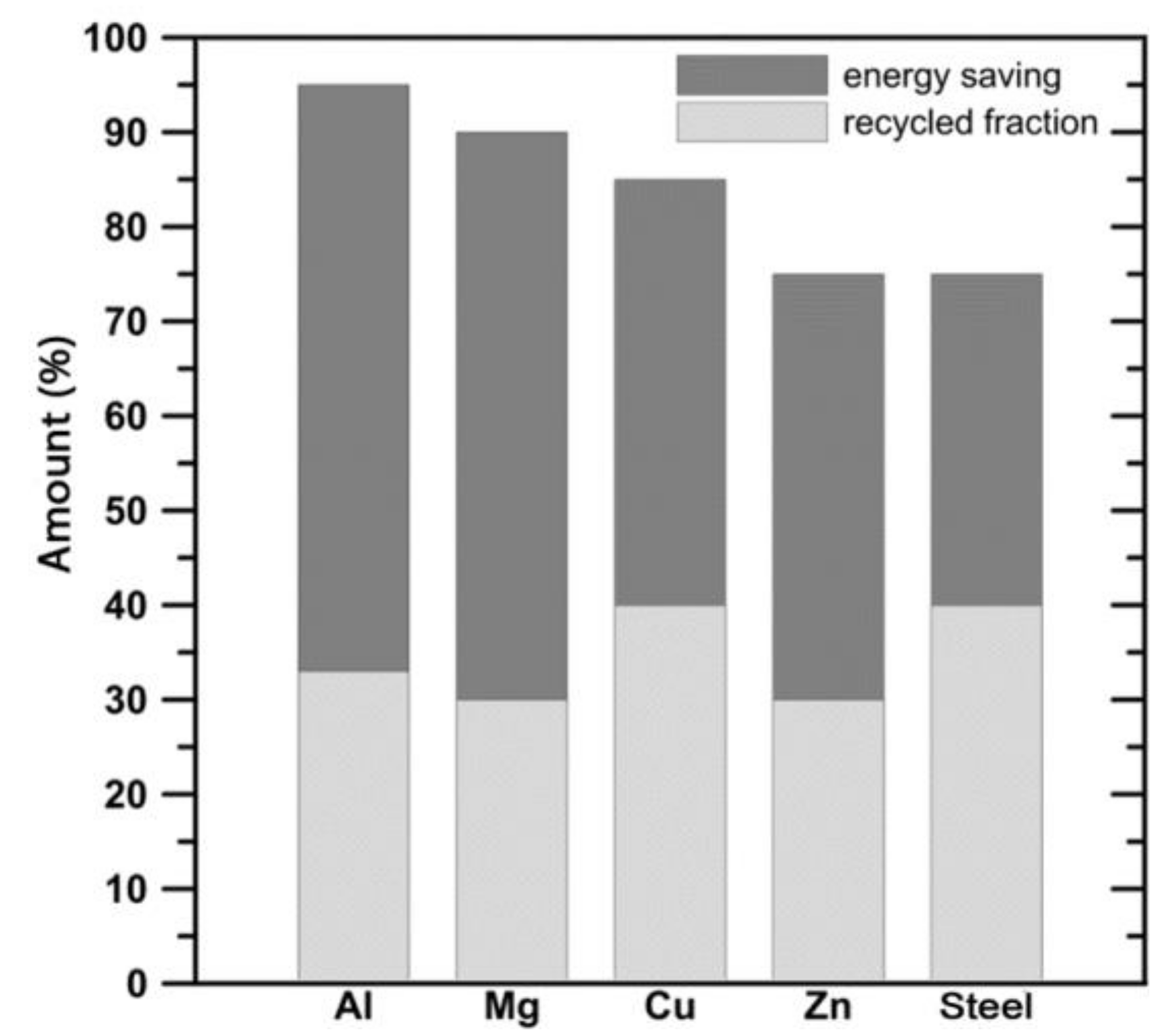
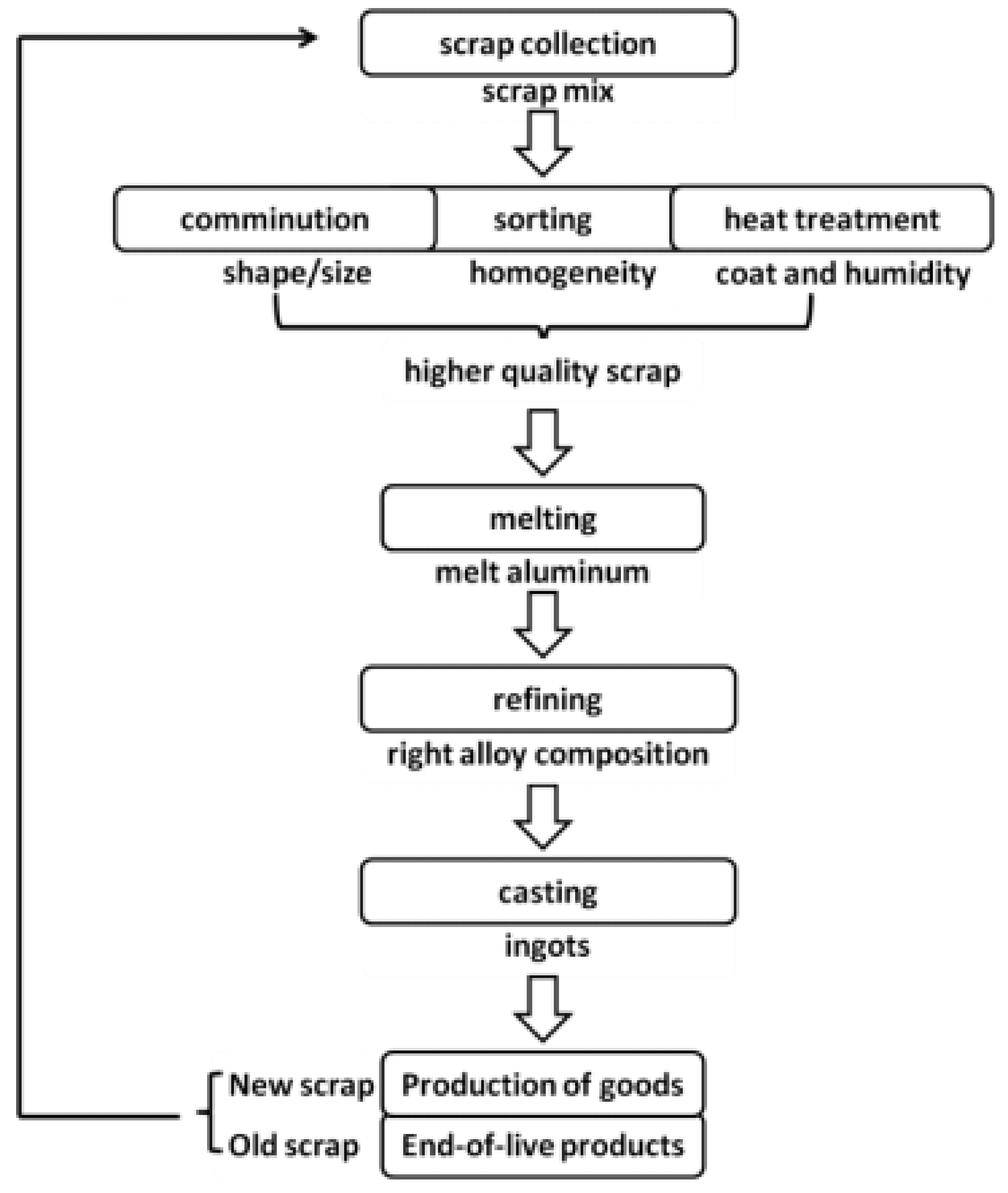
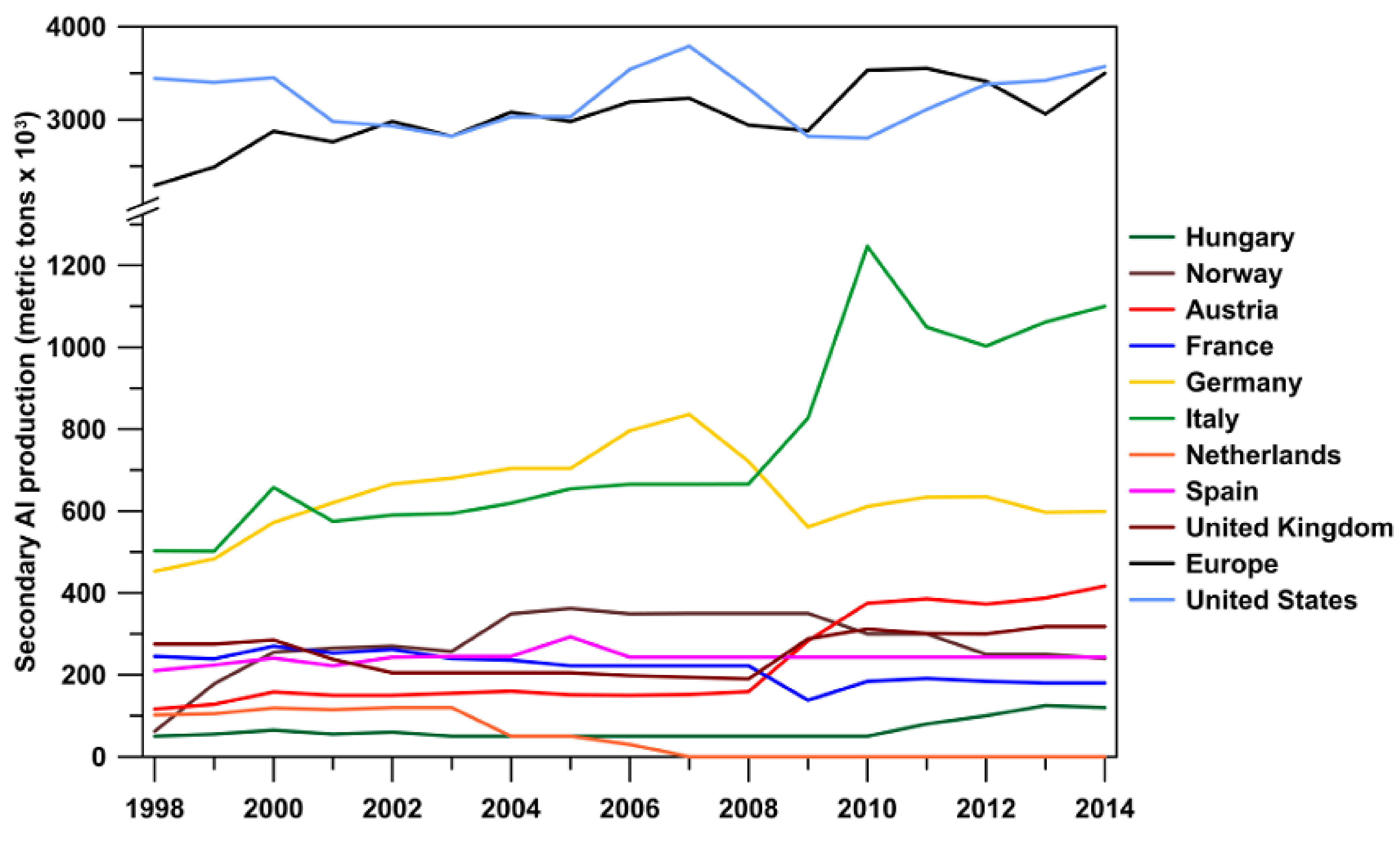
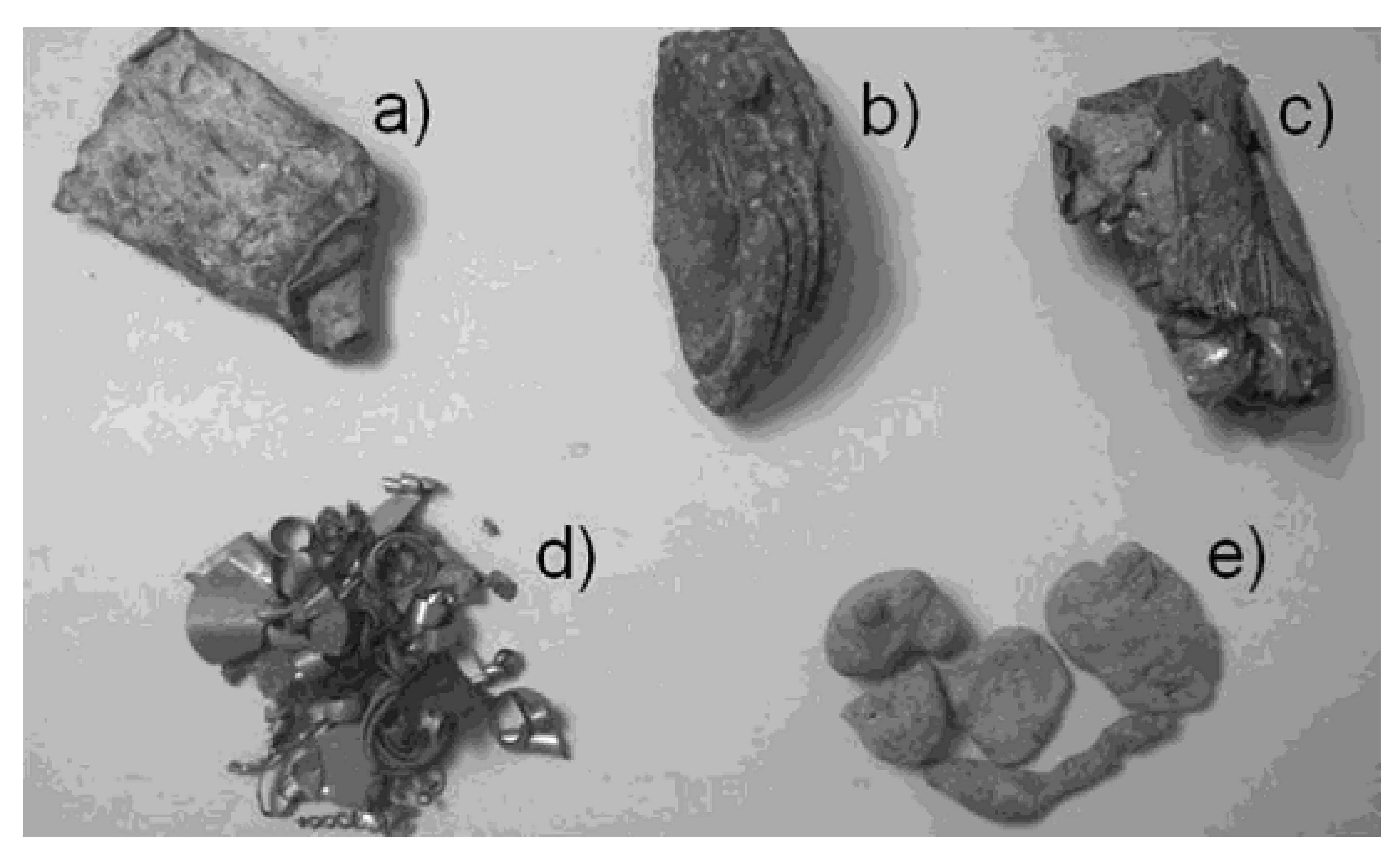
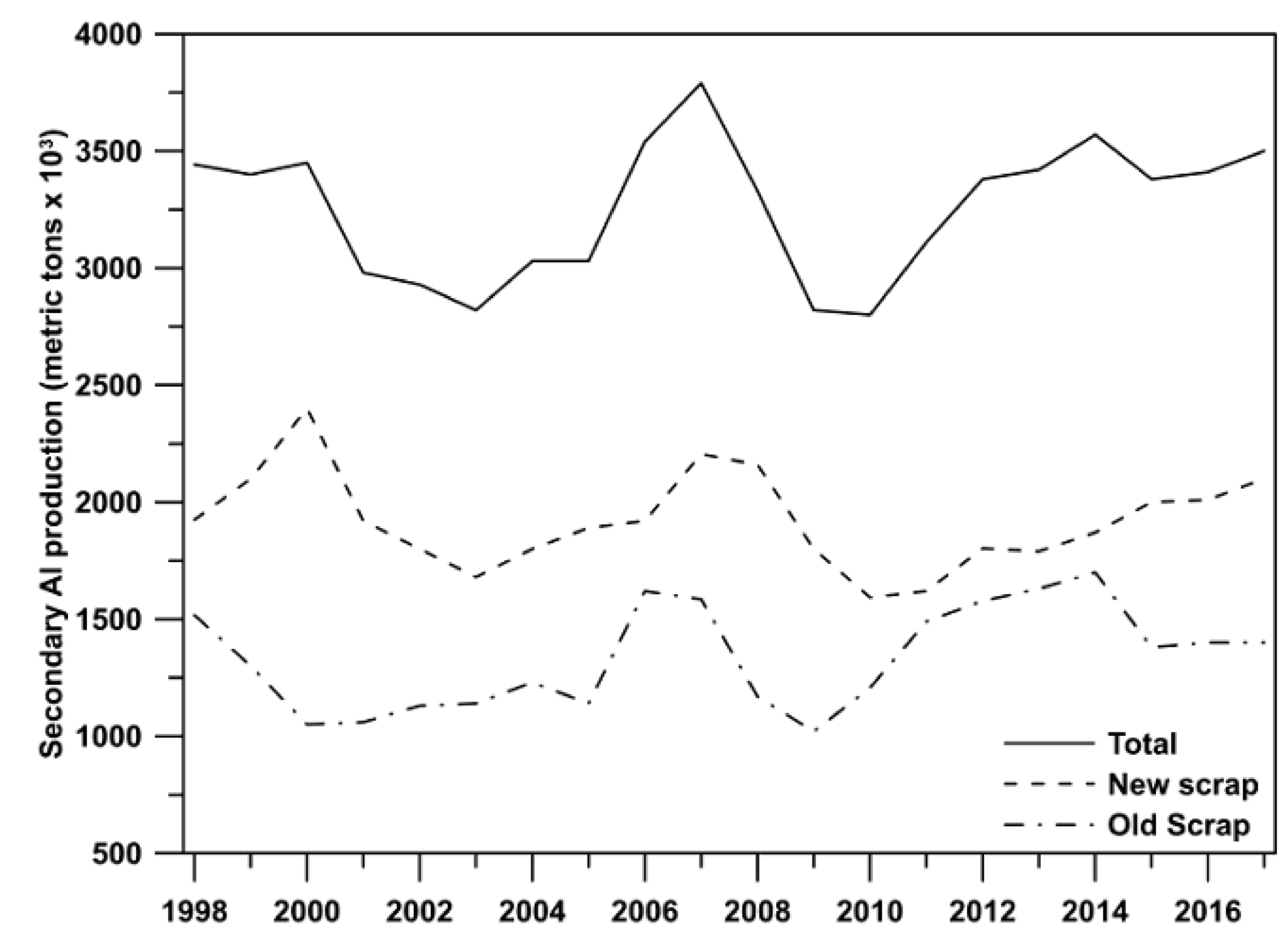
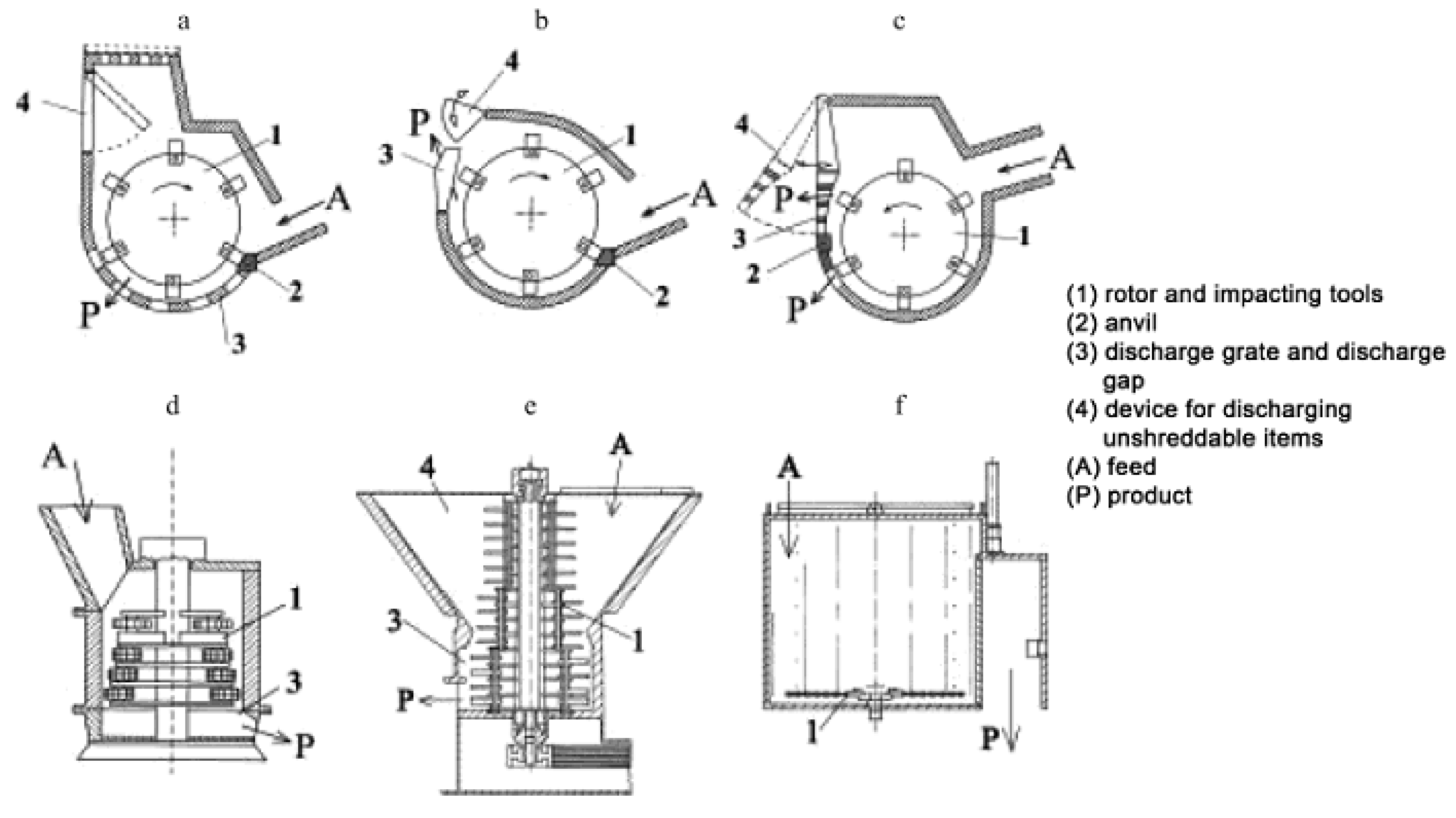
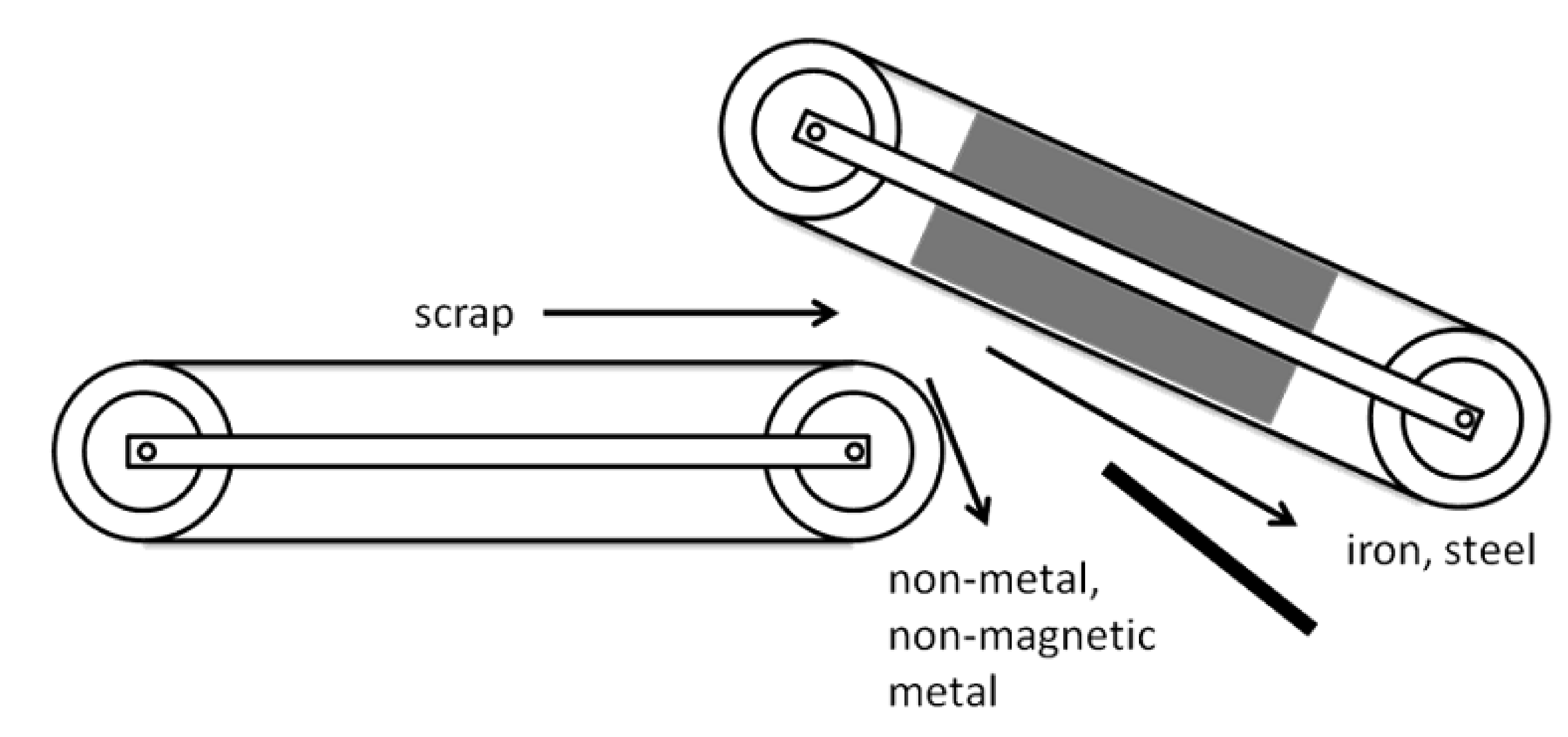
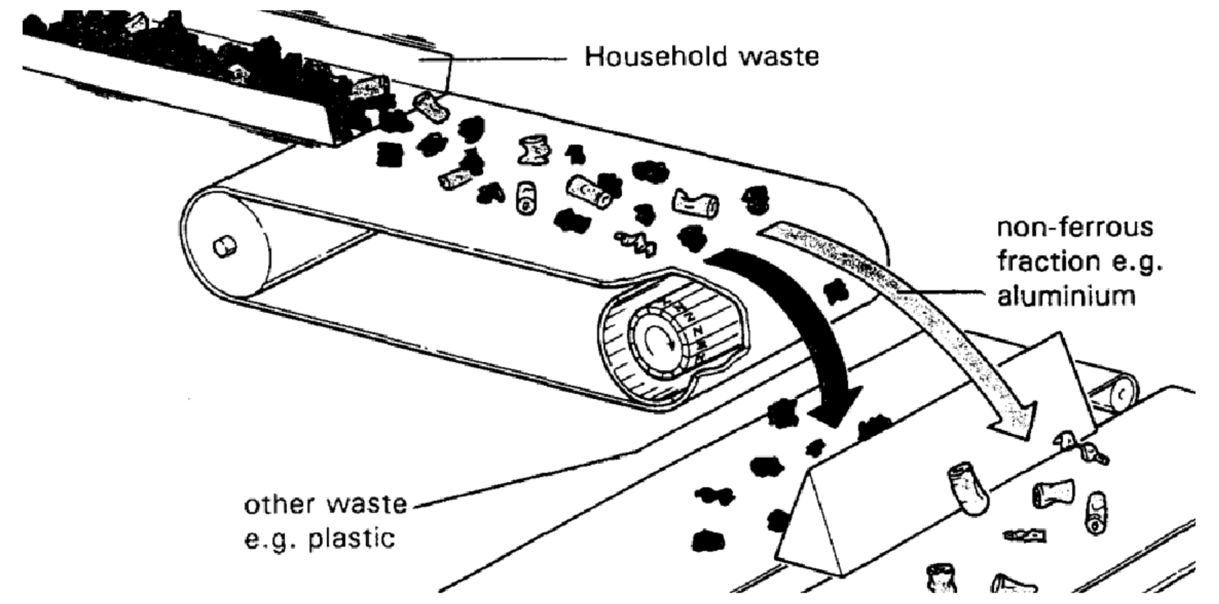
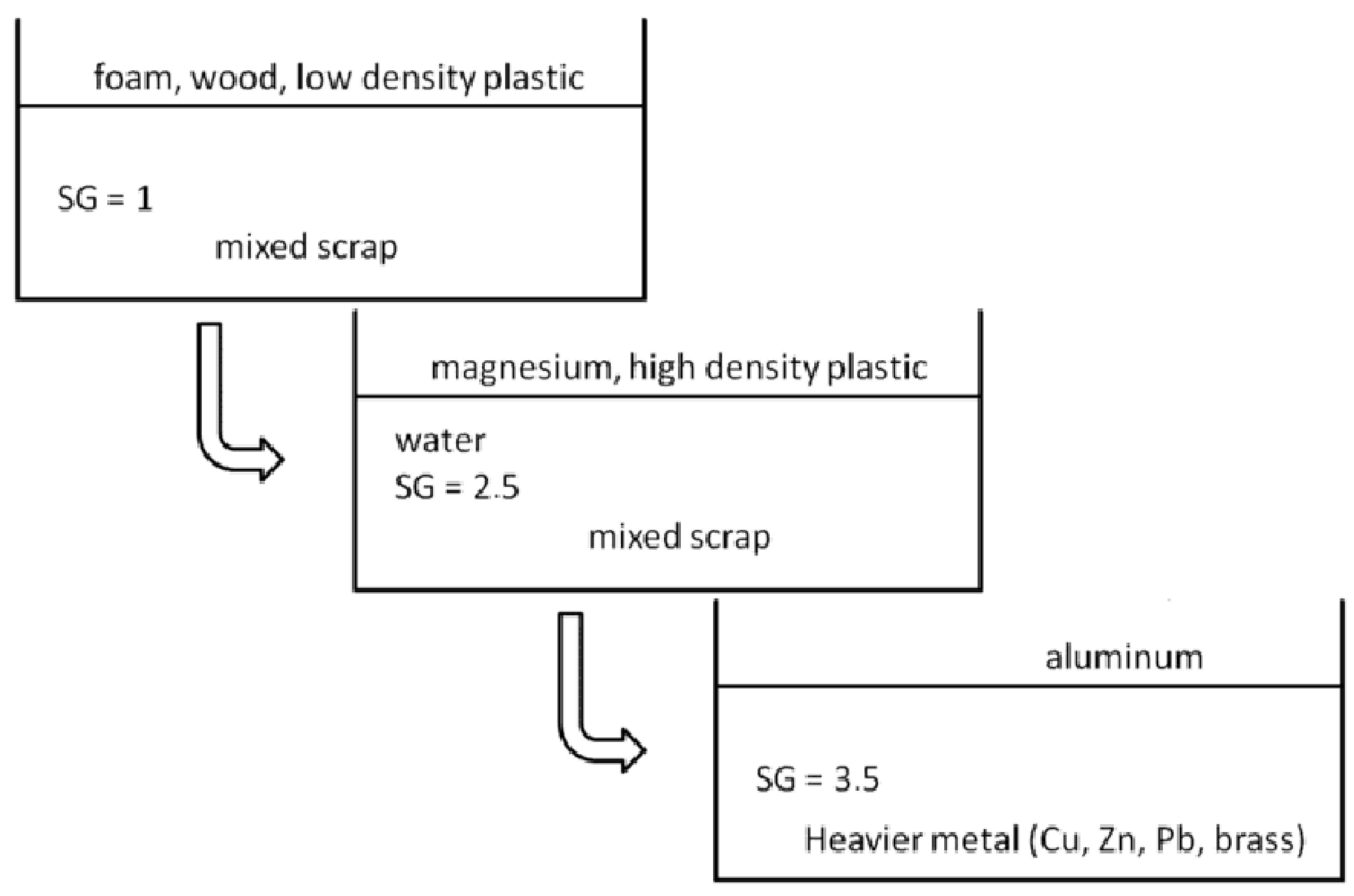
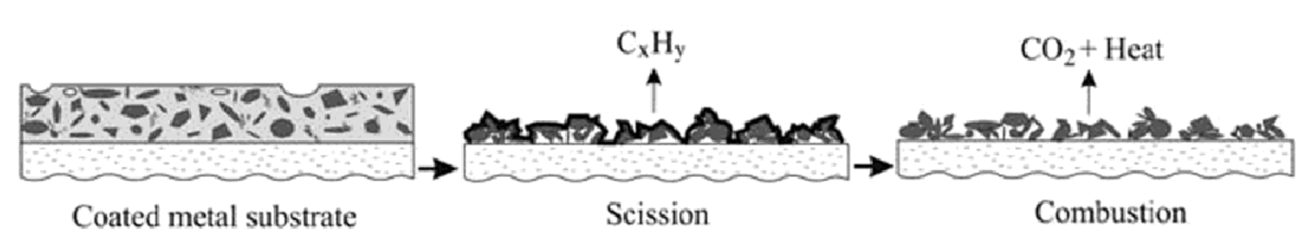
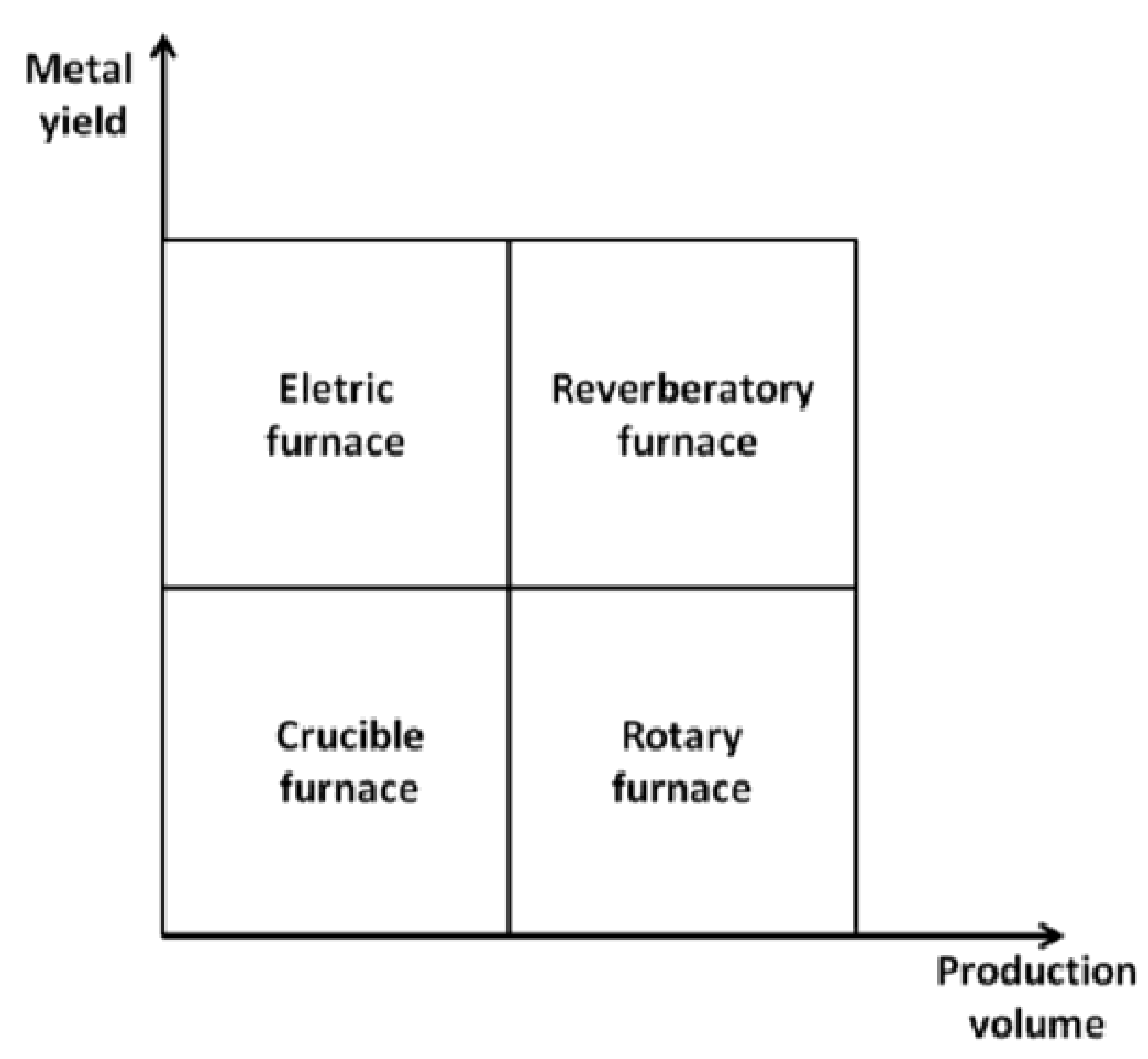
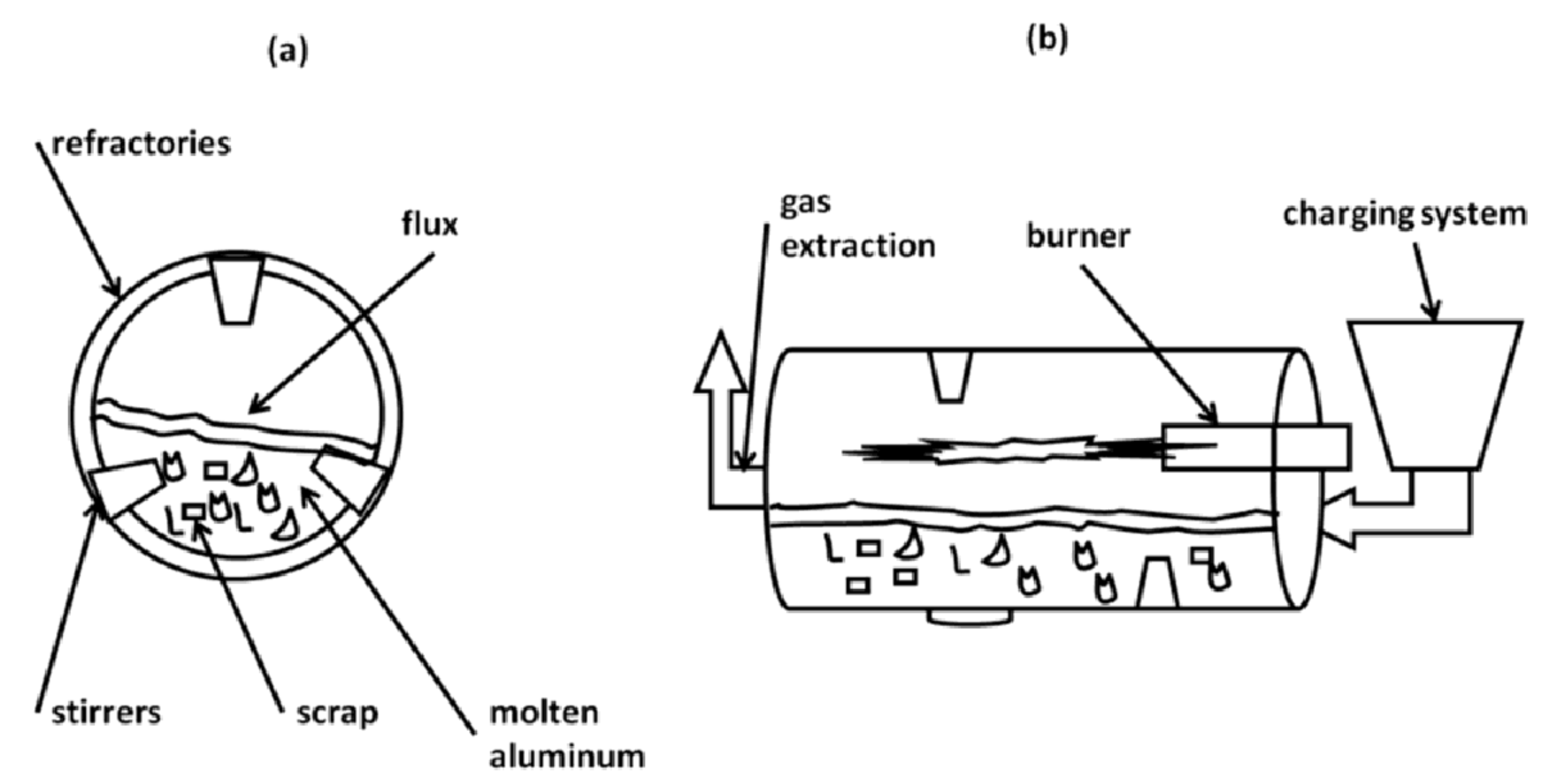
Table 1.
Classification of Al scrap showing the metal yields (lower limit and average value), the average amounts of undesired materials (oxides and foreign materials) and the cost. Data are read and elaborated from the different parts of EN 13920 standard [23].
Table 1.
Classification of Al scrap showing the metal yields (lower limit and average value), the average amounts of undesired materials (oxides and foreign materials) and the cost. Data are read and elaborated from the different parts of EN 13920 standard [23].
| EN 13920 Part No. | Scrap | Metal Yield Lower Limit (%) | Metal Yield Avg. Value (%) | Oxides (%) | Foreign Material (%) | Cost [24] * (€/ton) |
|---|---|---|---|---|---|---|
| 2 | unalloyed aluminum | 0.95 | - | - | - | 1232–1332 |
| 3 | wire and cable | ≥0.95 | 97.7 | 1.3 | 0.5 | 1182–1282 |
| 4 | single wrought alloy | ≥0.95 | 97.2 | 1.8 | 1.8 | 1272–1377 |
| 5 | two or more wrought alloys—same family | ≥0.88 | 97.2 | 1.0 | 2.0 | 1172–1222 |
| 6 | two or more wrought alloys | ≥0.88 | 94.0 | 0.8 | 5.2 | - |
| 7 | Casting | ≥0.9 | 83.4 | 6.2 | 10.4 | - |
| 8 | Shredded (not separated) | ≥0.9 | - | - | - | - |
| 9 | shredded (separated) | ≥0.9 | 84.5 | 5.4 | 10.1 | - |
| 10 | used beverage cans | ≥0.88 | 94.0 | 0.8 | 5.2 | 770–820 |
| 11 | Al-Cu radiators | - | - | - | - | 2247–2297 |
| 12 | Turnings single alloy | ≥0.9 | 95.3 | 3.7 | 1.0 | 1192–1257 |
| 13 | mixed turnings | ≥0.9 | 84.0 | 3.3 | 12.8 | 1157–1207 |
| 14 | coated packaging | ≥0.28 | 71.5 | 3.8 | 24.7 | - |
| 15 | de-coated packaging | ≥0.8 | 86.1 | 12.9 | 1 | - |
| 16 | dross | ≥0.3 | 55.7 | 44.3 | - | 158–338 |
* Available data are referred to market quotation on October 2017.
Table 2.
Classification of consolidated and innovative sorting methods showing the physical parameter and the desired separation; the developed technologies are also reported for each method.
Table 2.
Classification of consolidated and innovative sorting methods showing the physical parameter and the desired separation; the developed technologies are also reported for each method.
| Method | Separator Type | Physical Parameter | Desired Separation | Technology |
|---|---|---|---|---|
| Consolidated methods | magnetic separator | magnetic susceptibility | ferrous fraction, nickel-based alloy | magnetic drum, overhead belt magnet |
| air separator | mass | low density as paper, foam plastic | vertical zig-zag, air table, elutriator, air knives | |
| eddy current | conductivity | non-metal, and metal types | eddy current system, electromagnetic system | |
| dense media | density | non-metal and metal types | soak float, wet jig | |
| hand sorting | aspect | metal types and wrought-casting alloys | manual operation | |
| thermal | melting point | wrought-casting alloys | hot crush | |
| Innovative methods | elemental composition | vapor phase, plasma, x-ray energy, γ-ray energy | alloy type | LIBS, XRF, PGNAA * |
| image analysis | color and shape | alloy type | color, etch, 3D shape | |
| transmission | atomic number | alloy type | XRT * |
* XRF: X-ray fluorescence, LIBS: laser-induced breakdown spectroscopy, PGNAA: prompt gamma neutron, activation analysis, XRT: X-ray transmission.
Table 3.
Densities of aluminum and contaminant materials [39].
Table 3.
Densities of aluminum and contaminant materials [39].
| Material | Density (kg/dm3) |
|---|---|
| Aluminum | 2.6–2.9 |
| Lead | 10.7–11.3 |
| Copper | 7.5–9.0 |
| Stainless steels | 7.5–7.7 |
| Brass and bronze | 5.2–7.2 |
| Zinc | 5.2–7.2 |
| Magnesium | 1.7–1.9 |
| Polyvinyl chloride | 1.4 |
| Polystyrene | 1.0–1.1 |
| Polypropylene | 0.9 |
| Rubber | 0.8–0.9 |
| Wood | 0.4–0.8 |
| Polymeric foam | 0.01–0.6 |
Table 4.
Hazardous properties of aluminum salt slag according to the European waste catalogue and hazardous waste list. Data elaborated from [87].
Table 4.
Hazardous properties of aluminum salt slag according to the European waste catalogue and hazardous waste list. Data elaborated from [87].
| Code | Title | Meaning |
|---|---|---|
| H3-A | Highly flammable | substances and preparations which, in contact with water or damp air, evolve highly flammable gases in dangerous quantities |
| H4 | Irritant | non-corrosive substances or preparations which through immediate prolonged or repeated contact with the skin or mucous membrane can cause inflammation |
| H5 | Harm-full | substances and preparations which, if they are inhaled or ingested or if they penetrate the skin, involve limited health risk |
| H13 | Leachable | substances and preparations capable by any means, after disposal, of yielding another substance |
© 2018 by the authors. Licensee MDPI, Basel, Switzerland. This article is an open access article distributed under the terms and conditions of the Creative Commons Attribution (CC BY) license (http://creativecommons.org/licenses/by/4.0/).
Share and Cite
MDPI and ACS Style
Capuzzi, S.; Timelli, G. Preparation and Melting of Scrap in Aluminum Recycling: A Review. Metals 2018, 8, 249. https://doi.org/10.3390/met8040249
AMA Style
Capuzzi S, Timelli G. Preparation and Melting of Scrap in Aluminum Recycling: A Review. Metals. 2018; 8(4):249. https://doi.org/10.3390/met8040249
Chicago/Turabian StyleCapuzzi, Stefano, and Giulio Timelli. 2018. "Preparation and Melting of Scrap in Aluminum Recycling: A Review" Metals 8, no. 4: 249. https://doi.org/10.3390/met8040249
Note that from the first issue of 2016, this journal uses article numbers instead of page numbers. See further details here.