
Inverse Thermal Analysis as a Tool for Optimizing Concentrated Solar Energy Elaboration of Wear Resistant Surface Layers

 , and
, and 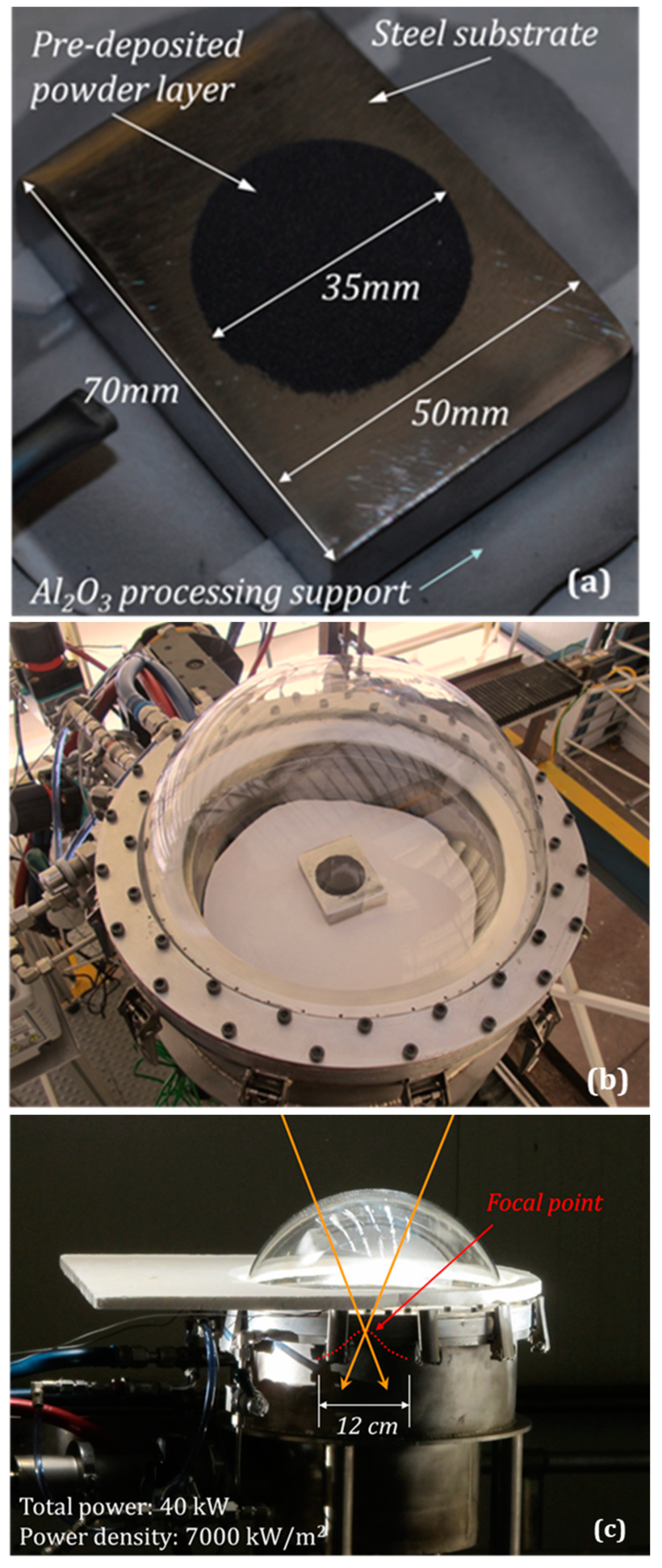
Abstract
:1. Introduction
2. Materials and Methods
3. Experimental Findings and Physical Model
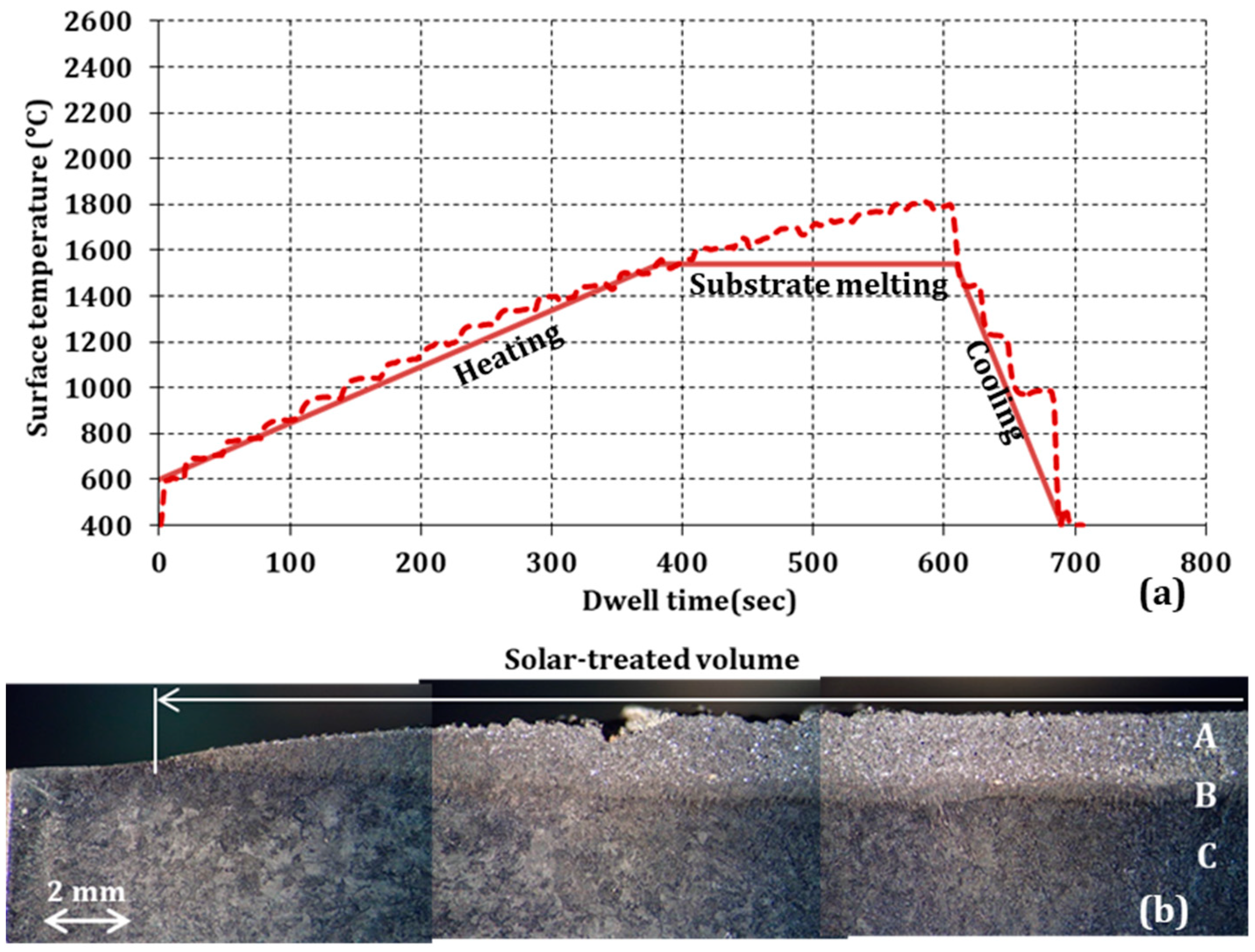
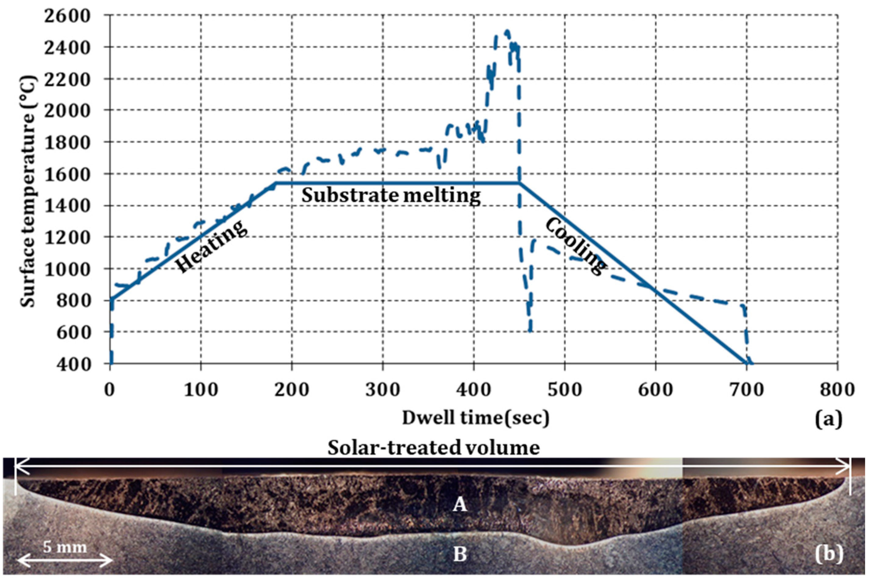
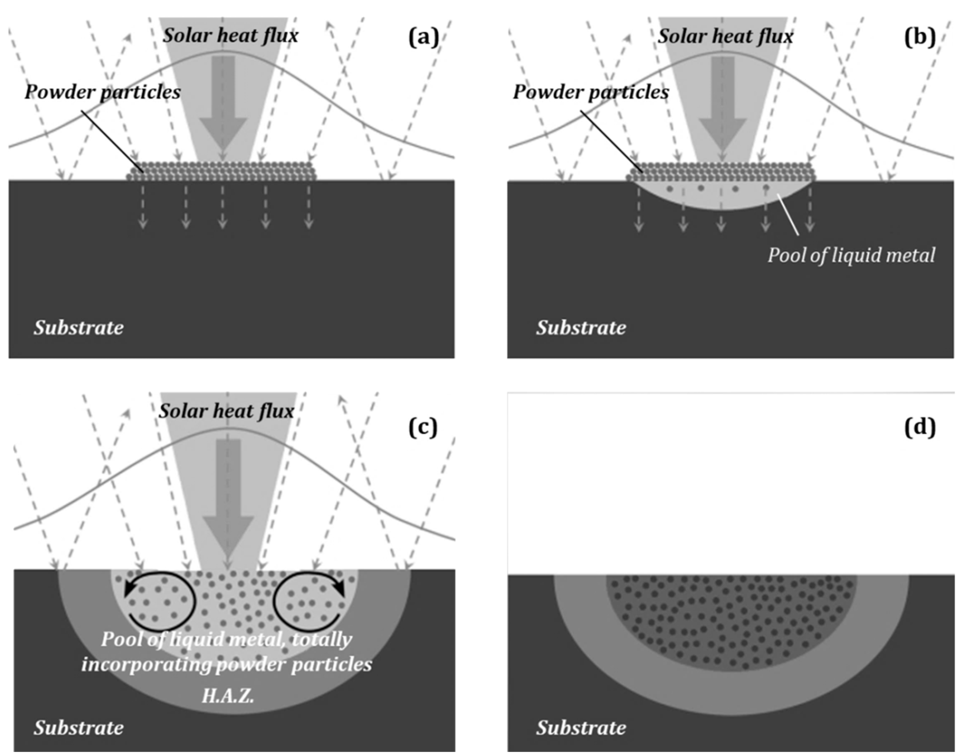
- During heating at surface temperature below the melting temperature of the substrate (Tmax: 1540 °C), the concentrated solar energy is absorbed only by the area covered by the black-colored ceramic particles, while it is reflected by the noncovered polished surface of the base metal (Figure 6a).
- During heating at surface temperature above the melting temperature of the substrate, the solar energy absorbed results in progressive melting of the underlying metal and immersion of the pre-deposited powder in the melting pool (Figure 6b).
- Lasting the solar exposure of the workpiece, the depth of the melting pool increases and the circulation currents in the ferrous melt lead to the homogeneous distribution of the carbide particles in the liquid metal (Figure 6c). Depending on the nature of the incorporated carbides, they either remain non-attacked (TiC case), or are diluted in the molten steel (Cr3C2 case).
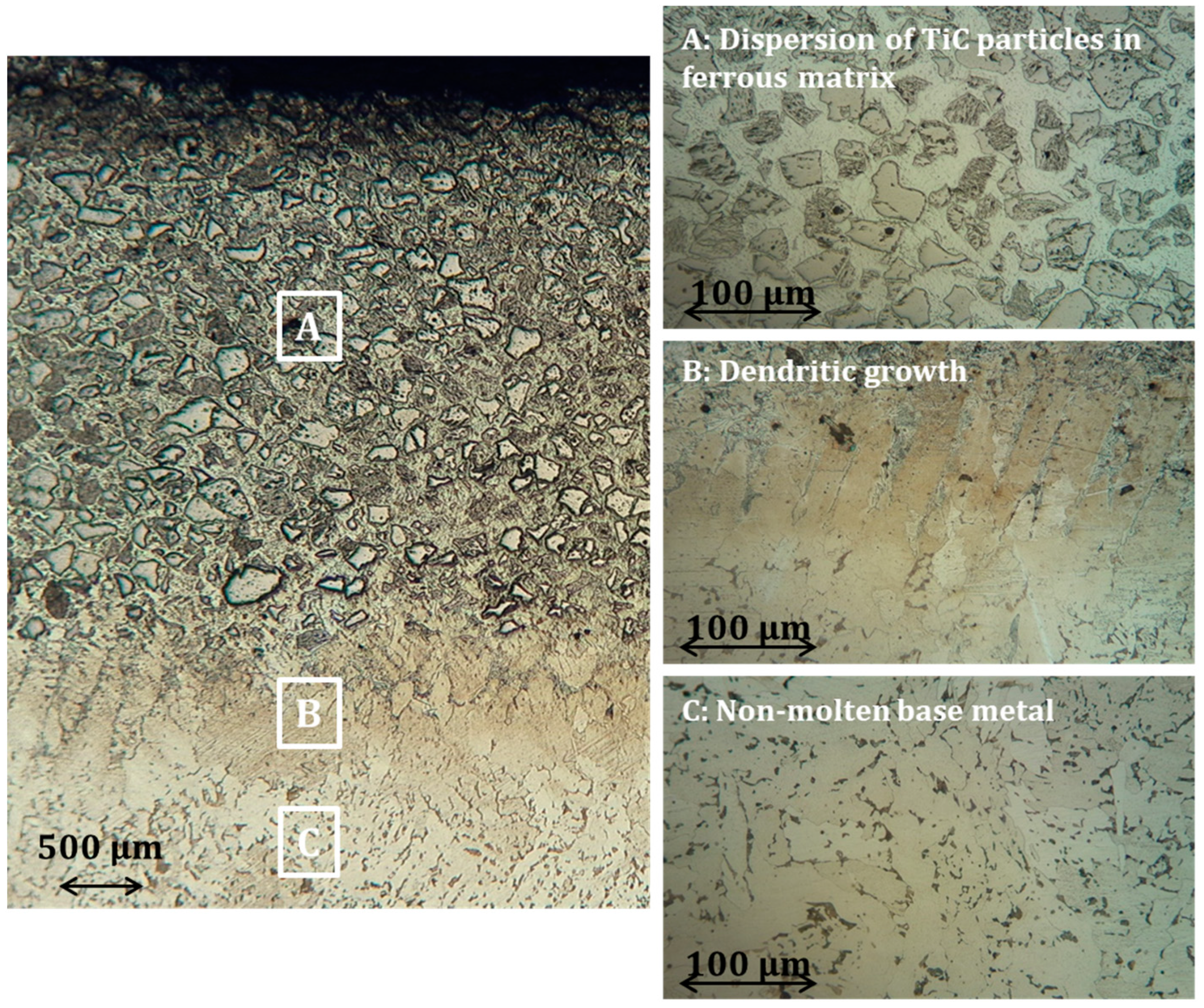
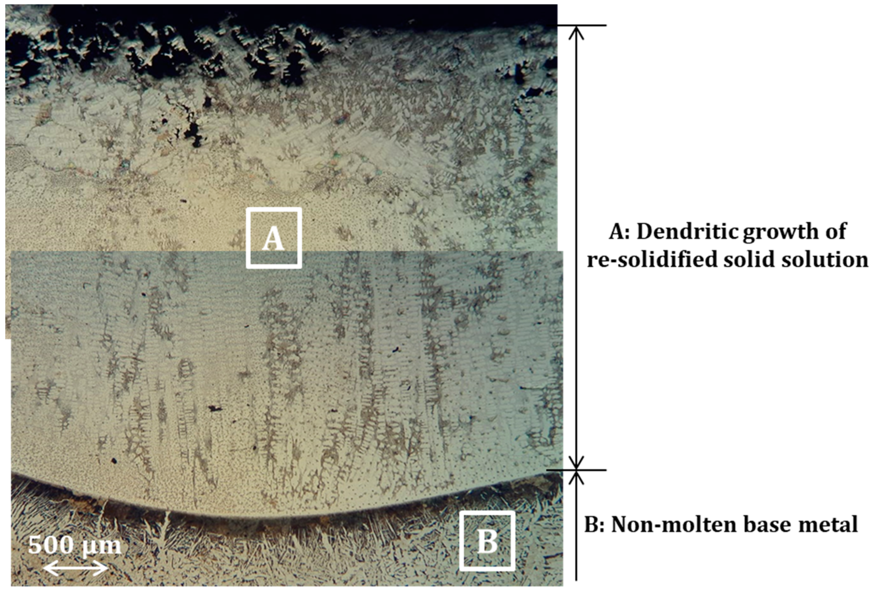
- During cooling to ambient temperature, the solidification of the melts follows the thermodynamic path imposed by their chemical composition, whilst solid state metallurgical transformations complete the final microstructure of the obtained solar-treated surface, as well as that of the heat-affected area, H.A.Z., (Figure 6d). In both material systems, the areas of dendritic growth (Figure 3 and Figure 5)—at the bottom of the re-solidified pool, in contact to the nonmolten base metal—are indicative of the solidification starting points and the heat dissipation directions.
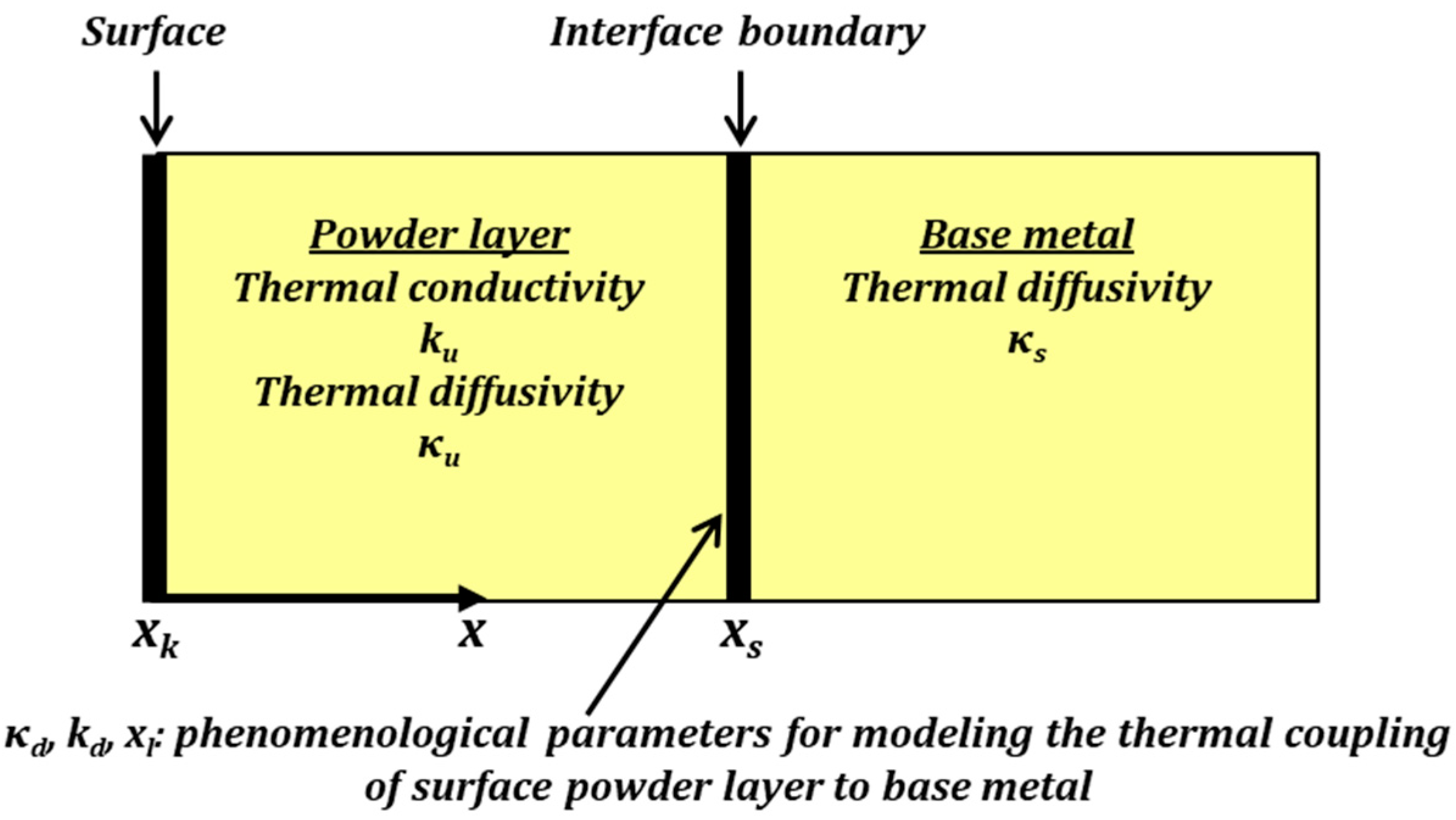
- nature of coupling between the surface-heating source and the workpiece that consists of a powder layer onto a metallic substrate. This coupling is not purely diffusive, but in principle, is a combination of Beer—Lambert-type volumetric energy deposition and advection-diffusion of heat;
- thermal contact properties at the pre-deposited powder layer-metallic substrate interface,
- complexity of the metallurgical transformations taking place between the powder layer and substrate materials;
- changes in volume and shape of the molten region that are produced by the dispersion of the powder particles in the solar-affected region of the substrate materials.
4. Inverse Thermal Analysis
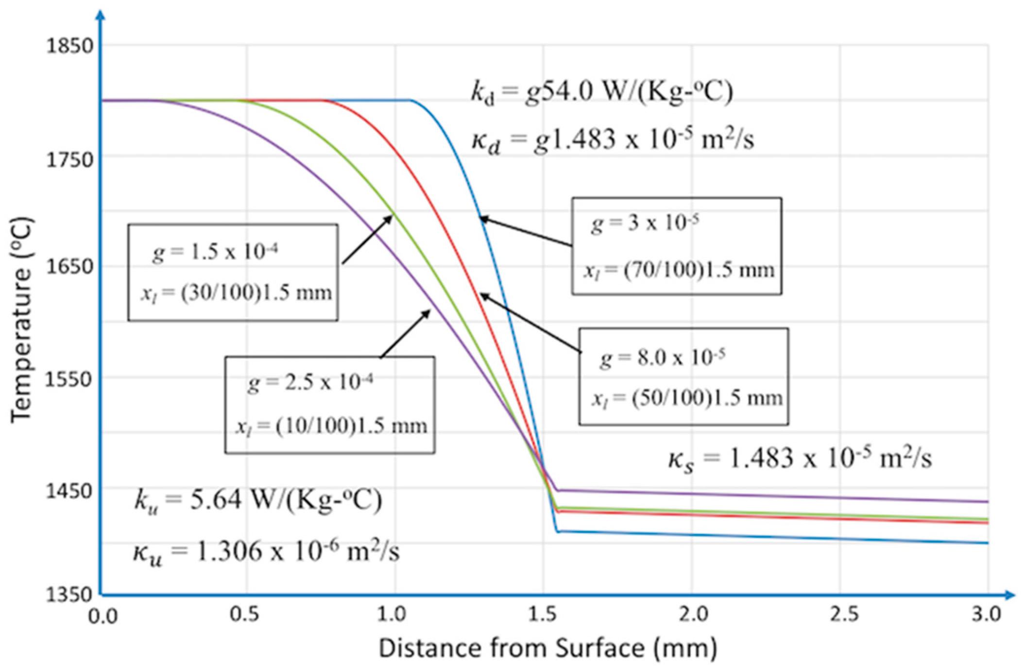
- Beer—Lambert-type volumetric energy-deposition and advection diffusion of heat;
- differentiation of the thermal properties of the surface layer-substrate at the contact interface;
- nonuniform mixing of layer and substrate materials;
- temporal changes of the volume and the exact shape of the molten pool.
5. Conclusions
Author Contributions
Funding
Institutional Review Board Statement
Informed Consent Statement
Data Availability Statement
Conflicts of Interest
References
- Pitts, J.R.; Tracy, E.; Shinton, Y.; Fields, C.L. Applications of solar energy to surface modification processes. Crit. Rev. Surf. Chem. 1993, 2, 247–269. [Google Scholar]
- Rodríguez, G.P.; de Damborenea, J.J.; Vázquez, A.J. Surface hardening of steel in a solar furnace. Surf. Coat. Technol. 1997, 92, 165–170. [Google Scholar] [CrossRef]
- Flamant, G.; Ferriere, A.; Laplaze, D.; Monty, C. Solar processing of materials: Opportunities and new frontiers. Sol. Energy 1999, 66, 117–132. [Google Scholar] [CrossRef]
- Rodríguez, G.P.; Herranz, G.; Romero, A. Solar gas nitriding of Ti6Al4V alloy. Appl. Surf. Sci. 2013, 283, 445–452. [Google Scholar] [CrossRef]
- Pantelis, D.I.; Psyllaki, P.; Sarafoglou, C. Surface alloying on cast iron using concentrated solar energy. Fonderie Fondeur Aujourd’hui 2002, 211, 23–33. [Google Scholar]
- Mourlas, A.; Psyllaki, P.; Pantelis, D. Anti-wear TiC-based surface layers using concentrated solar energy. Key Eng. Mater. 2016, 674, 296–301. [Google Scholar] [CrossRef]
- Mourlas, A.; Pavlidou, E.; Vourlias, G.; Rodríguez, J.; Psyllaki, P. Concentrated solar energy for in-situ elaboration of wear-resistant composite layers. Part I: TiC and chromium carbide surface enrichment of common steels. Surf. Coat. Technol. 2019, 377, 124882. [Google Scholar] [CrossRef]
- Mourlas, A.; Pavlidou, E.; Vourlias, G.; Rodríguez, J.; Psyllaki, P. Concentrated solar energy for in-situ elaboration of wear-resistant composite layers. Part II: Tungsten carbide surface enrichment of common steels. Surf. Coat. Technol. 2019, 375, 739–751. [Google Scholar] [CrossRef]
- Pantelis, D.I.; Griniari, A.; Sarafoglou, C. Surface alloying of pre-deposited molybdenum-based powder on 304L stainless steel using concentrated solar energy. Sol. Energy Mat. Sol. Cells 2005, 89, 1–11. [Google Scholar] [CrossRef]
- Fernández-González, D.; Ruiz-Bustinza, ĺ.; González-Gasca, C.; Piñuela-Noval, J.; Mochón-Castaños, J.; Sancho-Gorostiaga, J.; Verdeja, L.F. Concerntrated solar energy applications in materials science and metallurgy. Sol. Energy 2018, 170, 520–540. [Google Scholar] [CrossRef]
- International Energy Agency. Renewable Energy for Industry: From Green Energy to Green Materials and Fuels. 2017. Available online: https://www.iea.org/publications/freepublications/publication/ (accessed on 25 March 2023).
- Sánchez Bautista, C.; Rodríguez, G.P.; Ferriere, A. Numerical modelling of the solar cladding process. Surf. Coat. Technol. 2008, 202, 1594–1605. [Google Scholar] [CrossRef]
- Li, B.; Oliveira, F.A.C.; Rodríguez, J.; Fernandes, J.C.; Rosa, L.G. Numerical and experimental study on improving temperature uniformity of solar furnaces for materials processing. Sol. Energy 2015, 115, 95–108. [Google Scholar] [CrossRef]
- Romero, A.; García, I.; Arenas, M.A.; López, V.; Vázquez, A. High melting point materials welding by concentrated solar energy. Sol. Energy 2013, 95, 131–143. [Google Scholar] [CrossRef]
- Román, R.; Cañadas, I.; Rodríguez, J.; Hernández, M.T.; González, M. Solar sintering of alumina ceramics: Microstructural development. Sol. Energy 2008, 82, 893–902. [Google Scholar] [CrossRef]
- Gutiérrez-López, J.; Levenfeld, B.; Várez, A.; Pastor, J.Y.; Cañadas, I.; Rodríguez, J. Study of the densification, mechanical and magnetic properties of Ni-Zn ferrites sintered in a solar furnace. Ceram. Int. 2015, 41, 6534–6541. [Google Scholar] [CrossRef]
- Herranz, G.; Romero, A.; DeCastro, V.; Rodríguez, G.P. Processing of AISI M2 high speed steel Reinforced with vanadium carbide by solar sintering. Mater. Des. 2014, 54, 934–946. [Google Scholar] [CrossRef]
- Cambronero, L.E.G.; Cañadas, I.; Martínez, D.; Ruiz-Román, J.M. Foaming of aluminium-silicon alloy using concentrated solar energy. Sol. Energy 2010, 84, 879–889. [Google Scholar] [CrossRef]
- Ozisik, M.N.; Orlande, H.R.B. Inverse Heat Transfer, Fundamentals and Applications; Taylor & Francis: New York, NY, USA, 2000. [Google Scholar]
- Kurpisz, K.; Nowak, A.J. Inverse Thermal Problems—Computational Engineering; WIT Press: Boston, MA, USA, 1995. [Google Scholar]
- Alifanov, O.M. Inverse Heat Transfer Problems; Springer: Berlin/Heidelberg, Germany, 1994. [Google Scholar]
- Beck, J.V.; Blackwell, B.; St. Clair, C.R., Jr. Inverse Heat Conduction: Ill-Posed Problems; John Wiley & Sons Inc.: New York, NY, USA, 1985. [Google Scholar]
- Beck, J.V. Inverse Problems in Heat Transfer with Application to Solidification and Welding. In Proceedings of the 5th Conference on Modeling of Casting, Welding and Advanced Solidification Processes, Davos, Switzerland, 16–21 September 1990. [Google Scholar]
- Beck, J.V. Inverse Problems in Heat Transfer. In Mathematics of Heat Transfer; Tupholme, G.E., Wood, A.S., Eds.; Oxford University Press: New York, NY, USA, 1998; pp. 13–24. [Google Scholar]
- Lambrakos, S.G. Parametric Modeling of welding processes using numerical-analytical basis functions and equivalent source distributions. J. Mater. Eng. Perform. 2016, 25, 1360–1375. [Google Scholar] [CrossRef]
- Prosgolitis, C.G.; Lambrakos, S.G.; Zervaki, A. Phase-Field Modeling of Nugget Zone for a AZ31-Mg-Alloy Friction Stir Weld. J. Mater. Eng. Perform. 2018, 27, 5102–5113. [Google Scholar] [CrossRef]
- Carslaw, H.S.; Jaegar, J.C. Conduction of Heat in Solids, 2nd ed.; Oxford University Press: New York, NY, USA, 1986; p. 374. [Google Scholar]
- Zervaki, A.D.; Mourlas, A.G.; Psyllaki, P.P.; Lambrakos, S.G. Parametric Model of Concentrated Solar Energy Surface Processing. In Proceedings of the Advances in Welding & Additive Manufacturing Research Conference 2022, Miami, FL, USA, 13–16 June 2022. [Google Scholar]
- Rodríguez, J.; Cañadas, I.; Zarza, E. New PSA high concentration solar furnace SF40. AIP Conf. Proc. 2016, 1734, 070028. [Google Scholar]
- Shackelford, J.F.; Han, Y.-H.; Kim, S.; Kwon, S.-H. CRC Materials Science and Engineering Handbook, 4th ed.; Taylor & Francis: Boca Raton, FL, USA, 2015; pp. 50, 263, 279. [Google Scholar]
- Pankratz, L.B. Thermodynamic Properties of Carbides, Nitrides, and Other Selected Substances; US Department of the Interior, Bureau of Mines: Washington, DC, USA, 1994; 696, p. 223.
- Desorbo, W. Heat Capacity of Chromium Carbide (Cr3C2) from 13 to 300 °K. J. Am. Chem. Soc. 1953, 75, 1825–1827. [Google Scholar] [CrossRef]
- Oriani, R.A.; Murphy, W.K. The Heat Capacity of Chromium Carbide (Cr3C2). J. Am. Chem. Soc. 1954, 76, 343–345. [Google Scholar] [CrossRef]
- Kelley, K.K.; Boericke, F.S.; Moore, G.E.; Huffman, E.H.; Bangert, W.M. Thermodynamic Properties of the Carbides of Chromium; US Department of the Interior, Bureau of Mines: Washington, DC, USA, 1944; 662, pp. 7–15.
- Abolhasani, D.; Hossein Seyedkashi, S.M.; Kang, N.; Kim, Y.J.; Woo, Y.Y.; Moon, Y.H. Analysis of Melt-Pool Behaviors during Selective Laser Melting of AISI 304 Stainless-Steel Composites. Metals 2019, 9, 876. [Google Scholar] [CrossRef]
- Tabaie, S.; Rézaï-Aria, F.; Jahazi, M. Microstructure Evolution of Selective Laser Melted Inconel 718: Influence of High Heating Rates. Metals 2020, 10, 587. [Google Scholar] [CrossRef]


Disclaimer/Publisher’s Note: The statements, opinions and data contained in all publications are solely those of the individual author(s) and contributor(s) and not of MDPI and/or the editor(s). MDPI and/or the editor(s) disclaim responsibility for any injury to people or property resulting from any ideas, methods, instructions or products referred to in the content. |
© 2023 by the authors. Licensee MDPI, Basel, Switzerland. This article is an open access article distributed under the terms and conditions of the Creative Commons Attribution (CC BY) license (https://creativecommons.org/licenses/by/4.0/).
Share and Cite
Zervaki, A.D.; Lambrakos, S.G.; Mourlas, A.G.; Papantoniou, I.G.; Rodríguez, J.; Psyllaki, P.P. Inverse Thermal Analysis as a Tool for Optimizing Concentrated Solar Energy Elaboration of Wear Resistant Surface Layers. Metals 2023, 13, 942. https://doi.org/10.3390/met13050942
Zervaki AD, Lambrakos SG, Mourlas AG, Papantoniou IG, Rodríguez J, Psyllaki PP. Inverse Thermal Analysis as a Tool for Optimizing Concentrated Solar Energy Elaboration of Wear Resistant Surface Layers. Metals. 2023; 13(5):942. https://doi.org/10.3390/met13050942
Chicago/Turabian StyleZervaki, Anna D., Samuel G. Lambrakos, Athanasios G. Mourlas, Ioannis G. Papantoniou, José Rodríguez, and Pandora P. Psyllaki. 2023. "Inverse Thermal Analysis as a Tool for Optimizing Concentrated Solar Energy Elaboration of Wear Resistant Surface Layers" Metals 13, no. 5: 942. https://doi.org/10.3390/met13050942