
On the Influence of Binder Material in PCBN Cutting Tools for Turning Operations of Inconel 718

 , , , and
Abstract
:1. Introduction
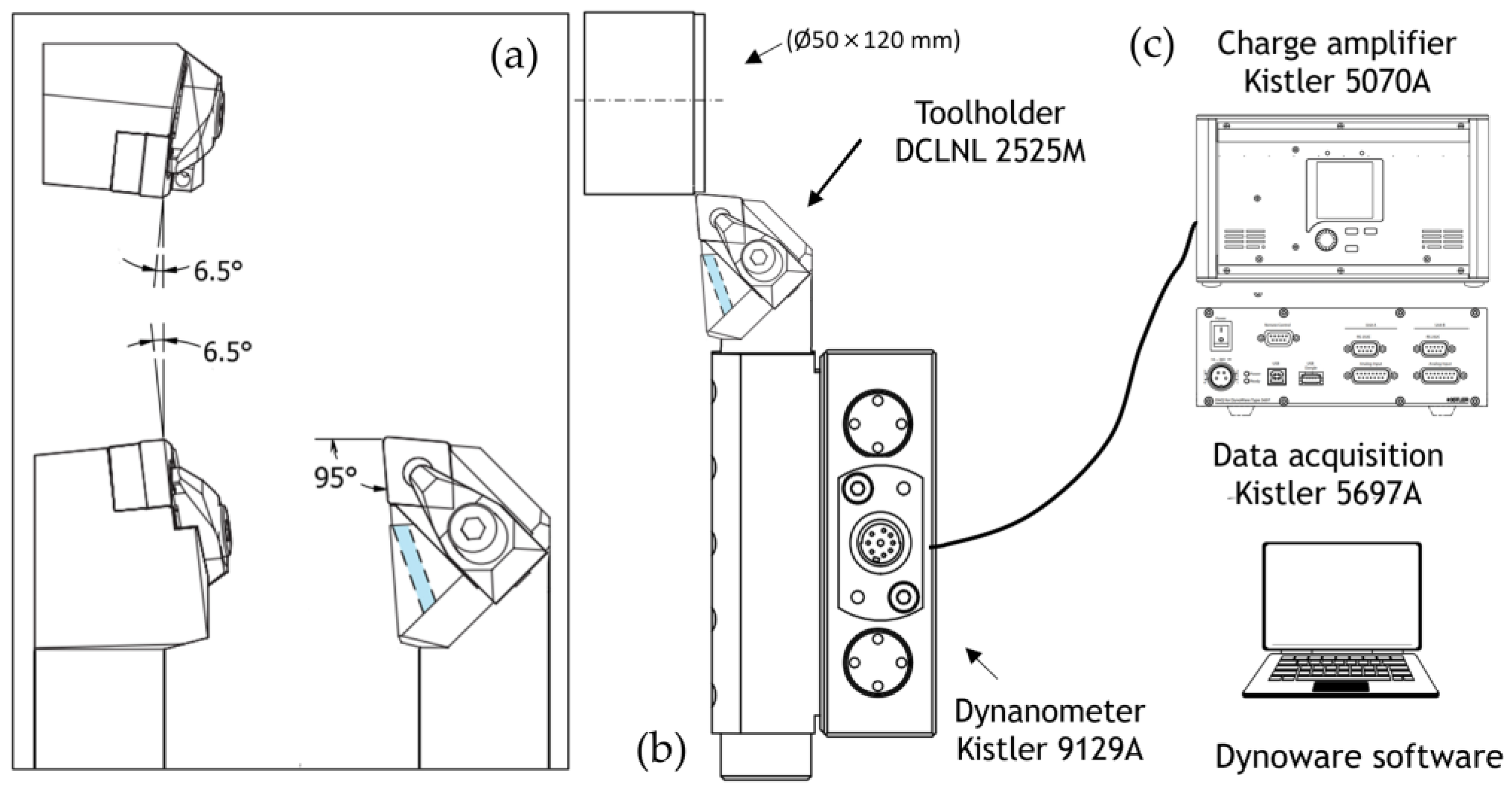
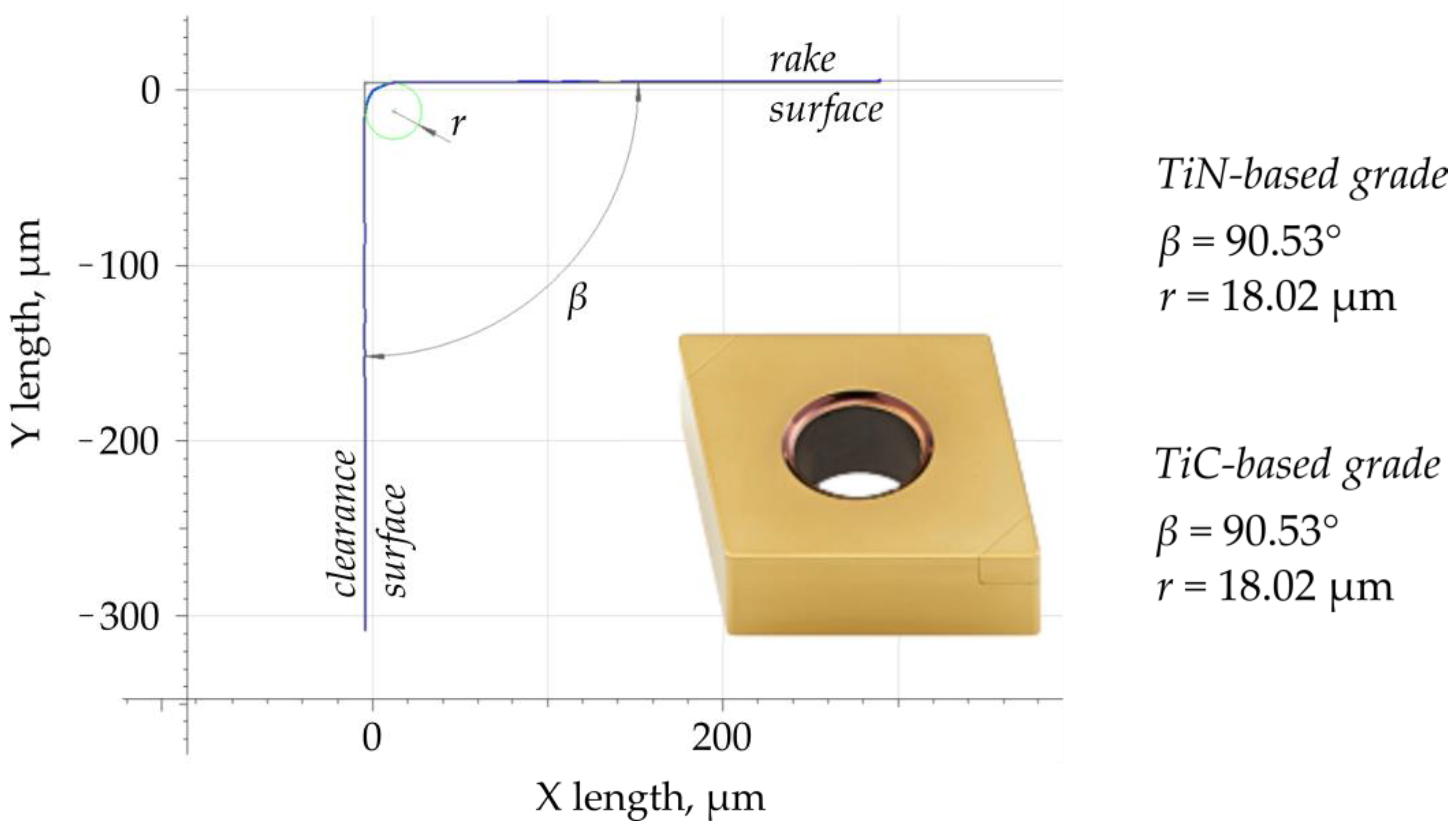
2. Materials and Methods
3. Results and Discussion
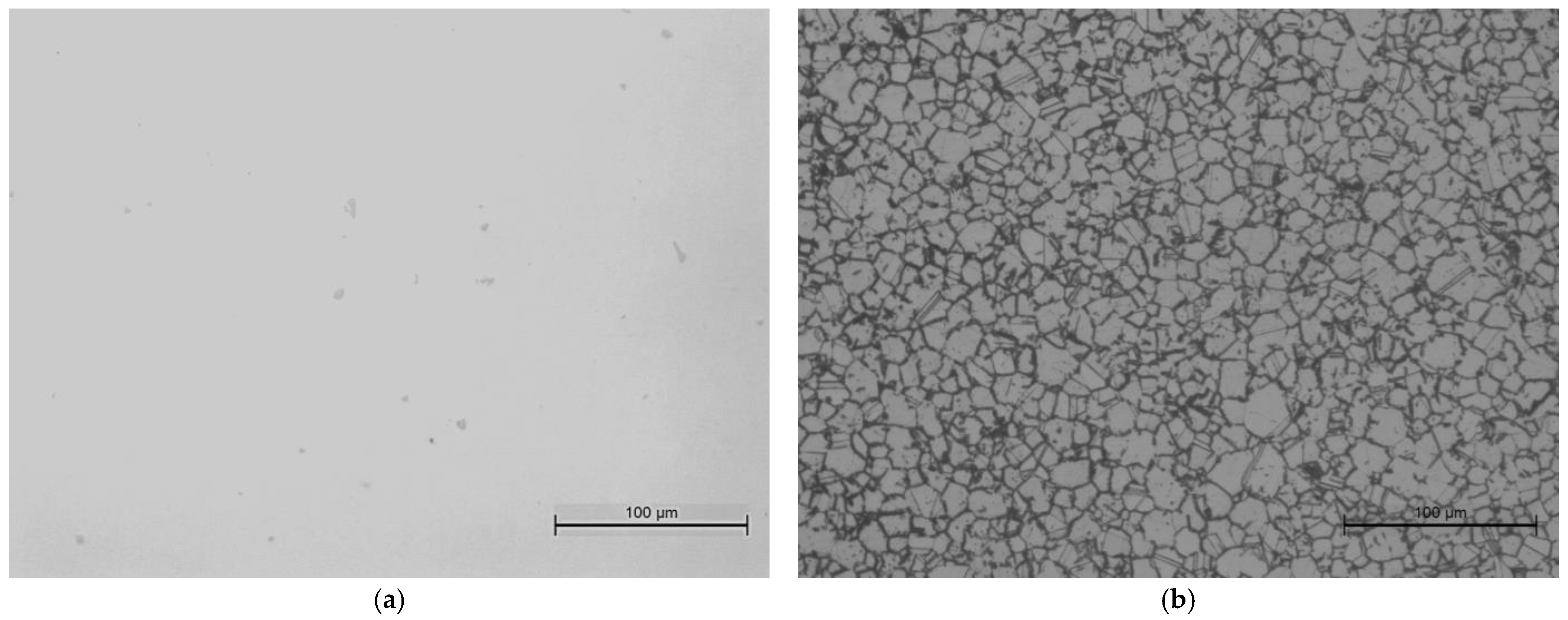
3.1. Workpiece Material Inspection Analysis
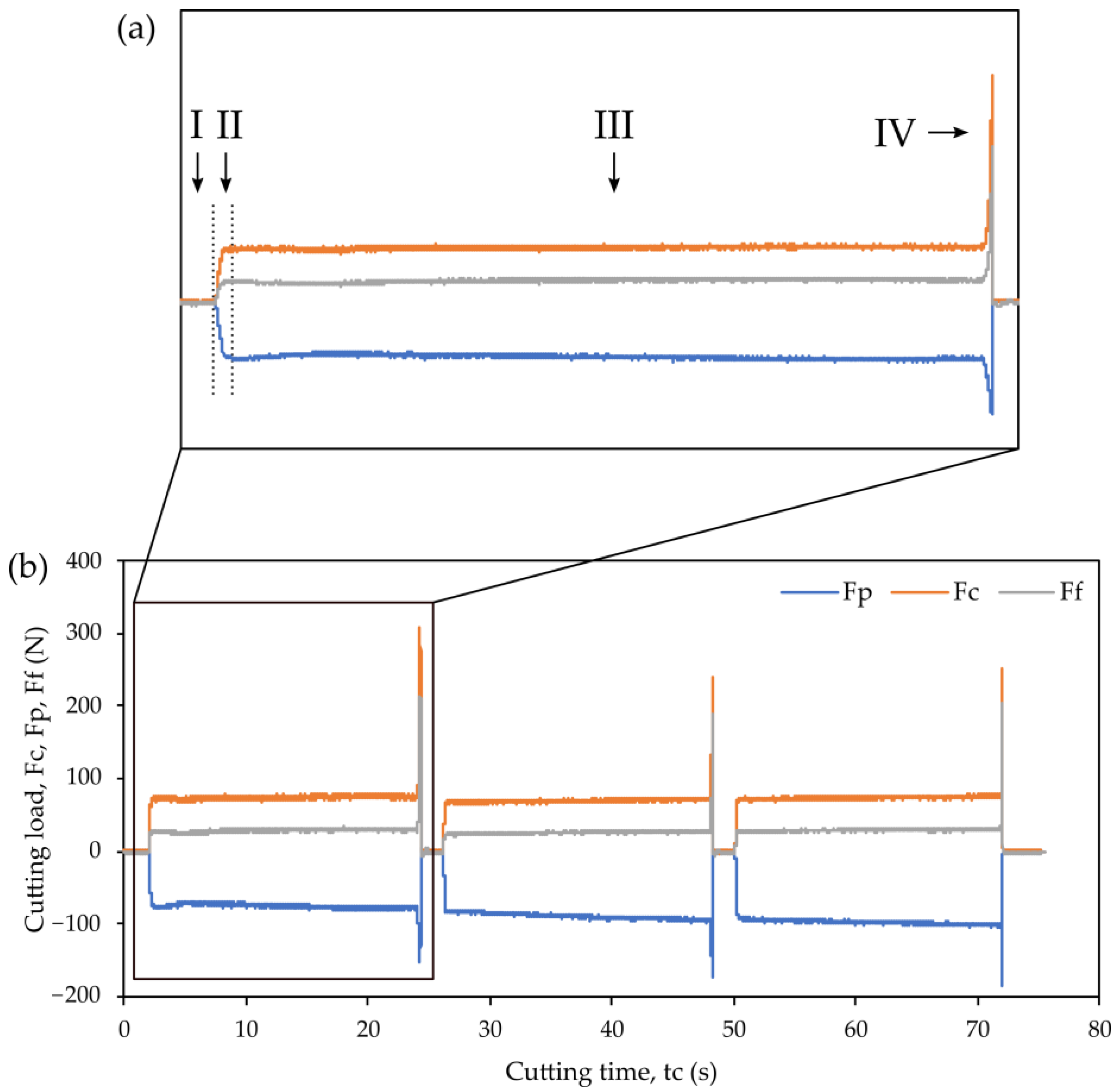
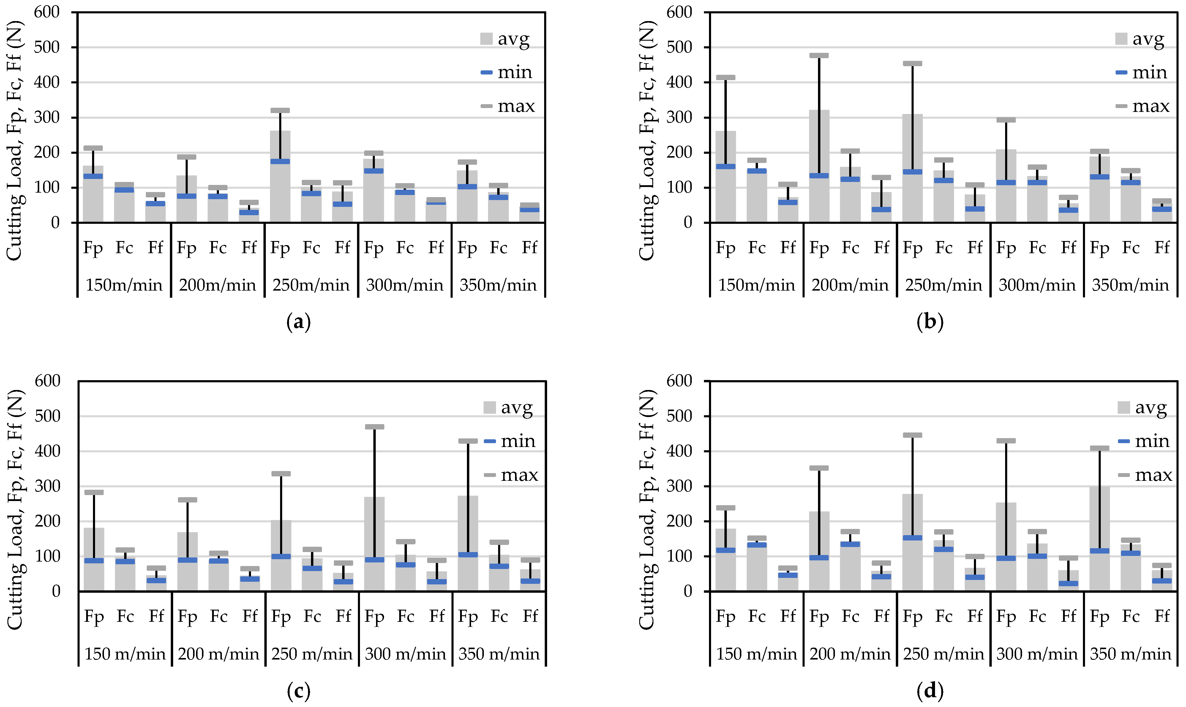
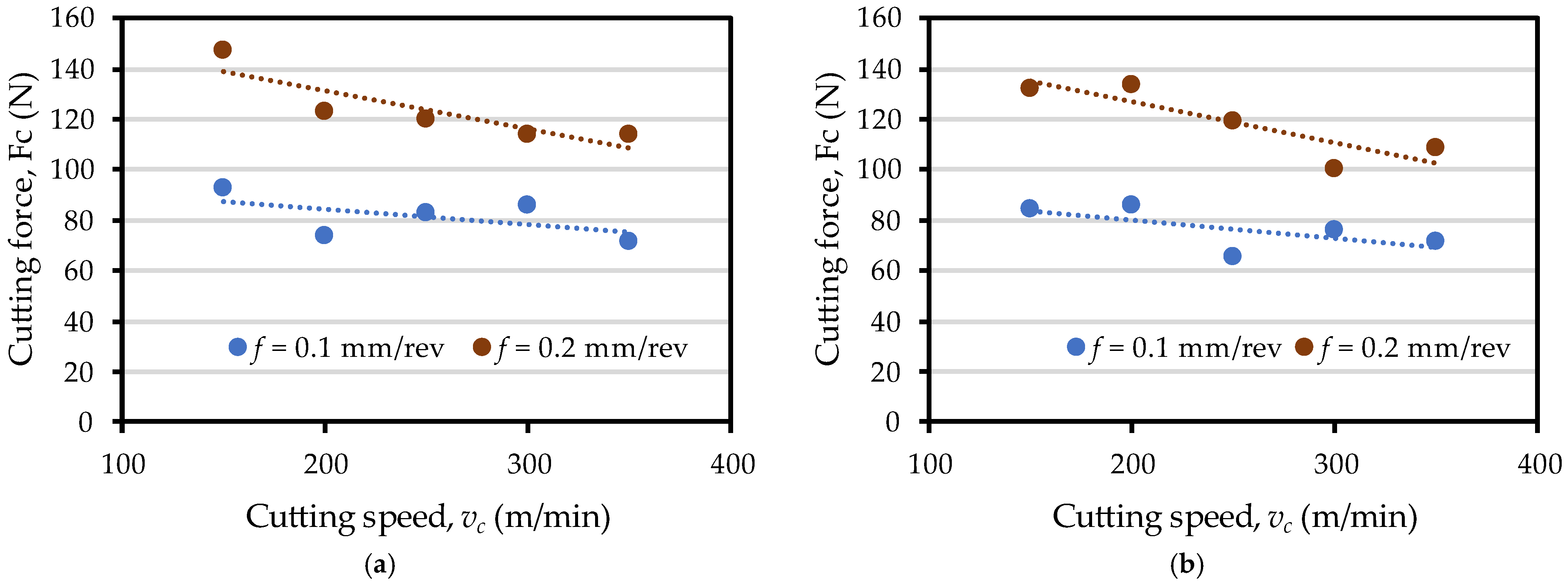
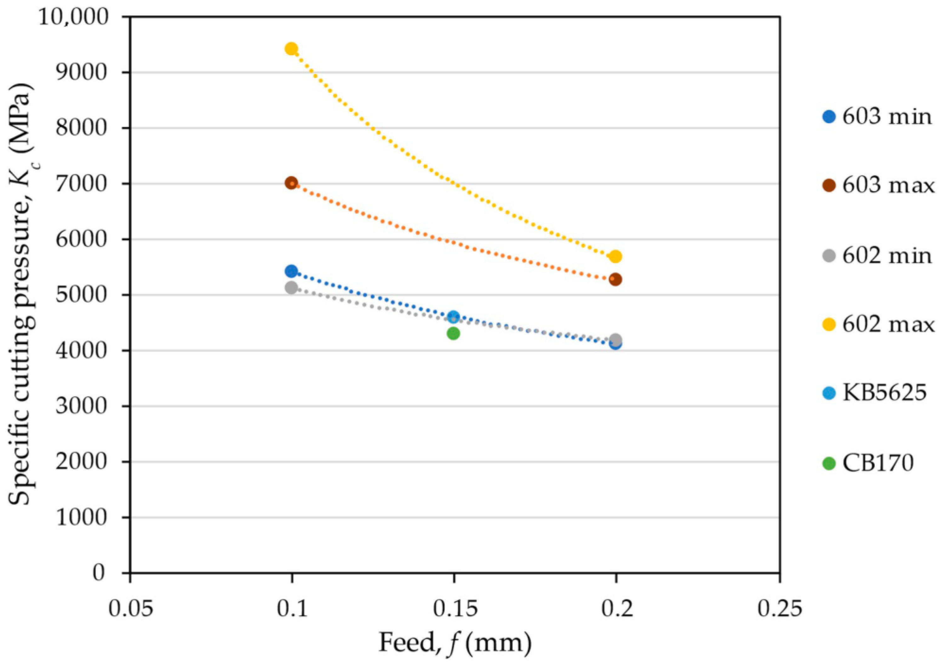
3.2. Cutting Load
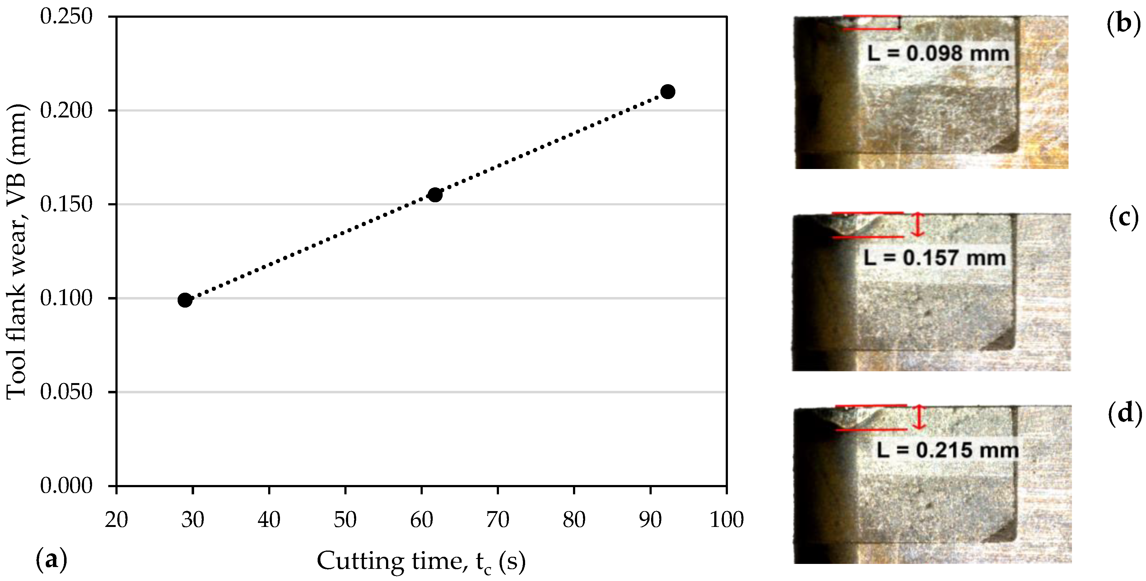
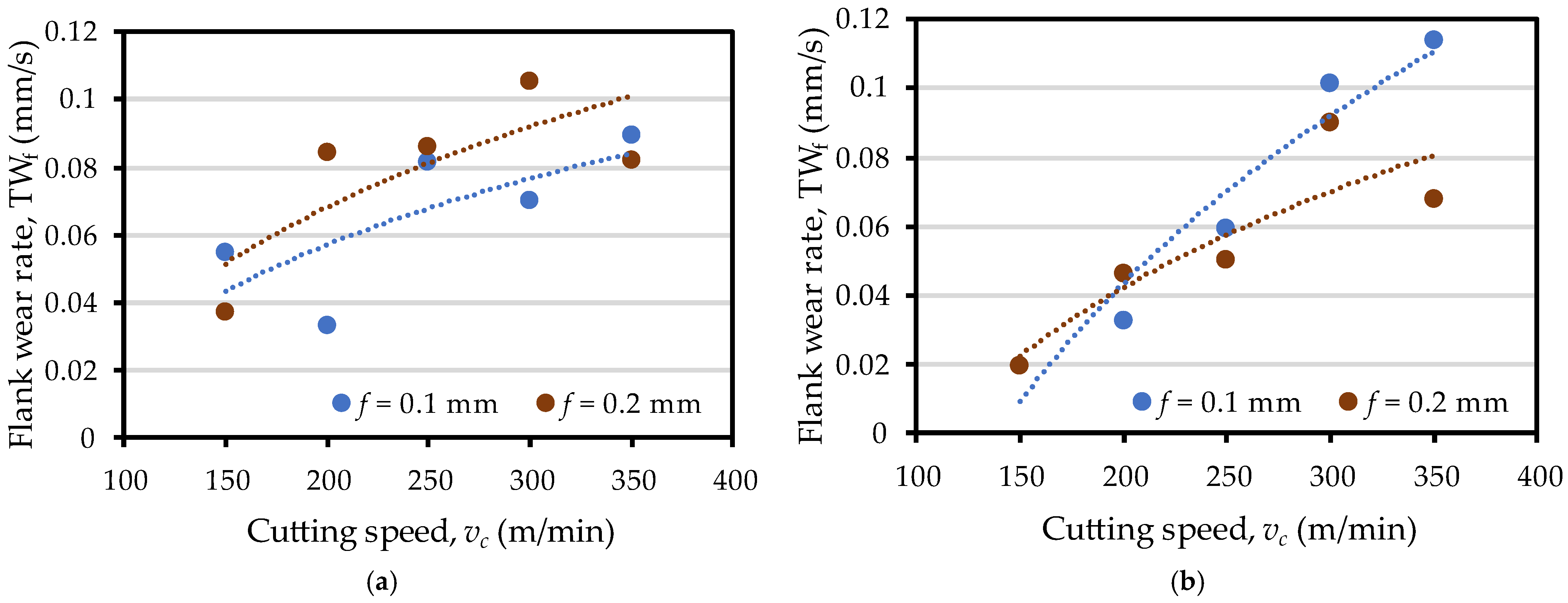
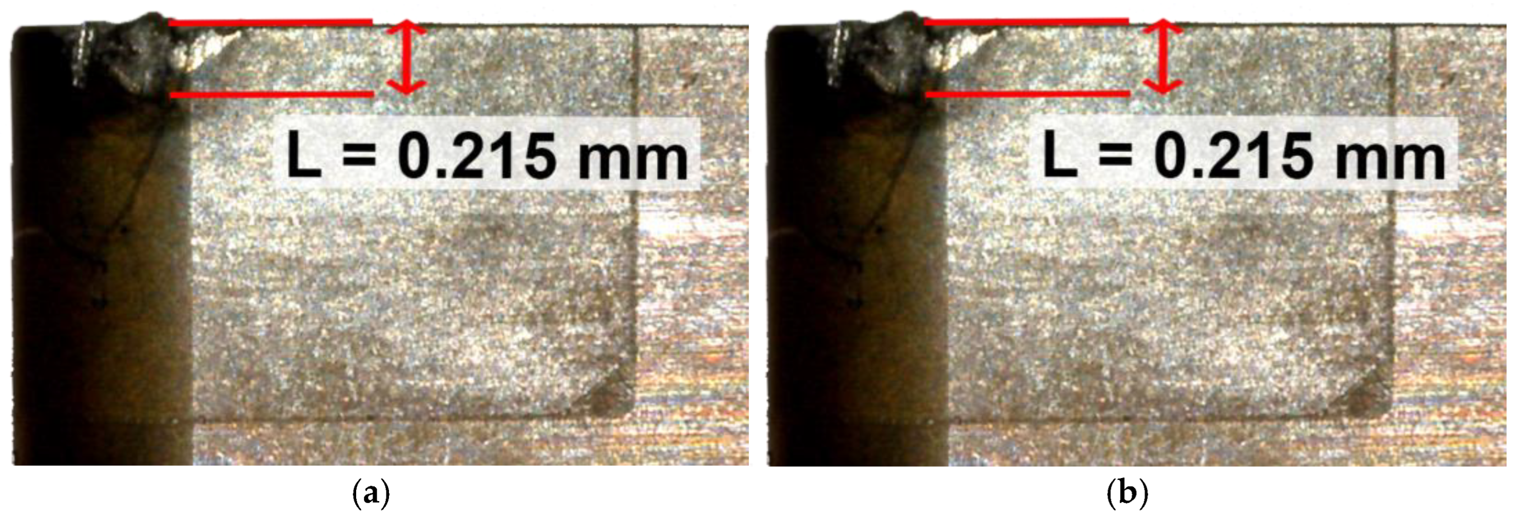
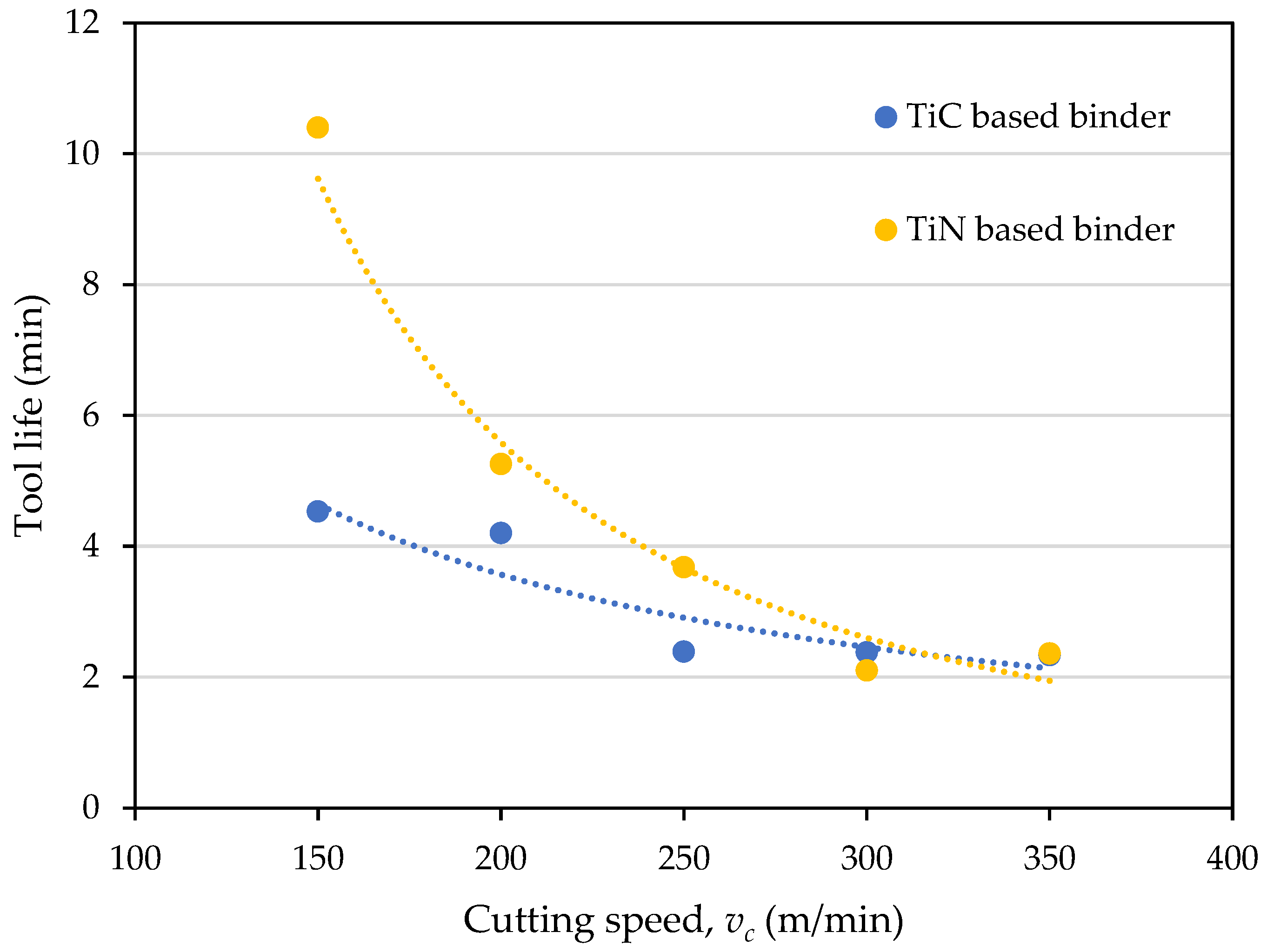
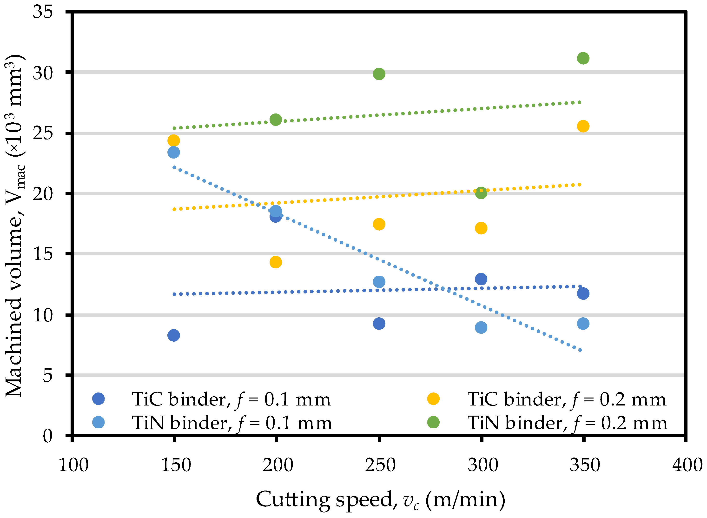
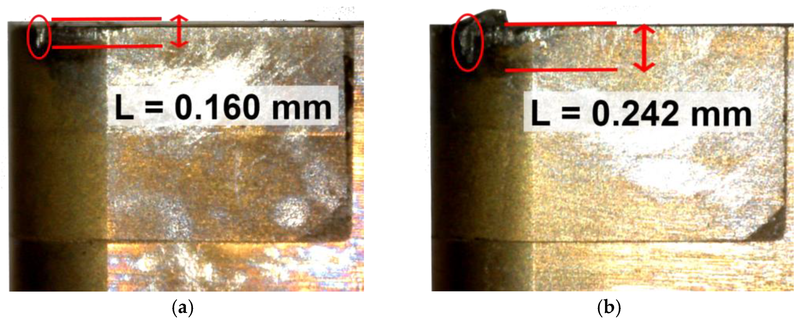
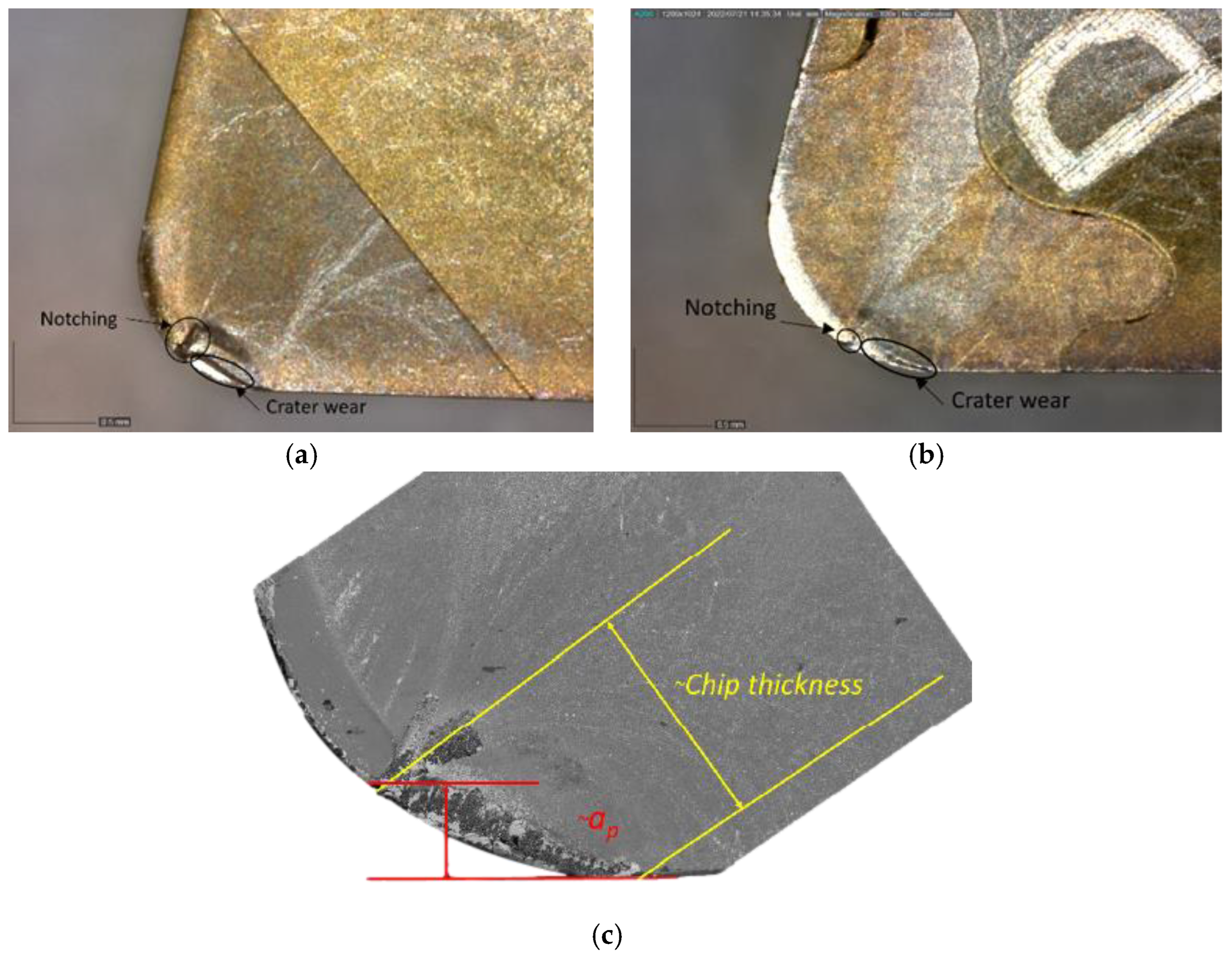
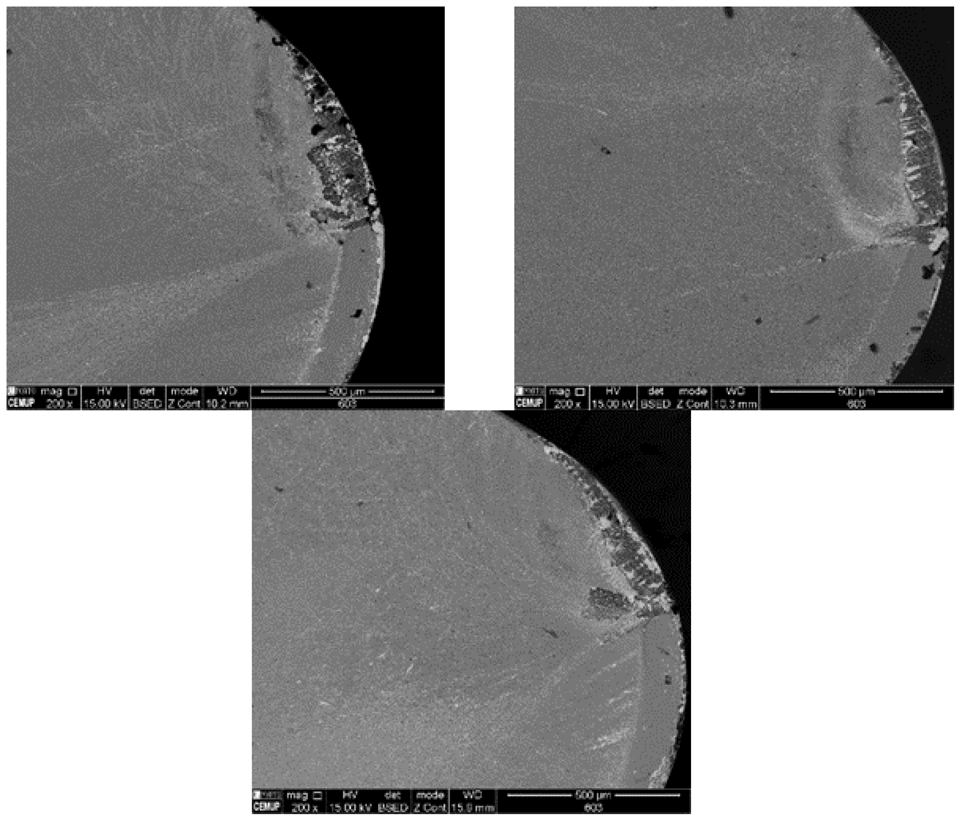
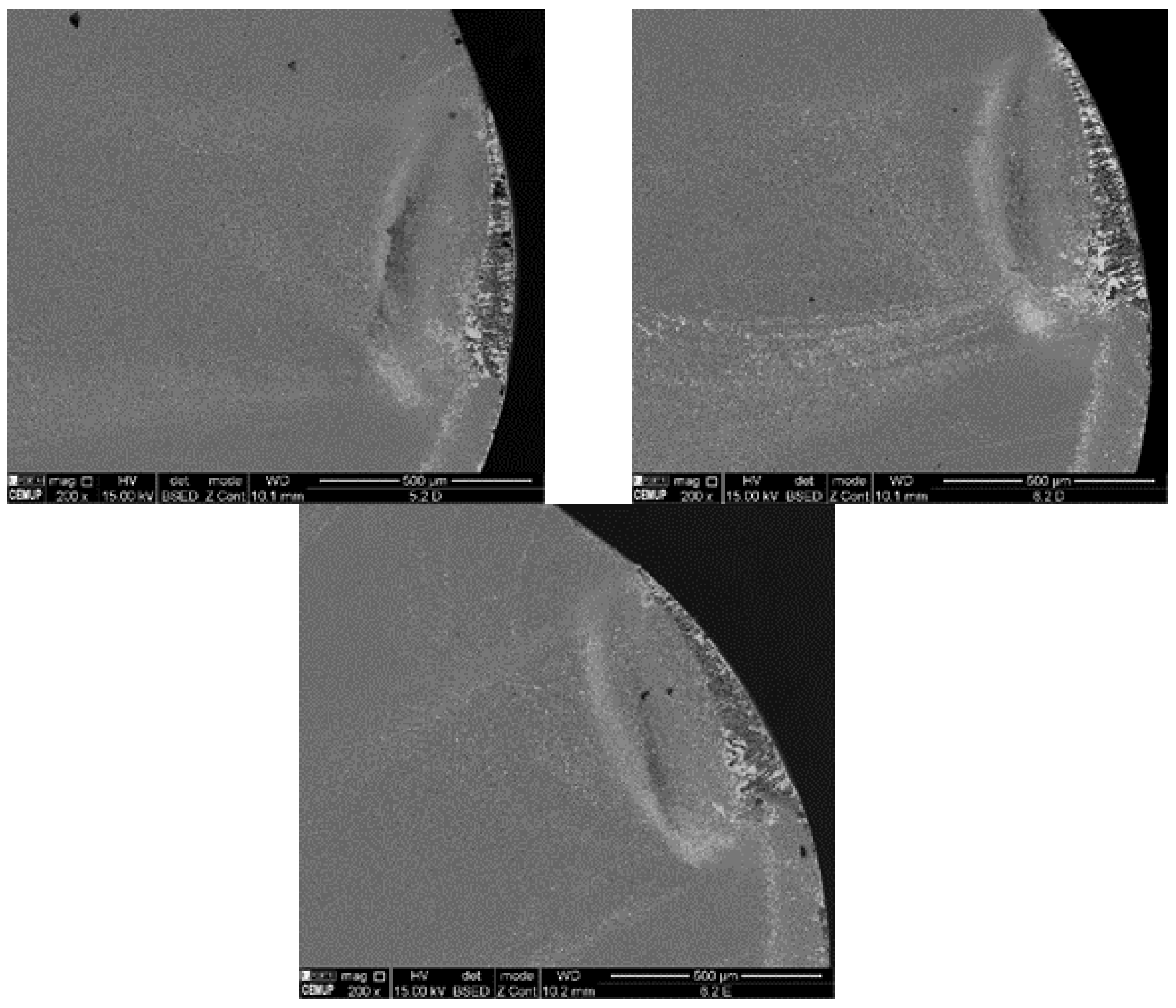
3.3. Tool Wear
4. Conclusions
- In terms of the cutting forces, there is a clear dependence between the obtained values and the adopted cutting parameters. The main cutting force increases for higher feed rates and decreases for higher cutting speeds;
- Increasing the cutting speed (𝑣𝑐 > 300 m/min) seems to promote a change in the dominant wear mode, from mechanical abrasion to chemical diffusion, as evidenced by the type of tool wear noticed in the cutting tools;
- Low-content PCBN tools are suitable to machine Inconel 718 at high cutting speeds (250 < 𝑣𝑐 < −350 m/min) and low depth of cut (0.15 mm). At lower cutting speeds (150 < 𝑣𝑐 < 200 m/min), notching and chipping are the main causes of wear, resulting in instability of the cutting operation and leading to unpredictable tool failure. At high cutting speeds, adhesion and diffusion of Inconel 718 into the tool surface deteriorate the cutting edge’s geometry and toughness;
- Lower cutting speeds and the lack of chip breaker resulted in poor chip control at low cutting speeds, and there was a tendency of chips to entangle around the workpiece. Increasing the cutting speed was favorable to the appearance of the chip segmentation;
- Of all forces involved in the turning operation, passive force was the greatest, which is typical when the depth of cut is smaller than the nose radius of the tool, and showed an evolution that was close with the increase in tool wear;
- The results of the experiment indicate that a higher removal rate does not always lead to a corresponding decrease in the durability of the cutting tool, which may ultimately enable more productive cutting conditions in terms of productivity. This highlights the potential of using PCBN tools when turning Inconel 718;
- TiN binder seemed to improve the tool resistance when machining this superalloy; yet, more experiments should be conducted, particularly focusing on the evaluation of the tool’s thermal evolution through combined approaches of in situ temperature measurement and numerical modeling allowing for an assessment of the wear performance and stability for different ranges of temperature (promoted by distinct operational conditions). The chemical stability of the tested tools can also be assessed under distinct lubrication conditions.
Author Contributions
Funding
Institutional Review Board Statement
Informed Consent Statement
Data Availability Statement
Conflicts of Interest
References
- Mouritz, A.P. Introduction to aerospace materials. In Introduction to Aerospace Materials; Woodhead Publishing: Sawston, UK, 2012; pp. 1–14. [Google Scholar]
- Choudhury, I.A.; El-Baradie, M.A. Machinability of nickel-base super alloys: A general review. J. Mater. Process. Technol. 1998, 77, 278–284. [Google Scholar] [CrossRef]
- Buddaraju, K.M.; Sastry, G.R.K.; Kosaraju, S. A review on turning of Inconel alloys. Mater. Today Proc. 2021, 44, 2645–2652. [Google Scholar] [CrossRef]
- Ulutan, D.; Ozel, T. Machining induced surface integrity in titanium and nickel alloys: A review. Int. J. Mach. Tools Manuf. 2011, 51, 250–280. [Google Scholar] [CrossRef]
- Asala, G.; Andersson, J.; Ojo, O.A. A study of the dynamic impact behaviour of IN 718 and ATI 718Plus® superalloys. Philos. Mag. 2019, 99, 419–437. [Google Scholar] [CrossRef]
- Shalaby, M.A.; Veldhuis, S.C. Tool wear and chip formation during dry high speed turning of direct aged Inconel 718 aerospace superalloy using different ceramic tools. J. Eng. Tribol. 2019, 233, 1127–1136. [Google Scholar] [CrossRef]
- Zhou, J.; Bushlya, V.; Avdovic, P.; Ståhl, J.E. Study of surface quality in high speed turning of Inconel 718 with uncoated and coated CBN tools. Int. J. Adv. Manuf. Technol. 2012, 58, 141–151. [Google Scholar] [CrossRef]
- Agmell, M.; Bushlya, V.; M’saoubi, R.; Gutnichenko, O.; Zaporozhets, O.; Laakso, S.V.; Ståhl, J.-E. Investigation of mechanical and thermal loads in pcBN tooling during machining of Inconel 718. Int. J. Adv. Manuf. Technol. 2020, 107, 1451–1462. [Google Scholar] [CrossRef]
- Rahman, M.; Seah, W.K.H.; Teo, T.T. The machinability of Inconel 718. J. Mater. Process. Technol. 1997, 63, 199–204. [Google Scholar] [CrossRef]
- Sousa, V.F.C.; Silva, F.J.G. Recent Advances on Coated Milling Tool Technology—A Comprehensive Review. Coatings 2020, 10, 235. [Google Scholar] [CrossRef]
- Wojciechowski, S.; Przestacki, D.; Chwalczuk, T. The Evaluation of Surface Integrity During Machining of Inconel 718 with Various Laser Assistance Strategies. MATEC Web Conf. 2017, 136, 01006. [Google Scholar] [CrossRef]
- Burghardt, A.; Szybicki, D.; Kurc, K.; Muszyñska, M.; Mucha, J. Experimental Study of Inconel 718 Surface Treatment by Edge Robotic Deburring with Force Control. Strength Mater. 2017, 49, 594–604. [Google Scholar] [CrossRef]
- Sousa, V.F.C.; Da Silva, F.J.G.; Pinto, G.F.; Baptista, A.; Alexandre, R. Characteristics and Wear Mechanisms of TiAlN-Based Coatings for Machining Applications: A Comprehensive Review. Metals 2021, 11, 260. [Google Scholar] [CrossRef]
- Fallbohmer, P.; Rodrigues, C.A.; Ozel, T.; Altan, T. High-speed machining of cast iron and alloy steels for die and mold man-ufacturing. J. Mater. Process. Technol. 2000, 98, 104–115. [Google Scholar] [CrossRef]
- Liao, Y.; Lin, H. Mechanism of minimum quantity lubrication in high-speed milling of hardened steel. Int. J. Mach. Tools Manuf. 2007, 47, 1660–1666. [Google Scholar] [CrossRef]
- Wang, B.; Liu, Z.Q.; Cai, Y.K.; Luo, X.C.; Ma, H.F.; Song, Q.H.; Xiong, Z.H. Advancements in material removal mechanism and surface integrity of high speed metal cutting: A review. Int. J. Mach. Tools Manuf. 2021, 166, 103744. [Google Scholar] [CrossRef]
- Ezugwu, E.O. High speed machining of aero-engine alloys. J. Braz. Soc. Mech. Sci. Eng. 2004, 26, 1–11. [Google Scholar] [CrossRef]
- Tu, L.Q.; Ming, W.W.; Xu, X.W.; Cai, C.Y.; Chen, J.; An, Q.L.; Xu, J.Y.; Chen, M. Wear and failure mechanisms of SiAlON ceramic tools during high-speed turning of nickel-based superalloys. Wear 2022, 488–489, 204171. [Google Scholar] [CrossRef]
- Dudzinski, D.; Devillez, A.; Moufki, A.; Larrouquère, D.; Zerrouki, V.; Vigneau, J. A review of developments towards dry and high speed machining of Inconel 718 alloy. Int. J. Mach. Tools Manuf. 2004, 44, 439–456. [Google Scholar] [CrossRef]
- Toenshoff, H.K.; Denkena, B. Basics of Cutting and Abrasive Processes; Springer: Berlin/Heidelberg, Germany, 2013. [Google Scholar] [CrossRef]
- Criado, V.; Alvarez, J.D.; Cantero, J.L.; Miguélez, M.H. Study of the performance of PCBN and carbide tools in finishing ma-chining of Inconel 718 with cutting fluid at conventional pressures. Procedia CIRP 2018, 77, 634–637. [Google Scholar] [CrossRef]
- Giménez, S.; Van der Biest, O.; Vleugels, J. The role of chemical wear in machining iron based materials by PCD and PCBN super-hard tool materials. Diam. Relat. Mater. 2007, 16, 435–445. [Google Scholar] [CrossRef]
- Zhangiang, L.; Xing, A. Cutting tool materials for high speed machining. Prog. Nat. Sci. 2005, 15, 777–783. [Google Scholar] [CrossRef]
- Costes, J.; Guillet, Y.; Poulachon, G.; Dessoly, M. Tool-life and wear mechanisms of CBN tools in machining of Inconel 718. Int. J. Mach. Tools Manuf. 2007, 47, 1081–1087. [Google Scholar] [CrossRef]
- Bushlya, V.; Zhou, J.; Avdovic, P.; Ståhl, J.-E. Performance and wear mechanisms of whisker-reinforced alumina, coated and uncoated PCBN tools when high-speed turning aged Inconel 718. Int. J. Adv. Manuf. Technol. 2013, 66, 2013–2021. [Google Scholar] [CrossRef]
- Khan, S.; Soo, S.; Aspinwall, D.; Sage, C.; Harden, P.; Fleming, M.; White, A.; M’Saoubi, R. Tool wear/life evaluation when finish turning Inconel 718 using PCBN tooling. Procedia CIRP 2012, 1, 283–288. [Google Scholar] [CrossRef]
- Soo, S.L.; Khan, S.A.; Aspinwall, D.K.; Harden, P.; Mantle, A.L.; Kappmeyer, G.; Pearson, D.; M’Saoubi, R. High speed turning of Inconel 718 using PVD-coated PCBN tools. CIRP Ann. 2016, 65, 89–92. [Google Scholar] [CrossRef]
- Bushlya, V.; Zhou, J.; Ståhl, J. Effect of Cutting Conditions on Machinability of Superalloy Inconel 718 During High Speed Turning with Coated and Uncoated PCBN Tools. Procedia CIRP 2012, 3, 370–375. [Google Scholar] [CrossRef]
- Bushlya, V.; Bjerke, A.; Turkevich, V.Z.; Lenrick, F.; Petrusha, I.A.; Cherednichenko, K.A.; Stahl, J.E. On chemical and diffu-sional interactions between PCBN and superalloy Inconel 718: Imitational experiments. J. Europ. Ceramic Soc. 2019, 39, 2658–2665. [Google Scholar] [CrossRef]
- Sugihara, T.; Tanaka, H.; Enomoto, T. Development of Novel CBN Cutting Tool for High Speed Machining of Inconel 718 Focusing on Coolant Behaviors. Procedia Manuf. 2017, 10, 436–442. [Google Scholar] [CrossRef]
- Sousa, V.F.C.; Silva, F.J.G. Recent Advances in Turning Processes Using Coated Tools—A Comprehensive Review. Metals 2020, 10, 170. [Google Scholar] [CrossRef]
- Slama, C.; Servant, C.; Cizeron, G. Aging of Inconel 718 alloy between 500 and 750 °C. J. Mater. Res. 1997, 12, 2298–2316. [Google Scholar] [CrossRef]
- Azarbarmas, M.; Aghaie-Khafri, M.; Cabrera, J.; Calvo, J. Dynamic recrystallization mechanisms and twining evolution during hot deformation of Inconel 718. Mater. Sci. Eng. A 2016, 678, 137–152. [Google Scholar] [CrossRef]
- Wu, Z.; Parish, C.; Bei, H. Nano-twin mediated plasticity in carbon-containing FeNiCoCrMn high entropy alloys. J. Alloy. Compd. 2015, 647, 815–822. [Google Scholar] [CrossRef]
- Cantero, J.L.; Díaz-Álvarez, J.; Infante-García, D.; Rodríguez, M.; Criado, V. High Speed Finish Turning of Inconel 718 Using PCBN Tools under Dry Conditions. Metals 2018, 8, 192. [Google Scholar] [CrossRef]
- Huang, Y.; Liang, S.Y. Modeling of Cutting Forces Under Hard Turning Conditions Considering Tool Wear Effect. J. Manuf. Sci. Eng. 2005, 127, 262–270. [Google Scholar] [CrossRef]
- Bouacha, K.; Yallese, M.A.; Mabrouki, T.; Rigal, J.-F. Statistical analysis of surface roughness and cutting forces using response surface methodology in hard turning of AISI 52100 bearing steel with CBN tool. Int. J. Refract. Met. Hard Mater. 2010, 28, 349–361. [Google Scholar] [CrossRef]
- Wanner, B.; Eynian, M.; Beno, T.; Pejryd, L. Process stability strategies in milling of thin-walled Inconel 718. AIP Conf. Procc. 2012, 1431, 465. [Google Scholar] [CrossRef]
- Silva, T.E.; Amaral, A.; Couto, A.; Coelho, J.; Reis, A.; Rosa, P.A.; de Jesus, A.M. Comparison of the machinability of the 316L and 18Ni300 additively manufactured steels based on turning tests. J. Mater. Des. Appl. 2021, 235, 2207–2226. [Google Scholar] [CrossRef]
- Bushlya, V.; Lenrick, F.; Bjerke, A.; Aboulfadl, H.; Thuvander, M.; Ståhl, J.-E.; M’Saoubi, R. Tool wear mechanisms of PcBN in machining Inconel 718: Analysis across multiple length scale. CIRP Ann. 2021, 70, 73–78. [Google Scholar] [CrossRef]
- Bhattacharyya, S.K.; Jawaid, A.; Lewis, M.H.; Wallbank, J. Wear mechanisms of Syalon ceramic tools when machining nick-el-bases materials. Metals Technol. 1983, 10, 482–489. [Google Scholar] [CrossRef]
- Xue, C.; Wang, D.; Zhang, J. Wear Mechanisms and Notch Formation of Whisker-Reinforced Alumina and Sialon Ceramic Tools during High-Speed Turning of Inconel 718. Materials 2022, 15, 3860. [Google Scholar] [CrossRef]
- Tampieri, A.; Bellosi, A. Oxidation Resistance of Alumina-Titanium Nitride and Alumina-Titanium Carbide Composites. J. Am. Ceram. Soc. 1992, 75, 1688–1690. [Google Scholar] [CrossRef]


| Temp. | Yield S. (MPa) | Tensile S. (Mpa) | Elongation (%) | Area Reduction (%) |
|---|---|---|---|---|
| RT | 52.70 | 19.06 | 18.43 | 4.73 |
| 649 °C | 50.00 | rem | 17.00 | 4.75 |
| Cutting Parameter | Levels | ||||
|---|---|---|---|---|---|
| Depth of cut, (mm) | 0.15 | ||||
| Feed, (mm) | 0.1 | 0.2 | |||
| Cutting speed, (m/min) | 150 | 200 | 250 | 300 | 350 |
| Element | Ni | Fe | Cr | Nb | Mo | Ti | Al | W | Si | Co |
|---|---|---|---|---|---|---|---|---|---|---|
| Measured | 52.70 | 19.06 | 18.43 | 4.73 | 3.00 | 1.02 | 0.541 | 0.114 | 0.114 | 0.109 |
| Standard min. | 50.00 | rem | 17.00 | 4.75 | 2.80 | 0.65 | 0.20 | - | - | - |
| Standard max. | 55.00 | - | 21.00 | 5.50 | 3.30 | 1.15 | 0.80 | 0.35 | 0.35 | 1.00 |
| Insert | VB | Average | ||
|---|---|---|---|---|
| #1 | #2 | #3 | ||
| TiC | 0.099 | 0.082 | 0.085 | 0.089 |
| TiN | 0.089 | 0.061 | 0.058 | 0.069 |
Disclaimer/Publisher’s Note: The statements, opinions and data contained in all publications are solely those of the individual author(s) and contributor(s) and not of MDPI and/or the editor(s). MDPI and/or the editor(s) disclaim responsibility for any injury to people or property resulting from any ideas, methods, instructions or products referred to in the content. |
© 2023 by the authors. Licensee MDPI, Basel, Switzerland. This article is an open access article distributed under the terms and conditions of the Creative Commons Attribution (CC BY) license (https://creativecommons.org/licenses/by/4.0/).
Share and Cite
Matos, F.; Silva, T.E.F.; Sousa, V.F.C.; Marques, F.; Figueiredo, D.; Silva, F.J.G.; Jesus, A.M.P.d. On the Influence of Binder Material in PCBN Cutting Tools for Turning Operations of Inconel 718. Metals 2023, 13, 934. https://doi.org/10.3390/met13050934
Matos F, Silva TEF, Sousa VFC, Marques F, Figueiredo D, Silva FJG, Jesus AMPd. On the Influence of Binder Material in PCBN Cutting Tools for Turning Operations of Inconel 718. Metals. 2023; 13(5):934. https://doi.org/10.3390/met13050934
Chicago/Turabian StyleMatos, Francisco, Tiago E. F. Silva, Vitor F. C. Sousa, Francisco Marques, Daniel Figueiredo, Francisco J. G. Silva, and Abílio M. P. de Jesus. 2023. "On the Influence of Binder Material in PCBN Cutting Tools for Turning Operations of Inconel 718" Metals 13, no. 5: 934. https://doi.org/10.3390/met13050934