Article

Effect of Wear on Vibration Amplitude and Chip Shape Characteristics during Machining of Eco-Friendly and Leaded Brass Alloys

by
Peter Pavol Monka
1,2,
Katarina Monkova
1,2,*,
George A. Pantazopoulos
3,* and
Anagnostis I. Toulfatzis
3
1
Faculty of Manufacturing Technologies, Technical University in Kosice, Sturova 31, 080 01 Presov, Slovakia
2
Faculty of Technology, Tomas Bata University in Zlin, Nam. T.G. Masaryka 275, 760 01 Zlin, Czech Republic
3
ELKEME Hellenic Research Centre for Metals S.A., 61st km Athens—Lamia National Road, 32011 Oinofyta, Greece
*
Authors to whom correspondence should be addressed.
Metals 2023, 13(5), 828; https://doi.org/10.3390/met13050828
Submission received: 31 March 2023 / Revised: 18 April 2023 / Accepted: 20 April 2023 / Published: 23 April 2023
(This article belongs to the Special Issue Machinability and Tribological Performance of Advanced Alloys)

Abstract

:
The dynamic stability of the machining set and the entire cutting process, together with the appropriate form of chips generated during machining under the given conditions, are the basic prerequisites for autonomous machining in accordance with the Industry 4.0 trend. The research, based on a newly designed method, aims to study the frequency response of the machining system to different values of tool wear and cutting speed, which cause the worsening of the machined parts’ quality and the instability of the whole cutting process. The new idea is based on the inverse principle, in which the wear with various values of VB was artificially prepared in advance before machining. Consequently, the effect of artificial wear and cutting speed on vibration and chip shape characteristics were studied. Three types of brass alloys were used within the experiments as the machined materials. Measured data were statistically processed and the desired dependencies were plotted. Chips were collected for each combination of machining conditions, while the article presents a database of the obtained chip shapes at individual cutting speeds so that they can be compared and classified. The results showed that brass alloys CW510L and CW614N exhibit an average of three times lower vibration damping compared to the CW724R alloy, while relatively good chip formation was noted in the evaluated machining conditions even without the use of a chip breaker. The problematic chip shape occurred only in some cases at the machining of CW510L and CW724R, which cannot be generalized.

1. Introduction

Material removal has been a significant set of operations in production since the beginning of the Industrial Revolution. Its importance is highlighted by the significant contribution of machining to the development of the industry by enabling the development of new, more precise and efficient technological solutions. This field includes concentrated knowledge in a wide range of expertise—physical laws, chemistry, mathematics, material sciences, technical sciences, economic disciplines, environmental research, and many others.
Cutting off the material rate (measured by the machined volume over time) and durability of the cutting tool (represented by the duration of its work) are considered the most important results of the cutting process [1,2,3].
The results of the cutting process are directly influenced by machining environment variation, while the most important factors are [1]: Cutting tool; Workpiece; Machine Tool; Technological Process; and Technological Settings.
Following the rules of economic efficiency, ecological reform demands, societal regulations, and high demands for constant refinement of production (micro and nano dimensions), the complexities of the above factors unite in a significant way. Therefore, the integrity of modern machining systems requires a very precise and demanding design and formulation with optimization for the given production conditions [4,5].
In the finally determined production system (given mainly by the product, machine tool, cutting tool, and process), only cutting factors can be used for the optimization of efficiency and productivity (durability of cutting tool and material removal rate). Generally, the basic cutting factors are depth of cut, feed, and cutting speed. However, the depth of cut can be a factor related to machining efficiency that increases only in the case of small series and piece production if it is not possible to provide material with dimensions and shapes close to the manufactured product. In that case, it is an operation with an inefficient use of input material, and such a production method would need to be optimized for the application of more economical technologies. Therefore, it is not assumed that this factor will be used for optimization. The general effect of depth of cut ap on durability T is shown in Figure 1a [1,6].
Feed rate linearly affects productivity. However, its speed is limited by the required quality parameters of the final surfaces, and therefore the value of this speed cannot be increased without special solutions, e.g., smoothing geometry of the cutting tool, etc. The general effect of feed f on durability T is shown in Figure 1b [1].
Cutting speed affects machining productivity in a linear relationship, but tool life, expressed by cutting ability, is degraded exponentially. The relationship between these two physical regularities of the cutting tool is determined by the kinematics of the machine tool and the events (both physical and chemical) in contact between the tool and the machined material. The general effect of cutting speed vc on durability T is documented in Figure 1c. This dependence shows the region appropriate for the good relationship of cutting speed and durability of the tool [1,7,8].
The next important parameter that enters the machining process is temperature. The general regularities of the influence of the temperature reached at the point of the cut on the nonlinearity of the course of the investigated factors are shown in Figure 2. The temperature mainly depends on the type of machined material, the rate of deformation in shear volume, the friction conditions on the front and back plane of the tool, and the cooling characteristics of the process. All these physical factors are also influenced by variations in other factors of the machining environment, as mentioned above.
The dependence of the achieved wear limit on the cutting speed is also a very important regulator of machining. The wear limit is the maximum value of admissible degradation of the cutting edge, at which the admissible quality characteristic of the workpiece surface by machining can still be achieved [9,10]. In the given conditions, wear of the flank or face on the cutting tool depends not only on the type of machined material but also on the proportion between feed and cutting speed. The dimensions of worn parts of the tool are usually specified by [11]:
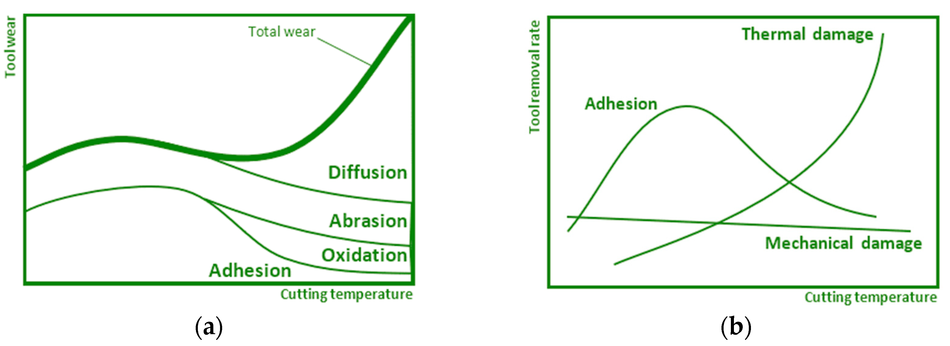
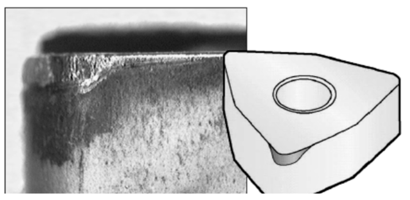
  • VB—width of the wear area on the flank;
  • KT—depth of wear groove on the face;
  • KVs—wear of the tool corner by wear.
An effective machining process requires controlling and checking the tool’s wear propagation. The best way of the wear propagation is uniform flank wear of the cutting insert as shown in Figure 3.
Tool wear is closely related to tool durability since it directly affects the tool’s durability and life. Figure 4 presents the dependence of the decrease in durability on the cutting speed for the determined wear limit and the area of degradation effects as a function of the overall cutting time T on the cutting speed vc in logarithmic coordinates [12,13].
Following the above it can be said that the joint action of a group of factors in the production system (tools and tool materials, tool geometry, tool coating, and procedural media), as well as groups of process factors (cutting speed, depth of cut, and feed) creates the resulting heat generation and degradation indices of the tool. The intensity of abrasion appears to be a relationship between a combination of processed material and cutting tool, and in terms of the dependence of the tool wear on the achieved cutting temperature, it shows quasi-static characteristics. The adhesion intensity slowly increases as the cutting temperature increases and gradually decreases when the temperature of the diffusion and oxidation processes is reached. The oxidation intensity begins to develop after critical cutting temperatures and its magnitude stabilizes when the maximum saturation is reached. The intensity of the diffusion processes is imperceptible at low cutting temperatures and increases very progressively when the critical cutting temperature is reached.
Several studies have already dealt with machining process monitoring in which the influence of cutting conditions on the machining set and system stability was investigated. Dimla [14] identified that time domain features were deemed to be more sensitive to cutting conditions than tool wear, whereas frequency-based features correlated well with the tool wear and measured wear values correlated well with certain resonant peak frequencies. Chuangwen [15] obtained results for 022Cr17Ni12Mo2 stainless steel where the root-mean-square value of vibration acceleration signals increased with wear progression in general. Bouhalais [16] confirmed a good match between high-frequency vibration components’ energy values and tool wear monitoring. Sridhar [17] found ten times larger vibration amplitudes of a worn drill compared to a sharp one. Babu [18] found that the correlation of experimentally measured tool wear with tool acceleration is practically feasible for real-time flank wear prediction at any time. Antic [19] noted that most research studies on the development of tool wear monitoring systems focus on the type of machining and the machining process to which they are applicable. The types and types of input signals, methods and techniques of signal processing and feature extraction are not primarily considered. This approach limits the scope of the investigation. Data processing of the instrument monitoring system proposed by Anticom includes these steps: signal acquisition and processing; data classification by grouping into an input function; and definition of tool wear status [19].
The study of the effect of conditions on the machining process and the durability of the tool can generally be carried out by tests categorized into two groups: short-term and long-term tests. Short-term durability tests are more commonly used in practice because of shorter time and less amount of processed material, but also for efficiency and economy. This testing is employed usually as the first step in checking the material of a workpiece or as a quick comparison of the durability of the examined cutting tools with a standardized etalon [20]. The principle of the short-term test, in which the material is removed by facing, consists in machining a workpiece with a relatively large diameter (Dmax is about 300 mm). The material is removed in the radial direction, i.e., from a pre-drilled coaxial hole in the center of the workpiece towards the edge of the disc. This means that the cutting speed gradually increases, and, at a specific Dn diameter, the cutting speed reaches the maximum vn value at which the ability to cut the material is lost. Pastucha et al. [21] have proposed a prospective variant to a short-term test, which is based on discontinuous cutting thus leading to higher intensity of tool wear to make this method more effective. In this method, the workpiece is radially placed on a large-diameter disk, while the cutting tool removes the material from the workpiece in circular segments.
However, the short-term tests described above also have their weaknesses. Except for certain short-term tests where the cutting speed is not constant, making it difficult to evaluate the effect of cutting speed on tool wear, such types of tests are not applicable when the workpieces with a larger diameter are for various reasons unavailable, or the turning machine does not allow workpieces with such a large diameter to be clamped.
These disadvantages were taken into account in the present study, and in order to eliminate them, the authors proposed a new methodology for investigating the appearance of tool wear that can be considered a novelty and a contribution of the authors to the scientific field. Since the dynamic stability of the machining set and the entire cutting process, together with the appropriate form of chips generated during machining under the given conditions, are the basic prerequisites for autonomous machining in accordance with the Industry 4.0 trend, it is, therefore, important to deal with this issue.
Manufacturing within Industry 4.0 is planned and programmed to perform tasks with minimal human intervention, with autonomous manufacturing equipment varying greatly in size and function, from drone inventory scanning to autonomous mobile robots for pick and place operations. Equipped with cutting-edge software, artificial intelligence, sensors and machine vision, the devices are capable of performing demanding and delicate tasks. They should be able to recognize, analyze, and act on the information they receive from their surroundings. It is very important to ensure that the manufacturing machines work smoothly and that the impact of external conditions causing problems was eliminated where possible. A number of such problems can be caused by inappropriate chip shaping. Too short chips cause intermittent machining, which leads to micro-cracks on the cutting edge and shortens the tool life. In terms of life, long chips are slightly more favorable. Long, smooth-shaped chips show less micro-vibration when machining, which contributes to improving the quality of the machined surface. For the cutting process itself, however, long chips are also not suitable. Long chips can cause the cutting tool to become tangled and lose its ability to cut. They may damage the machine tool, workpiece, and cutting tool, and induce dangerous working conditions for operators. They can also cause problems with jamming in the conveyor and outages in operation. Thus, inappropriate chip problems can cause the cutting process not to be autonomous and will therefore not be suitable for inclusion in the automated process.
Based on these trends in the automation of production processes and their requirements, the present research focused on knowing the frequency response of the system for various tool wear values, resulting in deterioration of the quality of the processed parts and unsteadiness of the whole cutting operation. Understanding and knowledge of the behavior trend of vibration characteristics allow not only setting the most suitable technological conditions for machining the given material and thus increasing the tool life but also comparing the durability of the tool when machining selected brass alloys. The new idea is based on the inverse principle, at which the wear with various values of VB was artificially prepared before machining. Consequently, the effect of artificial wear and cutting speed on vibration and chip shape characteristics were studied. The combination of the studied parameters and the designed methodology that removes the disadvantages of the traditional short-term tests is unique, so this approach can be considered a novelty and the authors’ contribution to the research area.

2. Materials and Methods

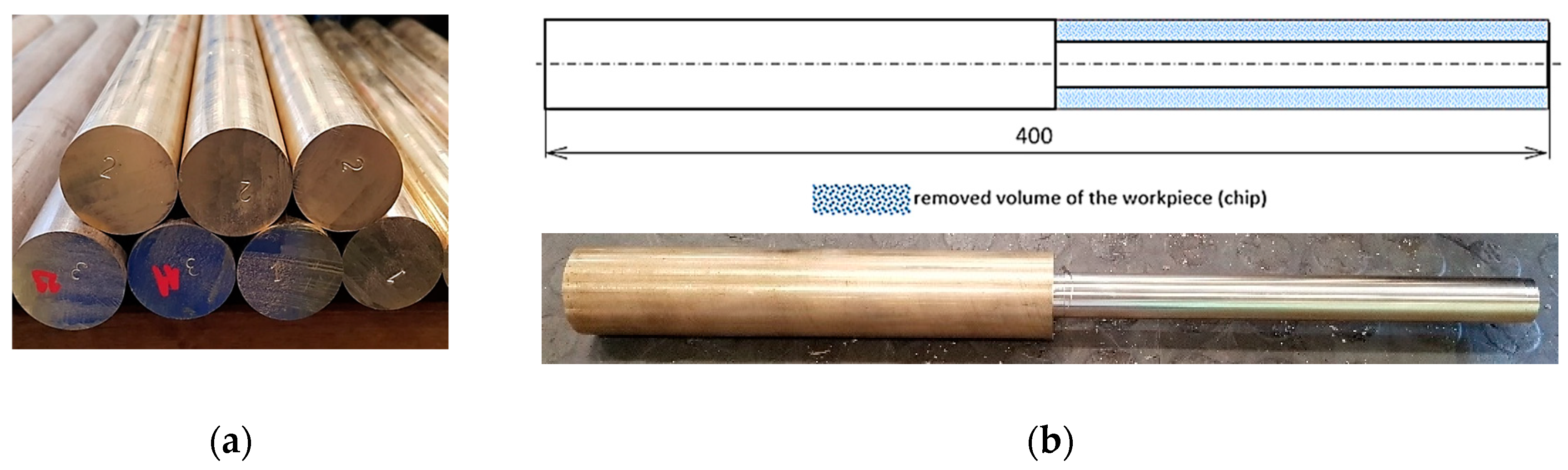
2.1. Machined Materials

Two types of eco-friendly (CW510L and CW724R) and one conventional standard (CW614N) brass alloy were selected as the material to be machined in this study.
Brass alloys are generally characterized by high thermal and electrical properties and conductivity as well as excellent antibacterial properties. Therefore, they are widely used in various industries such as electrical and electronic, automotive, and sanitary. Due to a large number of cutting operations in the production of brass components, various alloying elements improving machinability are usually added to brass. The most important element in this context is lead, which improves machinability due to excellent chip breaking, low tool wear and high usable cutting parameters. These aspects can be explained by two basic phenomena. First, the solubility of lead in brass is very low, and consequently, lead segregation occurs throughout the microstructure, especially at the grain boundaries. This will significantly reduce shear strength, resulting in very good chip breaking. Second, lead exhibits a low melting point Tm = 327.5 °C. During cutting, lead decreases the chip ductility while a thin, semi-liquid lead film reduces friction and thus cutting forces and tool wear [22,23,24,25].
However, since Pb is currently a strongly regulated substance due to environmental and medical concerns, its substitution is of primary importance. Stavroulakis [26] and his team have proposed four directions for further applied research to optimize the design and processing of alloys without lead so as to overcome the characteristics and functionality of conventional lead brass, which meet the requirements of environmental protection, human health and sustainable development.
Brass alloy CW614N is the standard leaded alloy for free cutting purposes, while CW510L and CW724R are lead-free brasses with good machinability, belonging to the group of so-called eco-friendly brass alloys since, for both environmental and health reasons, the reduction of lead in brass parts has great importance [27,28]. The basic characteristics of the brass alloys used in the study are given in Table 1 [29,30,31] and chemical compositions are given in Table 2 [32,33].
The presence of lead (Pb) in conventional leaded brasses (typical composition range ~2.5–3.5 wt%) favors machinability and machining operations, since it results in chip fracturing, enhances lubrication and reduces cutting force minimizing tool wear, see for instance [23,26,32]. It can therefore be said that when replacing the original (leaded) brass with environmentally friendly brass alloys, the conditions of machining deteriorate (due to a decreasing amount of lead), which can virtually directly reduce the productivity of the machining process by reducing technological factors (especially cutting speed and feed) to ensure the required qualitative factors (surface roughness, dimensions) and the efficiency of the process (durability of the cutting tool).
The workpiece was provided in the form of rods with a diameter of 35 mm and a length of 400 mm (Figure 5a). The bar was clamped with a maximum overhang of 200 mm to maintain the required rigidity and before measurements, it was finely machined to a diameter of 34.6 mm. The machined bar after experimental testing is shown in Figure 5b.

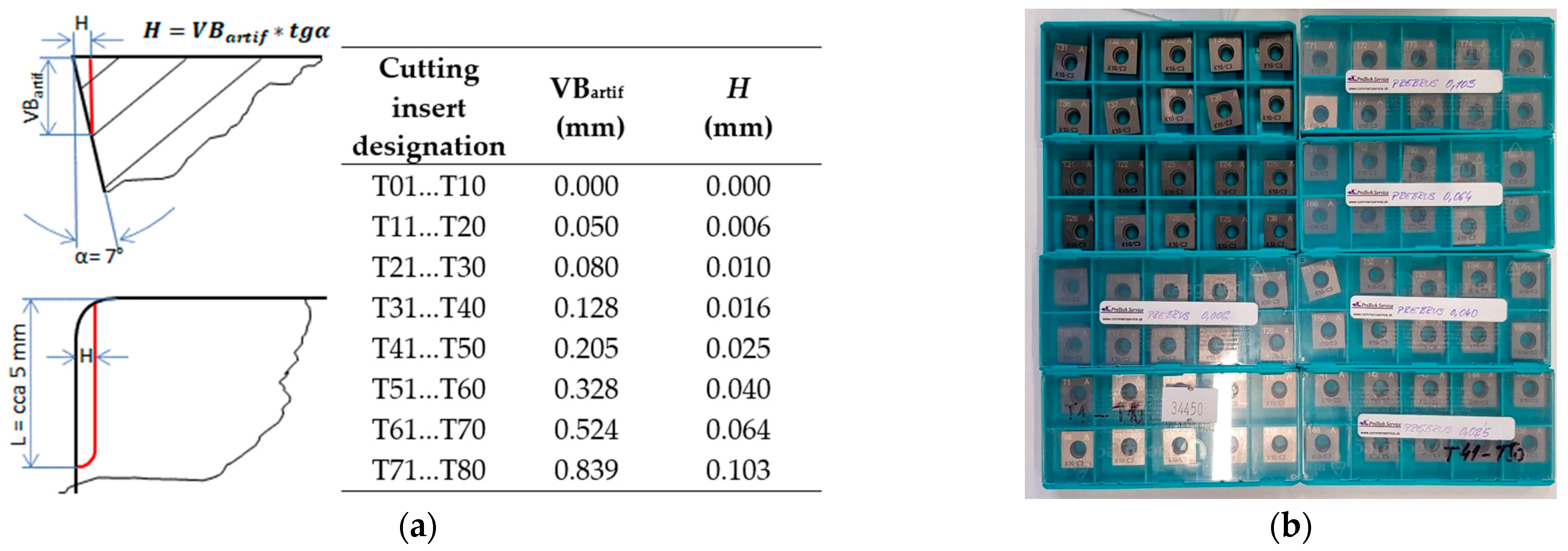
2.2. Machining Process Using the Newly Designed Artificial Wear Methodology

A newly designed methodology was used for the machining of brass alloys based on artificial wear to find out the response of the cutting tool and the whole system to machining under given conditions. The approach was selected because of the existing settings, which were mainly connected to the small diameter of the supplied bars. A diameter of 35 mm is not suitable for long-term testing as it does not enable reaching the desired cutting speed, and when the diameter of the workpiece is becoming smaller, the stiffness of the bar reduces very quickly [33,34,35].
A total of 80 pieces of cutting inserts were specially modified by the experienced supplier, while the artificial tool wear VBartif was created only on the major flank of the tool. A tool wear VB was chosen as the most important factor affecting the quality of the machined surface and the dimensional accuracy of the machined component. The values of artificial wear within the experiments were selected in a geometric series so that they could capture critical values and which are reflected in vibrations. From the point of view of the machined surface, VB = 0.4 mm wear is considered critical during finishing. In the experiment, this range was doubled to better understand the behavior of the machining system and its responses to machining with a worn tool.
At every new test, a cutting tip with a new cutting wedge was used, so one cutting insert was active for four experiments (with different corners). The geometry of created artificial wear VBartif, as well as the values of the VBartif (mm) and grinding depth H (mm) for the individual cutting inserts, are shown in Figure 6a, while prepared cutting inserts are shown in Figure 6b.
Durability evaluation, with a constant cutting depth ap = 1 mm, constant feed f = 0.06 mm, and cutting speeds vc = 100, 150, 225, and 337.5 m/min, was realized according to the relation of diameters to the artificial wears listed in Table 3.
As is seen from Table 3, the tool with the highest wear (0.84 mm) was used for turning the workpiece with the largest diameter (34.6 mm) and the tool with a sharp wedge was used for machining the smallest considered diameter (20.6 mm) to ensure the best possible degree of stability.
ISO 3685 recommendations were used for the maximum extent of geometric and dimensional characteristics of the cutting tool, including working conditions as the basis for settings, given that a similar standard for turning brass alloys with single-point turning tools is not available. The cutting tool consists of a cutting insert (type SCGW 12T304 K10) and a tool holder (type SSBCR 2525 M 12-M-A); the basic characteristics are shown in Table 4. On every machined surface, a new corner of a cutting insert was used.
The universal CNC turning machine DMG MORI ecoTurn 450 was used for experiments. A three-jaw chuck and a rotational tailstock were used for the workpiece clamping and supporting as shown in Figure 7.

2.3. Measurement and Evaluation of Vibration Intensity

A very important accompanying factor of machining is the generation of vibrations. Machining vibrations are forced and self-excited in general. For the safety of the process and the quality of its outputs, it is necessary to monitor self-excited vibrations [36,37].
The self-excitation mechanism in the chip generation during cutting contributes significantly to the characteristic vibrational spectrum of the entire process. Chipping can cause the edge fracture of the machining tool, impairing cutting-edge sharpness and leading to tool blunting. This type of tool failure increased cutting forces, resulting therefore in further degradation of the machining performance (longer chips, higher fluctuations and chattering, part distortion), causing serious defects in the machined surface quality [38,39,40]. The friction on surfaces between the tool and machined material generated a dynamically discontinuous process. Tool wear significantly affects these friction-induced nonlinear vibrations and can be observed through the vibration characteristics of new and worn cutting tools. The evolution of the vibration characteristics can be used for the tool wear progress monitoring, too [41,42,43].
The advantage of installing a system for collecting and evaluating the vibration characteristics of the machining system for monitoring the tool wear process is that it only minimally interferes with the construction of the machine tool and the cutting tool, the monitoring takes place in real time, and this system can also be used to identify the condition of the machine tool.
The assessment of experiments focused on the vibration response analysis was performed in the complex system (Machine tool—Cutting tool—Fixture—Workpiece), therefore the vibration characteristics of the process were examined over a wide range of frequencies (0–25 kHz).
The acceleration sensor Wilcoxon Research WR-712F-M4 was fixed on the bottom of the tool holder, on the opposite side as a cutting insert was attached. The location of the sensor was selected as close as possible to the cutting edge and at the same time in such a way that it was protected from being attacked by chips. A National Instruments PXI-4462 measurement card and LabView software were used to collect and analyze vibration data [44].
An example of a vibro-diagnostics signal in the time domain obtained for one minute of a running machining process is shown in Figure 8. Signals obtained by all measurements were analyzed by the Fast Fourier Transformation (FFT) method. Figure 9 shows the same signal as in Figure 8 but is processed using Fast Fourier Transform (FFT) to observe the measured amplitudes in the frequency domain.
The frequencies at which the peaks occurred are the so-called natural frequencies (indicated in Figure 9 with red crosses). These correspond to the resonant frequencies of the individual elements of the complex machining set, which can seriously influence the overall oscillating properties of the system.
To specify the effect of individual “components” of the machining set on the frequency characteristics and their rigidity, a numerical modal analysis of individual components of the set was performed using the software Ansys 2022 R2. Figure 10 shows a modal analysis of a cutting tool with VBartif = 0.05 mm. (Note: The numerical analysis is not the goal of the presented research, so the authors do not go into detail with the boundary conditions).
Based on the results, it was specified that, e.g., the peak highlighted in Figure 9 as the “Cursor 3” corresponds to the cutting tool, since the first natural frequency of the cutting tool identified by numerical analysis is close to 15,000 Hz (i.e., it was precisely 14,946 Hz for the presented numerical model consisting of the cutting insert and the tool holder, the back planar surface of which was fixed).
A mean value of amplitude as an output of measurement of accelerations was taken into account to evaluate the vibration intensity at the given conditions (specified by the alternate combination of cutting speed and tool wear, and constant parameters cutting depth ap = 1 mm, constant feed f = 0.06 mm).
The measured data were statistically processed using multiple linear regression methodology in this sequence of steps [45,46]:
  • Exclusion of outliers through the Grubbs test;
  • Computing the regression coefficients bi for a linear model with independent variables VBartif and vc and their mutual interaction;
  • Diagnosis of outliers using residuals;
  • Determination of significance of linear regression relationships;
  • Generation of graphical representation of statistically processed data.
An example of the datasheet with processed statistical evaluation of measured data realized in MATLAB software is shown in Figure 11.

2.4. Chip Form Evaluation

The form of the chip created in the cutting process is an essential feature of the process evaluation. The chip form influences mainly [47,48]:
  • The quality of the process—e.g., long-length chips can attack finished surfaces;
  • The stability of the process—e.g., long-length chips do not leave the machine, fill the working space of the machine, and can be wound on a tool or workpiece, and they harm the cutting process itself;
  • The environmental effect of the production—e.g., small, broken chips are far easier to handle, store, transport and recycle.
A very good system of chip form evaluation is given in ISO 3685. The standard classifies the chip form from the following points of view [49]:
  • The first aspect of chip classification consists of the basic characteristics of the chip form:
    (a)
    Shape characteristic (represented by the first number in the classification, e.g., 1—Ribbon, 6—Arc, 7—Elementary);
    (b)
    Chip form extended characteristics (represented by the second number in the classification, e.g., 1—Long, or 2—Short, etc.);
  • The second aspect is the direction of chip movement (represented by the third number within the classification; these can be numbers from 1 to 4, e.g., 1—from the workpiece in the feed direction; etc.).
  • The third aspect is the area on which the chip breaks (represented by the third number within the classification; there can be used numbers from 5 to 8; e.g., 7—broken against the workpiece surface).
Following the above chip form evaluation characteristics, it is possible to state the criteria for the chip form suitability, while several priorities are considered in the criteria statement:
  • Secure required quality characteristics of machined surface;
  • Safety automatic chip removal from the machine tool working area;
  • Efficient chip handling, storage and removal, etc.
The chip form suitability classification scale can be tailored to specific requirements, e.g., Good/Acceptable/Unacceptable, etc.
In order to simplify the above-mentioned chip form evaluation approach by using a binary scale for basic and extended chip form characteristics, for the sake of clarity and a better summary of the characteristics of the created chip, the authors chose to divide the chip form in the final statement into two basic groups:
-
Favorable
-
Unfavorable.
No chip breaker was used for the cutting tool used for evaluation.

3. Results and Discussion

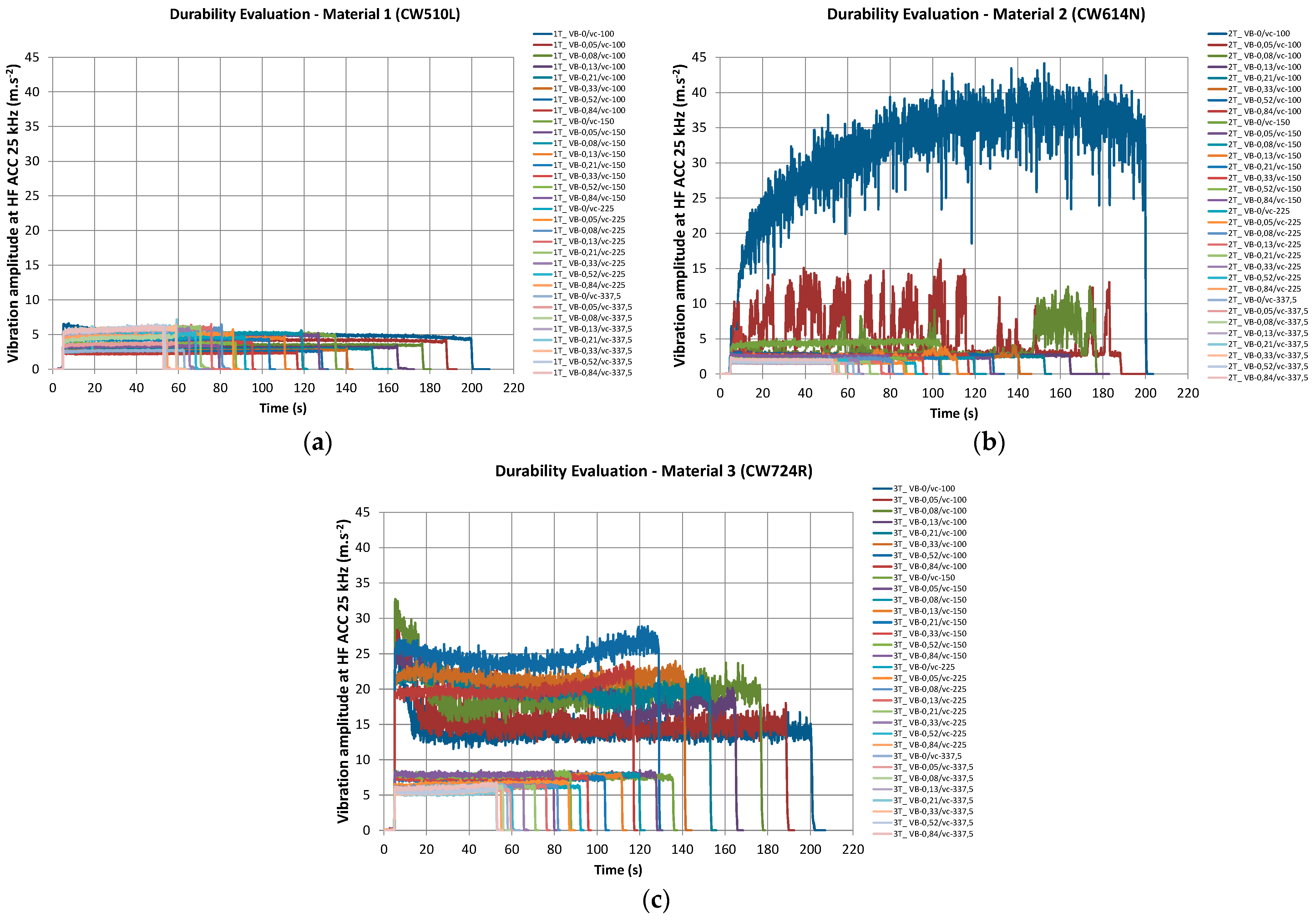
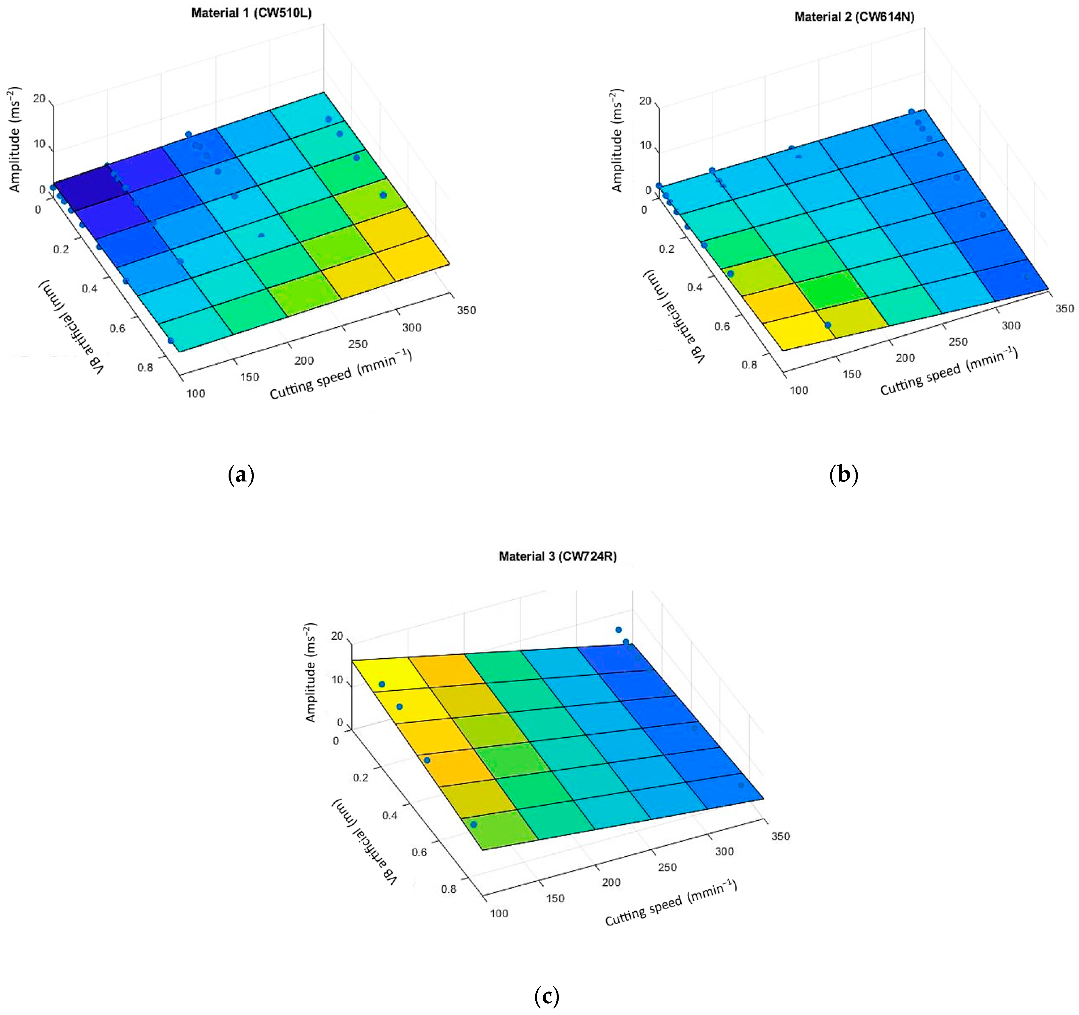
3.1. The Influence of Tool Wear and Cutting Speed on the Intensity of Tool Vibrations

During the vibration measurements, many data were recorded that needed to be processed. Therefore, they had to be studied using several practices and methods related to the phenomena of wear with respect to the chosen scope of cutting speed [50]. The most important analysis focused on increasing the credibility of durability assessment was the determination of the “general intensity of the vibration intensity of the system”. Specification of "intensity" had to take into account the vibro-diagnostic changes of the experimental system to determine the needed machining factors, since any change in spindle rotation (due to the required cutting speeds) considerably affects the frequency range that is interconnected with the tool wear rate and manifested in the machining characteristics [51].
Data recorded during measurements for individual brass alloys are shown in Figure 12.
At first sight, it is clear from the dependencies in Figure 12 that the vibration intensity of the tool is different for each of the three tested materials. The mean value of the vibration intensity under the given conditions was further considered when generating the dependence of the amplitude on wear and cutting speed. A graphical representation of statistically processed data (mesh color surface) is shown in Figure 13.
The results of the vibration amplitude divided the materials into two groups:
  • Material 1 (CW510L) and Material 2 (CW614N) show relatively low sensitivity for generating vibrations through tool wear;
  • Material 3 (CW724R) shows the higher vibration intensity generated by tool wear at lower cutting speeds.
To analyze the behavior of vibrating responses of the machining tool during the turning of individual brass alloys, the following statements can be made.
When machining CW510L brass alloy, the vibration amplitude value increased with wear and the cutting speed increased. This logically expected fact may be attributed to the heterogeneous structure of the material, made of a mixture of alpha and beta phases of the alloy, and the resulting very good value ductility, which is about twice as high as the remaining two compared materials.
From the strength characteristics (Rm/Rp0.2) point of view, this material is at the lowest amplitude values of the materials studied, which certainly contributes to a more suitable force ratio in the chip root and the creation of the lowest cutting resistance. In this case, mechanical properties are very well correlated with the lowest hardness values of all compared materials and the resulting effect on the nature of chip formation and vibration generation. Excellent thermal conductivity is certainly included in the comprehensive action of the external manifestations during machining—which is comparable to the thermal conductivity of the CW614N material but is three times better compared to the CW724R. This gives a prerequisite for better heat distribution to the chips and machined material.
Monitoring of the vibrations during the machining of the CW614N alloy showed that the value of the vibration amplitude increased uniformly with increasing wear on the tool flank area, but decreased with increasing cutting speed. This was probably caused by the duplex microstructure of the material containing insoluble lead particles, which take over the function of reducing the friction of the contact surfaces of the tool and at the same time serve in the place of the cutting plane of the chip as non-cohesive particles, ensuring very good conditions for breaking the chip. The CW614N alloy showed half the ductility value compared to the CW510L material, which indicated its lower plasticity and lower ability to dampen vibrations. From the point of view of strength characteristics (Rm/Rp0.2), the CW614N alloy is at the middle values of the studied materials, which also indicates the middle values of the strength ratios at the root of the chip and the degree of cutting resistance. Even in this case, the mechanical properties were well correlated with the average hardness values of the compared materials and the resulting effect on the character of chip formation and vibration generation. Excellent thermal conductivity, which is comparable to the material CW510L but is three times better compared to the material CW724R, certainly entered into the complex action of external manifestations during machining. This gives the assumption of a better distribution of heat to the chip and the machined material.
From the dependence of vibration intensity of the CW724R brass alloy on the wear and cutting speed it can be seen that the value of the amplitude decreased uniformly with increasing wear on the back surface of the tool and with increasing cutting speed. This resulted from the material’s complex heterogeneous structure in which, compared to other materials, the content of silicon is high. The influence of silicon is manifested mainly by increasing the strength characteristics of brasses, which causes this material to have the highest. In the case of machining, the influence of silicon in the structure is also significant, with considerable grinding action on the tool flank surfaces, and increasing the width of the worn surface as a resulting effect of increasing the damping properties of this frictional contact. The lowest thermal conductivity of the compared materials probably caused a significant increase in temperature in the cutting plane of the chip, thus a substantial increase in local plasticity, and considerably different vibrational manifestations of the machining system.

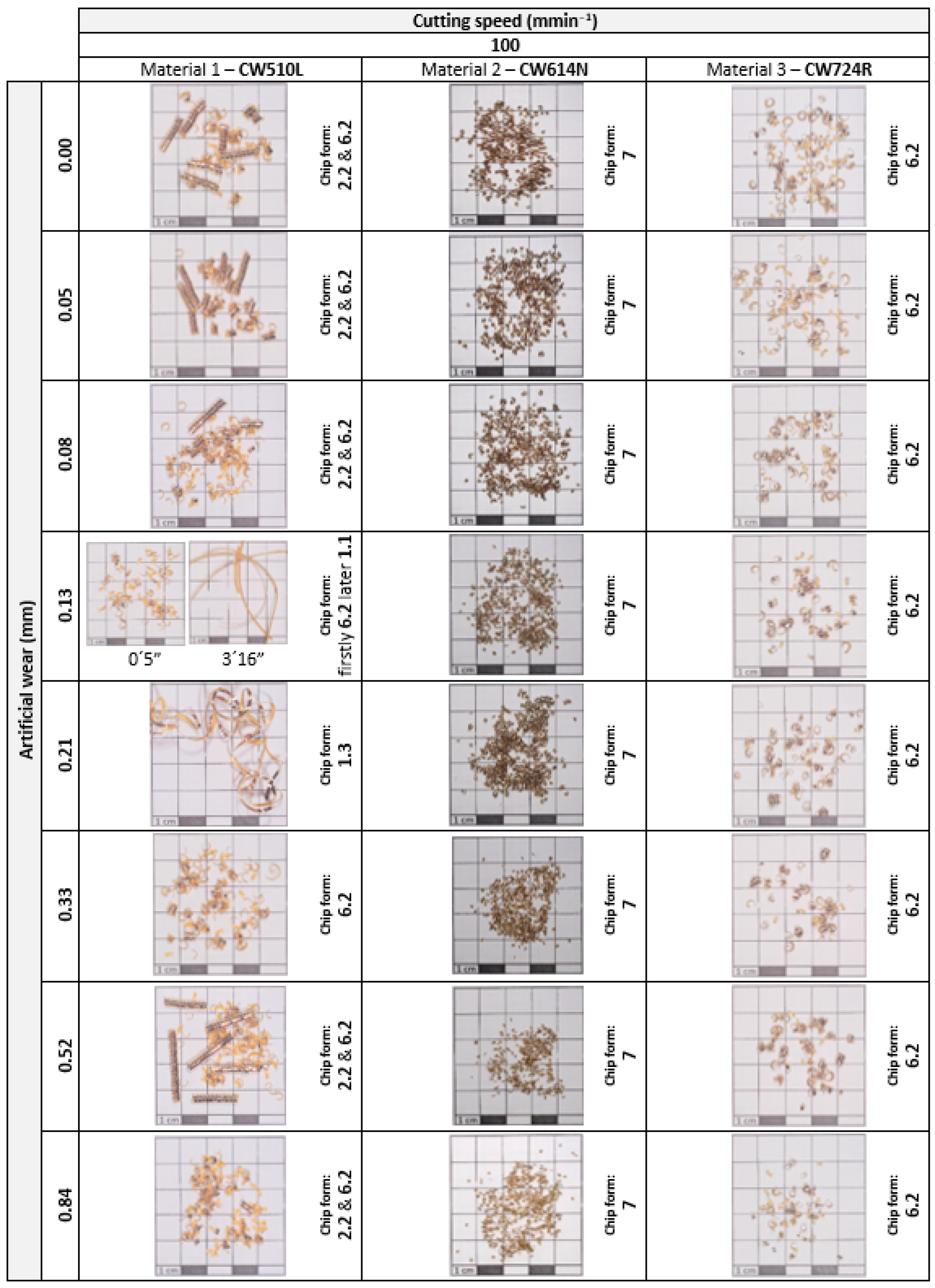
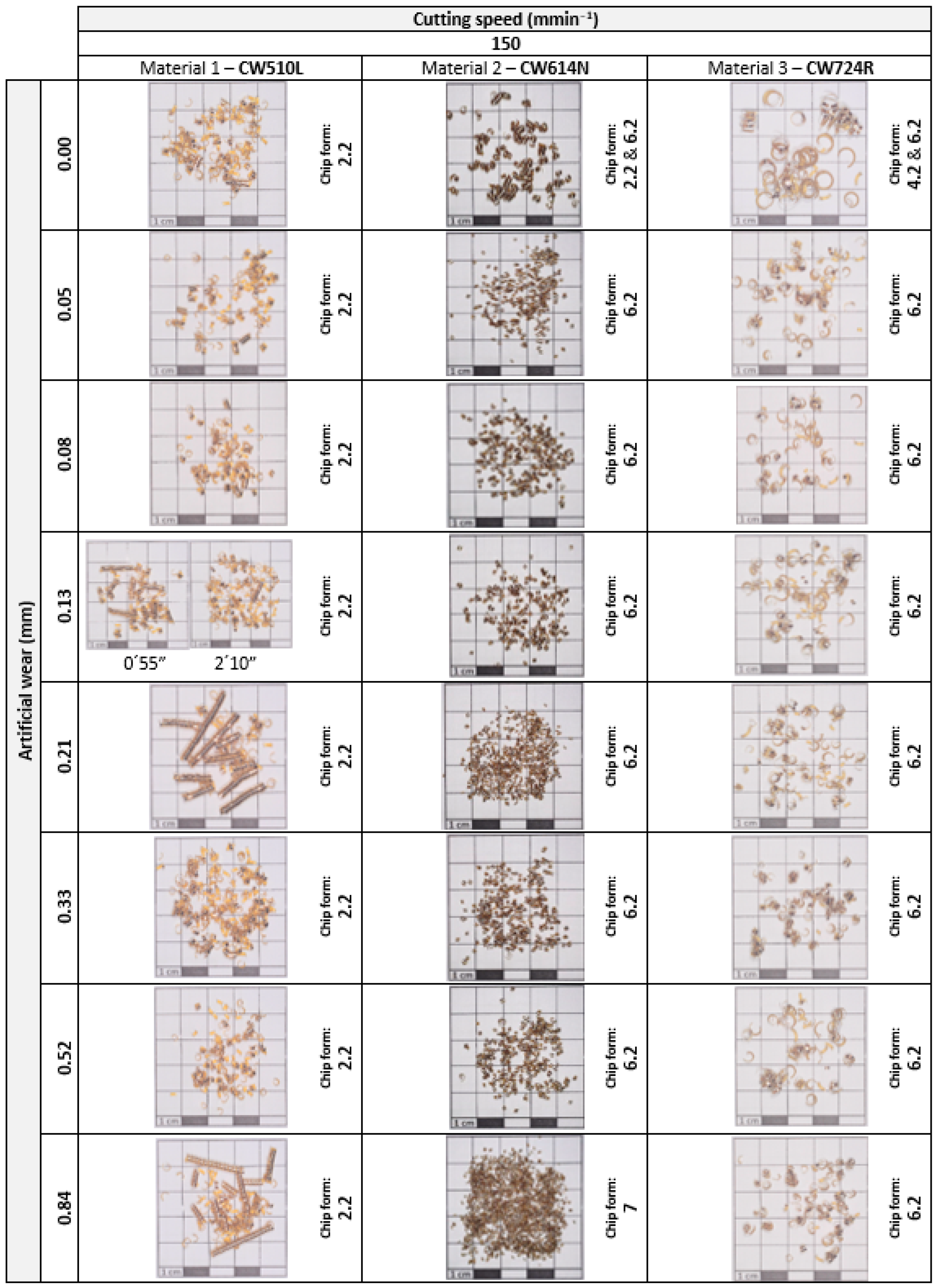
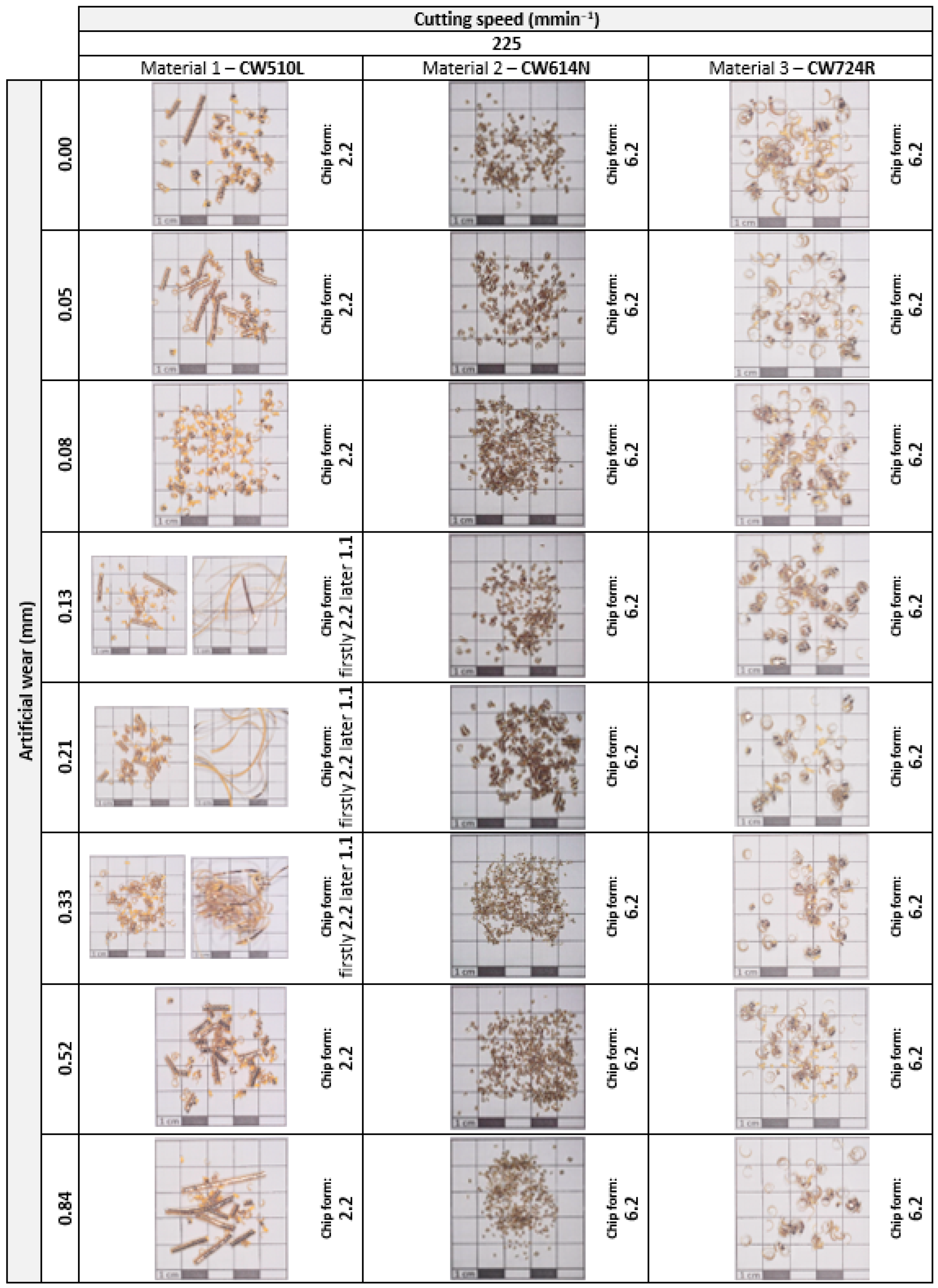
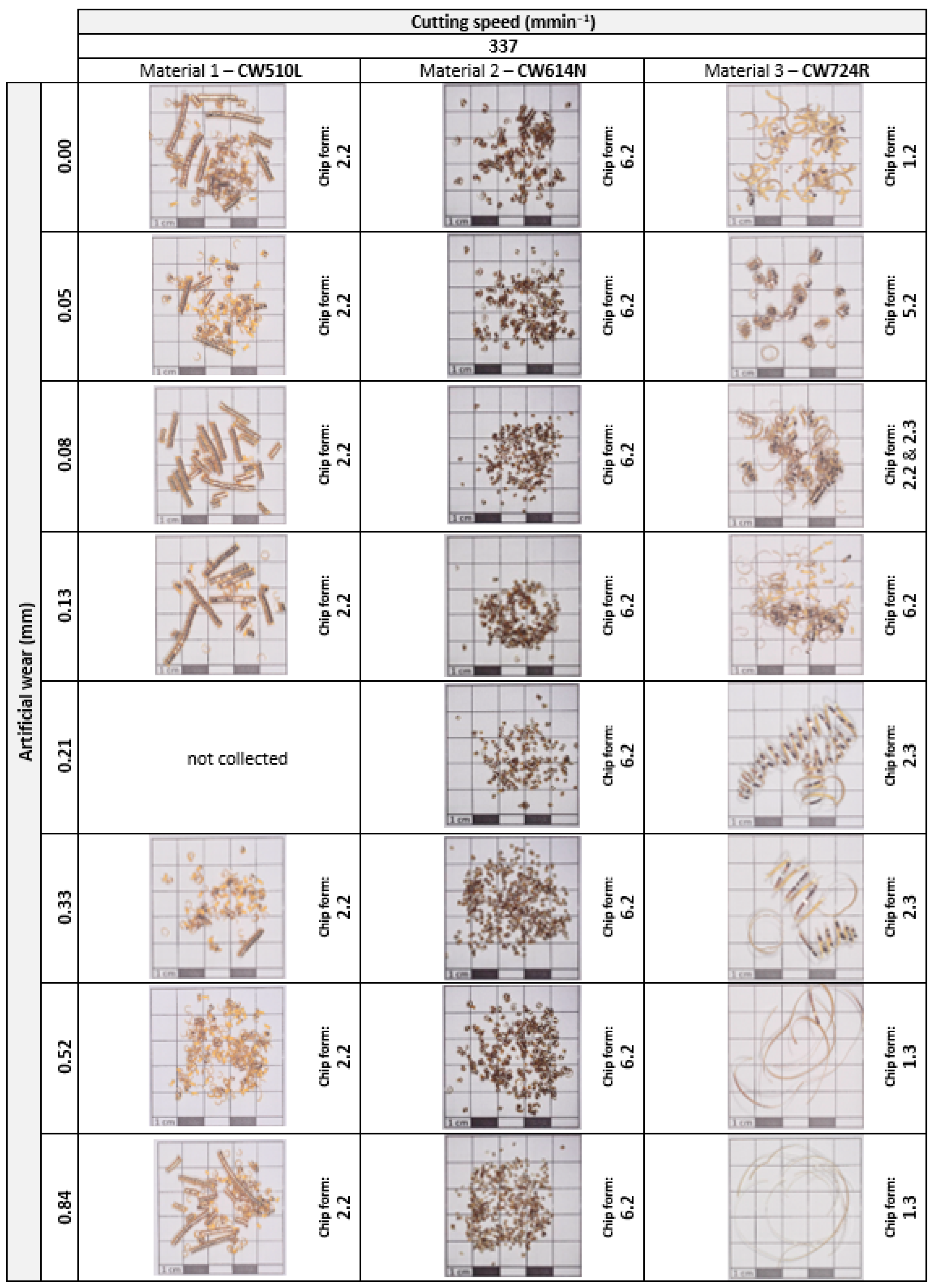
3.2. Evaluation of Chip Form

Waste material from machining (chips, residues) was collected separately for each evaluated group of materials so that it could be recycled and thus ensure a higher degree of environmental protection and non-contamination.
Results of chip evaluation within durability tests are summarized in Figure 14.
It can be stated that the machined brass alloys have shown relatively good chip formation. The problematic chip form occurred only in some cases of Material 1 (CW510L) and Material 3 (CW724R) that is marked in Figure 14 in yellow with the statement “Unfavourable chip form”.
For each combination of machining conditions (given by the type of brass alloy, cutting speed and artificial wear), a representative sample of the removed material was documented in the form of a chip, which was registered and stored in the authors’ internal database. Figure 15, Figure 16, Figure 17 and Figure 18 document the comparison of the resulting forms of chips arising at individual cutting speeds.
From the practical point of view, based on the results related to the chip form originating at the machining of selected brass alloys, it can be said that there are good production conditions in terms of chip shape since it was affected very little by the type of alloy. Undesirable areas of unsuitable chip forms can be easily adjusted by changing the cutting conditions (cutting speed and feed) or—the best practical solution—by using a cutting tool with a chip breaker.

4. Conclusions

Machining is a complex process involving many variables and parameters. In many cases, the theoretically derived dependencies of the basic factors of the cutting process optimization cannot be directly applied in specific production settings, because the boundary conditions (properties of the processed material, product characteristics, machine tool characteristics, process conditions, etc.) in real practice significantly change the expected results. It follows that for each individual system (machine tool, cutting tool, and product), lengthy experimental verification and evaluation would be necessary, which is not possible in practice due to the required high productivity and production efficiency.
A huge disadvantage of the classic approach when creating optimization models is that, despite very precise preparation and processing of experimental results, it is not possible to exclude the occurrence of random events that will significantly shorten the life of some cutting tools and thus cause complications in production. Therefore, in real production conditions, monitoring the response of the system to real stimuli appears to be the most suitable way of monitoring the actual state of the cutting tool, to which the presented research contributes to a large extent.
The primary objective of this research was to determine the level of vibration intensity of machining in response to a particular tool wear while turning brass alloys, and thus determine the level (borderline) at which the process is stable in the newly proposed methodology with an inverse approach that is based on artificially generated tool wear (prepared in advance in advance on the major flank). A supplementary part of the research was the study of chip formation when machining brass alloys in the given machining conditions, as this is directly connected to the wear of the tool. Specifically, the research results can be summarized as follows:
  • The collection and processing of the experimentally obtained data were carried out using the standard steps of the multiple linear regression methodology to evaluate the dependence parameters (vibration characteristic and chip shape characteristic) on the experimental factors (cutting speed and artificial wear VBartif).
  • Based on the measured data, the statistical dependences of the acceleration amplitude (A) as a vibration characteristic on the experimental factors (vc, VBartif) were determined—all at the required level of statistical reliability.
  • CW510L and CW614N brass alloys were found to exhibit an average of three times lower vibration damping compared to CW724R alloy.
  • The CW724R brass alloy showed significantly steeper dependences of vibration generation in terms of changes in cutting speed and VBartif wear compared to the other two materials.
  • Differences in susceptibility to the generation of vibration manifestations are probably caused by the structure of the evaluated materials.
  • The evaluated material production conditions significantly affect the vibro-diagnostic characteristics of the machining process, while for CW510L the slope of the dependence of the amplitude on the cutting speed is opposite to that for the other two materials (with increasing speed, the amplitude grew).
Regarding the evaluation of chip shape properties, it can be concluded:
  • The experiments showed relatively good chip formation in the evaluated machining conditions even without the use of a chip breaker.
  • The problematic chip shape occurred only in some cases with material 1 (CW510L) and material 3 (CW724R), which cannot be generally determined.
  • From the point of view of suitable chip formation, the production conditions were very little affected by the type of alloy.
  • Undesirable areas of inappropriate chip shape can be easily adjusted in practical applications by changing the feed, cutting speed, or—the best practical solution—by using a cutting tool with a chip stiffener optimized for the given process.
In the near future, the authors would like to continue the research with the measurement of cutting forces for the same or for a reduced experimental design.

Author Contributions

Conceptualization, P.P.M., K.M., G.A.P. and A.I.T.; methodology, P.P.M. and K.M.; software, P.P.M. and K.M.; validation, P.P.M., K.M. and G.A.P.; formal analysis, A.I.T.; investigation, P.P.M. and K.M.; resources, P.P.M., K.M. and A.I.T.; data curation, K.M., P.P.M. and A.I.T.; writing—original draft preparation, K.M.; writing—review and editing, P.P.M. and G.A.P.; visualization, K.M., P.P.M. and G.A.P.; supervision, P.P.M. and G.A.P.; project administration, K.M. and G.A.P.; funding acquisition, K.M., P.P.M. and G.A.P. All authors have read and agreed to the published version of the manuscript.

Funding

This research was funded by the Ministry of Education, Science, Research and Sport of the Slovak Republic by grants APVV-19-0550, KEGA 005TUKE-4/2021, KEGA 032TUKE-4/2022, and SK-CN-21-0046 as well as by ELKEME S.A.

Data Availability Statement

Not applicable.

Acknowledgments

The support and encouragement of ELKEME S.A. management and ELVALHALCOR Brass Rods and Tubes Plant are greatly appreciated. The article was prepared thanks to the support of the Ministry of Education, Science, Research and Sport of the Slovak Republic through the grants APVV-19-0550, KEGA 005TUKE-4/2021, KEGA 032TUKE-4/2022 and SK-CN-21-0046.

Conflicts of Interest

The authors declare no conflict of interest.

References

  1. Grzesik, W. Advanced Machining Processes of Metallic Materials—Theory, Modelling and Applications; Elsevier: Amsterdam, The Netherlands, 2017; ISBN 978-0-444-63711-6. [Google Scholar]
  2. Trent, E.M.; Wright, P.K. Metal Cutting: Theory and Application; Butterwort Heinemann: Auckland, New Zealand, 2000; ISBN 0-7506-7069-X. [Google Scholar]
  3. Jurko, J.; Panda, A.; Behun, M. Prediction of a new form of the cutting tool according to achieve the desired surface quality. Appl. Mech. Mater. 2013, 268–270, 473–476. [Google Scholar] [CrossRef]
  4. Suh, C.S.; Liu, M.-K. Control of Cutting Vibration and Machining Instability: A Time-Frequency Approach for Precision, Micro and Nano Machining; John Wiley & Sons: Chichester, UK, 2013; ISBN 978-1-118-37182-4. [Google Scholar]
  5. Kuyucak, S.; Sahoo, M. A review of the machinability of copper-base alloys. Can. Metall. Q. 1996, 35, 1–15. [Google Scholar] [CrossRef]
  6. Jerzy, J.; Kuric, I.; Grozav, S.; Ceclan, V. Diagnostics of CNC machine tool with R-Test system. Acad. J. Manuf. Eng. 2014, 12, 56–60. [Google Scholar]
  7. Pitel, J.; Matiskova, D.; Marasova, D. A new approach to evaluation of the material cutting using the artificial neural networks. TEM J. 2019, 8, 325–332. [Google Scholar]
  8. Markopoulos, A.P.; Pressas, I.S.; Papantoniou, I.G.; Karkalos, N.E.; Davim, J.P. Machining and machining modeling of metal matrix composites—A review. In Modern Manufacturing Engineering; Springer: Cham, Switzerland, 2015; pp. 99–141. [Google Scholar]
  9. Twardowski, P.; Legutko, S.; Krolczyk, G.M.; Hloch, S. Investigation of wear and tool life of coated carbide and cubic boron nitride cutting tools in high speed milling. Adv. Mech. Eng. 2015, 7, 1687814015590216. [Google Scholar] [CrossRef]
  10. Petru, J.; Schiffner, J.; Zlamal, T.; Cep, R.; Kratochvil, J.; Stancekova, D. Wear progress of exchangeable cutting inserts during Ti (6) Al (4) V alloy machining. In Proceedings of the 24th International Conference on Metallurgy and Materials, Brno, Czech Republic, 3–5 June 2015; pp. 1147–1155. [Google Scholar]
  11. Stavropoulos, P.; Papacharalampopoulos, A.; Vasiliadis, E.; Chryssolouris, G. Tool wear predictability estimation in milling based on multi-sensorial data. Int. J. Adv. Manuf. Technol. 2016, 82, 509–521. [Google Scholar] [CrossRef]
  12. Zetek, M.; Zetkova, I. Increasing of the cutting tool efficiency from tool steel by using fluidization method. Procedia Eng. 2015, 100, 912–917. [Google Scholar] [CrossRef]
  13. Bakša, T.; Kroupa, T.; Hanzl, P.; Zetek, M. Durability of cutting tools during machining of very hard and solid materials. Procedia Eng. 2015, 100, 1414–1423. [Google Scholar] [CrossRef]
  14. Dimla, D.E. The Correlation of Vibration Signal Features to Cutting Tool Wear in a Metal Turning Operation. Int. J. Adv. Manuf. Technol. 2002, 19, 705–713. [Google Scholar] [CrossRef]
  15. Xu, C.; Jianming, D.; Yuzhen, C.; Huaiyuan, L.; Zhicheng, S.; Jing, X. The relationships between cutting parameters, tool wear, cutting force and vibration. Adv. Mech. Eng. 2018, 10, 1687814017750434. [Google Scholar] [CrossRef]
  16. Bouhalais, M.L.; Nouioua, M. The analysis of tool vibration signals by spectral kurtosis and ICEEMDAN modes energy for insert wear monitoring in turning operation. Int. J. Adv. Manuf. Technol. 2021, 115, 2989–3001. [Google Scholar] [CrossRef]
  17. Sridhar, A.V.; Prasad, B.S.; Mouli, K.V. Evaluation of tool performance and wear through vibration signature analysis in drilling of IS3048 steel. J. Eng. Appl. Sci. 2021, 68, 27. [Google Scholar] [CrossRef]
  18. Babu, M.S.; Rao, T.B. Real-time cutting tool condition assessment and stochastic tool life predictive models for tool reliability estimation by in-process cutting tool vibration monitoring. Int. J. Interact. Des. Manuf. 2022, 1–17. [Google Scholar] [CrossRef]
  19. Antić, A.; Šimunović, G.; Šarić, T.; Milošević, M.; Ficko, M. A model of tool wear monitoring system for turning. Tech. Gaz. 2013, 20, 247–254. [Google Scholar]
  20. Childs, T.; Maekawa, K.; Obikawa, T. Metal Machining: Theory and Applications; Butterworth-Heinemann: London, UK, 2000; ISBN 0-340-69159-X. [Google Scholar]
  21. Pastucha, P.; Majstorovic, V.; Kučera, M.; Beno, P.; Krile, S. Study of Cutting Tool Durability at a Short-Term Discontinuous Turning Test. In Proceedings of the International Conference on Manufacturing Engineering and Materials (ICMEM 2018), Novy Smokovec, Slovakia, 18–22 June 2018; pp. 493–501. [Google Scholar] [CrossRef]
  22. Toulfatzis, A.I.; Pantazopoulos, G.A.; David, C.N.; Sagris, D.S.; Paipetis, A.S. Machinability of eco-friendly lead-free brass alloys: Cutting-force and surface-roughness optimization. Metals 2018, 8, 250. [Google Scholar] [CrossRef]
  23. Pantazopoulos, G. Leaded brass rods C38500 for automatic machining operations. J. Mater. Eng. Perform. 2002, 11, 402–407. [Google Scholar] [CrossRef]
  24. Gane, N. The effect of lead on the friction and machining of brass. Philos. Mag. 1981, 43, 545–566. [Google Scholar] [CrossRef]
  25. Nobel, C.; Klocke, F.; Lung, D.; Wolf, S. Machinability Enhancement of Lead-free Brass Alloys. Procedia CIRP 2014, 14, 95–100. [Google Scholar] [CrossRef]
  26. Stavroulakis, P.; Toulfatzis, A.I.; Pantazopoulos, G.A.; Paipetis, A.S. Machinable Leaded and Eco-Friendly Brass Alloys for High Performance Manufacturing Processes: A Critical Review. Metals 2022, 12, 246. [Google Scholar] [CrossRef]
  27. Toulfatzis, A.; Pantazopoulos, G.; Paipetis, A. Fracture behavior and characterization of lead-free brass alloys for machining applications. J. Mater. Eng. Perform. 2014, 23, 3193–3206. [Google Scholar] [CrossRef]
  28. Johansson, J.; Alm, P.; M’Saoubi, R.; Malmberg, P.; Ståhl, J.-E.; Bushlya, V. On the Function of Lead (Pb) in Machining Brass Alloys. Res. Sq. 2022, 120, 7263–7275. [Google Scholar] [CrossRef]
  29. Company Sarbak Materials Data Sheets. Available online: www.sarbak.com.tr (accessed on 19 June 2022).
  30. EN 1982; Copper and Copper Alloys—Ingots and Castings. CEN: Brussels, Belgium, 2017.
  31. EN 12164; Copper and Copper Alloys—Rod for Free Machining Purposes. CEN: Brussels, Belgium, 2016.
  32. Pantazopoulos, G.; Vazdirvanidis, A. Characterization of the microstructural aspects of machinable? Phase brass. Microsc. Anal. 2008, 22, 13–16. [Google Scholar]
  33. Toulfatzis, A.I.; Pantazopoulos, G.A.; Paipetis, A.S. Fracture mechanics properties and failure mechanisms of environmental-friendly brass alloys under impact, cyclic and monotonic loading conditions. Eng. Fail. Anal. 2018, 90, 497–517. [Google Scholar] [CrossRef]
  34. Garcia, P.; Rivera, S.; Palacios, M.; Belzunce, J. Comparative study of the parameters influencing the machinability of leaded brasses. Eng. Fail. Anal. 2010, 17, 771–776. [Google Scholar] [CrossRef]
  35. Filippov, A.V.; Filippova, E.O. Determination of cutting forces in oblique cutting. Appl. Mech. Mater. 2015, 756, 659–664. [Google Scholar] [CrossRef]
  36. Altintas, Y. Manufacturing automation: Metal cutting mechanics, machine tool vibrations, and CNC design. Appl. Mech. Rev. 2012, 54, B84. [Google Scholar]
  37. Vazdirvanidis, A.; Rikos, A.; Toulfatzis, A.I.; Pantazopoulos, G.A. Electron Backscatter Diffraction (EBSD) Analysis of Machinable Lead-Free Brass Alloys: Connecting Texture with Fracture. Metals 2022, 12, 569. [Google Scholar] [CrossRef]
  38. Hagarová, M.; Peterka, P.; Mantič, M.; Vojtko, M.; Baranová, G.; Matvija, M. Failure analysis of leaded brass bolt. Eng. Fail. Anal. 2023, 143, 106899. [Google Scholar] [CrossRef]
  39. Toulfatzis, A.I.; Besseris, G.J.; Pantazopoulos, G.A.; Stergiou, C. Characterization and comparative machinability investigation of extruded and drawn copper alloys using non-parametric multi-response optimization and orthogonal arrays. Int. J. Adv. Manuf. Technol. 2011, 57, 811–826. [Google Scholar] [CrossRef]
  40. Yaqoob, K.; Hashmi, F.; Hassan Tanvir, W. Failure Analysis of Cartridge Brass Shell. Eng. Fail. Anal. 2022, 138, 106325. [Google Scholar] [CrossRef]
  41. Baron, P.; Dobransky, J.; Pollak, M.; Kocisko, M.; Cmorej, T. The parameter correlation of acoustic emission and high-frequency vibrations in the assessment process of the operating state of the technical system. Acta Mech. Autom. 2016, 10, 112–116. [Google Scholar] [CrossRef]
  42. Filippov, A.V.; Nikonov, A.Y.; Rubtsov, V.E.; Dmitriev, A.I.; Tarasov, S.Y. Vibration and acoustic emission monitoring the stability of peakless tool turning: Experiment and modeling. J. Mater. Process. Technol. 2017, 246, 224–234. [Google Scholar] [CrossRef]
  43. Chen, J.; Feng, J.; Wang, F.; Peng, Q.; Lan, G.; Zhao, L.; Wu, L. Cracking Analysis of a Brass Clamp Mounted on the Main Transformer in the Power Grid System. Energies 2023, 16, 3460. [Google Scholar] [CrossRef]
  44. Monka, P.P.; Monkova, K.; Pantazopoulos, G.; Toulfatzis, A.I. Effect of Wear on the Vibrating Behaviour of the Tool at Turning CW724R Alloy. In Proceedings of the 13th International Conference on Mechanical and Aerospace Engineering (ICMAE), Bratislava, Slovakia, 20–22 July 2022; pp. 51–55. [Google Scholar] [CrossRef]
  45. Panda, A.; Dobránsky, J.; Jančík, M.; Pandova, I.; Kačalová, M. Advantages and effectiveness of the powder metallurgy in manufacturing technologies. Metalurgija 2018, 57, 353–356. [Google Scholar]
  46. Obeng, D.P.; Morrell, S.; Napier-Munn, T.J. Application of central composite rotatable design to modeling the effect of some operating variables on the performance of the three-product cyclone. Int. J. Miner. Process. 2005, 76, 181–192. [Google Scholar] [CrossRef]
  47. Malotova, S.; Cep, R.; Cepova, L.; Petru, J.; Stancekova, D.; Kyncl, L.; Hatala, M. Roughness Evaluation of the Machined Surface at Interrupted Cutting Process. Manuf. Technol. 2016, 16, 168–173. [Google Scholar] [CrossRef]
  48. Kouadri, S.; Necib, K.; Atlati, S.; Haddag, B.; Nouari, M. Quantification of the chip segmentation in metal machining: Application to machining the aeronautical aluminum alloy AA2024-T351 with cemented carbide tools WC-Co. Int. J. Mach. Tools Manuf. 2013, 64, 102–113. [Google Scholar] [CrossRef]
  49. ISO 3685: 1993(E); International Standard, Tool Testing with Single Point Turning Tools. ISO: Geneva, Switzerland, 1993.
  50. Sahraoui, Z.; Mehdi, K.; Jaber, M.B. Analytical and experimental stability analysis of AU4G1 thin-walled tubular workpieces in turning process. Proc. Inst. Mech. Eng. Part B J. Eng. Manuf. 2020, 234, 1007–1018. [Google Scholar] [CrossRef]
  51. Glaa, N.; Mehdi, K.; Moussaoui, K.; Zitoune, R. Numerical and experimental study of the drilling of multi-stacks made of titanium alloy Ti-6Al-4V: Interface and burr behaviour. Int. J. Adv. Manuf. Technol. 2020, 107, 1153–1162. [Google Scholar] [CrossRef]
Figure 1. Influence of cutting parameters on tool life: (a) ap—depth of cut, (b) f—feed, (c) vc—cutting speed.
Metals 13 00828 g001
Figure 2. Regularities of the (a) cutting tool degradation and (b) removal rate—depending on the temperature at the point of the cut.
Metals 13 00828 g002
Figure 3. Optimal wear of the cutting tool—uniform flank wear.
Metals 13 00828 g003
Figure 4. (a) Taylor tool-life curve, (log-log scale); (b) The wear and failure criteria for carbide inserts.
Metals 13 00828 g004
Figure 5. Workpiece (a) rods provided by the supplier; (b) machined part.
Metals 13 00828 g005
Figure 6. (a) Geometrical and dimensional characteristics of artificial wear; (b) Cutting inserts with prepared artificial wear.
Metals 13 00828 g006
Figure 7. Positions of the individual items of the machining set.
Metals 13 00828 g007
Figure 8. Example of signal collected for the evaluation process (time domain).
Metals 13 00828 g008
Figure 9. Example of the signal in the frequency domain processed using Fast Fourier Transformation.
Metals 13 00828 g009
Figure 10. Numerical modal analysis of the cutting tool.
Metals 13 00828 g010
Figure 11. The example of a datasheet with statistical evaluation of measured data.
Metals 13 00828 g011
Figure 12. Measured vibrations in a time domain for individual materials; (a) CW510L; (b) CW614N; (c) CW724R.
Metals 13 00828 g012
Figure 13. Graphical interpretation of vibration relationship on cutting speed and artificial tool wear for individual materials; (a) CW510L; (b) CW614N; (c) CW724R.
Metals 13 00828 g013
Figure 14. Evaluation of chip form produced during experimental verification.
Metals 13 00828 g014
Figure 15. Comparison of chips originated at cutting speed 100 m/min.
Metals 13 00828 g015
Figure 16. Comparison of chips originated at cutting speed 150 m/min.
Metals 13 00828 g016
Figure 17. Comparison of chips originated at cutting speed 225 m/min.
Metals 13 00828 g017
Figure 18. Comparison of chips originated at cutting speed 337.5 m/min.
Metals 13 00828 g018
Table 1. Basic characteristics of machined brass alloys data from [29,30,31].
CharacteristicUnitCW510L
(Material 1)
CW614N
(Material 2)
CW724R
(Material 3)
Tensile strength Rm(MPa)478–484 [25]
220–500 [28] *
456 [25]
360–500 [28] *
654 [25]
500–670 [28] *
Yield strength Rp0.2(MPa)310–315 [25]324 [25]400 [25]
HardnessHB134–157 [25]
90–160 [28] *
154 [25]
90–160 [10] *
210 [25]
130–220 [28] *
Elongation to break A(%)25–29 [25]
5–20 [28] *
26 [25]
5–20 [28] *
21 [25]
10–15 [28] *
Thermal conductivity λ(W/mK)113–139 [25]
139 [28]
123 [25]
113 [28]
35 [25]
35 [28]
* Depending on the method of production.
Table 2. Indicative chemical compositions of machined brass alloys (wt%) data from [32,33].
CuZnPbSiAsP
CW510L (Material 1)57.38420.07---
CW614N (Material 2)57.61393.32---
CW724R (Material 3)75.86210.023.4-0.05
Table 3. Relation of artificial wear and the workpiece diameters used in machining.
Range of the Workpiece Diameters (mm)VBartif (mm)
34.6–32.60.84
32.6–30.60.52
30.6–28.60.33
28.6–26.60.21
26.6–24.60.13
24.6–22.60.08
22.6–20.60.05
20.6–18.60.00
Table 4. Geometrical and dimensional characteristics of the cutting tool.
Geometrical and Dimensional CharacteristicValue
Cutting insert
Rake angle γ
Clearance angle α
Cutting edge inclination angle λs
Tool cutting edge angle κr75°
Tool included angle εr90°
Corner radius rε0.4 mm
Tool holder
Tool cross-section25 × 25 mm
Insert shapeSquare
Insert size12.7 mm
Insert thickness3.18 mm
Disclaimer/Publisher’s Note: The statements, opinions and data contained in all publications are solely those of the individual author(s) and contributor(s) and not of MDPI and/or the editor(s). MDPI and/or the editor(s) disclaim responsibility for any injury to people or property resulting from any ideas, methods, instructions or products referred to in the content.

