Article

Process and Mechanism of Sealing 65 vol.% SiCp/ZL102 Composite and DM305 Electronic Glass with Borosilicate Glass

1
School of Materials Science and Engineering, Henan Polytechnic University, Jiaozuo 454000, China
2
State Key Laboratory of Advanced Welding and Joining, Harbin Institute of Technology, Harbin 150001, China
3
Henan Jingtai High-Novel Materials Ltd. of Science and Technology, Jiaozuo 454000, China
*
Author to whom correspondence should be addressed.
Metals 2023, 13(4), 817; https://doi.org/10.3390/met13040817
Submission received: 28 March 2023 / Revised: 15 April 2023 / Accepted: 19 April 2023 / Published: 21 April 2023
(This article belongs to the Section Welding and Joining)

Abstract

:
SiC-particulate-reinforced aluminum matrix composites (SiCp/Al MMCs) are widely used in the aerospace field due to their high specific stiffness and strength, low thermal expansion coefficient, and good radiation resistance. In the process of application and promotion, there is a connection problem between the aluminum matrix composites and electronic glass. In this work, the lead-free SiO2-B2O3-Na2O glass filler was used to seal 65 vol.% SiCp/ZL102 composites and DM305 electronic glass in an atmospheric environment. The effects of the sealing temperature on the properties of the joints were studied by scanning electron microscopy (SEM) and energy dispersive X-ray spectroscopy (EDS). Additionally, the causes of defects and the fracture mechanisms of the joints were analyzed. The results showed that the glass filler and base material were connected through a dual mechanism of an Al, Na, Si, and O element diffusion reaction and a mechanical occlusion. At a sealing temperature of 540 °C and a holding time of 30 min, the joint interface was dense and crack-free. Meanwhile, the average shear strength reached 13.0 MPa, and the leakage rate of air tightness was 1 × 10⁻⁹ Pa·m3/s. The brittle fracture features were revealed by the step-like morphology of the fracture, which originated from the brazing seam and propagated into the pore. The crack gradually propagated into the base material on both sides as the fracture area expanded, ultimately resulting in a fracture.

1. Introduction

Glass–metal seals have the characteristics of corrosion resistance, insulation, and oxidation resistance from the glass, as well as excellent thermal conductivity, plasticity, and toughness from the metal [1,2,3,4]. Additionally, they have been widely used in various fields such as microelectronic packaging, solid-oxide fuel cells (SOFCs), and solar vacuum tubes [5,6,7]. However, due to the differences in the structure and properties of glass and metal, the following three issues need to be considered in the process of connecting glass and metal [8]: (i) the wettability between the interfaces of dissimilar materials; (ii) the residual stress of joints; and (iii) the interface reactions between the glass and metal. Additionally, the current methods for connecting glass and metal include anodic bonding [9], laser welding [10], brazing [11], etc.
Chen [12] successfully accomplished anodic bonding between sodium borosilicate glass and Kovar alloy. The results showed that the alkali metal ions in the glass migrated from the anode to the cathode under the action of the electric field, and an alkali metal ion depletion layer was formed in the glass matrix near the interface. The average shear strength of the bonded sample joint was 8–12 MPa. Feng [13] et al., utilized anodic bonding technology to achieve the connection between glass and copper. The research results showed that the Na poor layer formed on the glass surface was key to realize the bonding between glass and copper. In addition, when the bonding voltage was 1400 V and the bonding temperature was 400 °C, the glass and copper formed a close bond with a maximum shear strength of 11.5 MPa. Utsumi [14] connected glass with metal and irradiated the metal surface with a short pulse laser through the glass to directly bond them together. The maximum shear strength of the bond was 690 kPa when the sample was irradiated twice at a pulse energy of 300 μJ. Ji [15] et al., welded soda lime glass and Kovar alloy using an FS laser. They found that the joint had good water resistance and sealing performance, although the joint bonding strength was only 2 MPa. While anodic bonding offers advantages in terms of low temperature and bonding time, it necessitates remarkably low sample surface roughness. Laser welding, on the other hand, exhibits a low bonding strength and is unsuitable for connecting intricate structural components. Consequently, the two methods are not appropriate for large-scale industrial production. However, brazing offers the advantages of a simple process, wide applicability, and high connection strength, making it the favored method for electronic packaging. Xu [16] et al., studied the wettability and interfacial bonding mechanism of 55 vol.% SiCp/Al composites sealed with PbO-ZnO-B2O3 glass. The results showed that the wetting ability of glass on the surface of the base metal increased with the increase in temperature. In addition, joint bonding was caused by Pb and Al element diffusion. Chu [17] et al., successfully achieved the direct, low-temperature brazing of 65 vol.% SiCp/6063Al composites and DM305 electronic glass using a PbO-SiO2-ZnO composite glass brazing filler in an atmospheric environment. When the brazing temperature was 480 °C and the holding time was 30 min, the maximum shear strength was 7.16 MPa, and the air tightness met the requirements of general electronic packaging. However, the glass powder contained Pb, which had a negative impact on the environment. Wang [18] et al., reported the use of a Bi2O3-ZnO-B2O3 lead-free glass solder for the low-temperature sealing of Kovar alloy and DM305 electronic glass in air. The main sealing mechanism was caused by the diffusion of the Bi element in the glass solder. At a sealing temperature of 500 °C and a holding time of 20 min, the highest shear strength obtained was 12.24 MPa.
High-volume-fraction SiC particle-reinforced aluminum matrix composites (SiCp/Al MMCs) are considered potential materials for third-generation active-phased array radar T/R module packaging due to their high specific stiffnesses and strengths, low thermal expansion coefficients, and good radiation resistances [19,20,21,22]. In the process of the popularization and application of the composite, it is inevitable to encounter the key problem of the connection between aluminum matrix composites and DM305 glass. On the one hand, the surface of 65 vol.% SiCp/ZL102 composites is easily oxidized to Al2O3, and the content of SiC on the composite’s surface is high; thus, the surface chemical bond type is similar to the glass [23]. On the other hand, the chemical composition of DM305 electronic glass is borosilicate glass. In view of the above two reasons, lead-free SiO2-B2O3-ZnO-Na2O glass powder was used as a filler to seal 65 vol.% SiCp/ZL102 composites and DM305 electronic glass in an atmospheric environment. The microstructure and sealing properties of the sealing joints were characterized by scanning electron microscopy and mechanical property testing. The optimal sealing temperature was explored, and the connection mechanism of SiO2-B2O3-ZnO-Na2O glass with 65 vol.% SiCp/ZL102 composites and DM305 electronic glass was analyzed, providing theoretical support for the application of the glass filler in the field of sealing with aluminum matrix composites.

2. Materials and Methods

The 65 vol.% SiCp/ZL102 composites were provided by Hunan Haoweite Technology Development Co., Ltd. (Changsha, China), with the size of 20 × 10 × 2 mm. The scanning electron microscope image of the composite is shown in Figure 1. The DM305 electronic glass was provided by Jiangsu Yafei Special Glass Co., Ltd. (Lianyungang, China) of a size of 20 × 10 × 2 mm. In addition, the ZL102 is an aluminum–silicon alloy, and the DM305 is a borosilicate glass. The chemical composition of the ZL102 alloy and DM305 glass are shown in Table 1 and Table 2. In this research, a paste glass filler (2:1 borosilicate glass powder and terpineol mix) was used as the filler. The chemical composition of borosilicate glass was SiO2-B2O3-ZnO-NaO2. The coefficients of thermal expansion (CTE) of the 65 vol.% SiCp/ZL102 DM305 electronic glass and glass filler used in this work at 0~300 °C are shown in Table 3.
Before the sealing test, the base metal was pretreated. The DM305 glass was ultrasonically cleaned with an alcohol acetone solution and dried. For the pre-treatment of the 65 vol.% SiCp/ZL102 composites, the specific process flow is as follows. First, the surfaces of the composites were polished with 600 # SiC sandpaper and ultrasonically cleaned with an alcohol solution. Then, they were washed with NaOH and HCl solutions, respectively, and ultrasonically cleaned with an alcohol solution. Finally, the composites were put into a resistance furnace for pre-oxidation treatment, and the temperature was raised from room temperature to 520 °C after 52 min and kept for 2 h. As shown in Figure 2, the prepared paste glass filler was evenly applied to the surface of the sample to form a sandwich structure. The pressure applied on the structure during the brazing process was approximately 0.02 MPa. The samples were connected in a resistance furnace. According to the thermodynamic properties of the glass filler and the characteristics of 65 vol.% SiCp/ZL102 composites, the sealing experiment was completed with the process curve shown in Figure 3.
After sealing, the joints were grounded with 400 #, 600 #, 800 #, 1000 #, and 1200 # SiC sandpapers and then polished with a polisher and diamond polishing spray to obtain the joints for SEM observations. The sealed joints, after drying, were placed on the sample table and sprayed with conductive gold adhesive for 60 s. The microstructure and elemental composition analysis of the joints were carried out by scanning electron microscopy (SEM, Carl Zeiss NTS GmbH, Merlin Compact, Jena, Germany), coupled with energy dispersive X-ray spectroscopy (EDS). The shearing test of the sealing joint was performed at a constant rate of 0.02 mm/min by using an electronic universal testing machine (CMT5105, MTS Systems (China) Co., Ltd., Shenzhen, China) at room temperature. Three samples were employed for each experimental condition, and the adopted shear strength was the average of the three samples. The air tightness test of the joint was carried out on a ZQJ-530 helium leak mass spectrometer (KYKY Technology Development Ltd., Beijing, China). Each group of samples was measured three times, and the worst value of air tightness was recorded.

3. Results and Discussion

3.1. Effect of Sealing Temperature on the Microstructure Evolution of Sealing Joint

The SEM images of the sealing joints obtained within the sealing temperature range of 520–560 °C are presented in Figure 4. The phases featured in the diagram, from left to right, are 65 vol.% SiCp/ZL102 composites, glass filler, and DM305 electronic glass. Analyzing the microstructure of the joints at different bonding temperatures indicates that the sealing temperature plays a crucial role in controlling joint formation. As the temperature increases, the width of the brazing seam initially rapidly decreases and then slowly decreases. Specifically, the width reduces from 80 to 50 μm, remaining essentially constant after 540 °C. Under the same clamping pressure, according to Formula (1), as the sealing temperature increases, the viscosity of the glass filler gradually decreases, ultimately leading to a narrowing of the weld width.
l n η = A + B T
where η is the viscosity coefficient, A and B are constants independent of temperature, and T is the sealing temperature.
As shown in Figure 4a, the width of the brazing seam was about 80 μm when the sealing temperature was 520 °C. There were cracks and a large number of pores on the interface side of the composite in the brazing seam. The glass filler failed to form a good bond with the composites, but it was well bonded to the DM305 glass. As shown in Figure 4b, the width of the brazing seam was about 68 μm when the sealing temperature was 530 °C. Additionally, there were no cracks in the joint, but there were dense clusters of pores on the composite side. There were many capillary pores in the oxide film on the surface of the aluminum matrix composites. When the sealing temperature was high, the solubility of hydrogen in aluminum was large. However, when the brazing joints were cooled, the hydrogen decomposed by the water-containing oxide film did not overflow in the joints, and the hydrogen holes were formed near the composite side. Under a certain air humidity, Al2O3·H2O and Al2O3·3H2O can be formed as follows [24]:
Al2O3·H2O = Al2O3 + H2O
Al2O3·3H2O = Al2O3 + 3H2O
2Al + 3H2O = Al2O3 + 6[H]
As shown in Figure 4c, the width of the brazing seam was about 53 μm when the sealing temperature was 540 °C. Additionally, the glass filler had the best combination with the base metal on both sides. The bonding interface was continuous, dense, and uniform, and there were no welding defects, such as cracks. The morphologies of the joints sealed at 550 and 560 °C are shown in Figure 4d,e, where there are large observable pores in the weld. In this temperature range, the elements in the glass filler further diffuse to the base metal on both sides. Due to the high sealing temperature, excessive ablation of the glass filler occurred and the hydrogen content in the oxide film was greater. The gas generation rate was much larger than the gas overflow rate, and the bubbles agglomerated in the weld to form large aperture pores. The existence of these pore defects greatly reduces the mechanical properties of the joint, which needs to be avoided during the connection process.

3.2. Typical Joint Morphology Analysis

The microstructure of the sealing joints obtained under a bonding temperature of 540 °C and a holding time of 30 min is shown in Figure 5. It was observed that the overall formation of the joint was good, no crystallization phase appeared, with no cracks or other defects, and the width of the brazing seam was about 53 μm. The bonding interface between the glass filler and DM305 glass was flat and clear, while the interface of the glass filler–composite side was uneven, which was caused by the corrosion of the aluminum matrix on the surface of the aluminum matrix composite by NaOH during pre-treatment. There were three different bonding interfaces on both sides of the weld: glass filler–ZL102 (Interface I), glass filler–SiC (Interface II), and glass filler–DM305 (Interface III). Line scanning analysis was performed on the different bonding interfaces, and the analysis results are shown in Figure 5a.
As shown in Figure 6a, there was an element diffusion layer with a width of about 2 μm at the interface of ZL102–glass filler. From ZL102 to the glass filler, the content of Al decreased, and the content of O increased. The reason for this phenomenon was that there was an Al2O3 film on the surface of ZL102. Additionally, the Al2O3 reacted with the glass filler by element diffusion and constantly dissolved into the glass filler. In addition, in the [SiO4] of the borosilicate glass, the minimum Si-O spacing was 1.4 Å, with a maximum of 2.6 Å, and the atomic radius of Al is 1.82 Å. Therefore, Al atoms can diffuse into the glass and distort the Si-O tetrahedron. Al atoms diffused into the glass to form a new glass phase separation, thereby promoting bonding. As shown in Figure 6b, there was a certain concentration of Si and O diffusion at the interface of the SiC–glass filler. It was considered that there was a very thin SiO2 film on the surface of the SiC particles. During the sealing process of heating and pressing, SiO2 dissolved slowly into the glass filler, and a chemical reaction occurred, thus playing a connecting role.
According to the scanning of the DM305 side of the sealing interface line, the diffusion distance of the interface elements in L1 and L2 was about 4 μm. It could be seen that Na also had a certain degree of diffusion into the sealed joint in addition to Si, but, due to its lower concentration, no evident reaction products were detected. In the DM305 glass, there were layered and framed silica skeletons. Na+ had the characteristics of a small charge, large radius, and relatively small force with O2− [25]. Therefore, Na+ plays a role in providing free oxygen and increasing the O:Si ratio, resulting in the original framework of silicon–oxygen anion groups depolymerized into simpler layered silicon–oxygen anion groups [26]. The depolymerization reaction rate was faster than the diffusion rate of Al. Therefore, the diffusion distance of the DM305–glass filler interface elements was larger at the same temperature.

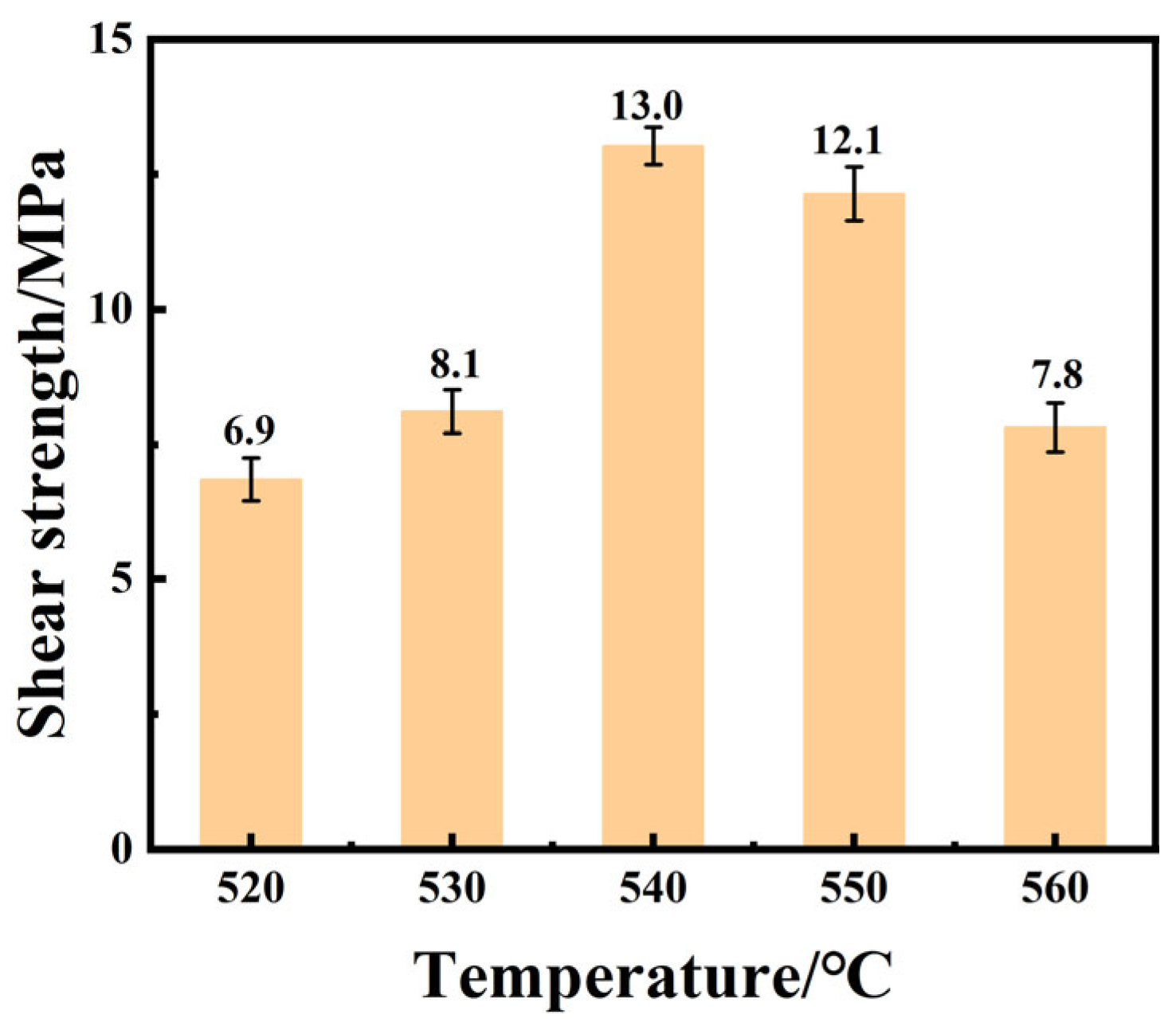
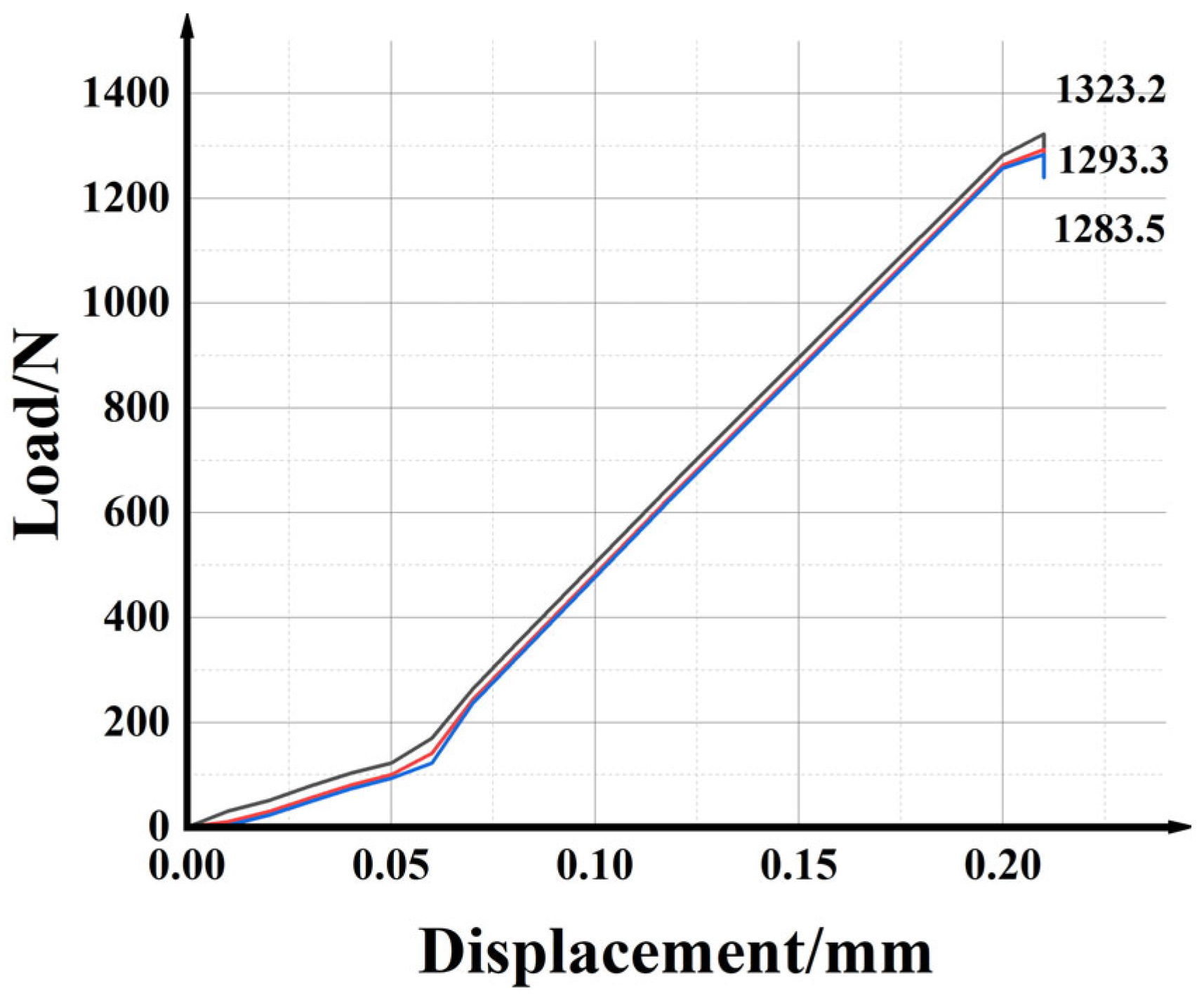
3.3. Shear Strength Analysis of the Joint

In order to find the best sealing temperature, the effect of the sealing temperature on the mechanical properties of the joint was studied. Three samples were tested for each sealing temperature. Figure 7 shows the shear strength of the joint at different sealing temperatures. It can be seen that the shear strength of the joint increased first and then decreased with the increase in the sealing temperature. When the sealing temperature was 520 °C, the shear strength of the joint was only 6.9 MPa, and the maximum shear strength of the joint was 13.0 MPa at 540 °C. However, the sealing temperature further increased to 550 °C and 560 °C, and the shear strength decreased to 12.1 MPa and 7.8 MPa, respectively. At low temperatures, the viscosity of glass filler was high, and the diffusion reaction between the glass filler and the base metal was weak. Additionally, cracking appeared after welding; therefore, the joint strength was low. With the increase in temperature, the element diffusion in the joint was excessive and some elements in the glass filler volatilized. These factors lead to the presence of large-diameter bubbles in the weld and the loose silicon–oxygen structure on the DM305 side, which had a significant negative impact on the shear strength.
Figure 8 shows the strain–stress curves for the samples during the shear test. Three curves of different colors are the results of three repeated shear tests. And the strain–stress curves increased sharply, reached their maximum peak, then decreased sharply. In the curve, no platform stage was observed, indicating the brittle fracture nature of the composite joint samples. The room temperature shear strength of the three brazed samples were 1323, 1293, and 1284 N, giving an average value of 1300 N at room temperature. Additionally, according to Equation (5), the shear strength was 13 MPa. The impact of the shear strength on the electronic packaging materials is less than that of air tightness, and the shear strength is generally between 3 and 15 MPa [17].
τ = F S
where τ is the shear strength of the joint (MPa), F is the maximum load applied (N), and S is the joint connection area (mm2).

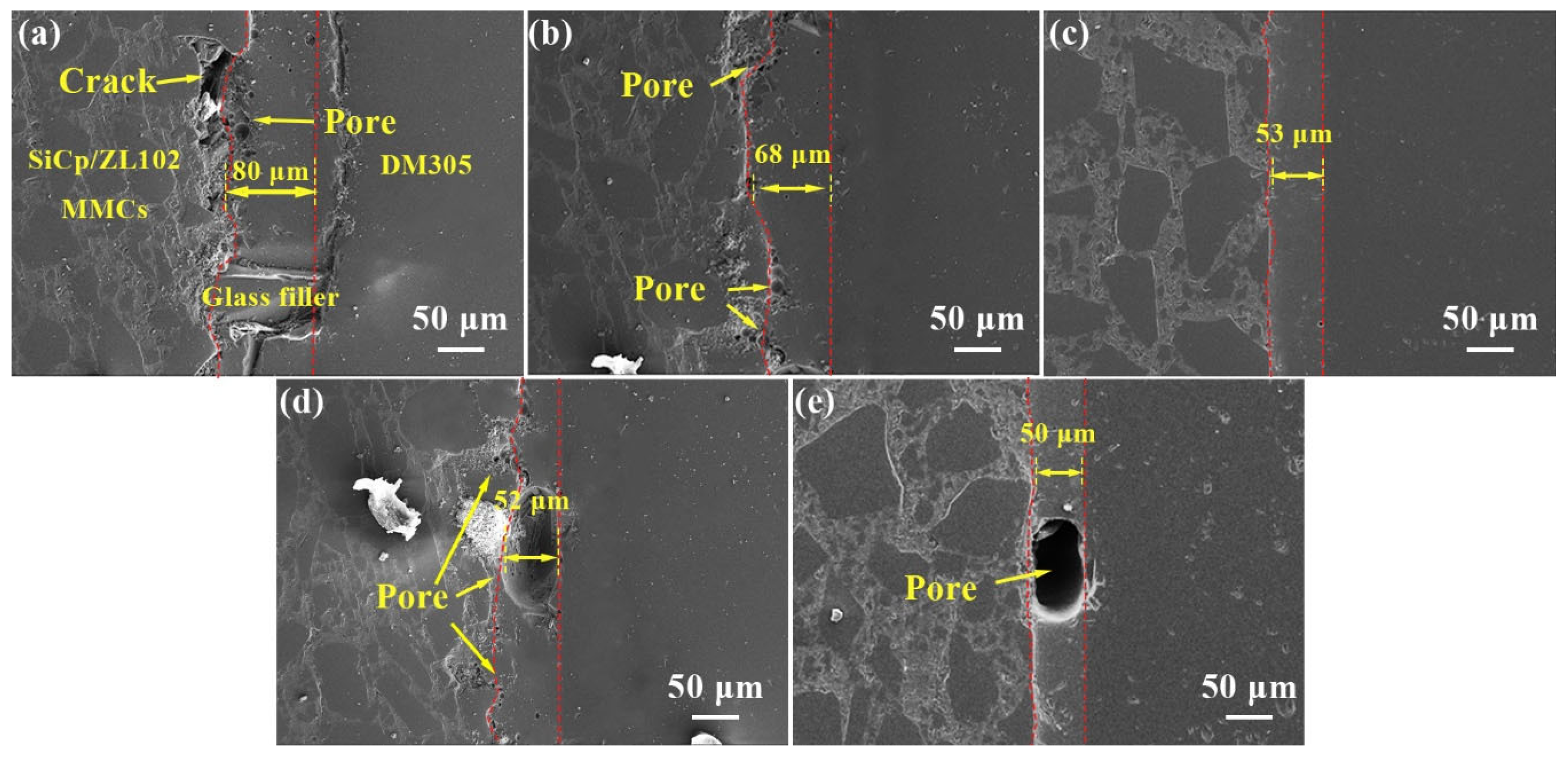
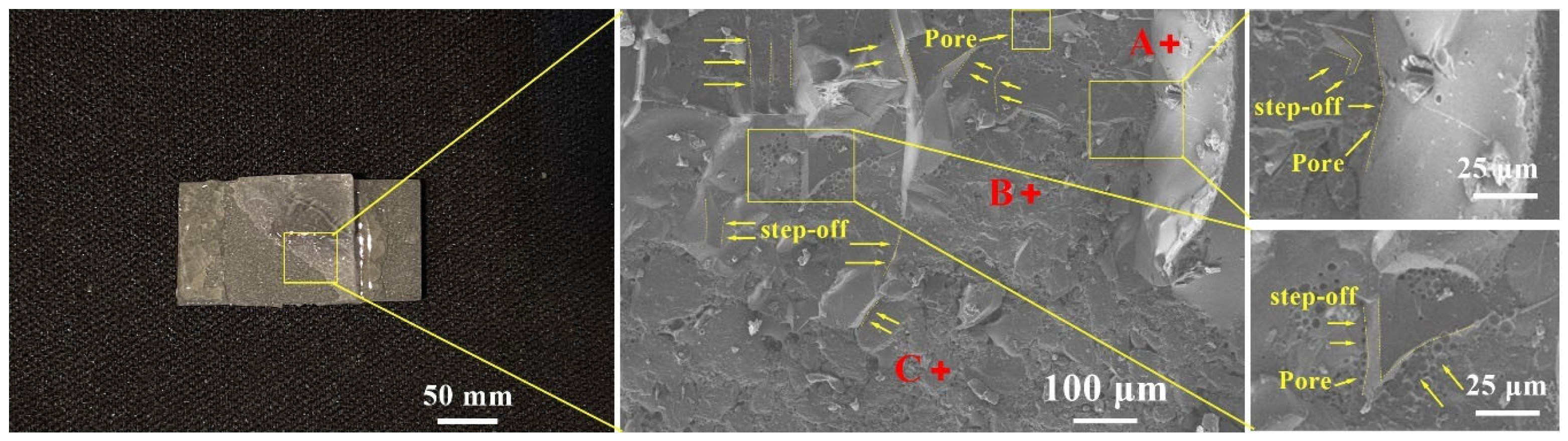
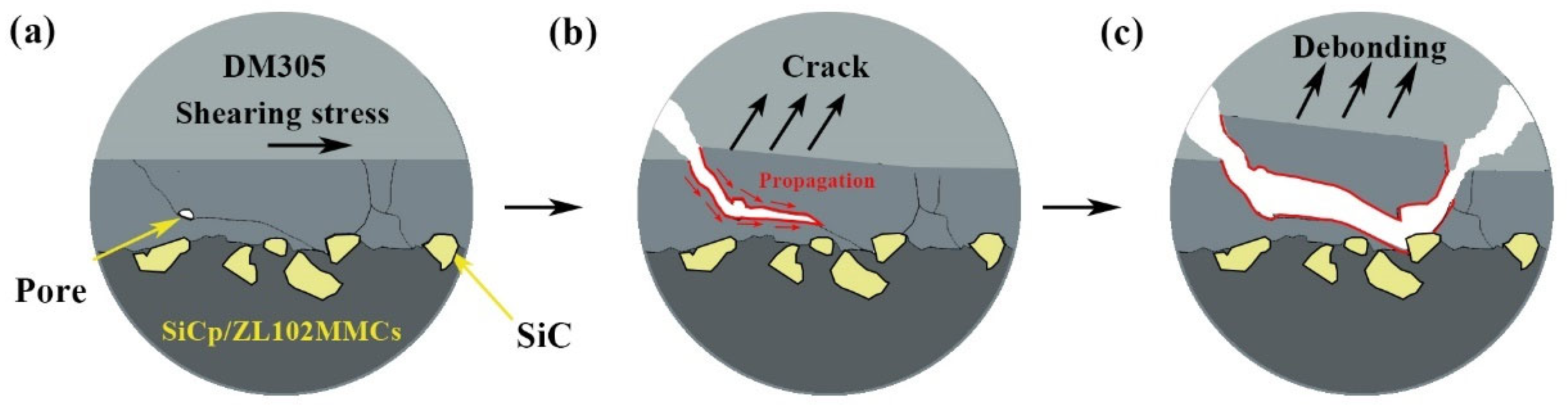
3.4. Fracture Analysis of the Sealing Joint

Figure 9 shows the shear fracture morphology of the sealed joint at 540 °C for 30 min. From a macro point of view, the DM305 glass broke in the middle, and half of the DM305 glass fell off. In addition, there was almost no glass filler on the surface of the composite on the falling side. According to the EDS element analysis in Table 4, point A is the DM305 glass, and point B is the glass filler, while point C is the SiC particles. It can be seen from Figure 9 that there were isolated pores on the fracture surface, and the fracture showed a step-like fracture morphology, a typical brittle fracture feature. From the local fracture magnification map, it can be seen that there were incomplete pores with a semi-circular arc at the root of the fracture step. This means that the fracture may occur at the pores in the weld and extend to the base metal on both sides.
The fracture micro-evolution process diagram of the joint is shown in Figure 10. The process of joint fracture was mainly divided into three stages: (a) the initiation of microcracks, (b) the propagation of cracks, and (c) the fracture of joints. During the heating and cooling process of the sealing test, there was residual stress in the sealing joint due to the different coefficients of thermal expansion between the three base metals. Under the action of shear stress parallel to the weld, the glass filler was subjected to tensile stress in the opposite direction of the base metal on both sides, resulting in micro cracks. As the shear stress further increased, the microcracks gradually expanded to the pores in the glass filler, causing the pores to rupture. The area of crack propagation gradually increased, and the crack extended to the sharp SiC particles exposed on the surface of the 65 vol% SiCp/ZL102 composites. Due to the stress-concentration effect, the joint ultimately suffered a fracture.

3.5. Air Tightness Tests of the Sealing Joints

The air tightness of a sealing joint is a crucial factor to evaluate the serviceability of electronic packaging products. The air tightness test can be used to detect whether there is a leakage problem at the sealing interface, and it can also verify the shear test results of the sealing joint more accurately. The air tightness detection of the sealing joints was strictly carried out in accordance with the Chinese national standard (GB/T 5594.1-1985), which requires that the leakage rate of helium from the sealed joint is less than or equal to 1.0 × 10⁻⁸ Pa·m3/s.
Table 5 lists the test results of the joint air tightness at different sealing temperatures for 30 min. When the sealing temperature was 530 and 540 °C, the air tightness test results were 1 × 10⁻⁸ Pa·m3·s−1 and 1 × 10⁻⁹ Pa·m3·s−1, respectively, which met the requirements of the Chinese national standards. At other sealing temperatures, there was gas leakage in the sealing joint. According to the microstructure of the joint obtained at different sealing temperatures, it was considered that the unwelded defects in the joint and the penetrating large pores were the main causes of the gas leakage phenomenon.

4. Conclusions

In this work, a 65 vol.% SiCp/ZL102 composite and DM305 electronic glass were successfully sealed by borosilicate glass in an atmospheric environment. The microstructures, shear testing, sealing mechanisms, and fracture mechanisms of the joints were analyzed to confirm the performance of the sealing joints. They provided a technical reference and theoretical values for the connection of high-volume fraction SiC/Al composites in an atmospheric environment. The main conclusions are summarized as follows:
(1)
The 65 vol.% SiCp/ZL102 composites and DM305 electronic glass can be sealed using the SiO2-B2O3-ZnO-NaO2 glass filler in air. The joint was well formed without defects, such as cracks and pores.
(2)
The shear strength of the joint initially increases and then gradually decreases as the sealing temperature rises from 520 to 560 °C. At a sealing temperature of 540 °C, the maximum shear strength of the joint can reach 13.0 MPa. The joint broke at the pores in the weld and ended on the surface of the 65 vol.%SiCp/ZL102 MMCs. Additionally, the leakage rate of air tightness was 1 × 10⁻⁹ Pa·m3/s.
(3)
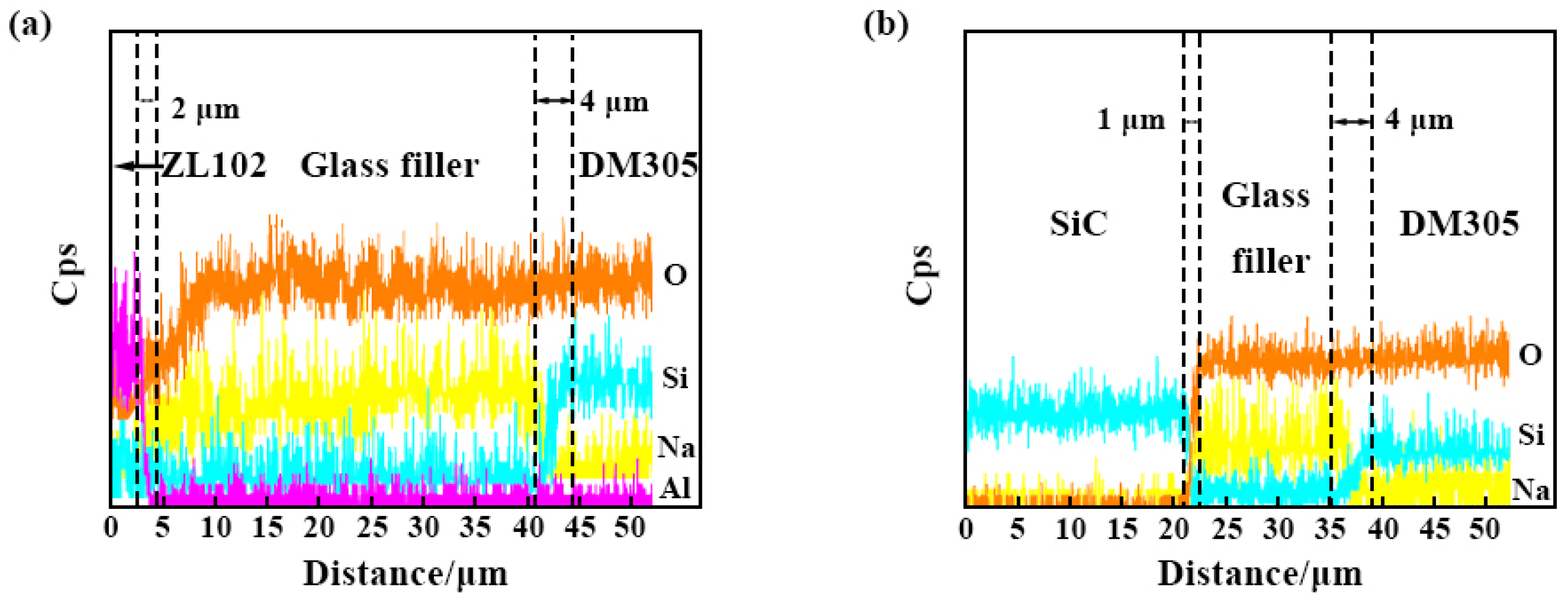
There are three different bonding interfaces in the joint: the DM305–glass filler, ZL102–glass filler, and SiC–glass filler. At the bonding interface of the DM305 glass–glass filler, Na and Si have a diffusive behavior, with a distance of about 4 μm. Na undergoes depolymerization, and the complex structure of the silicon–oxygen tetrahedron is depolymerized into a simple structure. At the ZL102–glass filler interface, Al and O have a diffusive behavior, with a distance of 2 μm, forming an effective connection. The bonding interface of the SiC–glass filler is serrated, and there is a diffusion layer of Si and O of about 1 μm.

Author Contributions

Investigation, D.Z., D.C. and X.H.; resources, J.N. and D.Q.; supervision, J.N.; writing—original draft preparation, D.Z.; writing—review and editing, D.C. and J.N. All authors have read and agreed to the published version of the manuscript.

Funding

The research was financially supported by the National Natural Science Foundation of China (No. 51245008), the Science and Technology Project of Henan Province, China (No. 222102220006), and the Key Project of Science and Technology Research of Henan Provincial Department of Education (No. 22B430016).

Conflicts of Interest

The authors declare no conflict of interest.

References

  1. Li, S.; Hu, K.; Hui, W.; Cai, Y.; Zhang, Y. Shear strength and interfacial characterization of borosilicate glass-to-metal seals. J. Alloys Compd. 2020, 827, 154275. [Google Scholar] [CrossRef]
  2. Ahn, B. Recent Advances in Brazing Fillers for Joining of Dissimilar Materials. Metals 2021, 11, 1037. [Google Scholar] [CrossRef]
  3. Yi, R.; Chen, C.; Li, Y.; Peng, H.; Zhang, H.; Ren, X. The bonding between glass and metal. Int. J. Adv. Manuf. Technol. 2020, 111, 963–983. [Google Scholar] [CrossRef]
  4. Shi, C.; Yi, R.; Chen, C.; Peng, H.; Ran, X.; Zhao, S. Forming mechanism of the repairing process on clinched joint. J. Manuf. Process. 2020, 50, 329–335. [Google Scholar] [CrossRef]
  5. Ferraris, M.; De la Pierre, S.; Sabato, A.G.; Smeacetto, F.; Javed, H.; Walter, C.; Malzbender, J. Torsional shear strength behavior of advanced glass-ceramic sealants for SOFC/SOEC applications. J. Eur. Ceram. Soc. 2020, 40, 4067–4075. [Google Scholar] [CrossRef]
  6. Ardestani, S.S.K.; Dashtizad, V.; Kaflou, A. Effects of temperature, time, atmosphere and sealing geometry on defects occurred in borosilicate glass-kovar alloy seal. Ceram. Int. 2021, 47, 2008–2015. [Google Scholar] [CrossRef]
  7. Khachatryan, H.; Lee, S.N.; Kim, Y.H.; Kim, K.B.; Kim, M. Temporary bonding of a thin metal foil to a glass substrate using glass powder for fabricating optical sensors. J. Korean Phys. Soc. 2021, 79, 19–24. [Google Scholar] [CrossRef]
  8. Khachatryan, H.; Baek, S.-H.; Lee, S.-N.; Kim, H.-K.; Kim, M.; Kim, K.-B. Metal to glass sealing using glass powder: Ion induced crystallization of glass. Mater. Chem. Phys. 2019, 226, 331–337. [Google Scholar] [CrossRef]
  9. Nazari, R.; Khoramishad, H. A novel combined anodic-adhesive bonding technique for joining glass to metal for micro device applications. Int. J. Adhes. Adhes. 2022, 117, 103175. [Google Scholar] [CrossRef]
  10. Zhang, M.; Chan, Y.; Chen, C.; Qiu, Z. A new sealing technology for ultra-thin glass to aluminum alloy by laser transmission welding method. Int. J. Adv. Manuf. Technol. 2021, 115, 2017–2035. [Google Scholar] [CrossRef]
  11. Yanik, M.C.O.; Demirel, O.; Elmadagli, M.; Gunay, E.; Aydin, S. Investigation of glass sintering to improve strength and interfacial interactions in glass-to-AISI 316L metal joints. Int. J. Appl. Glass Sci. 2023, 14, 256–267. [Google Scholar] [CrossRef]
  12. Chen, Z.; Ikeuchi, K.; Takahashi, M.; Nishikawa, S. Electric Field-assisted Anodic Bonding of Glass to Kovar Alloy. Trans. China Weld. Inst. 2001, 22, 21–25+3. [Google Scholar]
  13. Feng, G.J.; Li, Z.R.; Xu, X.L.; Shen, Z.K.; Yang, Y. Glass-Copper anodic bonding through activated Sn-0.6Al solder. J. Mater. Process. Technol. 2018, 254, 108–113. [Google Scholar] [CrossRef]
  14. Utsumi, A.; Ooie, T.; Yano, T.; Katsumura, M. Direct Bonding of Glass and Metal Using Short Pulsed Laser. J. Laser Micro Nanoeng. 2007, 2, 133–136. [Google Scholar] [CrossRef]
  15. Ji, C.-H.; Huang, Y.-J.; Chen, X.; Jiang, J.-Y.; Guo, Z.-J.; Long, Y. Direct microwelding of dissimilar glass and Kovar alloy without optical contact using femtosecond laser pulses. J. Cent. South Univ. 2022, 29, 3422–3435. [Google Scholar] [CrossRef]
  16. Xu, L.; Chen, Z.; Li, C.; Wang, Y.; Mi, G. Sealing mechanism of interface between 55%SiCp/6061 Al composite materials and PbO-ZnO-B2O3 glass. Rare Met. Mater. Eng. 2018, 47, 169–174. [Google Scholar]
  17. Chu, J.; Gao, Z.; Wang, Z.; Niu, J.; Tao, X. Process and Properties of Brazing of High Volume SiCp/6063Al Composites and Electronic Glass with Low Temperature Glass Solder. Mater. Rep. 2021, 35, 24062–24067. [Google Scholar] [CrossRef]
  18. Wang, Z.; Gao, Z.; Chu, J.; Qiu, D.; Niu, J. Low Temperature Sealing Process and Properties of Kovar Alloy to DM305 Electronic Glass. Metals 2020, 10, 941. [Google Scholar] [CrossRef]
  19. Ferraris, M.; Gili, F.; Lizarralde, X.; Igartua, A.; Mendoza, G.; Blugan, G.; Gorjan, L.; Casalegno, V. SiC particle reinforced Al matrix composites brazed on aluminum body for lightweight wear resistant brakes. Ceram. Int. 2022, 48, 10941–10951. [Google Scholar] [CrossRef]
  20. Samal, P.; Vundavilli, P.R.; Meher, A.; Mahapatra, M.M. Recent progress in aluminum metal matrix composites: A review on processing, mechanical and wear properties. J. Manuf. Process. 2020, 59, 131–152. [Google Scholar] [CrossRef]
  21. Guo, W.; Hou, J.; Lin, T.; He, P. Joining high volume fraction SiC particle reinforced aluminum matrix composites (SiCp/Al) by low melting point stannous oxide–zinc oxide–phosphorus pentoxide glass. Ceram. Int. 2021, 47, 3955–3963. [Google Scholar] [CrossRef]
  22. Wang, F.; Zhou, J.; Wu, S.Y.; Kang, X.M.; Zhao, W.S. Study on material removal mechanism of photocatalytic-assisted electrochemical milling-grinding SiCp/Al. Int. J. Adv. Manuf. Technol. 2023, 124, 817–832. [Google Scholar] [CrossRef]
  23. Zoubenko, E.; Iacopetti, S.; Weinfeld, K.; Kauffmann, Y.; Van Cleemput, P.; Eizenberg, M. Impact of chemical bonding difference of ALD Mo on SiO2 and Al2O3 on the effective work function of the two gate stacks. J. Vac. Sci. Technol. A 2021, 39, 043201. [Google Scholar] [CrossRef]
  24. Dong, R.-K.; Mei, Z.; Xu, S.-Y.; Zhao, F.-Q.; Ju, X.-H.; Ye, C.-C. Molecular dynamics simulation on reaction and kinetics isotope effect of nano-aluminum and water. Int. J. Hydrogen Energy 2019, 44, 19474–19483. [Google Scholar] [CrossRef]
  25. Yang, C.; Bai, J.; Wang, G.; Wang, H.; Ma, S. Effect of Na2O content on wettability, crystallization and performances of sealing glass. J. Mater. Res. Technol. 2023, 23, 4117–4134. [Google Scholar] [CrossRef]
  26. Barlet, M.; Delaye, J.-M.; Boizot, B.; Bonamy, D.; Caraballo, R.; Peuget, S.; Rountree, C.L. From network depolymerization to stress corrosion cracking in sodium-borosilicate glasses: Effect of the chemical composition. J. Non-Cryst. Solids 2016, 450, 174–184. [Google Scholar] [CrossRef]
Figure 1. Microstructure of 65vol.% SiCp/ZL102 MMCs.
Metals 13 00817 g001
Figure 2. Assembly schematic diagram.
Metals 13 00817 g002
Figure 3. Process curves of sealing with different sealing temperatures.
Metals 13 00817 g003
Figure 4. SEM images of the typical sealing joints at different sealing temperatures for 30 min: (a) 530, (b) 530, (c) 540, (d) 550, and (e) 560 °C.
Metals 13 00817 g004
Figure 5. SEM images of the typical sealing joints at 540 °C for 30 min: (a) Overall morphology, (b) partially enlarged detail.
Metals 13 00817 g005
Figure 6. The line scanning results in Figure 5: (a) ZL102–Glass filler–DM305, (b) SiC–Glass filler–DM305.
Metals 13 00817 g006
Figure 7. Shear strength of joints at different sealing temperatures.
Metals 13 00817 g007
Figure 8. Strain–stress curves for the joint during shear tests.
Metals 13 00817 g008
Figure 9. The fracture morphology of the joint at 540 °C for 30 min.
Metals 13 00817 g009
Figure 10. Fracture process evolution diagram of joint: (a) the initiation of microcracks, (b) crack propagation, (c) fracture of the joint.
Metals 13 00817 g010
Table 1. Chemical composition of ZL102 (in wt.%).
ElementSiFeCuMnMgZnTiAl
Wt.%10.0–13.00.0–0.7≤0.30≤0.50≤0.10≤0.10≤0.20Balance
Table 2. Chemical composition of DM305 electronic glass (in wt.%).
CompositionSiO2Al2O3B2O3K2ONa2O
Content67.5 ± 1.03.5 ± 0.520. 3 1.0 + 0.5 4.9 ± 0.33.8 ± 0.3
Table 3. Coefficient of thermal expansion of 65 vol.% SiCp/ZL102 MMCs, DM305 electronic glass, and glass filler (0~300 °C).
Material65 vol.% SiCp/ZL102DM305 Electronic GlassGlass filler
CET × 10−7/°C8.04.96.5
Table 4. EDS analysis results of each point in Figure 9 (in wt.%).
PointOSiNaAlCZnPhase
A56.634.16.33.0--DM305
B56.920.415.54.2-3.0Glass filler
C0.449.2--50.4-SiC
Table 5. Air tightness of the sealed joints at different sealing temperatures.
Temperature/°C520530540550560
Leak rate/Pa·m3·s−1---1 × 10−81 × 10−9------
Disclaimer/Publisher’s Note: The statements, opinions and data contained in all publications are solely those of the individual author(s) and contributor(s) and not of MDPI and/or the editor(s). MDPI and/or the editor(s) disclaim responsibility for any injury to people or property resulting from any ideas, methods, instructions or products referred to in the content.

