
Hot Forging Die Design Optimization Using FEM Analysis for Near-Net Forming of 18CrNiMo7-6 Steel Pinion Shaft
by
 and
and
Nijenthan Rajendran
1,
Charles Chemale Yurgel
1,
Wojciech Z. Misiolek
1 and
Ricardo Alves de Sousa
2,*
1
Loewy Institute, Materials Science and Engineering Department, Lehigh University, Bethlehem, PA 18015, USA
2
Center for Mechanical Technology and Automation, Department of Mechanical Engineering, Campus de Santiago, University of Aveiro, 3810-183 Aveiro, Portugal
*
Author to whom correspondence should be addressed.
Metals 2023, 13(4), 815; https://doi.org/10.3390/met13040815
Submission received: 1 March 2023
/
Revised: 1 April 2023
/
Accepted: 17 April 2023
/
Published: 21 April 2023
(This article belongs to the Topic Numerical and Experimental Advances in Innovative Manufacturing Processes)
Abstract
:The objective of the presented work was to develop a new forging process for a pinion shaft as a component of a wind turbine. A study of near-net-shape forming using Deform 3D software was performed to reduce operational cost, time, and material scrap; enhance specific properties; increase productivity. Near-net forged products have good dimensional accuracy and continuous metal flow lines, which are characteristic of improved mechanical properties. To avoid the traditional trial-and-error experimental method, the process and tool design were accomplished with a careful and detailed numerical simulation approach. In the present work, the Finite Element Method was used to develop a process model for the existing hot forging process of the 18CrNiMo7-6 steel pinion shaft used in a wind turbine. The developed numerical process model was validated via experiment including a comparison of the metal flow lines from the FEM model with the metallography results of the forged part. Two new die designs were proposed, and the simulation results were compared to the actual process to achieve improved geometry. The results for the new geometries showed improvements in terms of the die cavity filling for the new proposed dies and better results in grain flow orientation. Compared to the initial non-optimized die, the new designs improved the mechanical properties and savings associated with the lower volume of required raw material and fewer finishing operations. Considering the applied stresses and wear in the new near-net shape, the die geometry shall be updated to accommodate more severe solicitations. Naturally, all the improvements carried out are dependent on other factors such as the conditions of the equipment, operator skills, lubrication, and other variables. A surface heat treatment is also suggested for stress relief as a reliability improvement.
1. Introduction
Hot forging is a metal forming process whose main objectives are not only to change the shape but also improve the mechanical properties of the forged parts measured by ultimate tensile strength and ductility. Hot forging is defined as the process in which metal is plastically deformed above the recrystallization temperature [1,2]. The metal workpiece is heated up to the desired temperature and deformed with the impact energy of tooling in the closed-die hot forging process. In this process, the service life of the forging dies is especially important due to economic reasons and, also, to the quality of forged components. The flash formation during forging requires high levels of effective stress because of highly localized yield stress and high active friction surfaces. The small thickness of the flash due to the high surface-to-volume ratio is much cooler than the bulk of forging, resulting in a higher material yield stress value [2,3].
In the hot forging processes, the final-part geometry impacts process parameters due to complex interactions between tooling and ingots, which can result in inhomogeneous temperature and stress distributions within the part. The forging process is usually carried out under extreme thermal conditions to reduce the ingot’s yield stress and increase its formability. As a result of these complex interactions, high mechanical loads occur during forming, influencing the final process [4]. The results change with the selection of the manufacturing process of complex-part geometry such as gears, shafts, and forged components with teeth. The traditional gears are mass-produced by the machining process with a high production time and high scrap rate, which additionally requires specialized machining tools. To avoid that and, at the same time, search for improved product mechanical properties, the forging process can be widely regarded as a green manufacturing technology to improve mechanical properties in comparison with machining and casting processes. This is especially true for complex shapes with the presence of a continuous metal flow, resulting in deformed inclusions and improved mechanical properties [5,6].
While designing and manufacturing forged parts with complex geometry such as pinion shafts and bevel gears, with specific mechanical properties, it is important to evaluate the required material volume and eventual post-processing heat-treatment operations. In the case of designing a forging process at different temperatures, the forged part shows various physical characteristics at each part location because the microstructure, temperature, and strain are not the same [7,8]. Hence, to obtain the required mechanical properties in the mentioned complex parts, a proper material grade needs to be selected based on the standard mechanical properties together with the state of stress applied during forging [2,9].
Structural forging steels often require surface hardening, which is achieved through carburizing and other hardening operations to achieve high surface hardness with a good toughness of the part’s core. The forged components used in the wind turbine, such as pinion shafts, are used in the case-hardened stage to replace the parts of the same geometry typically manufactured by the machining operation. Due to the increased mechanical properties of the forged parts, their dimensions and mass can be reduced [10,11]. A typical forging steel needs to be heat-treated and the surface-modified layer plays an important role in forged components to enhance the mechanical and/or chemical surface properties and improves the fatigue life. These types of components typically are exposed to large strains, which induce significant microstructure evolution and the development of the metal flow pattern throughout the part. Various locations of the forged part are submitted to a different deformation path and to grain fragmentation, to the stretching of ductile inclusions, and to the alignment of hard inclusions, resulting in heterogeneous grain flow patterns [12,13].
A pinion shaft part is a round rod with teeth located parallel to its length, and it is externally connected to a gear mechanism. Pinion shafts, made of 18CrNiMo7-6 steel material, are used for transmitting torque from the motor to the gearbox and are widely used in many industrial components, specifically in high-speed heavy-duty gear applications [13]. The formation of angular carbides during the carburizing process can also be influenced by the completed machining operation and result in cracks. The presence of cracks can significantly reduce the fatigue strength and service life of 18CrNiMo7-6 steel components. The hot forging process is presented as a viable process to improve fatigue life [13,14].
Therefore, this kind of steel component is often surface-treated to increase its service life, which depends mainly on the part’s surface condition. The surface of the dies needs to be treated depending on the hot forging process parameters (type of equipment, lubricant, temperature, speed, etc.) and the geometry of the forged part to balance the high tensile stresses applied to the dies [6,14,15].
The forging process optimization has been focused on minimizing material scrap in recent years [16]. Additional benefits of near-net-shape forming include a reduction in the energy required in the manufacturing process, resulting in reduced costs and a more environmentally sustainable production through reducing scrap and the carbon footprint. The near-net-shape forged components have good dimensional accuracy, continuous grain flow lines, and superior strength. However, the near-net-shape forging of complex shapes such as gears has certain drawbacks such as a high forging load needed to fill up the die cavity corners of the gear teeth, the intricate die design required, and a higher tonnage capacity of the press being needed in comparison to simple geometries [16,17].
The FEM is a well-known tool technique used to numerically evaluate strains and stresses in dies and forged parts, avoiding trial-and-error and sparing time and cost production. The optimization steps based on validated numerical results are relevant to evaluate steps and blows, to verify the die service life and forged parts in service. Different materials can be virtually tested as well as process parameters such as loads and speeds [18,19].
The DEFORM-3D® software is a process simulation platform designed to analyze the three-dimensional (3D) metal flow in complex metal forming processes. It can model the deformation of complex shapes to replace the expensive and time-consuming trial-and-error in manufacturing processes and is an efficient tool to predict the material flow in industrial forming operations without the additional cost and delay on the plant floor. The simulation platform can predict high and low material strains and thermal behavior with high precision [20,21,22].
Banded ferrite-perlite structures, in general, are heterogeneous structures that react non-uniformly during hot forging. Such structures affect the final residual stress and can generate distortions in the forged material. To reduce the effects of banded structures of ferrite-perlite, coming from the segregation of elements such as carbon and chromium, homogenization heat treatments are applied by cooling in air. However, it is necessary to perform a normalization heat treatment afterward to reduce the grain sizes resulting from the origin of the material and the effects of chemical composition in forging. This is performed to reduce the possibility of distortions because of the presence of the residual stress in gear teeth manufactured by machining [23,24,25].
The objective of this work was to utilize the FEM package DEFORM-3D for optimization of the preform geometry and prediction of the metal flow in forged workpieces including the strain distribution and microstructure gradients. The hammer process was applied to 18CrNiMo7-6 steel in a numerical simulation and on the plant floor and the modeling results were compared to the collected industrial data. The CAD models of the preforms and forging dies were prepared and imported into DEFORM–3D to analyze the effect of preform geometry on forging loads and effective stress for the fully filled die cavity. The macro flow lines were compared to the results of the FEM simulations and allowed analysis of the two proposed preform geometries.
2. Materials and Methods
2.1. Experimental Work
The experimental part of the presented research started with evaluating the chemical composition of raw material, namely 18CrNiMo7-6 steel. The initial material was received from the partner company after ingot casting and hot rolling with a reduction of 18.2:1 with a diameter of 152.4 mm and length of 15 m. The chemical composition of the steel used in the experiments is presented in Table 1. Data was obtained using an optical emission spectrometer Thermo ARL Analyzer/Thermofisher Scientific, Waltham, MA, USA).
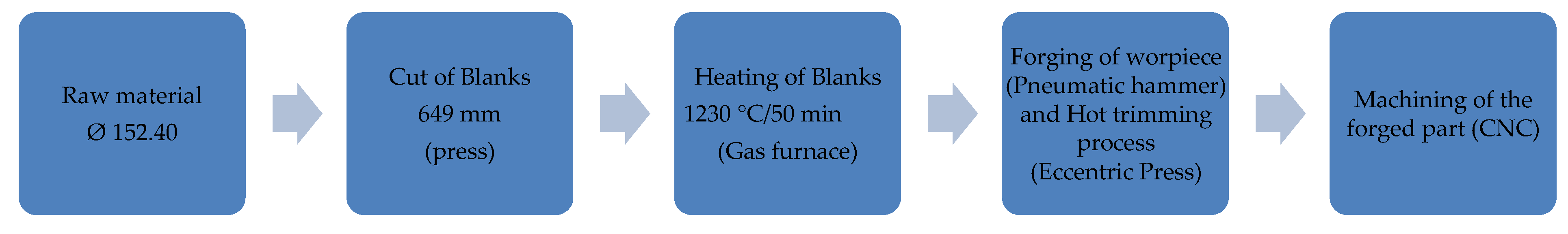
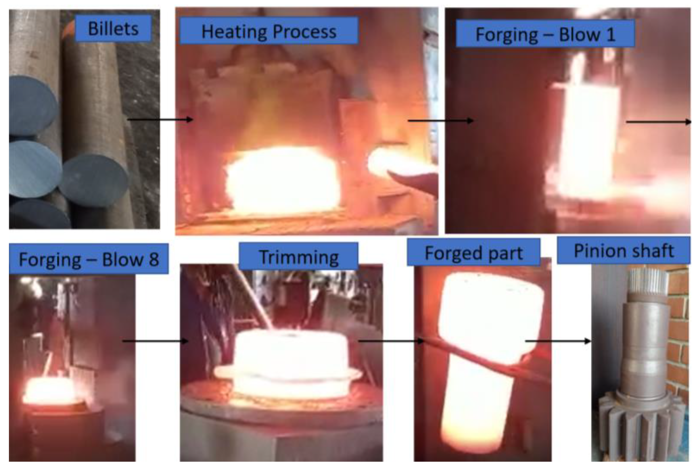
The first step in the forging process was to cut the billets into the dimension required by the actual forging process on a bandsaw with each billet measuring 649 mm in length and 152.4 mm in diameter. To obtain the proposed pinion shaft’s final geometry, a tooling set consisting of a lower and an upper die using 56NiCrMoV7 steel, appropriate for the hammering process, was designed. The material flow in the hot forging process was presented using the sequence of heating the billets in an FNSA chamber furnace with a 1500 kg/h capacity and natural gas heating at a temperature of 1230 °C for 50 min. After that, the heated billet was driven to the pneumatic Beche DG 12.5 drop hammer, and with seven or eight blows, the hot forging process was completed. To finish the high-temperature process, the last step was to remove the flash on the eccentric press (Mankel, Michigan, USA) with a capacity of 4500 kN. To evaluate the fiber orientation in the specimens, the manufacturing process followed the flowchart described below and detailed in Figure 1 with the configuration of the process and the main sequence of the analyzed manufacturing process presented by actual photographs in Figure 2.
The sequence of sectioning of the raw material as well as of the forged part, to enable the metallography analysis, was performed in the longitudinal and transversal directions, as shown in Figure 3, with the main objective to evaluate the grain flow orientation.
Sectioning was followed by the milling and grinding operations using sandpaper with the following grades: #120, #280, #320, #400, and #600. The metallography analysis of the flow lines before and after forging was performed using an etching reagent with 10 g of iodine plus 20 g of iodine with potassium and 200 mL of water for two minutes.
2.2. Numerical Model and Validation
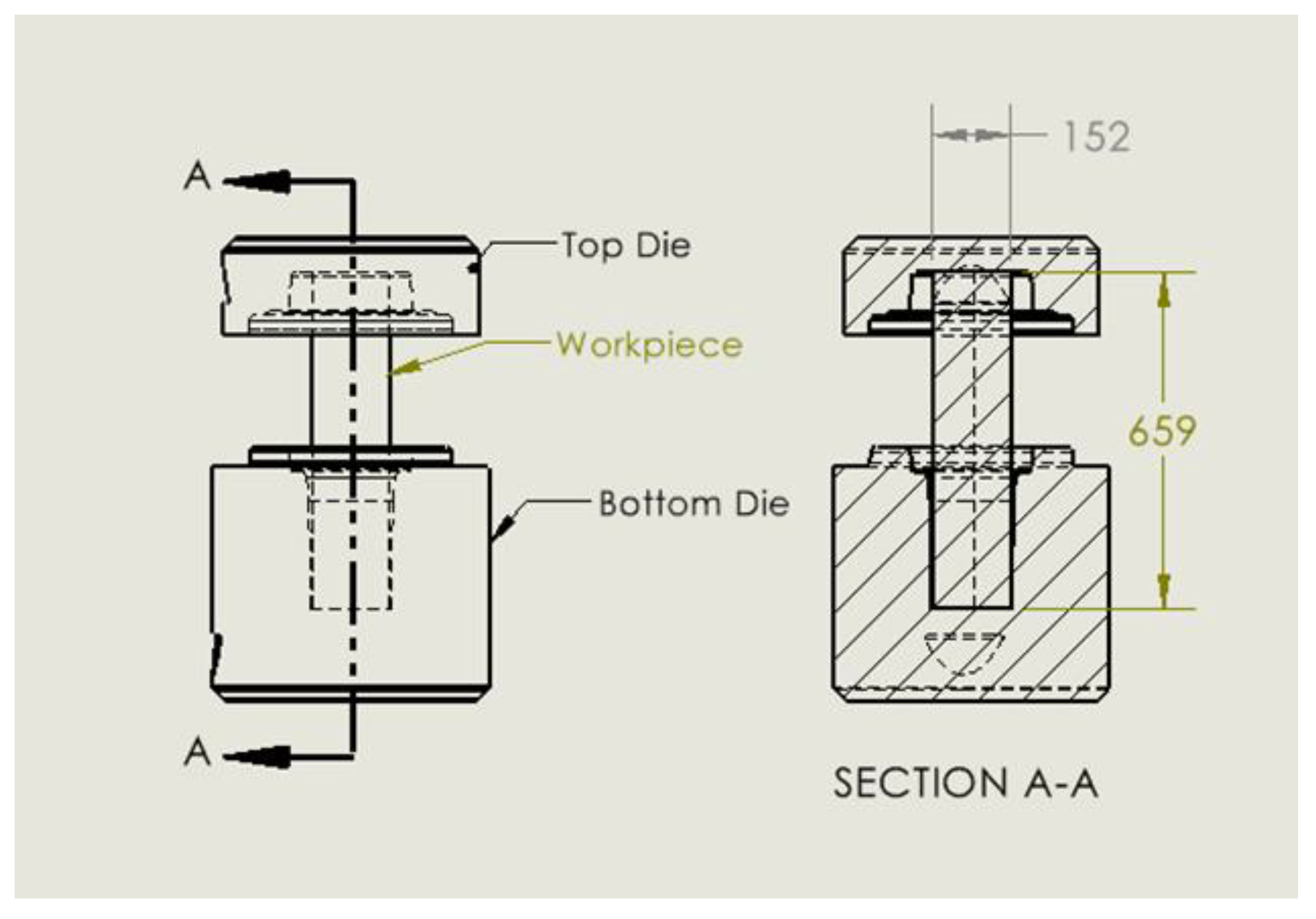
Numerical simulation process models for 18CrNiMo7-6 steel hot forging were developed using DEFORM 3D (Scientific Forming Technologies Corporation, Columbus, OH, USA). The assembly CAD file provided by the company, as shown in Figure 4, was imported to DEFORM 3D. The workpiece was modeled as plastic and the tooling as a rigid material. The flow stress data for 18CrNiMo7-6 consisted of data ranging from 900 °C to 1150 °C with 50 °C increments for three different strain rates of 0.1 s−1, 1 s−1, and 5 s−1 taken from the literature [23]. The tool material 56NiCrMoV7 steel with a hardness value of 60HRC was used as the die material. The tool’s initial temperature was kept at 300 °C and the workpiece’s initial temperature was kept at 1200 °C (close to data provided from the company and used in the actual forging process). For the die movement, a hammer type was chosen, with a total hammer energy of 1.2 × 10⁵ J. The mass of the primary top die was maintained at 16 tons and the counter hammer mass was maintained at 17 tons with a stiffness value of 1 × 10⁸ N/mm. As it is a multi-blow forging process, a blow table was created as shown in Table 2. The percentage of the total hammer energy used constantly increased from the initial first blow to the final blow as more energy is required to force a flash formation and to completely fill the die cavity. The efficiency was assumed to be 100%, using all the blow energy to deform the workpiece with no energy loss. After each blow, the top die went up and remained in that position for 1 s before coming down for the second blow.
The Archard wear model as shown in Equation (1) was used to predict the tool wear depth.
where zab is the abrasive wear depth, p is the interface pressure, v is the local sliding velocity, dt represents the incremental time step, H is the tool hardness, and K, a, b, and c are experimental constants. The shear friction factor of 0.3 and interface heat transfer coefficient of 11 N/s mm °C were used between the workpiece and tooling. The local pressure and velocity were calculated as the numerical simulation runs, and exponent values were taken as a = 1, b = 1, and c = 2 for steel tools, respectively. The coefficient K represents the magnitude of predicted tool wear and usually has a value of the order of 1 × 10⁻⁶ to 1 × 10⁻⁷.
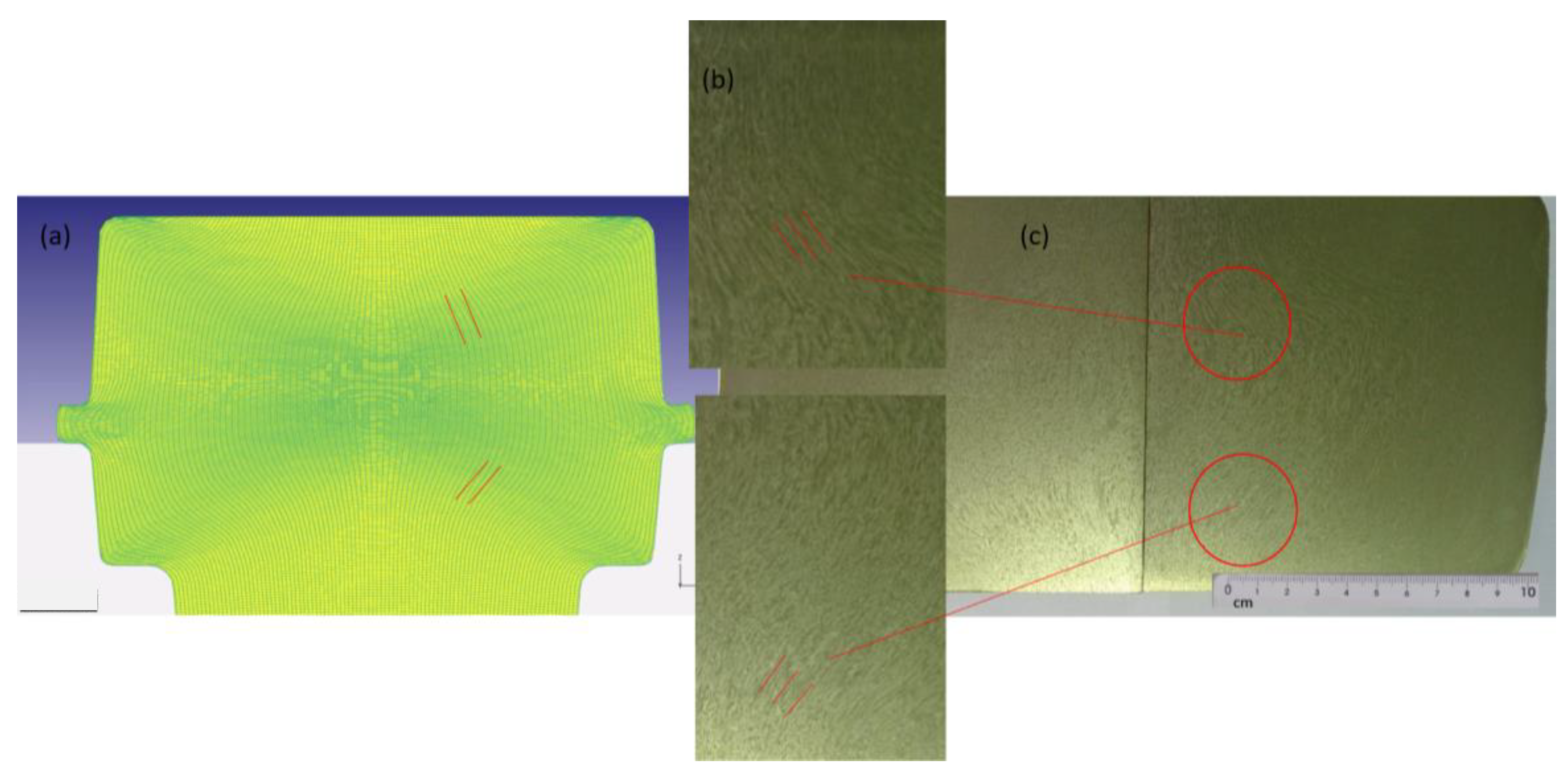
The numerical simulation process model for 18CrNiMo7-6 steel took eight blows to fill the die cavity, identical to that in the actual forging process with a maximum load of 4603 tons, as shown in Figure 5a and with the drawing of the forged part in Figure 5b. To validate the developed process model, results predicted from the simulation were compared to the actual forging process parameters provided by the company. First, the metal flow pattern observed in the deformed part using the metallography technique was compared with the flow pattern predicted by the process model as shown in Figure 6. As one can see in Figure 6a, the flow pattern (highlighted by the red lines) predicted from the process model did match the actual metal flow pattern in the forging process shown in the middle of the magnified portion of Figure 6b. Secondly, the tool conditions were checked and compared to the original tool in the forging process. Die stress analysis and a tool wear depth study were performed to analyze the tool behavior in the process model.
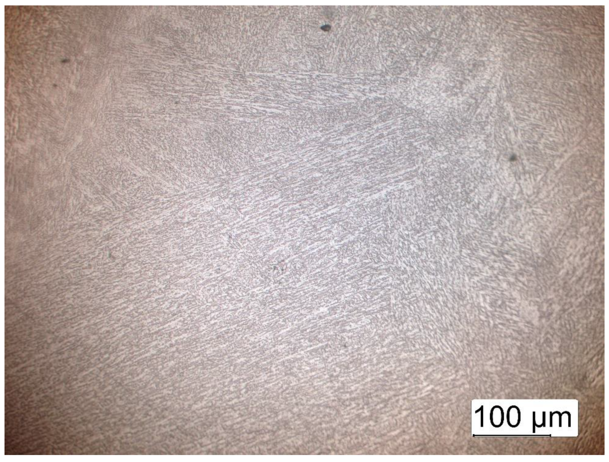
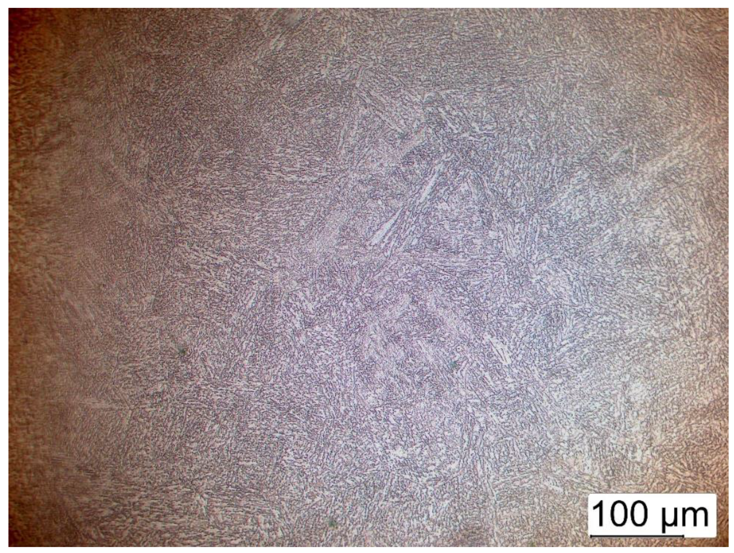
Considering the thermomechanical work of hot rolling on the ingot material (austenitic grain size of 7 ASTM, billet) and subsequent forging steps of the forging head, in Figure 7, the results were observed in the fiber direction area of the same point presented in the macrograph (of the bottom part of Figure 6), martensite phase, and also the boundaries of the former austenite grain size resulting from recrystallization, demonstrated in the micrographs. For the position closest to the flash area of Figure 8, similar microstructures were observed with grain formation with small differences, showing the need to apply normalization heat treatment for grain refinement.
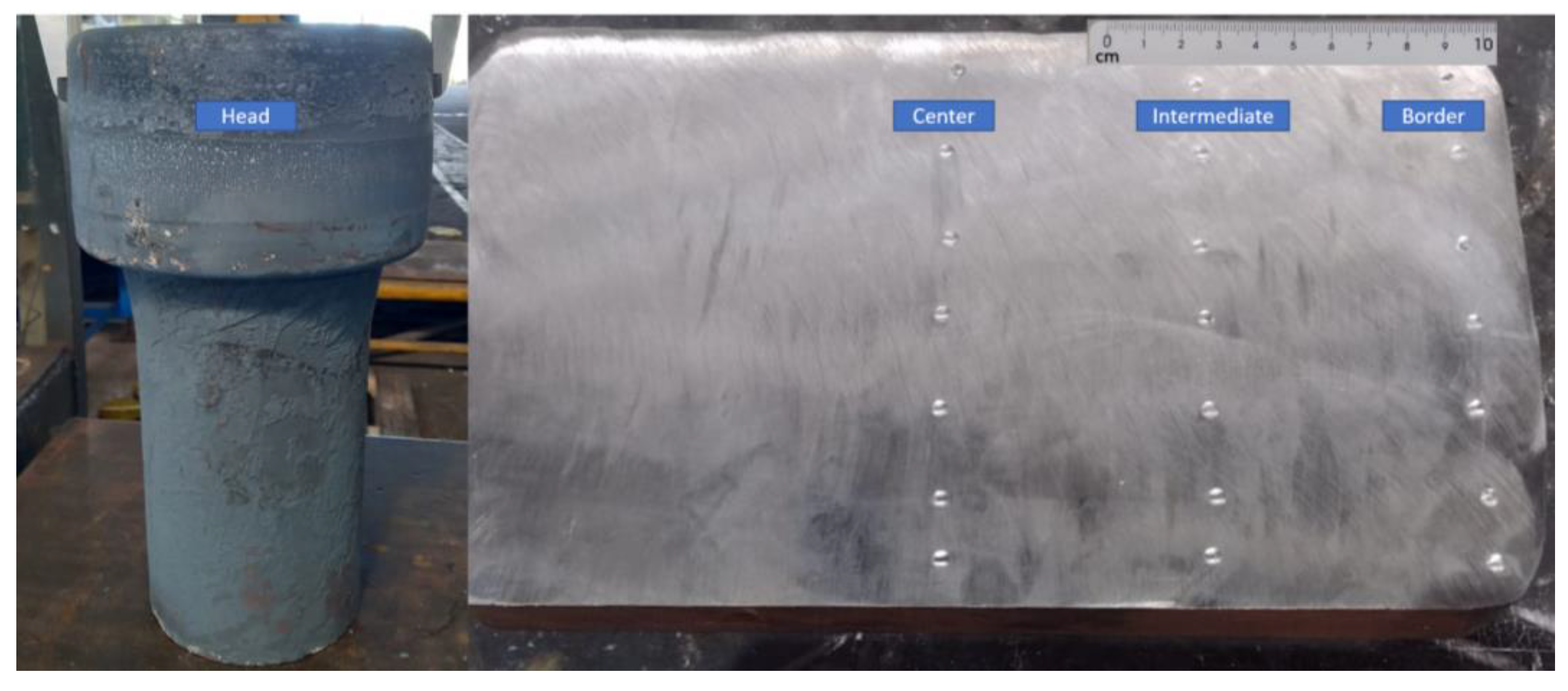
The Brinell hardness test was applied to the forging head, as shown in Figure 9, to verify the results of the forging process, considering the high reduction rate of the hot rolling and the steps of the hot forging processes. The tests were applied according to the standard ASTM A370 for forged parts. The mechanical properties were verified and specified to hardness measurement with a load of 3000 kg and indenter’s size of 10 mm. There were seven measurements made along the center, intermediate, and border vertical lines, as shown in Figure 9. The variation in the measurements in the forged head was between 302 HB and 311 HB, which shows how uniform the processed material was.
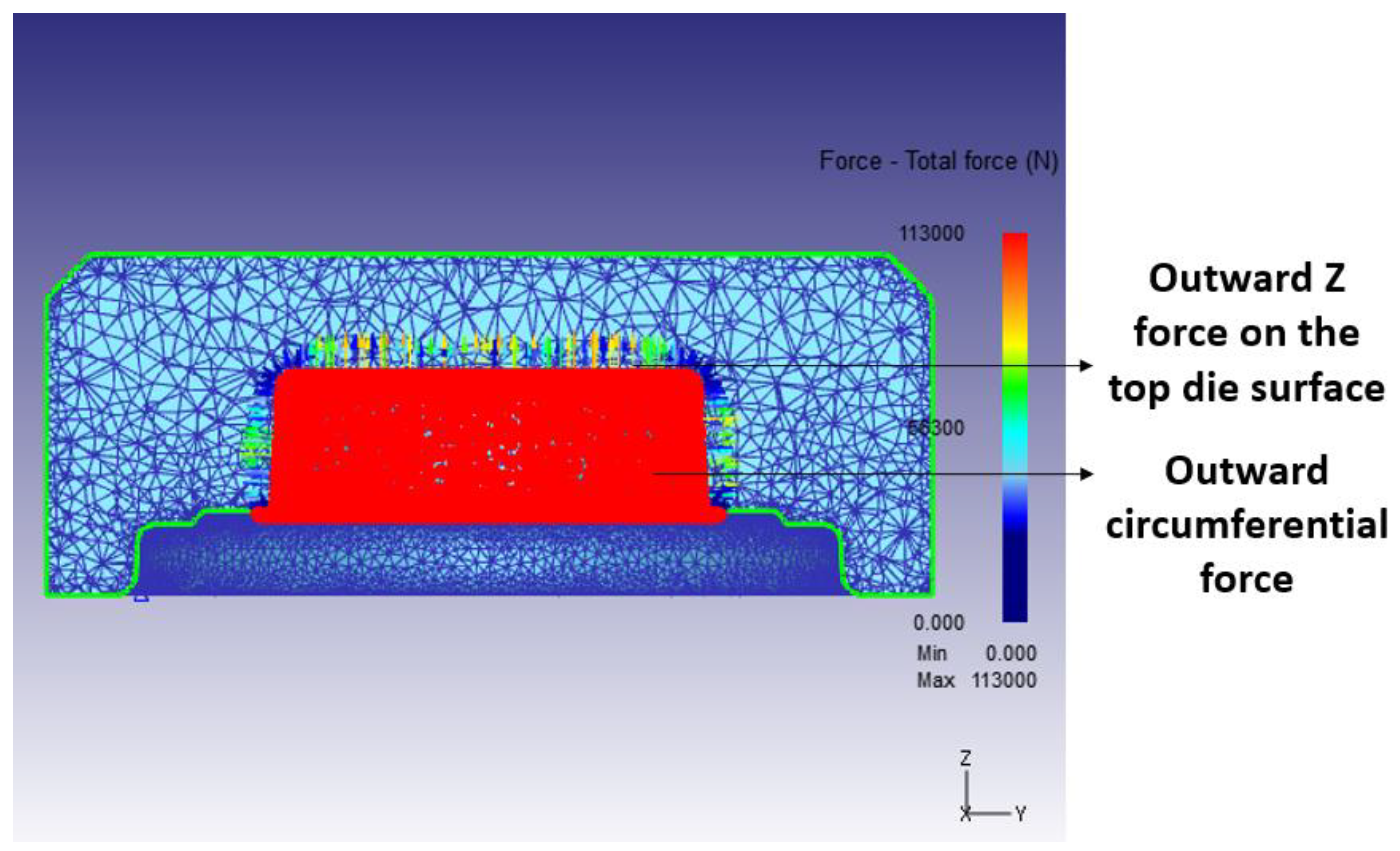
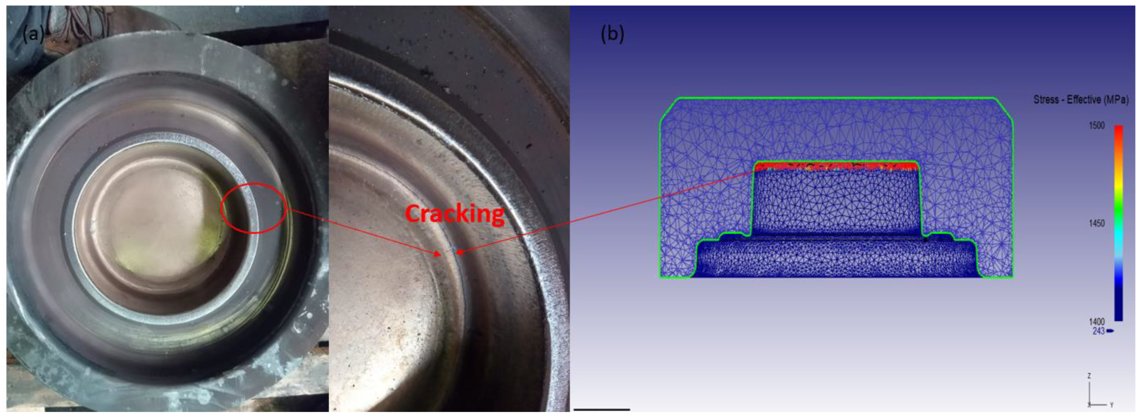
For the die stress analysis, a step in which the tool experiences the maximum load was taken for the final blow where the flash formed, as shown in Figure 5. The stress study for a new die was generated in DEFORM 3D® where the model considers the tools’ material with elastic properties at that step. The forces applied by the workpiece at that step on the tools were interpolated in the model, as shown in Figure 10. To study which region of the tool experiences maximum stress and to check what kind of stress that region is under, both effective stress and maximum principal stress distribution were investigated. Based on the effective and maximum principal stress distribution, it was possible to check that the outer circle in red color experienced maximum stress, which was in tension, as shown in Figure 11. This would indicate that the probability of cracking in that region is higher, which was the actual case, as seen in Figure 12a, indicating the critical points to pay attention to in order to extend the die life, and where to apply superficial treatments to improve mechanical resistance.
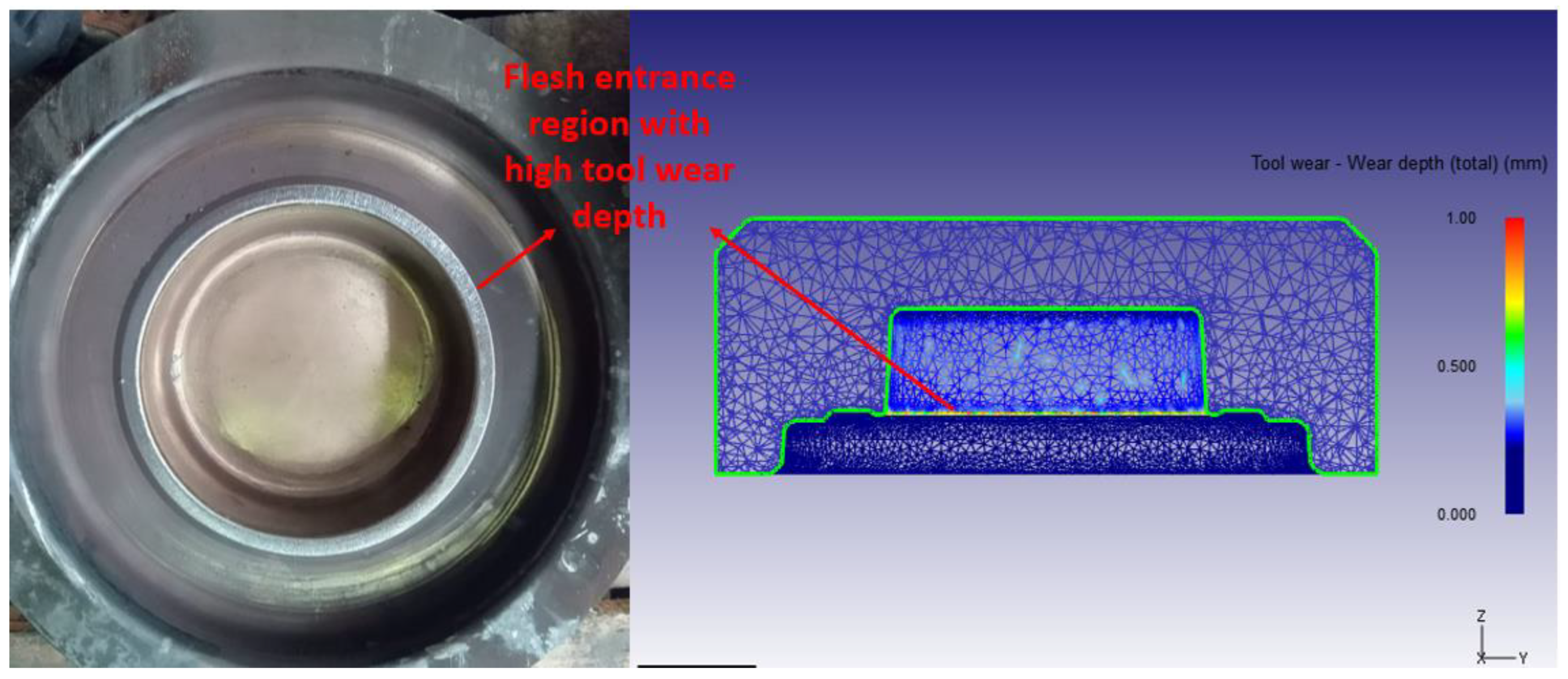
The developed process model was also able to predict accurately the wear pattern on the tool. Figure 13 (left) shows that the wear depth on the flash entrance was higher in the actual tool after 300 cycles. The process model was able to predict the region that is more venerable to wear, as shown in Figure 13 (right).
Based on these three comparisons, it is possible to check that the developed process model accurately predicts the material flow and tool behavior in hot forging of the 18CrNiMo7-6 pinion shaft, and it can be further used to optimize the process.
3. Analysis of Near-Net-Shape Die Design
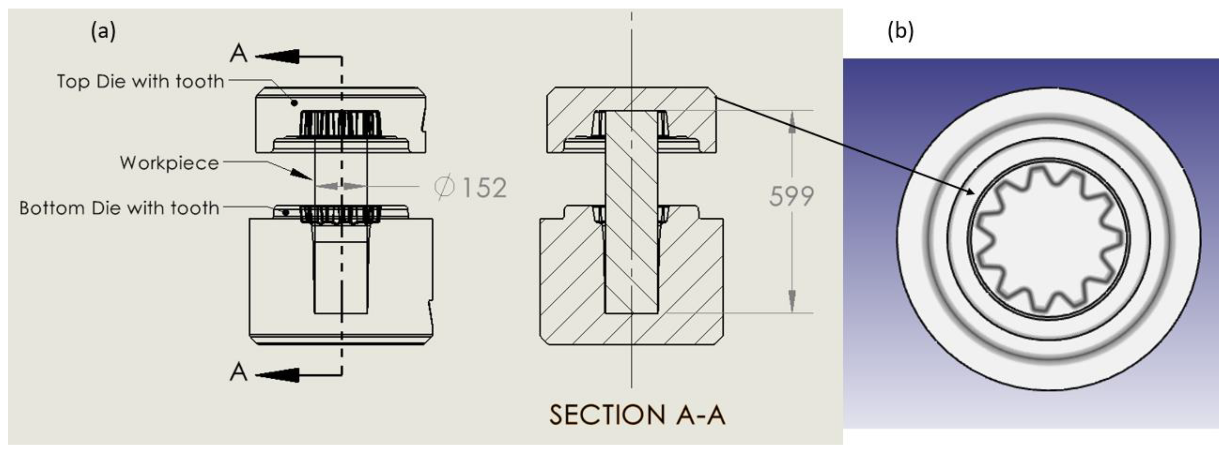
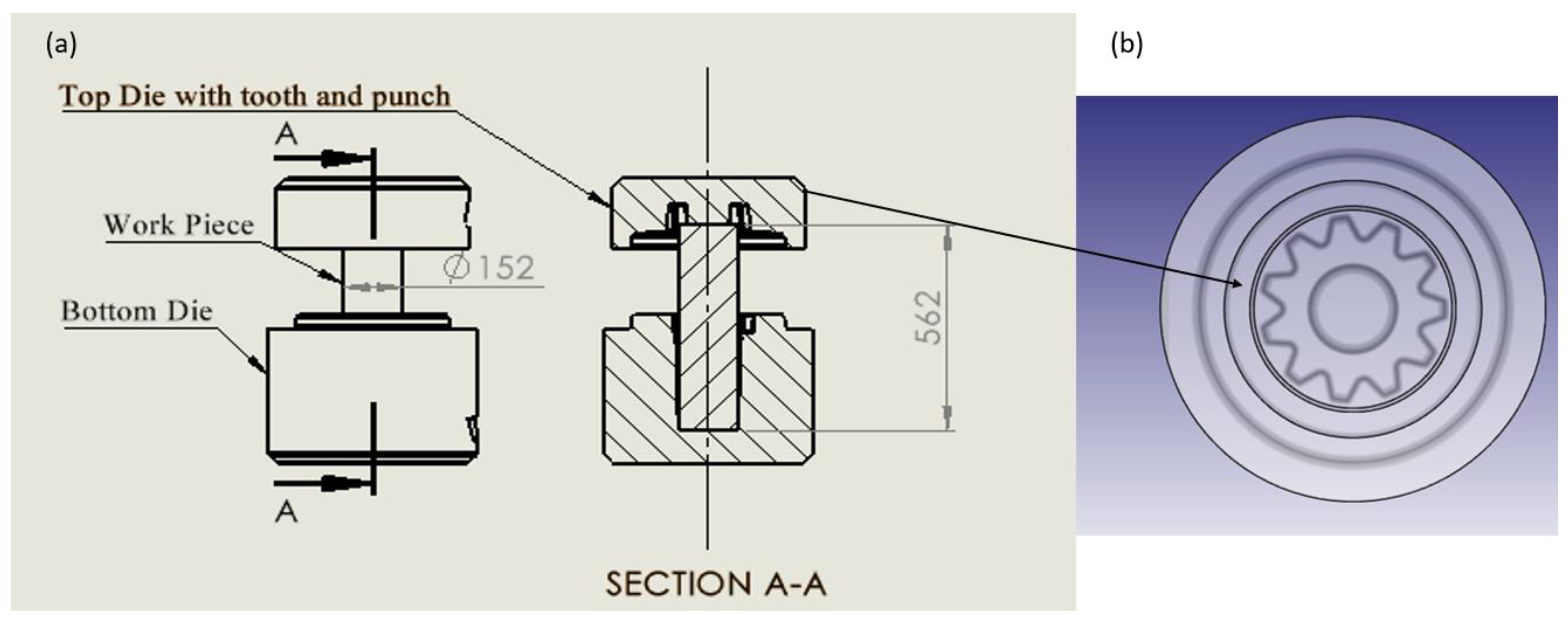
The validated numerical process model was used to further analyze two new near-net-shape top die designs. A top die with a pinion gear profile incorporated and a second top die with an additional punch were analyzed using the developed process model, as shown in Figure 14 and Figure 15, respectively. The workpiece volume was modified with different workpiece lengths compared to the length of the workpiece in the actual process for both processes, as the machining step can be avoided as it can obtain the final near-net product.
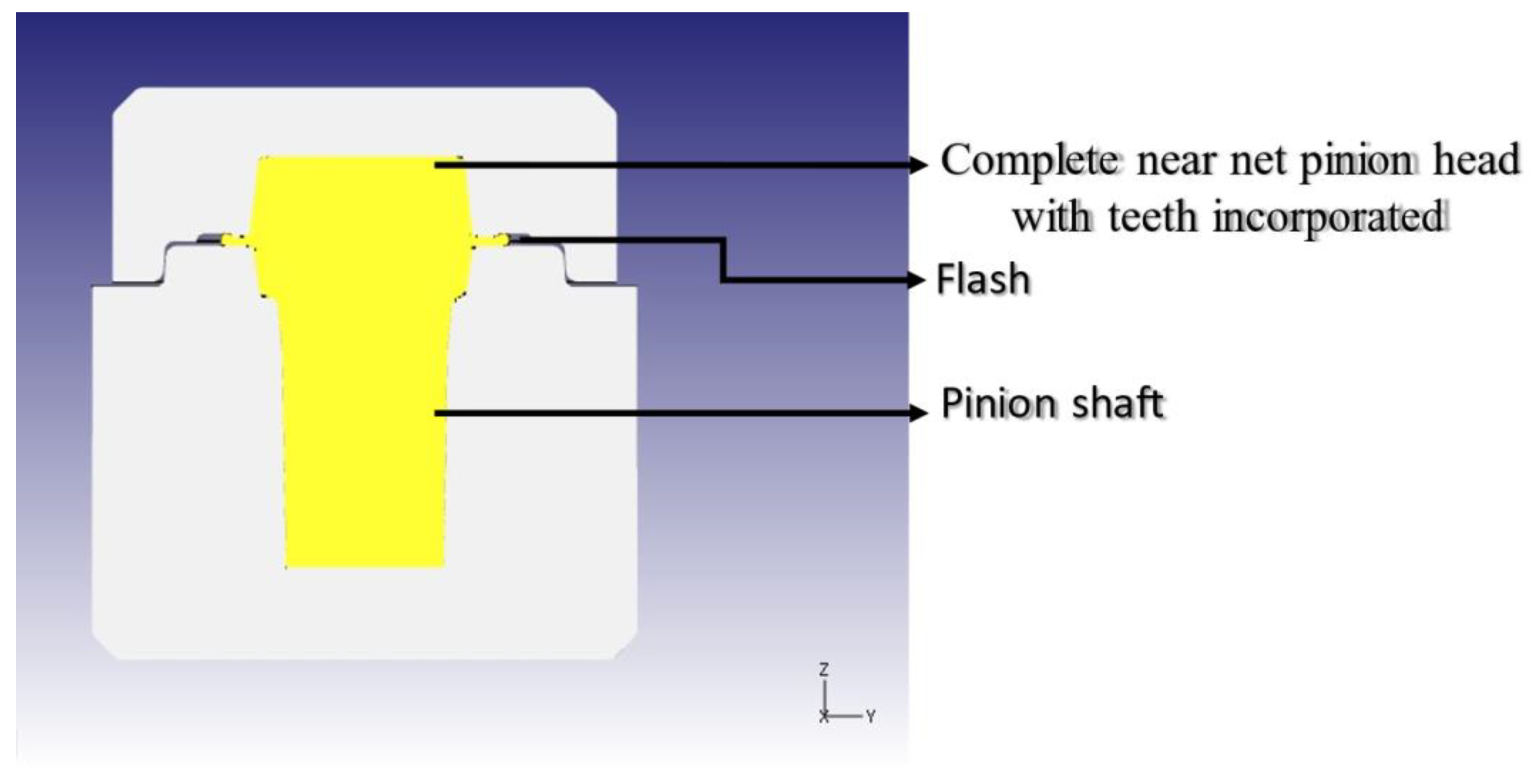
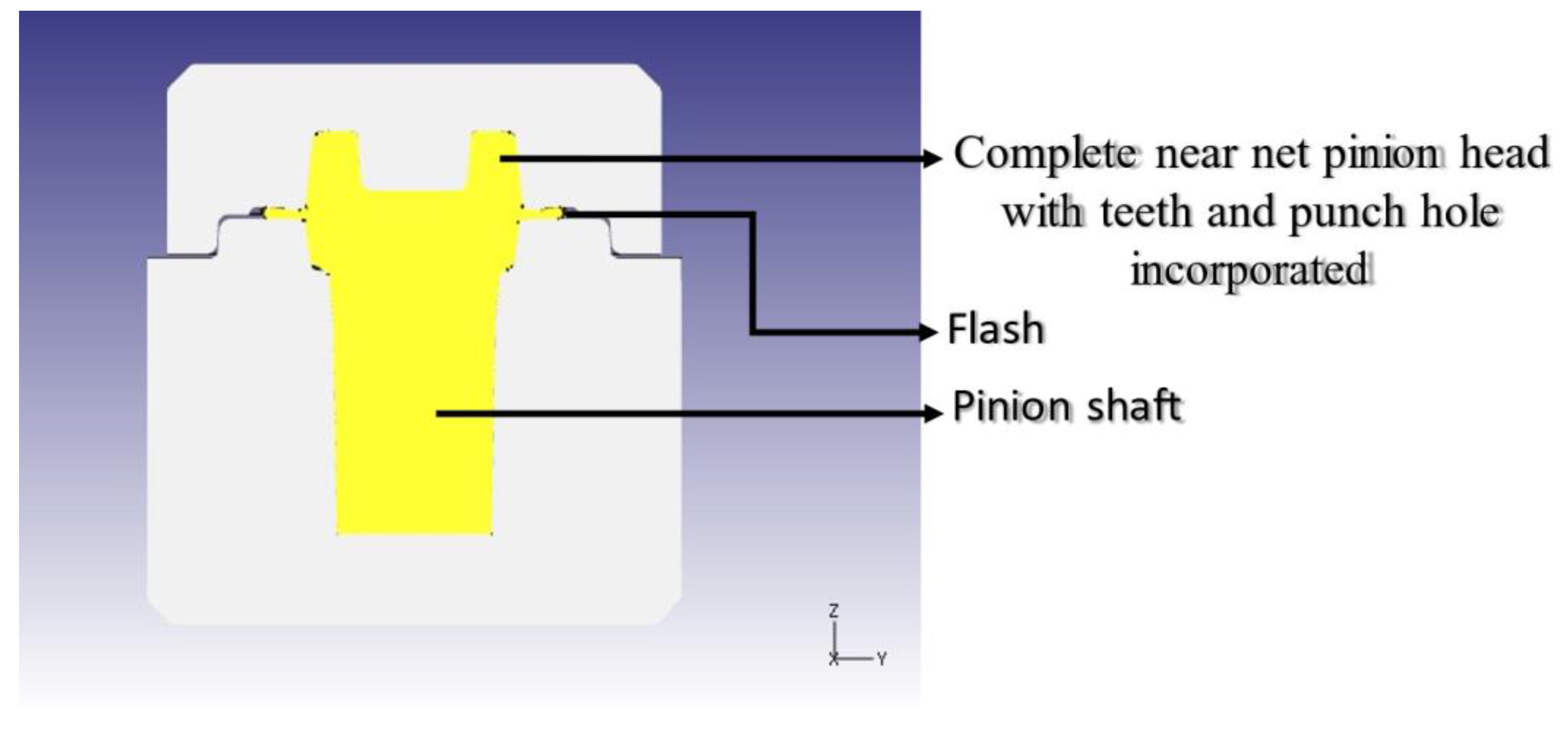
The process model inputs for DEFORM 3D® for studying the two near-net-shape dies were kept the same as for the actual forging process. The same hammer energy and blow table were used at the beginning of the process. It was found that the process model with just the gear teeth incorporated into the top die was able to fill the die cavity with the same number of blows as the actual process and the die with the punch took one extra blow to fill the die cavity, as shown in Figure 16 and Figure 17, respectively.
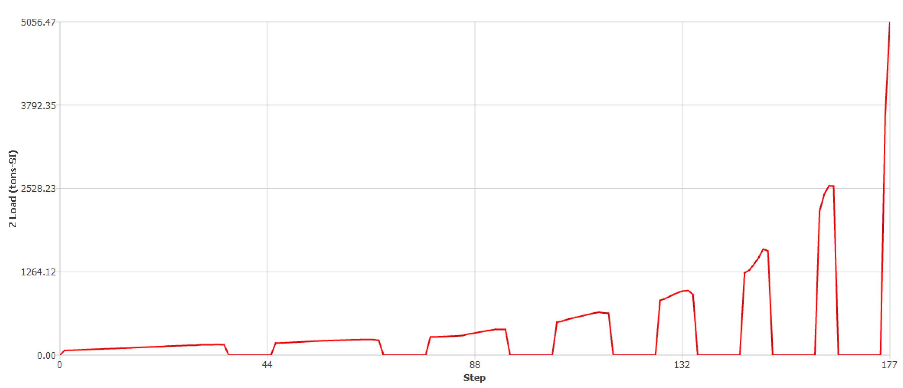
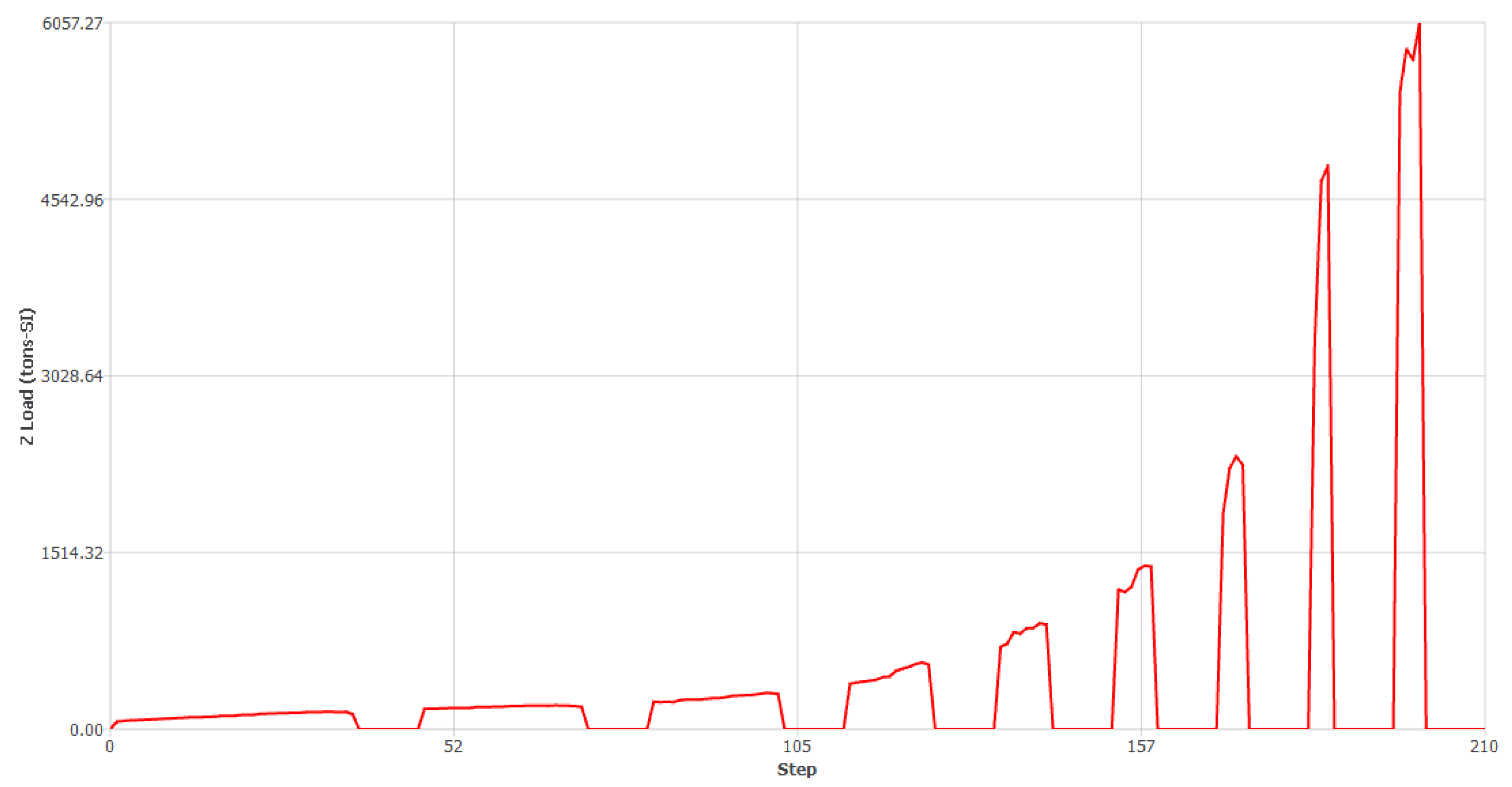
Consider the appropriately chosen parameters and data provided by the company for the current case, employing them in the simulation process (mesh, geometries of the dies and billets, hammer process considerations, and other parameters). Figure 18 depicts the load vs. steps linked to the simulation illustrated in Figure 16; the same situation takes place for Figure 17 and Figure 19.
4. Results and Discussion
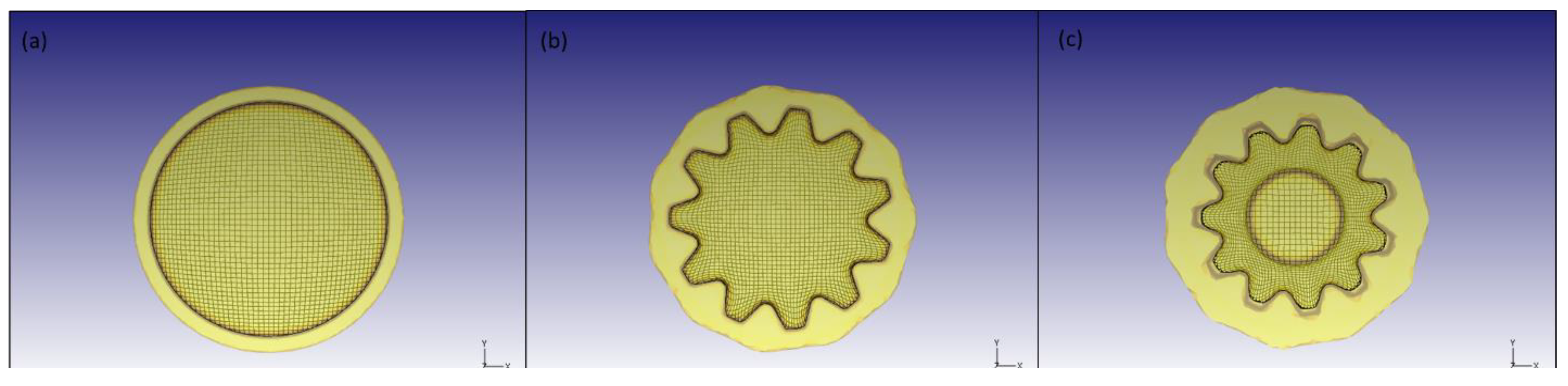
The main advantage of near-net-shape forging is the reduction in the machining steps involved in the entire manufacturing process. Figure 20 shows a comparison of the deformed grid pattern of the pinion head from the top view. In the current process, the forged pinion head must be machined to incorporate the gear teeth in the head, which will result in reducing the flow line shown in Figure 20a, which would decrease the mechanical properties of the final part; whereas the near-net-shape forged pinion head with incorporated gear teeth will have higher mechanical properties, improving the directional resistance and fatigue life of the component due to deformed grid lines from the forging, as shown in Figure 20b,c.
Die stress analysis and wear depth calculations were performed for the two top die designs and compared with the actual top die predictions to see if there is an increase in load and wear rate in the near-net-shape die design forging process. For the die stress analysis, the step that had the highest load on the top die was selected and a new die stress study was generated for both designs. In the case of the teeth incorporated into the top die, the tool experiences a maximum load of 5056 tons during the flash formation at the eighth blow, as shown in Figure 16. For the die with a punch, the maximum load is 6057 tons, as shown in Figure 17.
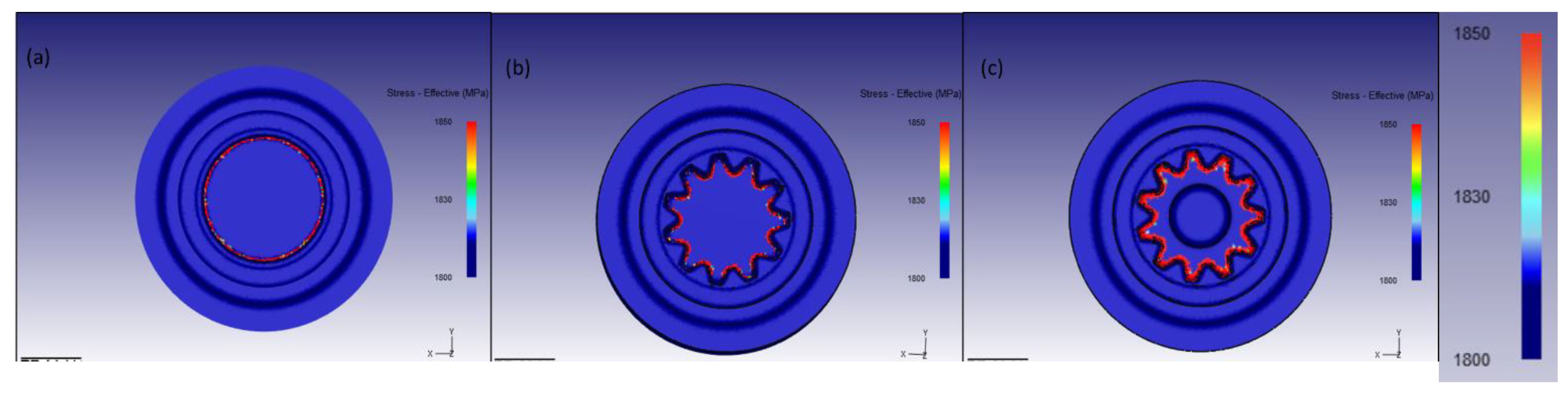
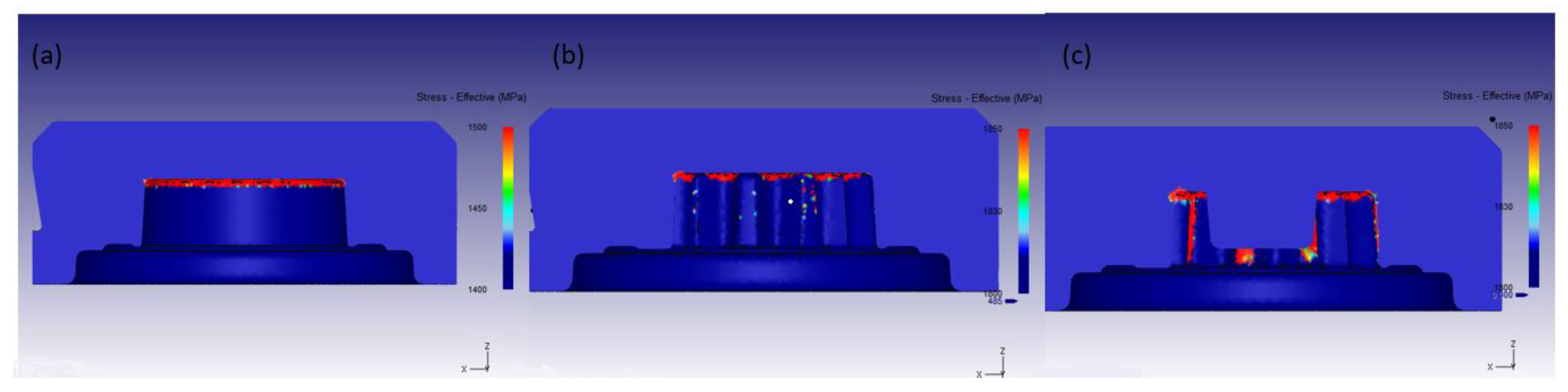
Figure 21 and Figure 22 (lateral view) show the comparison of the effective stress distribution in the top die. The red region in Figure 21 and Figure 22 shows the spot where the stress is higher, demonstrating that the thickness of the red region increases gradually from the actual die to the die with a punch. The number of cycles the top die can perform without cracking decreases as it moves from the left to the right.
Once again, the Archard wear model was used to analyze the wear depth pattern in the new near-net-shape top dies. Figure 23 shows the comparison of wear depth patterns between the actual top die and the two near-net-shape-proposed dies. It is possible to see the wear pattern in the flash opening section in all the dies, but it is more significant in the die with a punch, as shown in Figure 23c. The wear depth for the near-net-shape dies is, in general, higher than the actual tool as there is more sliding motion between the teeth profile in the die, punch, and workpiece material. As the maximum load, die stress, and wear depth are higher in the two near-net-shape top dies compared to the actual die design, it is expected that the life span of the dies will be fewer than 300 cycles, which is the life cycle of the current top die before cracking appears. The possible solution to the die life in this case should be an improvement with an appropriate and superficial heat treatment of the upper die to benefit from more cycles and to maintain the advantage to have better properties in the forged part of the pinion shaft and gain in the quantity of raw material, which are the main goals expected for the company in these results.
5. Conclusions
A numerical simulation process model for hot forging of 18CrNiMo7-6 steel was developed using commercially available DEFORM 3D software . The developed process model was validated by comparing the numerical prediction with the experimental measurements. The following comparisons were made: (1) the metal flow numerical predictions and the metal flow lines from the experiment; (2) the die stress prediction with the crack formation, as careful attention expected for this geometry; (3) the tool wear pattern using the Archard wear model. Based on these comparisons, it was found that the developed numerical process model was able to represent closely the actual forging process and the developed process model can be further used to analyze and improve the process efficiency.
The validated process model examined two near-net top die designs in DEFORM 3D using the established process model. Based on the post-processing evaluation of these two die designs, the following conclusions were made:
- The new proposed tooling designs incorporating the teeth gear resulted in 10 to 15% less feedstock material needed to form the near-net-shape final part.
- The FEM forging process simulation was confirmed and approved with the profile of hardness measurements and grain flow orientation (metallography) of the actual geometry, indicating improved mechanical properties.
- The top die design with teeth incorporated the same number of blows to fill the die cavity while experiencing higher die loads at the final blow. The die with both the teeth and punch design took one extra blow to fill the die cavity while experiencing an even higher die load than the die with just the teeth design. This could be an expected drawback of changes in geometry, but with considerable advantages in the new geometry, resulting in less machining, savings on raw material, and improvements in fatigue life and directional resistance in the teeth area, which are of great importance to the company.
- Based on the predicted higher die stresses and wear experienced by the two near-net-shape dies, caution with the die life is required and a special die surface treatment is suggested for the company for improvement and reliability, even considering it as a drawback, which is a common situation in the hot forging process.
- In the two new proposed designs, if the geometry of the teeth is obtained close to the final required shape by forging, skipping the machining process in the manufacturing of the teeth could be considered. A smaller volume of the incoming material can be considered, and the probability of distortions, due to the presence of the residual stresses after subsequent surface treatments, such as carburizing, will be reduced.
Author Contributions
Conceptualization, C.C.Y.; methodology, N.R.; software, N.R.; validation, R.A.d.S.; formal analysis, W.Z.M.; investigation, C.C.Y.; resources, W.Z.M.; data curation, R.A.d.S.; writing—original draft preparation, N.R.; writing—review and editing, C.C.Y.; visualization, R.A.d.S.; supervision, R.A.d.S.; project administration, W.Z.M.; funding acquisition, W.Z.M. All authors have read and agreed to the published version of the manuscript.
Funding
The authors would also like to acknowledge the financial support of the project from the Loewy Institute at Lehigh University.
Data Availability Statement
Additional data can be provided upon request.
Acknowledgments
The authors would like to thank Forja Bahia Company and its engineering team for the experimental part of the project. We would like to acknowledge Ramon Medeiros for his input during the development of the process numerical model.
Conflicts of Interest
The authors declare no conflict of interest.
References
- Rajiev, R.; Sadagopan, P.; Prakash, R.S. Study on investigation of hot forging die wear analysis—An industrial case study. Mater. Today Proc. 2020, 27, 2752–2757. [Google Scholar] [CrossRef]
- Pandya, V.A.; George, P.M. Preform optimization for the anchor shackle during closed die forging process on one ton hammer. Mater. Today Proc. 2021, 47, 3256–3262. [Google Scholar] [CrossRef]
- Pandya, V.A.; George, P.M. Effect of preform design on forging load and effective stress during closed die hot forging process of pin. Mater. Today Proc. 2021, 44, 106–112. [Google Scholar] [CrossRef]
- Behrens, B.-A.; Volk, W.; Maier, D.; Scandola, L.; Ott, M.; Brunotte, K.; Büdenbender, C.; Till, M. A combined numerical and experimental investigation on deterministic deviations in hot forging processes. Procedia Manuf. 2020, 47, 295–300. [Google Scholar] [CrossRef]
- Hsu, C.-C.; Chiu, H.-Y.; Liao, C.-C.; Fuh, Y.-K. An investigation on deformation mechanism of non-standard gear teeth forming in the hot impression forging of multicore cable cutter. J. Manuf. Process. 2020, 54, 158–168. [Google Scholar] [CrossRef]
- Qin, S.; Zhang, C.; Zhang, B.; Ma, H.; Zhao, M. Effect of carburizing process on high cycle fatigue behavior of 18CrNiMo7-6 steel. J. Mater. Res. Technol. 2022, 36, 1136–1149. [Google Scholar] [CrossRef]
- Huang, X.; Zang, Y.; Ji, H.; Wang, B.; Duan, H. Combination gear hot forging process and microstructure optimization. J. Mater. Res. Technol. 2022, 19, 1242–1259. [Google Scholar] [CrossRef]
- Lee, Y.; Yoon, E.; Nho, T.; Moon, Y. Microstructure control of ferrous driven part fabricated by warm precision forming. Procedia Manuf. 2018, 15, 404–410. [Google Scholar] [CrossRef]
- Böhme, S.A.; Szanti, G.; Keski-Rahkonen, J.; Komssi, T.; Santaella, J.G.; Vinogradov, A. Tooth flank fracture—An applied fatigue study of case hardened bevel gears. Eng. Fail. Anal. 2022, 132, 105911. [Google Scholar] [CrossRef]
- Landgrebe, D.; Sterzing, A.; Lahl, M.; Milbrandt, M.; Taubert, A.M. Hot forming of large spur gears. Procedia Eng. 2017, 207, 615–620. [Google Scholar] [CrossRef]
- Brinksmeier, E.; Lübben, T.; Fritsching, U.; Cui, C.; Rentsch, R.; Sölter, J. Distortion minimization of disks for gear manufacture. Int. J. Mach. Tools Manuf. 2011, 51, 331–338. [Google Scholar] [CrossRef]
- Bambach, M.; Imran, M.; Sizova, I.; Buhl, J.; Gerster, S.; Herty, M. A soft sensor for property control in multi-stage hot forming based on a level set formulation of grain size evolution and machine learning. J. Adv. Ind. Manuf. Eng. 2021, 2, 100041. [Google Scholar] [CrossRef]
- Chastel, Y.; Caillet, N.; Bouchard, P.-O. Quantitative analysis of the impact of forging operations on fatigue properties of steel components. J. Mater. Process. Technol. 2006, 177, 202–205. [Google Scholar] [CrossRef]
- Fu, P.; Zhan, K.; Jiang, C. Micro-structure and surface layer properties of 18CrNiMo7-6 steel after multistep shot peening. Mater. Des. 2013, 51, 309–314. [Google Scholar] [CrossRef]
- Pavan, A.H.V.; Vikrant, K.S.N.; Swamy, M.; Jayaraman, G. Root cause analysis of bowl-mill pinion shaft failures. Case Stud. Eng. Fail. Anal. 2013, 1, 103–109. [Google Scholar] [CrossRef]
- Mulutinovic, M.; Balos, S.; Plancak, M.; Movrin, D. Comparison of some mechanical properties and micro-topography of a component with non-axisymmetric geometry manufactured by cold orbital and hot forging. J. Mater. Process. Technol. 2017, 249, 179–192. [Google Scholar] [CrossRef]
- Kanani, J.B.; Lalwani, D.I. An experimental and FEA investigation of near-net-shape cold forging of spur gear. Mater. Today Proc. 2021, 44, 92–98. [Google Scholar] [CrossRef]
- Soranansri, P.; Yanil, S.; Sirivedin, K. Finite element modeling of shrink-fit design for improvement of die-service life in hot forging process of a bevel gear. Mater. Today Proc. 2019, 17, 1711–1719. [Google Scholar] [CrossRef]
- Renault, C.; Churyumov, A.Y.; Pozdniakov, A.V.; Churyumova, T.A. Microstructure and hot deformation behavior of FeMnAlCMo steel. J. Mater. Res. Technol. Process. 2020, 9, 4440–4449. [Google Scholar] [CrossRef]
- Equbal, M.I.; Kumar, R.; Shamim, M.; Ohdar, R.K. A grey-based Taguchi method to optimize hot forging process. Procedia Mater. Sci. 2014, 6, 1495–1504. [Google Scholar] [CrossRef]
- Bai, Q.; Lin, J.; Jiang, J.; Dean, T.; Zou, J.; Tian, G. A study of direct forging process for powder superalloys. Mater. Sci. Eng. A 2015, 621, 68–75. [Google Scholar] [CrossRef]
- How, C.K.J.; Behdinan, K. Neutral networks with input dimensionality reduction for efficient temperature distribution prediction in a warm stamping process. J. Appl. Comput. Mech. 2022, 8, 1431–1444. [Google Scholar] [CrossRef]
- Yikui, X.; Qicheng, W.; Zikun, C.; Xiaodong, W.; Hui, L.; Zhongying, W. Recrystallization Mechanism and processing map of 18CrNiMo7-6 alloy steel during hot deformation. Metals 2022, 12, 838. [Google Scholar] [CrossRef]
- Giardini, C.; Ceretti, E.; Maccarini, G.; Bugini, A. Friction and Wear in hot forging. Int. J. Form. Process. 2001, 4, 57–72. [Google Scholar] [CrossRef]
- Pan, H.; Wang, Z.; Zhang, J.; Li, J.; Wei, G.; Qiao, B.; Liu, L.; Li, J.; Zhao, Y.; Wang, Z.; et al. The effects of Q&P on microstructures and mechanical properties of a 18CrNiMo7-6 steel. Mater. Sci. Eng. A 2022, 861, 144374. [Google Scholar] [CrossRef]
Figure 1.
The hammering process flow.

Figure 2.
The sequence of the manufacturing process for the pinion shaft.

Figure 3.
Dispositions of the cuts to metallography of raw material and forged part.

Figure 4.
Schematic representation of 18CrNiMo pinion shaft forging process. Dimensions in mm.

Figure 5.
(a) Top die load exerted by the workpiece during flash formation, (b) drawing of the forged part (dimensions in mm).
Figure 5.
(a) Top die load exerted by the workpiece during flash formation, (b) drawing of the forged part (dimensions in mm).

Figure 6.
(a) Deformed grid pattern in the forging FEM simulation, (b) Metal flow pattern of the circled portion zoomed in, (c) Metallography of pinion shaft head after forging, showing metal flow lines.
Figure 6.
(a) Deformed grid pattern in the forging FEM simulation, (b) Metal flow pattern of the circled portion zoomed in, (c) Metallography of pinion shaft head after forging, showing metal flow lines.

Figure 7.
Micrography of the pinion shaft head after forging in the same area of the grain flow shown in Figure 6.
Figure 7.
Micrography of the pinion shaft head after forging in the same area of the grain flow shown in Figure 6.

Figure 8.
Micrography of the pinion shaft head near the flash area after forging.

Figure 9.
The markings from the Brinell hardness test.

Figure 10.
Force interpolation on the top die at flash formation.

Figure 11.
A cross-section depicting the stress distribution at maximum load: (a) Effective stress, (b) Maximum principal stress.
Figure 11.
A cross-section depicting the stress distribution at maximum load: (a) Effective stress, (b) Maximum principal stress.

Figure 12.
Comparison of cracking with stress distribution: (a) Actual top die showing crack, (b) Effective stress distribution in the top die (cross-section).
Figure 12.
Comparison of cracking with stress distribution: (a) Actual top die showing crack, (b) Effective stress distribution in the top die (cross-section).

Figure 13.
Tool wear pattern: (Left) Actual top die after 300 cycles, (Right) Wear depth distribution pattern from the numerical model.
Figure 13.
Tool wear pattern: (Left) Actual top die after 300 cycles, (Right) Wear depth distribution pattern from the numerical model.

Figure 14.
(a) Schematics of near-net-shape forging, (b) Top die with gear teeth incorporated. Dimensions in mm.
Figure 14.
(a) Schematics of near-net-shape forging, (b) Top die with gear teeth incorporated. Dimensions in mm.

Figure 15.
(a) Schematics of near-net-shape forging, (b) Top die with gear teeth and punch. Dimensions in mm.
Figure 15.
(a) Schematics of near-net-shape forging, (b) Top die with gear teeth and punch. Dimensions in mm.

Figure 16.
Near-net pinion shaft with teeth formation incorporated.

Figure 17.
Near-net pinion shaft with teeth and multilevel head.

Figure 18.
Plotted Load vs. Step for near-net pinion shaft with teeth formation incorporated.

Figure 19.
Plotted Load vs. Step for Near-net pinion shaft with teeth and multilevel head.

Figure 20.
Deformed grid pattern flow line in the forged pinion head from top view: (a) Actual forged head, (b) Forged head with teeth, (c) Forged head with teeth and punched hole.
Figure 20.
Deformed grid pattern flow line in the forged pinion head from top view: (a) Actual forged head, (b) Forged head with teeth, (c) Forged head with teeth and punched hole.

Figure 21.
Comparison of effective stress in MPa: (a) Actual top die, (b) Top die with teeth, (c) Top die with punch.
Figure 21.
Comparison of effective stress in MPa: (a) Actual top die, (b) Top die with teeth, (c) Top die with punch.

Figure 22.
Comparison of effective stress in MPa (with lateral view): (a) Actual top die, (b) Top die with teeth, (c) Top die with punch.
Figure 22.
Comparison of effective stress in MPa (with lateral view): (a) Actual top die, (b) Top die with teeth, (c) Top die with punch.

Figure 23.
Comparison of wear depth pattern in mm: (a) Actual top die, (b) Top die with the teeth, (c) Top die with a punch hole.
Figure 23.
Comparison of wear depth pattern in mm: (a) Actual top die, (b) Top die with the teeth, (c) Top die with a punch hole.


Table 1.
Chemical composition of the tested steel (% values).
| 18CrNiMo 7-6 steel | C | Si | Mn | P | S | Cr | Ni | Mo | Al | Cu |
| 0.18 | 0.28 | 0.76 | 0.014 | 0.013 | 1.78 | 1.62 | 0.29 | 0.026 | 0.15 |
Table 2.
Blow table of the actual process.
| Blow (#) | Blow Strain (%) | Energy (J) | Efficiency (%) | Dwell (S) |
|---|---|---|---|---|
| 1 | 65 | 7.8 × 10⁴ | 1 | 1 |
| 2 | 75 | 9 × 10⁴ | 1 | 1 |
| 3 | 85 | 1.02 × 10⁵ | 1 | 1 |
| 4 | 95 | 1.14 × 10⁵ | 1 | 1 |
| 5 | 95 | 1.14 × 10⁵ | 1 | 1 |
| 6 | 95 | 1.14 × 10⁵ | 1 | 1 |
| 7 | 95 | 1.14 × 10⁵ | 1 | 1 |
| 8 | 95 | 1.14 × 10⁵ | 1 | 1 |
Disclaimer/Publisher’s Note: The statements, opinions and data contained in all publications are solely those of the individual author(s) and contributor(s) and not of MDPI and/or the editor(s). MDPI and/or the editor(s) disclaim responsibility for any injury to people or property resulting from any ideas, methods, instructions or products referred to in the content. |
© 2023 by the authors. Licensee MDPI, Basel, Switzerland. This article is an open access article distributed under the terms and conditions of the Creative Commons Attribution (CC BY) license (https://creativecommons.org/licenses/by/4.0/).
Share and Cite
MDPI and ACS Style
Rajendran, N.; Yurgel, C.C.; Misiolek, W.Z.; Alves de Sousa, R. Hot Forging Die Design Optimization Using FEM Analysis for Near-Net Forming of 18CrNiMo7-6 Steel Pinion Shaft. Metals 2023, 13, 815. https://doi.org/10.3390/met13040815
AMA Style
Rajendran N, Yurgel CC, Misiolek WZ, Alves de Sousa R. Hot Forging Die Design Optimization Using FEM Analysis for Near-Net Forming of 18CrNiMo7-6 Steel Pinion Shaft. Metals. 2023; 13(4):815. https://doi.org/10.3390/met13040815
Chicago/Turabian StyleRajendran, Nijenthan, Charles Chemale Yurgel, Wojciech Z. Misiolek, and Ricardo Alves de Sousa. 2023. "Hot Forging Die Design Optimization Using FEM Analysis for Near-Net Forming of 18CrNiMo7-6 Steel Pinion Shaft" Metals 13, no. 4: 815. https://doi.org/10.3390/met13040815
Note that from the first issue of 2016, this journal uses article numbers instead of page numbers. See further details here.