
Preparation of High-Purity Magnesium from Electrolytically Produced Crude Magnesium via Vacuum Distillation
 ,
,
Abstract
:1. Introduction
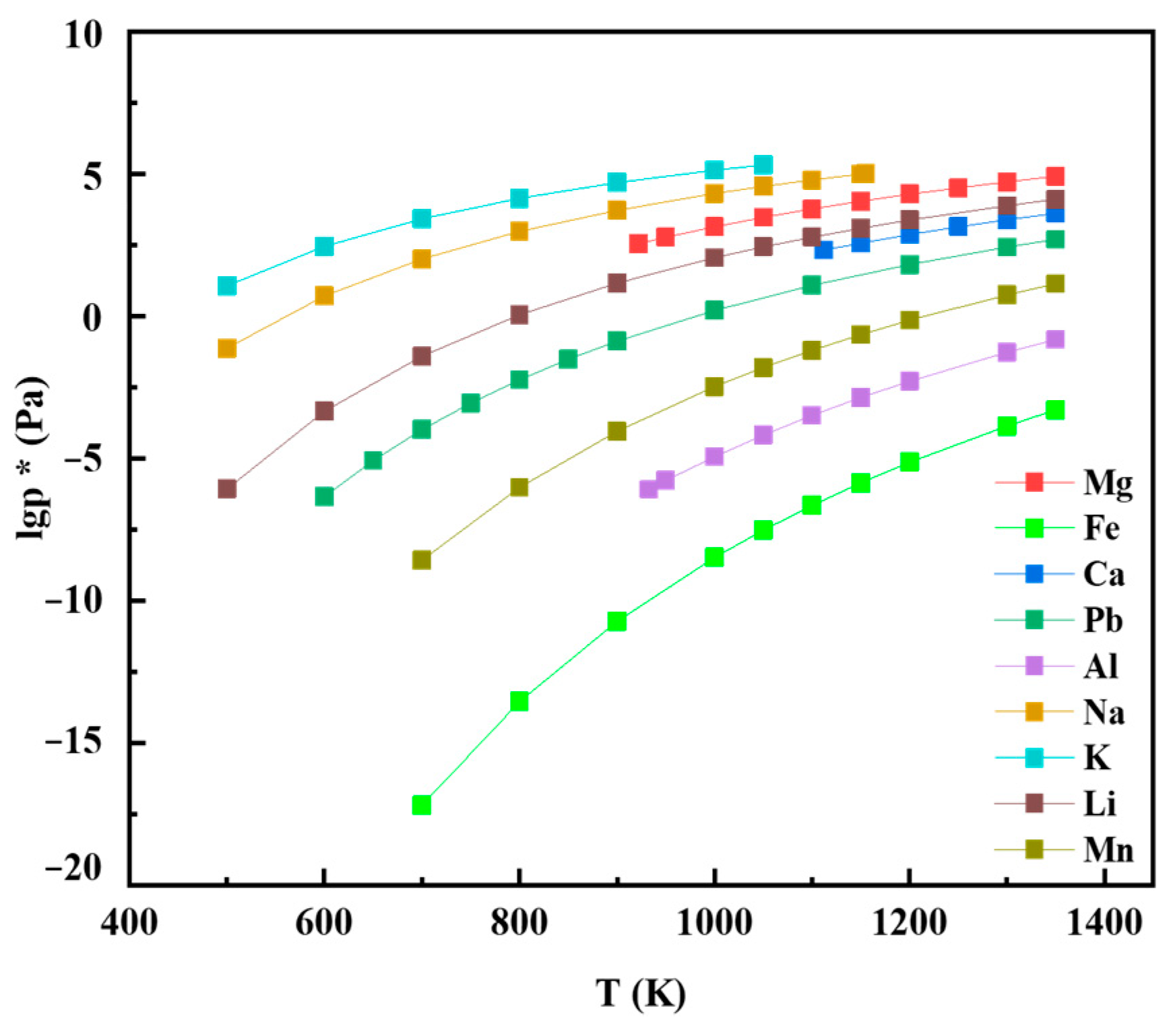
2. Theoretical Equilibrium Vapor Pressure of Vacuum Distillation
3. Experimental Procedures
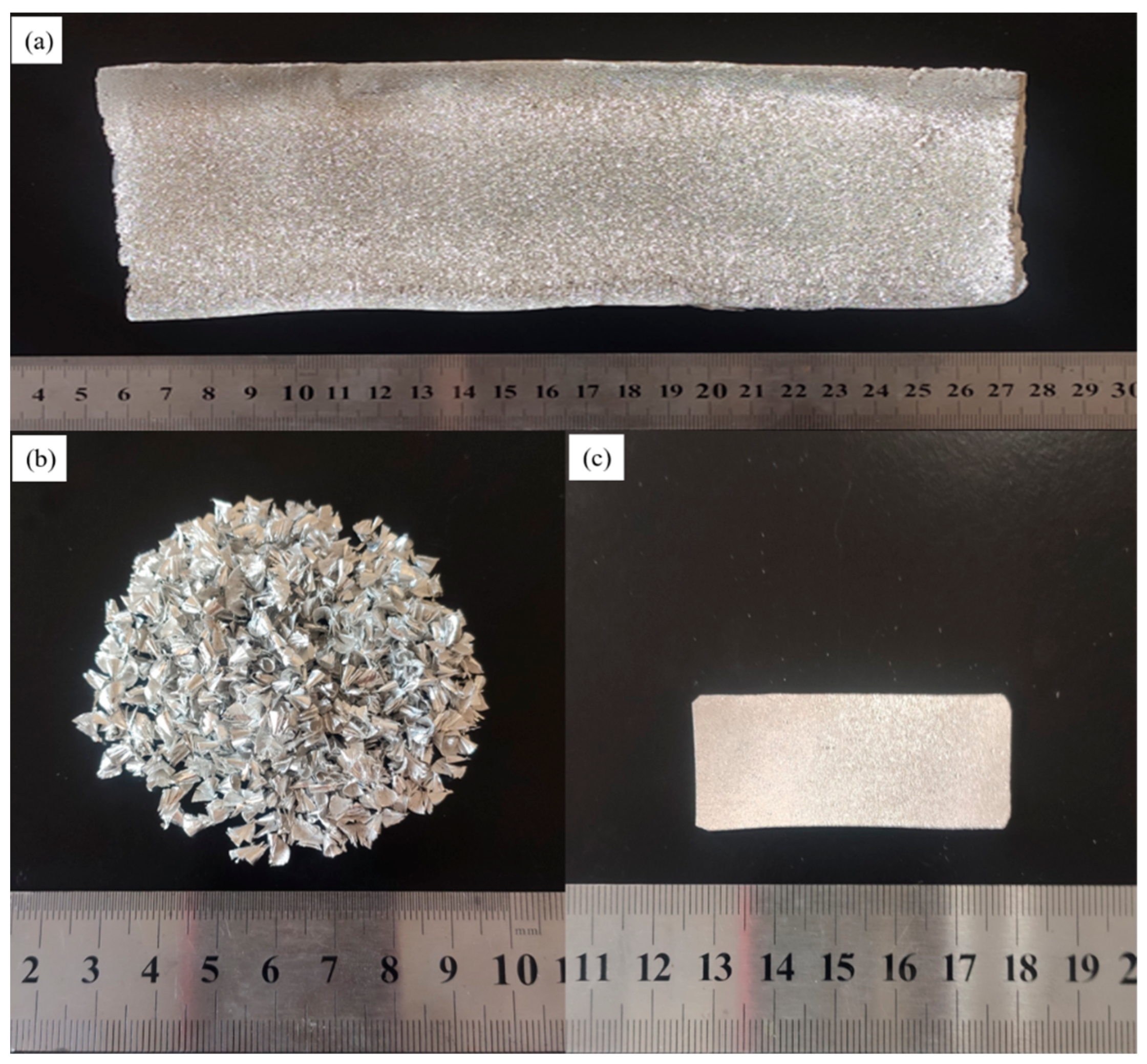
3.1. Sample Preparation
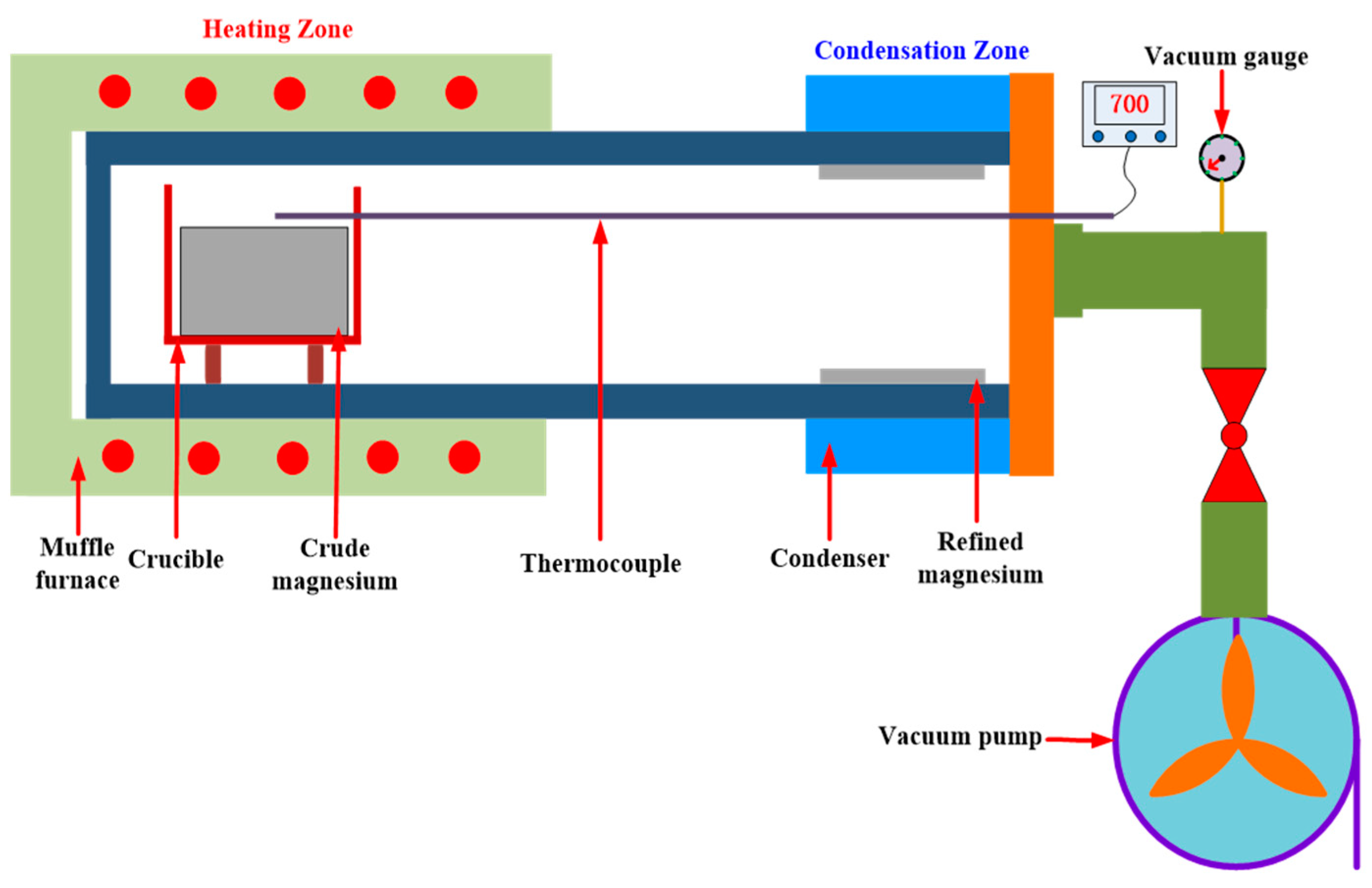
3.2. Vacuum Distillation Experiments
3.3. Sample Characterization
4. Results and Discussion
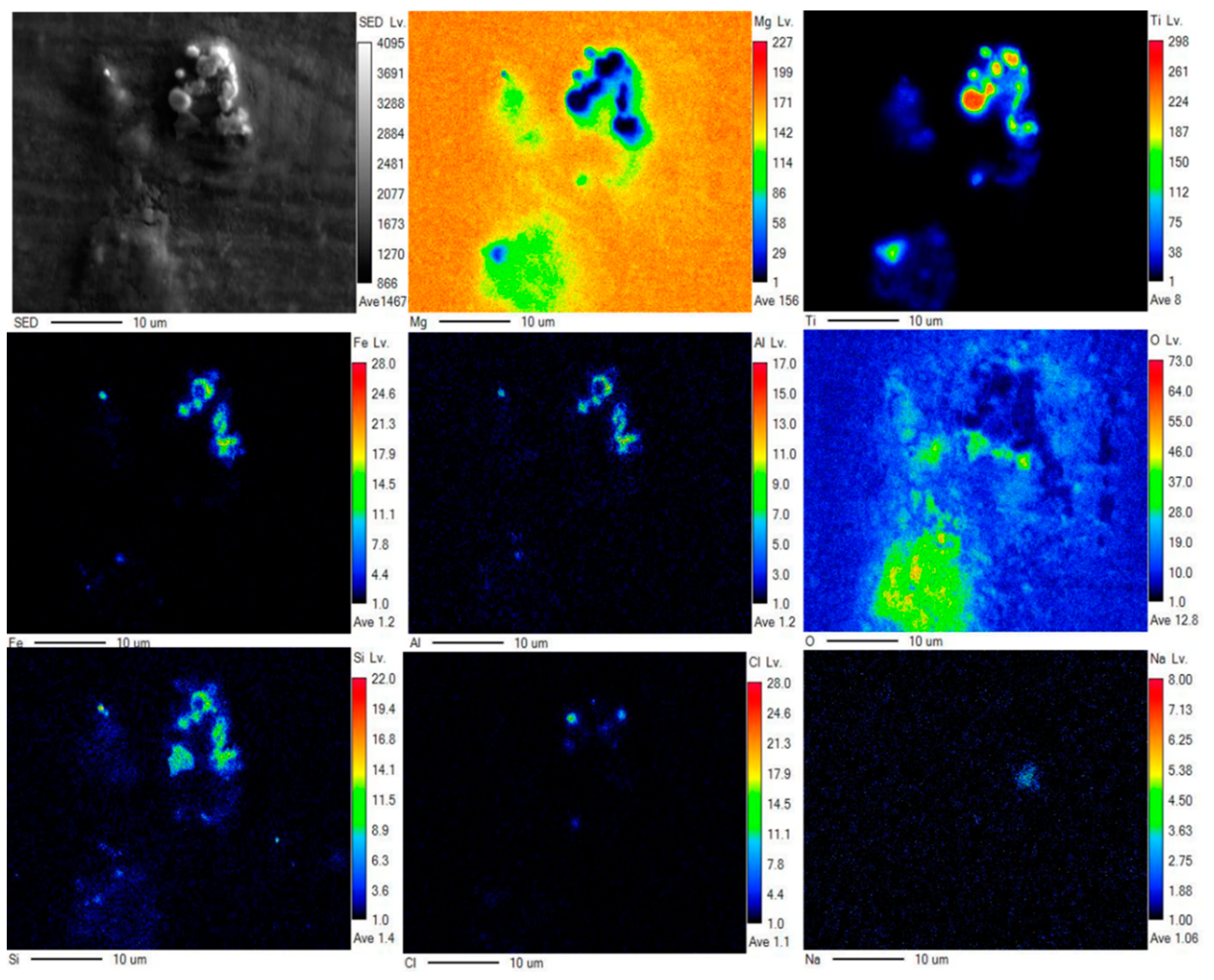
4.1. State of the Impurities in CM
4.2. Influence of the Distillation Process on the Quality of the Refined Mg
5. Conclusions
Author Contributions
Funding
Data Availability Statement
Acknowledgments
Conflicts of Interest
References
- Froes, F.H.; Eliezer, D.; Aghion, E. The science, technology, and applications of magnesium. JOM 1998, 50, 30–34. [Google Scholar] [CrossRef]
- Song, K.; Pan, F.S.; Chen, X.H.; Zhang, Z.H.; Tang, A.T.; She, J.; Yu, Z.W.; Pan, H.C.; Xu, X.Y. Effect of texture on the electromagnetic shielding property of magnesium alloy. Mater. Lett. 2015, 157, 73–76. [Google Scholar] [CrossRef]
- Li, S.; Yang, X.; Hou, J.; Du, W. A review on thermal conductivity of magnesium and its alloys. J. Magnes. Alloy. 2020, 8, 78–90. [Google Scholar] [CrossRef]
- Gray, J.E.; Luan, B. Protective coatings on magnesium and its alloys—A critical review. J. Alloys Compd. 2002, 336, 88–113. [Google Scholar] [CrossRef]
- Figueiredo, R.B.; Poggiali, F.S.J.; Silva, C.L.P.; Cetlin, P.R.; Langdon, T.G. The influence of grain size and strain rate on the mechanical behavior of pure magnesium. J. Mater. Sci. 2015, 51, 3013–3024. [Google Scholar] [CrossRef]
- Somekawa, H.; Mukai, T. Hall–Petch breakdown in fine-grained pure magnesium at low strain rates Metall. Mater. Trans. A 2014, 46, 894–902. [Google Scholar] [CrossRef]
- Kulekci, M.K. Magnesium and its alloys applications in automotive industry. Int. J. Adv. Manuf. Tech. 2007, 39, 851–865. [Google Scholar] [CrossRef]
- You, S.; Huang, Y.; Kainer, K.U.; Hort, N. Recent research and developments on wrought magnesium alloys. J. Magnes. Alloy. 2017, 5, 239–253. [Google Scholar] [CrossRef]
- Pan, F.; Yang, M.; Chen, X. A Review on casting magnesium alloys: Modification of commercial alloys and development of new Alloys. J. Mater. Sci. Technol. 2016, 32, 1211–1221. [Google Scholar] [CrossRef]
- Xia, X.; Chen, X.; Zhao, W.; Xue, H.; Liao, B.; Hur, B.; Wang, Z. Corrosion behavior of closed-cell AZ31 Mg alloy foam in NaCl aqueous solutions. Corros. Sci. 2014, 80, 247–256. [Google Scholar] [CrossRef]
- Luo, A.A. Recent magnesium alloy development for elevated temperature applications. Int. Mater. Rev. 2004, 49, 13–30. [Google Scholar] [CrossRef]
- Hort, N.; Huang, Y.; Kainer, K.U. Intermetallics in magnesium alloys. Adv. Eng. Mater. 2006, 8, 235–240. [Google Scholar] [CrossRef]
- Wulandari, W.; Brooks, G.; Rhamdhani, M.; Monaghan, B. Magnesium: Current and Alternative Production Routes. In Australian Conference on Chemical Engineering; University of Wollongong Australia: Wollongong, Australia, 2010. [Google Scholar]
- Pekguleryuz, M.; Mackenzie, L. (Eds.) Pilot Plant Demonstration of the Mintek Thermal Magnesium Process. In Proceedings of the Conference of Metallurgists, Montréal, QC, Canada, 1–4 October 2006. [Google Scholar]
- GB/T 3499-2011; Standard of the People’s Republic of China for Primary Magnesium Ingot. The Chinese Standards Committee: Beijing, China, 2011.
- Birbilis, N.; King, A.; Thomas, S.; Frankel, G.S.; Scully, J.R. Evidence for enhanced catalytic activity of magnesium arising from anodic dissolution. Electrochim. Acta 2014, 132, 277–283. [Google Scholar] [CrossRef]
- Duhaime, P.; Mercille, P.; Pineau, M. Electrolytic process technologies for the production of primary magnesium. Miner. Process Extr. Metall. Rev. 2002, 111, 53–55. [Google Scholar] [CrossRef]
- Du, J.; Han, W.; Peng, Y. Life cycle greenhouse gases, energy and cost assessment of automobiles using magnesium from Chinese Pidgeon process. J. Clean Prod. 2010, 18, 112–119. [Google Scholar] [CrossRef]
- Tian, Y.; Wang, L.; Yang, B.; Dai, Y.; Xu, B.; Wang, F.; Xiong, N. Comparative evaluation of energy and resource consumption for vacuum carbothermal reduction and Pidgeon process used in magnesium production. J. Magnes. Alloy. 2020, 10, 697–706. [Google Scholar] [CrossRef]
- Mohamed, S.R.; Friedrich, S.; Friedrich, B. Refning principles and technical methodologies to produce ultra-pure magnesium for high-tech applications. Metals 2019, 9, 85. [Google Scholar] [CrossRef]
- Inoue, M.; Iwai, M.; Matsuzawa, K.; Kamado, S.; Kojima, Y. Vacuum distillation refning and recycling of magnesium alloys. Mater. Sci. Forum. 2003, 419–422, 691–696. [Google Scholar] [CrossRef]
- Bolivar, R.; Friedrich, B. Magnesiothermic reduction from titanium dioxide to produce titanium powder. J. Sustain. Metall. 2019, 5, 219–229. [Google Scholar] [CrossRef]
- Choi, K.; Choi, H.; Sohn, I. Understanding the Magnesiothermic Reduction Mechanism of TiO2 to Produce Ti. Metall. Mater. Trans. B 2017, 48, 922–932. [Google Scholar] [CrossRef]
- Gao, F.; Nie, Z.; Yang, D.; Sun, B.; Liu, Y.; Gong, X.; Wang, Z. Environmental impacts analysis of titanium sponge production using Kroll process in China. J. Clean. Prod. 2018, 174, 771–779. [Google Scholar] [CrossRef]
- Krauter, N.; Eckert, S.; Gundrum, T.; Stefani, F.; Wondrak, T.; Khalilov, R.; Dimov, I.; Frick, P. Experimental Validation of an Inductive System for Magnesium Level Detection in a Titanium Reduction Reactor. Sensors 2020, 20, 6798. [Google Scholar] [CrossRef] [PubMed]
- Lee, T.H.; Okabe, T.H.; Lee, J.-Y.; Kim, Y.M.; Kang, J. Development of a novel electrolytic process for producing high-purity magnesium metal from magnesium oxide using a liquid tin cathode. J. Magnes. Alloy. 2021, 9, 1644–1655. [Google Scholar] [CrossRef]
- Yang, B.; Liang, D.; Xiong, N.; Tian, Y.; Xu, B.; Dai, Y. Effect of crystallization on purity of volatile metallic magnesium prepared from a one-step multi-region condensation process under vacuum condition. J. Magnes. Alloy. 2022, 10, 3281–3287. [Google Scholar] [CrossRef]
- Pan, F.S.; Chen, X.H.; Yan, T.; Liu, T.T.; Mao, J.J.; Luo, W.; Wang, Q.; Peng, J.; Tang, A.T.; Jiang, B. A novel approach to melt purification of magnesium alloys. J. Magnes. Alloy. 2016, 4, 8–14. [Google Scholar] [CrossRef]
- Park, J.; Jung, Y.; Kusumah, P.; Dilasari, B.; Ku, H.; Kim, H.; Kwon, K.; Lee, C.K. Room temperature magnesium electrorefining by using non-aqueous electrolyte. Met. Mater. Int. 2016, 22, 907–914. [Google Scholar] [CrossRef]
- Lee, J.H.; Nersisyan, H.; Huynh, T.N. Combustion-Alumino-Magnesiothermic Reduction of TiO2 to Produce a Ti-Rich Ingot. Metall. Mater. Trans. B 2022, 53, 3147–3158. [Google Scholar] [CrossRef]
- Inoue, M.; Doi, T.; Aida, T.; Matsuki, K.; Kamado, S.; Kojima, Y. Vacuum distillation refining and extrusion process of magnesium. Mater. Sci. Forum. 2005, 475–479, 513–516. [Google Scholar] [CrossRef]
- Lam, R.K.F.; Marx, D.R. Ultra High Purity Magnesium Vacuum Distillation Purification Method. U.S. Patent US 08/391,047, 10 December 1996. [Google Scholar]
- Zhang, X.; Friedrich, S.; Bernd, F. Separation behavior of arsenic and lead from antimony during vacuum distillation and zone refining. J. Mater. Res. Technol. 2020, 9, 4386–4398. [Google Scholar] [CrossRef]
- Revel, G.; Pastol, J.L.; Rouchaud, J.C.; Fromageau, R. Purification of Magnesium by Vacuum Distillation. Metall. Mater. Trans. B 1978, 9, 665–672. [Google Scholar] [CrossRef]
- Papirov, I.I.; Kravchenko, A.I.; Mazin, A.I.; Shiyan, A.V.; Virich, V.D. Impurity distribution in a magnesium sublimate. Inorg. Mater. 2015, 51, 563–565. [Google Scholar] [CrossRef]
- Mizuhara, K.; Inoue, M.; Aida, T.; Matsuzawa, K.; Aoyagi, N.; Miura, H. Preparation of ultra high purity magnesium sheet by vacuum distillation and extrusion. Trans. GIGAKU 2020, 7, 07004-1–07004-7. [Google Scholar] [CrossRef]
- Rodushkin, I.; Ruth, T.; Huhtasaari, Å. Comparison of two digestion methods for elemental determinations in plant material by ICP techniques. Anal. Chim. Acta 1999, 378, 191–200. [Google Scholar] [CrossRef]
- Mordike, B.L.; Ebert, T. Magnesium: Properties-applications-potential. Mater. Sci. Eng. A 2001, 302, 37–45. [Google Scholar] [CrossRef]
- Han, J.B.; Fu, D.X.; Guo, J.H.; Ji, Z.H.; Dou, Z.H.; Zhang, T.A. Nucleation and Condensation of Magnesium Vapor in Argon Carrier. Metals 2020, 10, 1441. [Google Scholar] [CrossRef]
- Wang, Y.C.; Tian, Y.; Qu, T.; Yang, B.; Dai, Y.; Sun, Y. Purification of Magnesium by Vacuum Distillation and its Analysis. Mater. Sci. Forum 2014, 788, 52–57. [Google Scholar] [CrossRef]
- Yong, D.; Bin, Y. Vacuum Metallurgy of Nonferrous Metal Materials; Metallurgical Industry Press: Beijing, China, 2000. [Google Scholar]
- Gesing, A.J.; Das, S.K. Use of Thermodynamic Modeling for Selection of Electrolyte for Electrorefining of Magnesium from Aluminum Alloy Melts. Metall. Mater. Trans. B 2017, 48, 132–145. [Google Scholar] [CrossRef]
- Liu, C.L.; Zhao, Q.W.; Sun, Z. Analysis of Magnesium Droplets Characteristics and Separation Performance in a Magnesium Electrolysis Cell Based on Multiphysical Modeling. Arab. J. Sci. Eng. 2018, 43, 5965–5976. [Google Scholar] [CrossRef]
- Tian, Y.; Zhang, X.P.; Qu, T.; Lyu, F.; Du, H.; Shi, L.; Yang, B.; Dai, Y.N. Technical research on vacuum distillation to purify magnesium to 99.99% purity. Mater. Res. Express 2021, 8, 056506. [Google Scholar] [CrossRef]


| Category | Al/% | Fe/% | Si/% | Ti/% | Cr/% | S/% | Cl/% | Na/% | Ni/% |
|---|---|---|---|---|---|---|---|---|---|
| Electrolytic process | 0.0243 | 0.0184 | 0.0072 | 0.0061 | 0.0015 | 0.0026 | 0.0106 | 0.0013 | 0.0011 |
| Mg9999 [15] | 0.002 | 0.002 | 0.002 | 0.0005 | - | - | - | - | 0.0003 |
| T/K | β (Pb) | β (Mn) | β (Al) | β (Cu) | β (Fe) | β (Ni) | β (Si) |
|---|---|---|---|---|---|---|---|
| 973 | 8.74 × 10⁻⁴ | 1.38 × 10⁻⁶ | 4.25 × 10⁻⁹ | 3.96 × 10⁻¹⁰ | 9.36 × 10⁻¹³ | 5.47 × 10⁻¹⁴ | 3.97 × 10⁻¹⁵ |
| 1023 [44] | 1.35 × 10⁻³ | 3.53 × 10⁻⁶ | 1.35 × 10⁻⁸ | 1.49 × 10⁻⁹ | 4.84 × 10⁻¹² | 3.54 × 10⁻¹³ | 2.96 × 10⁻¹⁴ |
| No. | Temperature/K | Holding Time/min | Pre-Distillation Mass/g | Condensed Mg Mass/g | Residual/g | Post-Distillation Pressure/Pa |
|---|---|---|---|---|---|---|
| 1 | 900 | 60 | 203.5 | 61.46 | 142.04 | 8.5 |
| 2 | 900 | 90 | 206.4 | 71.41 | 134.99 | 7.5 |
| 3 | 900 | 120 | 203.1 | 88.75 | 114.35 | 6.3 |
| 4 | 900 | 180 | 206.3 | 107.89 | 98.41 | 5.6 |
| 5 | 923 | 60 | 210.5 | 86.52 | 123.98 | 4.8 |
| 6 | 923 | 90 | 198.3 | 125.92 | 72.38 | 3.2 |
| 7 | 923 | 120 | 205.9 | 162.25 | 43.65 | 2.5 |
| 8 | 923 | 180 | 207.2 | 183.58 | 23.62 | 2.0 |
| 9 | 973 | 30 | 196.3 | 72.43 | 123.87 | 1.9 |
| 10 | 973 | 60 | 198.3 | 157.25 | 41.05 | 1.5 |
| 11 | 973 | 90 | 204.1 | 198.18 | 5.92 | 1.3 |
| 12 | 973 | 120 | 206.8 | 203.70 | 3.10 | 1.3 |
| 13 | 1023 | 30 | 201.3 | 111.92 | 89.38 | 1.7 |
| 14 | 1023 | 60 | 195.6 | 165.28 | 30.32 | 1.4 |
| 15 | 1023 | 90 | 206.3 | 202.79 | 3.51 | 1.3 |
| 16 | 1023 | 120 | 204.7 | 202.65 | 2.05 | 1.3 |
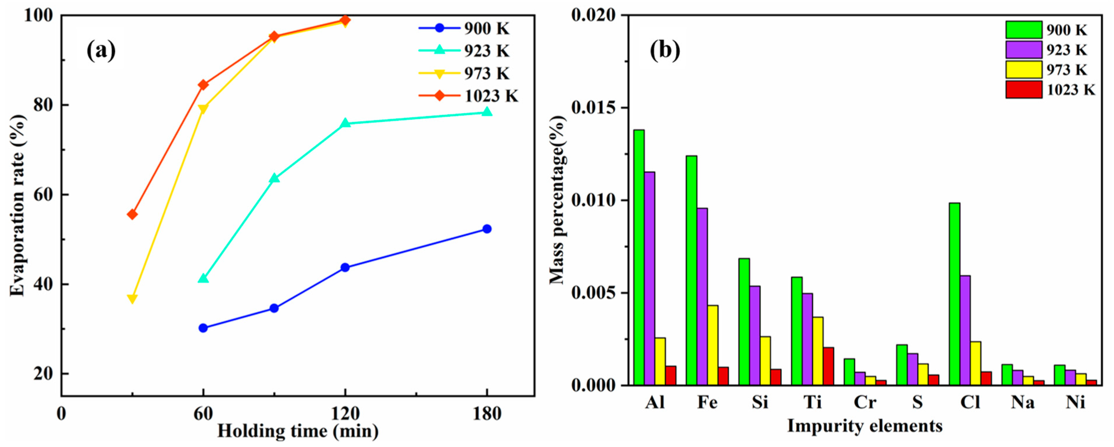
| Temperature/K | Al | Fe | Si | Ti | Cr | S | Cl | Na | Ni |
|---|---|---|---|---|---|---|---|---|---|
| 900 | 0.0138 | 0.0124 | 0.0069 | 0.0058 | 0.0014 | 0.0022 | 0.0098 | 0.0011 | 0.0011 |
| 923 | 0.0115 | 0.0096 | 0.0054 | 0.0049 | 0.0007 | 0.0018 | 0.0059 | 0.0008 | 0.0008 |
| 973 | 0.0026 | 0.0043 | 0.0026 | 0.0037 | 0.0005 | 0.0012 | 0.0024 | 0.0005 | 0.0006 |
| 1023 | 0.0011 | 0.0009 | 0.0009 | 0.0021 | 0.0003 | 0.0005 | 0.0007 | 0.0002 | 0.0003 |
Disclaimer/Publisher’s Note: The statements, opinions and data contained in all publications are solely those of the individual author(s) and contributor(s) and not of MDPI and/or the editor(s). MDPI and/or the editor(s) disclaim responsibility for any injury to people or property resulting from any ideas, methods, instructions or products referred to in the content. |
© 2023 by the authors. Licensee MDPI, Basel, Switzerland. This article is an open access article distributed under the terms and conditions of the Creative Commons Attribution (CC BY) license (https://creativecommons.org/licenses/by/4.0/).
Share and Cite
Ma, Z.; Ma, S.; Zhu, F.; Li, K.; Sheng, Z.; Li, Z.; Wang, Y. Preparation of High-Purity Magnesium from Electrolytically Produced Crude Magnesium via Vacuum Distillation. Metals 2023, 13, 811. https://doi.org/10.3390/met13040811
Ma Z, Ma S, Zhu F, Li K, Sheng Z, Li Z, Wang Y. Preparation of High-Purity Magnesium from Electrolytically Produced Crude Magnesium via Vacuum Distillation. Metals. 2023; 13(4):811. https://doi.org/10.3390/met13040811
Chicago/Turabian StyleMa, Zhanshan, Shangrun Ma, Fuxing Zhu, Kaihua Li, Zhuo Sheng, Zhanjun Li, and Yaowu Wang. 2023. "Preparation of High-Purity Magnesium from Electrolytically Produced Crude Magnesium via Vacuum Distillation" Metals 13, no. 4: 811. https://doi.org/10.3390/met13040811