Article

Improvement of Seizure Resistance in Ironing of Aluminum Alloy Sheets and Stainless Steel Cups by Utilizing Laser Textured Die Having Lubricant Pockets

1
Department of Mechanical Engineering, Toyohashi University of Technology, 1-1, Tempaku-cho, Toyohashi 441-8580, Japan
2
Department of Mechanical Engineering, Faculty of Engineering, King Mongkut’s University of Technology Thonburi, 126 Pracha-Uthit Rd., Bangmod, Thungkhru, Bangkok 10140, Thailand
3
Department of Industrial Engineering, Faculty of Engineering and Technology, Rajamangala University of Technology Isan, 744 Suranarai Rd., Mueang, Nakhon Ratchasima 30000, Thailand
*
Author to whom correspondence should be addressed.
Metals 2023, 13(4), 803; https://doi.org/10.3390/met13040803
Submission received: 15 March 2023 / Revised: 14 April 2023 / Accepted: 14 April 2023 / Published: 19 April 2023
(This article belongs to the Special Issue Laser Structuring for Development of Metallic Surfaces)

Abstract

:
Seizure during ironing negatively affects the quality of parts and die life. To prevent seizures, lubrication has to be improved. In this study, laser-textured dies with lubricant pockets were utilized to improve seizure resistance in the ironing of aluminum alloy sheets and stainless steel cups. The effects of array patterns of micro-pockets, such as grid and crossing array patterns with circular pockets, as well as a grooved array patterns on seizure resistance, were experimentally examined by strip ironing. The sheet and die materials were the A1050-O aluminum alloy and JIS SKD11 tool steel, respectively. Moreover, the underlying physics of the lubricant flow influencing the load-carrying capacity were investigated using three-dimensional computational fluid dynamics simulations. The optimum array patterns of the micro-pockets were then utilized on a tungsten carbide-cobalt (WC-Co) die surface for ironing SUS430 stainless steel cylindrical cups. The strip ironing results showed that the grid array pattern was successful in ironing sheets with a high ironing ratio. The grid array pattern increased the load-carrying capacity of the lubricant more than the crossing pattern, as demonstrated by the simulations, thereby improving the ironing limit. The subsequent ironing of stainless steel cups revealed that when using a textured die with a grid array pattern and lubricant without the extreme pressure additive in comparison to an untextured die, the ironing limit increased by 6% and the average ironing load decreased by 35%. The seizure resistance was improved because the pockets on the surface structured by laser surface texturing improved the load-carrying capacity during ironing.

1. Introduction

A reduction in the release of greenhouse gases, as with carbon dioxide being released from automobiles into the atmosphere, is essential for environmental protection. Consequently, the demand for electric vehicles (EV) that produce zero emissions is continuously increasing. However, battery-powered electric vehicles have a limited driving range. The amount of stored energy carried by EV is lower, owing to the limited space and weight of batteries. Thus, not only a high capacity, but also a reduction in the weight of the batteries and other parts is necessary to improve the energy efficiency of vehicles. Because aluminum alloys have high specific strengths and offer high potential for weight reduction, they are widely used to produce lightweight components in automobiles [1]. Thin-walled rectangular aluminum containers are widely used as battery cases. These cases are typically formed using multistage stamping processes, including deep drawing and ironing. Park et al. [2] utilized a numerical approach to design the process parameters and modify the initial blank shape in multistage deep drawing. Rectangular drawn cups with extreme aspect ratios were successfully obtained, and the amount of waste material was reduced by improving the initial blank shape. Backward extrusion processes are also considered in the manufacture of battery cases. In this process, lubrication has a significant effect on the magnitude of the earing and forming loads. The earing and forming loads increased with the friction factor [3]. Inoue and Yamaguchi [4] investigated the effect of plastic anisotropy on the ironing formability of aluminum alloy sheets, and discovered that less anisotropy resulted in less fracture during ironing. Ironing was also used in the flanging process. Cui et al. [5] investigated the effects of ironing on flanging characteristics during the Lorentz-force-driven hole flanging process, and proposed a flange height prediction formula that was shown to be feasible when compared to experimental heights. Aluminum alloys and stainless steel develop a thin, hard adherent film of oxide on their surface that protects the metal from corrosion. They are prone to being picked up on the forming tool when the oxide film is cracked by local plastic deformation caused by high normal and shear stresses in deep drawing and ironing. Thus, the generated metallic contact determines the local micro-welding. Due to the progressive relative movement between the sheet and die, the bonding is torn apart. Separation occurs inside the volume of the sheet material and consequently initiates the seizure. Therefore, a lubricant is conventionally used to prevent the adhesion of the sheet material to the forming tools. The seizure can be lowered by applying a lubricant or utilizing a textured die surface [6].
Surface texturing has been widely implemented to improve the tribological characteristics of friction pairs such as journal bearings, thrust bearings, and mechanical seals [7,8,9]. Surface texturing has also become an attractive approach for improving the tribological performance in metal forming processes because textured surfaces are able to assist with lubrication by retaining and feeding lubricants as well as trapping wear debris [6]. Initial studies have emphasized the texturing of the work surface with a deterministic–stochastic structure produced by transferring an electron-beam-textured roll surface. The stochastic structure, consisting of random lubricant pockets, could not detain the lubricant, whereas the deterministic sheet-surface structure with isolated lubricant pockets was able to transport the lubricant directly into the deformation zone by building up hydrostatic lubricant pressure [10]. The entrapment and escape of the liquid lubricant during metal forming was observed. The trapped lubricants escaping from the pockets during strip drawing influence the drawing load [11]. However, textured sheets do not function when the surface is completely flattened by a large deformation, and for liquid lubricants, the high contact pressure occurring between the forming tools and workpiece interface during forming may lead to the breakdown of the lubricant film and seizure. Because tools or dies only undergo elastic deformation, the texturing of die surfaces facilitates forming, even for long-term use. Costa and Hutchings [12] examined the effects of lubricant pocket patterns textured by photochemical etching on lubrication in the drawing of stainless steel strips. The friction force was considerably reduced with grooves oriented perpendicular to the drawing direction, probably because of the presence of lubricant pockets encouraging micro-plasto-hydrodynamic lubrication. Aramaki et al. [13] combined shot-peening for improving the seizure resistance and nitriding for enhancing the anti-abrasion, and found that the seizure resistance in the drawing test of high-strength steel sheets was improved with the die subjected to a double-shot treatment and nitriding because of the micro-pockets enhancing the lubricating effect. In addition, the combination of shot treatment and nitriding, as well as applying oil mixed with a solid lubricant, improved the die life in the drawing test of high-strength steel sheets [14]. The seizure resistance of tool surfaces prepared by turning, grinding, polishing, shot-peening, and laser surface texturing was investigated. Polishing to remove sharp peaks on the bearing surface, giving a plateau-like topography, improved the seizure resistance of the forming tool [15]. The seizure resistance in the ironing of stainless steel cups was improved by using a TiCN-based cermet die with fine lubricant pockets textured by shot-peening followed by polishing. The friction was reduced by squeezing the liquid lubricant from the pockets into the die-cup interface during ironing [16]. Although various texturing techniques can be used to improve tribological performance, including electron beam texturing, etching, shot-peening, and machining, laser surface texturing is a commercially available technique that is widely used in industry. It has a short processing time, excellent control over the shape and size of micro-pockets, and the ability to ablate most materials [17]. Geiger et al. [18] introduced texturing using excimer laser radiation to the surface of a TiN-coated punch for cold forging. The textured surface dominated by micro-pockets had the ability to store and provide lubricants during the forming process, thereby reducing friction and consequently reducing the tool load. Thus, the tool life was increased by the micro-pockets. Wakuda et al. [19] employed excimer laser beam machining and abrasive jet machining for the texturing of micro-pockets on a silicon nitride ceramic surface, and found that an appropriate size and density of pockets could lead to a substantial reduction in friction. The pocket geometry, however, had little effect on the reduction in friction coefficient regardless of rounded or angular profiles. Schneider et al. [20] discovered that the pocket pattern, density, and aspect ratio, which is a depth to diameter ratio, influence friction reduction. The pockets in a hexagonal pattern with a pocket density of 10% and an aspect ratio of 0.1 provide the greatest reduction in friction. Daodon and Saetang [21] improved the frictional property of a cold work steel tool in sliding against an advanced high strength steel by using the laser texturing process, and found that the friction coefficient was low, with a pocket density of 5.6%, whereas the wettability of textured surfaces was insignificantly changed compared to that of the untextured one. Vilhena et al. [22] employed laser surface texturing to hardened bearing steel, and the parameters of the laser surface texturing process were optimized. Well defined micro-pockets improved the tribological behavior. Meng et al. [23] demonstrated that friction can be reduced by using the laser textured tool having micro rectangle pockets with a flat bottom. Shimizu et al. [24] have clarified the underlying mechanism and relationship between the geometrical parameters of dimple surface textures and lubrication properties during the ironing process of the stainless steel sheet by an in situ observation system using transparent silica glass dies and a high speed recording camera. The influence of the lubricant reservoir effect on the load carrying capacity of the lubricant during the ironing operation depends on the pocket size. The lowest punch force was obtained for the pocket diameter of 50 µm, and a high viscosity lubricant seemed to be successfully transferred between the pockets, enhancing lubrication. Furthermore, laser texturing was used to texture a Ti6Al4V titanium alloy with various surface morphologies, such as lines, crosshatching, and dimples. Dimples have the lowest steady-state coefficient of friction [25]. The effect of Ti6Al4V textured surface dimple densities on friction and wear was investigated, and it was discovered that the surfaces with the highest dimple densities had lower friction and wear [26].
The general knowledge for the purpose of surface texturing is the generation of load-carrying capacity induced by the hydrodynamic pressure [8,27,28]. Theoretical studies have focused on investigating the underlying lubrication mechanism of micro-pockets. Extensive numerical investigations have been performed to assess the tribological behaviors and characteristics of micro-dimple textured surfaces under hydrodynamic lubrication [29,30]. The Reynolds equation was first introduced to investigate the characteristics of hydrodynamic lubrication in the presence of textured surfaces. The pressure distribution in thin-film lubrication (TFL) was obtained. However, the TFL model derived from the Reynolds equation is not accurate at high Reynolds numbers, where inertial effects become significant [31,32,33]. Recently, with advancements in numerical simulations, the Navier-Stokes (N-S) equations and governing equations of fluid flow have been adopted. The characteristics and behaviors of lubricant flows with textured surfaces can be thoroughly evaluated via computational fluid dynamics (CFD) simulations based on the N-S equations.
In this work, laser-textured dies with lubrication pockets have been utilized for the ironing of aluminum alloy sheets and stainless steel cups. Different array patterns of a micro-pocket-textured die surface were employed. The objectives of the present study are to examine the effect of array patterns of micro-pocket-textured dies on the improvement of seizure resistance, and to investigate the underlying physics of lubricant flow in the strip ironing process of aluminum alloy sheets with different array patterns of micro-pocket-textured die surfaces using three-dimensional computational fluid dynamics simulations. The tribological characteristics of the grid and crossing array patterns of a micro-pocket-textured die surface were compared. In addition, the optimum lubricant pocket was further applied to the ironing of cylindrical stainless steel cups.

2. Experimental Procedures

2.1. Tool and Workpiece Materials

The strip ironing dies were JIS SKD11 cold work tool steel hardened to a hardness of 791 HV and finished by grinding, followed by polishing to a smooth surface prior to the laser texturing process. The surface roughness was measured using a surface roughness measuring instrument (SJ-210 series, Mitutoyo Corp., Kanagawa, Japan) with a 2D stylus method using an 8 mm measured length with a 0.8 mm cut-off and a magnification of 10,000. The hardness of the strip and cup materials was measured using a microhardness tester (HMV, SHIMADZU Corp., Kyoto, Japan). The arithmetic average roughness Ra of the strip ironing dies was 0.01 µm. The strip material was an A1050-O aluminum alloy with a thickness of 0.59 mm and width of 15 mm. The arithmetic average roughness in the ironing direction, Ra, and hardness of the sheets were 0.12 µm and 23 HV, respectively. For cylindrical cup ironing, the die was made of tungsten carbide-cobalt (WC-Co), with a hardness of 1600 HV and an arithmetic average roughness in the ironing direction, Ra = 0.004 µm. The cylindrical cups were made of ferritic stainless steel SUS430 with an average sidewall thickness of 0.59 mm. The arithmetic average roughness in the ironing direction, Ra, and the hardness of the cup were 0.42 µm and 167 HV, respectively. The reported surface roughness and hardness values were the averages of at least three measurements.

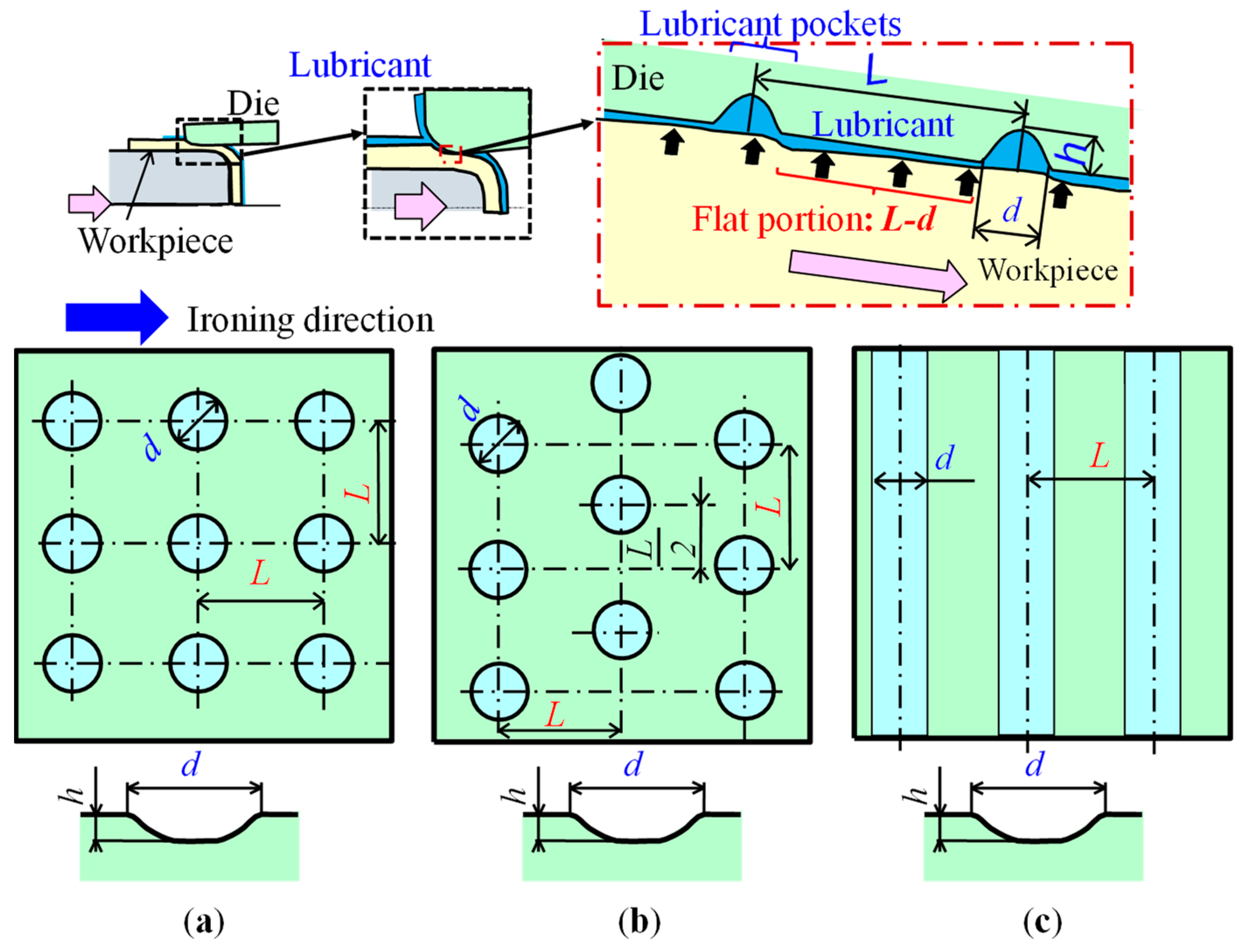
2.2. Laser Surface Texturing

The texturing process for fabricating micro-lubricant pockets was carried out using an ultra-short pulse laser, which is a laser machining process involving a laser beam as a heat source. It is a thermal process employed to remove materials without mechanical engagement, where the work material is heated to the melting or boiling point and removed by melt ejection, vaporization, or ablation mechanisms [34]. A schematic illustration of the array patterns of micro-lubricant pockets is shown in Figure 1. The designs of the array patterns of the micro-pockets were selected based on the results of the optimum shape of the pockets for ironing obtained by Nawa et al. [35] and Kobayashi et al. [36]. First, the effect of the geometrical parameters of the micro-pockets on the improvement of seizure resistance was evaluated by the strip ironing of the aluminum alloy sheets. Three types of patterns, namely grid and crossing array patterns with circular pockets, as well as a grooved array pattern, were fabricated on planar cold work tool steel dies.
The geometrical parameters of the array patterns of the micro-pockets are summarized in Table 1. Circular pockets were arranged in a grid array pattern with diameters d of 15 and 30 µm and depths h of 1, 2, 3, 4, and 6 µm, while the distances between pockets L were 33, 50, and 100 µm, respectively. For the crossing and grooved array patterns, the pocket diameter and groove width d were 15 and 30 µm. The depths h were 2 and 4 µm. The distance between the circular pockets and between grooves L was 50 µm. Textured surfaces were observed using a 3D laser confocal microscope (VK-9500 GII, Keyence Corp., Osaka, Japan). Figure 2 shows micrographs and 2D profiles of the array patterns of the micro-lubricant pockets. The micro-pockets were arrayed on a flat-smooth surface, and rough recast bumps at the edges of the pockets were not observed in the physical observations. This offers a positive effect of textured surfaces on lubrication [37]. The optimum geometrical parameters of the micro-lubricant pocket were further utilized for texturing the die for ironing stainless steel cylindrical cups.

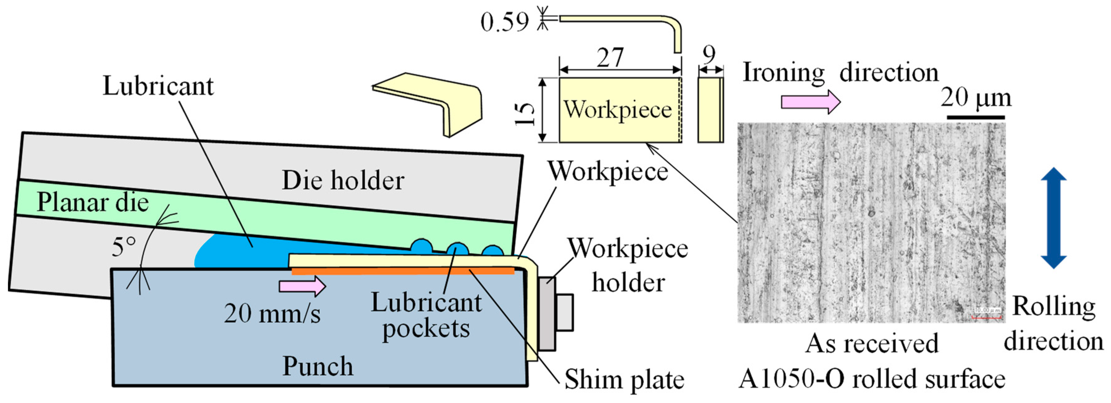
2.3. Strip Ironing of Aluminum Alloy Sheets

Strip ironing was conducted to evaluate the performance of the geometrical parameters of the micro-pockets on seizure resistance. Figure 3 shows a schematic of the strip ironing. Planar dies with different array patterns of lubricant pockets were used to iron flat A1050-O aluminum strips. The ironing was performed along the transverse rolling direction of the sheet, although the rolled surface of the aluminum sheets has a manufacturing texture oriented along the rolling direction. The effect of sheet surface texture orientation on seizure resistance was not considered because the sheet textures did not function when the surface was completely flattened by a large deformation [6]. The lubricant, paraffinic mineral oil without an extreme pressure additive (ISO VG500) with a kinematic viscosity of 433 mm2/s at 40 °C was applied to the die-workpiece interface. The ironing speed was set at 20 mm/s. A load cell (UBFH-2kN, Unipulse Corp., Tokyo, Japan) was installed between the punch and rod of a press to capture an ironing load signal. The signal was amplified using a strain amplifier (GL7-DCB, Graphtec Corp., Yokohama, Japan) and recorded using a data logger (GL7000, Graphtec Corp., Yokohama, Japan) at a sampling rate of 1 kHz. The ironing ratio r is determined by the difference between the initial and ironed sheet thickness divided by the initial sheet thickness as expressed by Equation (1). The ironing ratio was changed to accelerate the occurrence of seizure. To change the ironing ratio, the clearance between the die and punch was altered by changing the thickness of the shim plate located between the punch and workpiece. Each ironing condition was repeated three times. After ironing, the adhesion of work material on the die and the seizure on the workpiece surface occurring at certain ironing ratios were observed by an optical microscope. Seizure resistance, also known as the ironing limit, is defined at a maximum ironing ratio that has no occurrence of seizure.
r = t 1 t 2 t 1 × 100 %
where r is the ironing ratio, t1 is the initial sheet thickness, and t2 is the ironed sheet thickness.

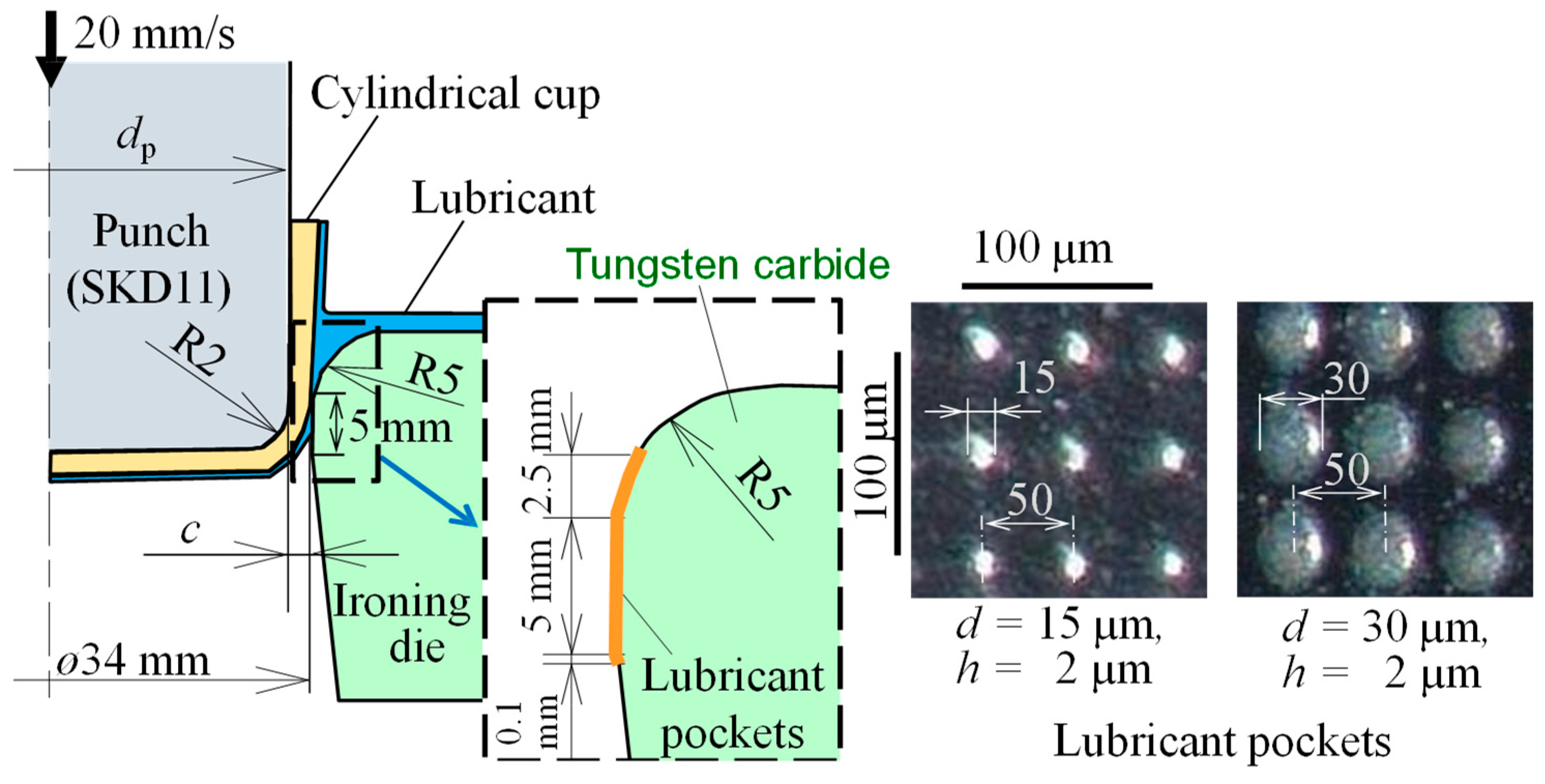
2.4. Ironing of Stainless Steel Cups

Ironing imitates the industrial operating conditions where the die surface encounters large normal loads. The optimum geometrical parameters of the array patterns of micro-pockets with high ironing limits were selected for texturing the WC-Co die surface, and their seizure resistance performance in the ironing of SUS430 stainless steel cylindrical cups was evaluated and compared with those of a smooth surface die. The ironing conditions for stainless steel cups and die surfaces are shown in Figure 4. The grid array patterns with the diameters d of 15 and 30 µm and a depth h of 2 µm were fabricated on the WC-Co die surface and the arithmetic average roughness, Ra of the smooth flat area between pockets was 0.004 µm. Two types of lubricants, paraffinic mineral oil without an extreme pressure additive (ISO VG500) with a kinematic viscosity of 433 mm2/s at 40 °C, and a commercial-grade liquid lubricant of highly refined mineral oil with a chlorinated extreme pressure additive and a kinematic viscosity of 513 mm2/s at 40 °C (G-751 M, Nihon Kohsakuyu Co., Ltd., Tokyo, Japan) were applied. Prior to ironing, cylindrical cups of various sizes were produced from SUS430 ferritic stainless steel circular blanks with a diameter of 66 mm and a thickness of 0.59 mm. The surface of the stainless steel sheet has a manufacturing texture oriented along the rolling direction. The sheet texture was deformed by deep drawing while preparing cylindrical cups. The effect of the sheet surface texture orientation on seizure resistance was not taken into account. Before being ironed, a drawn cup was tied to the punch and forced through the die at an ironing speed of 20 mm/s. A load cell (HCS-100kN, Showa Measuring Instruments Co., Ltd., Tokyo, Japan) was installed between the punch and a slide of a press machine to capture an ironing load signal. The signal was amplified by a strain amplifier (DPM-95, Kyowa Electronic Instruments Co., Ltd., Tokyo, Japan) and was recorded with a data logger (GL980, Graphtec Corp., Yokohama, Japan) at a sampling rate of 1 kHz. To increase the ironing ratio, the drawn cup diameter and punch diameter were raised, while the inner die diameter was kept constant at 34 mm. The ironing ratio r was determined by a difference between the initial thickness of the blank and the average wall thickness of the ironed cup divided by the initial thickness. Severe deformation of the cup occurs as the ironing ratio rises. When the ironing ratio goes above a particular level, the die will be adhered by the work material or the cup will be seized up. The ironing limit is the highest ironing ratio that is free of flaws such as seizure on the die or cup. The higher ironing limit results from the higher seizure resistance.

2.5. Numerical Simulation of Lubricant Flow Behavior

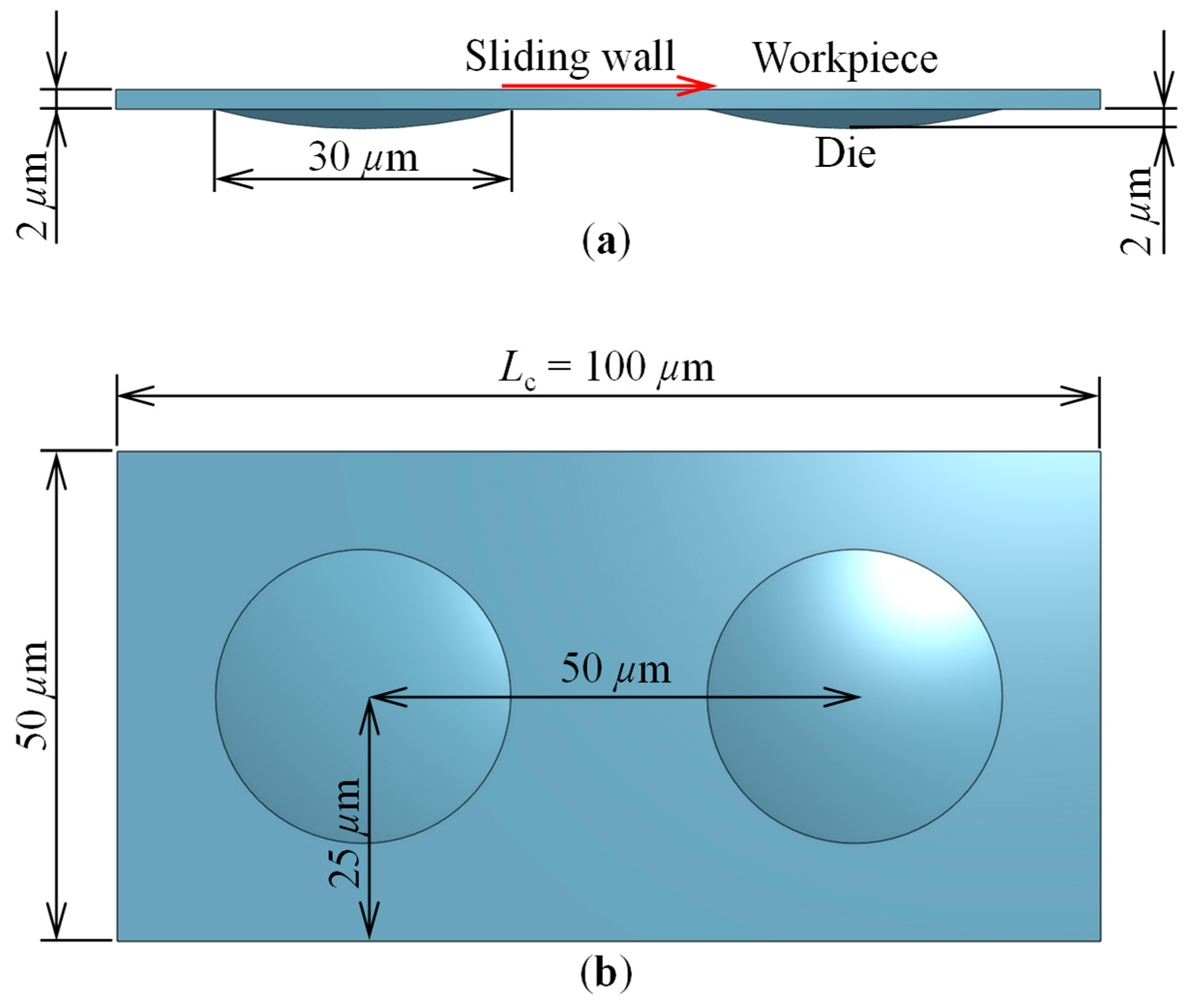
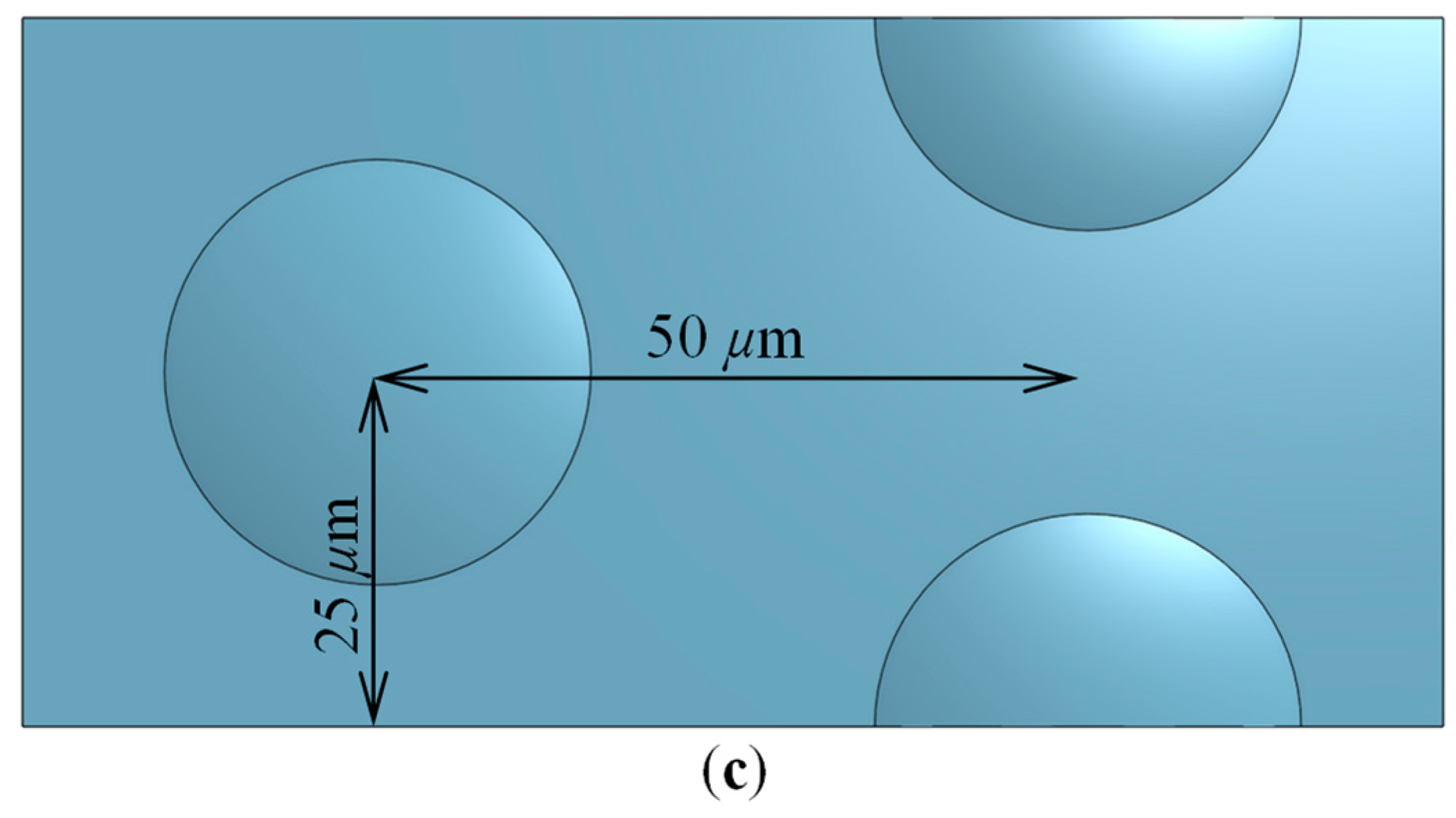
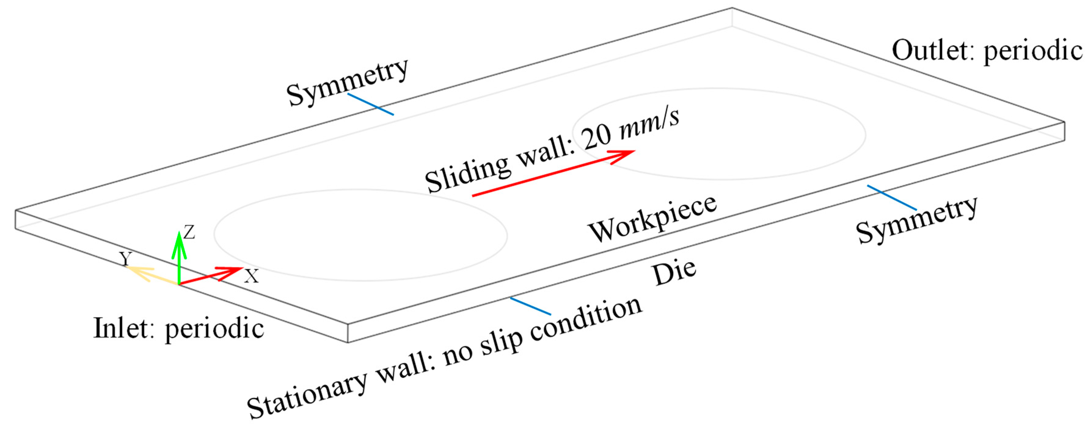
2.5.1. Physical Model

The computational fluid dynamics (CFD) analysis was performed by using ANSYS Fluent 19.2 software. The underlying physics of the lubricant’s flow behavior in circular pockets with optimal geometrical parameters arranged in grid and crossing array patterns as discovered by strip ironing findings was analyzed. The tribological components can be roughly simplified as a two parallel contacting couple between the die and the workpiece with thin-film lubrication. The geometrical model of the simplified contacting couple and the computational fluid domain with micro-lubricant pockets are presented in Figure 5. The width and the length of the domain are 50 µm and 100 µm, respectively. The gap between the die and the workpiece is 2 µm. The depth and the diameter of a micro-pocket unit are 2 µm and 30 µm, respectively. The distance between pockets is 50 µm. For the grid array pattern, there are two micro-pocket units along the centerline of the plate (Figure 5b). For the crossing array pattern, there is one micro-pocket unit along the centerline of the die plate, and two halves of a micro-pocket unit are located at the side edges of the die plate (Figure 5c).

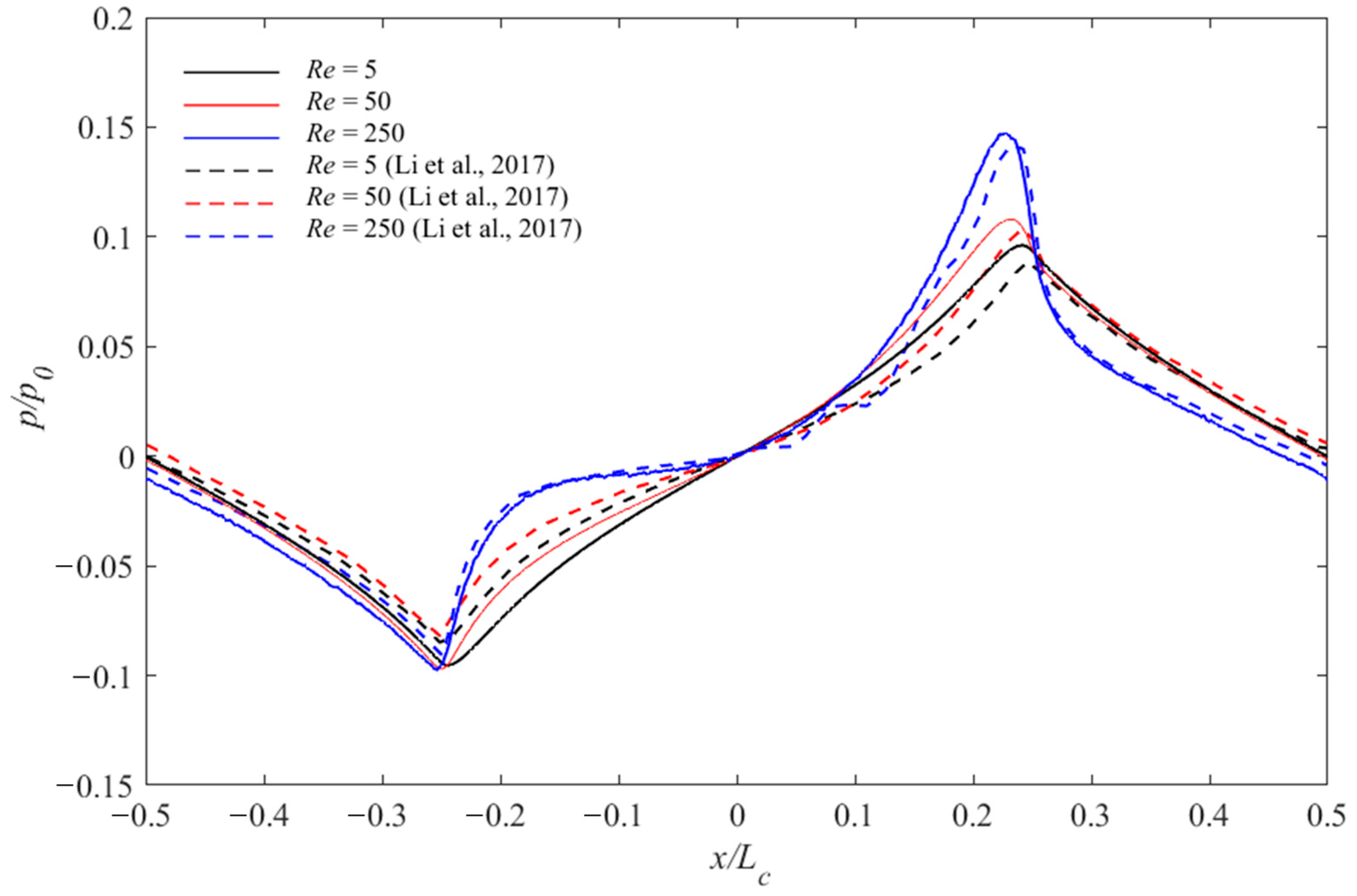
2.5.2. Validation of CFD Simulations

It is crucial to ensure that the CFD simulations provide reliable results. Thus, lubricant flow between a two parallel contacting couple is modelled using only a single micro-pocket unit. Parameters, geometries, and boundary conditions are adopted from Li et al. [38]. The pressure distribution on the middle plane of the micro-pocket unit is investigated at Reynolds numbers equal to 5, 50, and 250, respectively. Figure 6 shows that the results agree well with those of Li et al. [38]. The pressure decreases upstream, rises significantly over the front part of the micro-pocket unit, reaches the maximum value at the rear part, and then decreases to zero downstream. It is obvious that as the Reynolds number increases, the pressure distribution becomes closer to those of Li et al. [38].

2.5.3. Methodology

  • Governing Equations
The incompressible Navier-Stokes equations are adopted to describe the behavior of the lubricant flow in the strip ironing process. The effects of convective inertia in lift generating mechanisms due to the presence of a micro-pocket textured surface are included. It is noted that the body force term is negligible and the isothermal condition is assumed. Thus, the simplified Navier-Stokes equations are as follows:
ρ u · u = p + · μ u
and
· u = 0
where ρ is the density of the lubricant, u is the velocity vector, p is the static pressure, and μ is the dynamic viscosity, respectively. It is noted that all simulations are performed in ANSYS Fluent, a commercial computational fluid dynamics software.
  • Boundary conditions and parameter setting
The boundary conditions and parameters are defined as shown in Figure 7. A periodic boundary condition is applied at the inlet and the outlet. A symmetrical boundary condition is imposed at side edges. A no-slip boundary condition is assigned on the die and the workpiece. The speed of the workpiece is set at 20 mm/s, while the die plate is stationary. The x, y, z define the streamwise, spanwise, and wall-normal directions, respectively.
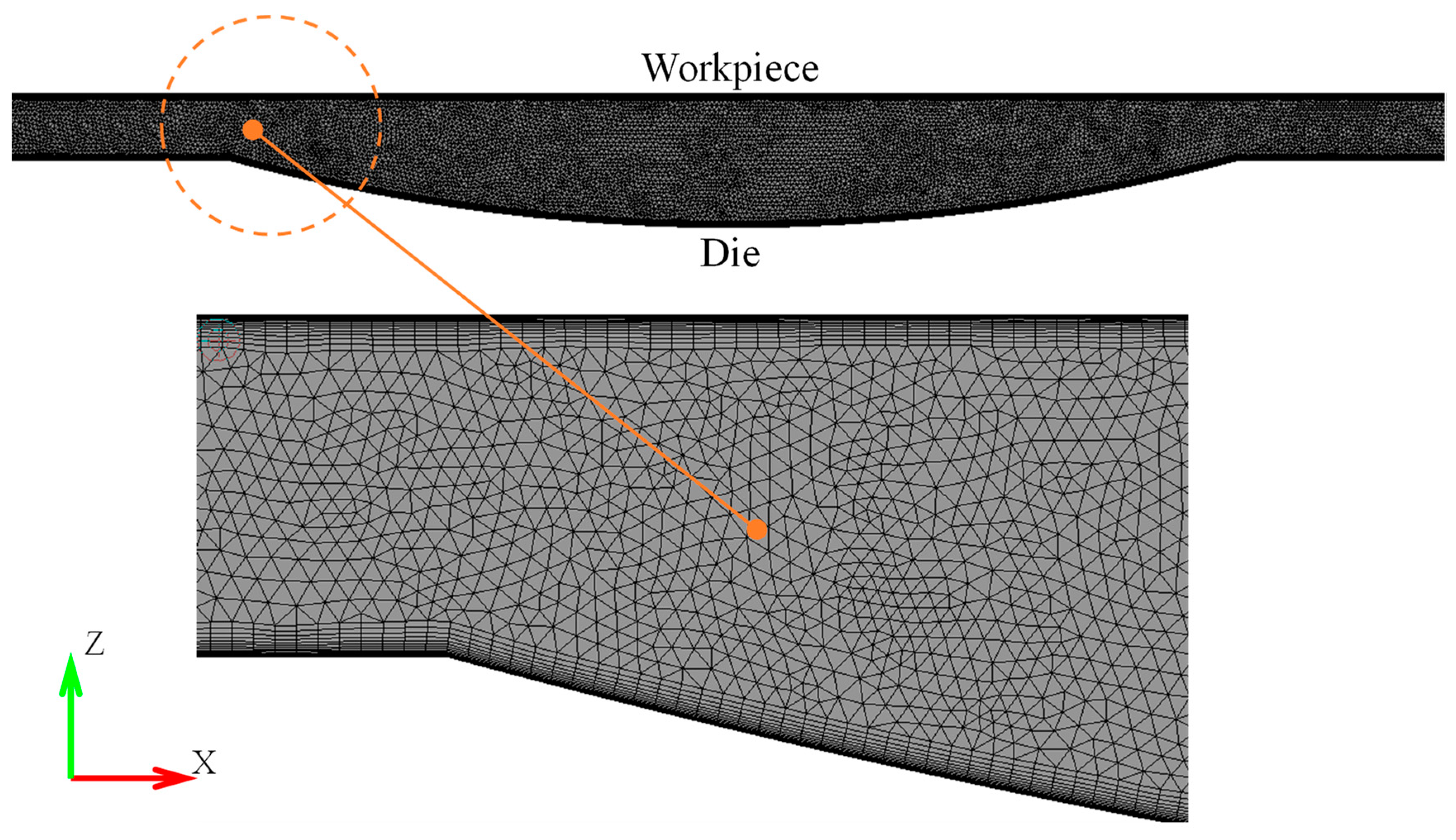
  • Mesh generation/Mesh size
Meshes are generated based on the three-dimensional model of a two parallel contacting couple between the die and the workpiece with thin-film lubrication, as shown in Figure 8. A mesh type tetrahedral is employed in the region far away from the die and workpiece surfaces, while the triangular prism mesh type is utilized in the inflation layers. Both mesh types, based on triangular surfaces, are appropriate for the domain containing curved surfaces. The average skewness and orthogonal quality are 0.176 and 0.823, respectively. Fifteen inflation layers are used near surfaces to capture the flow behavior in the boundary layer.
In order to ensure the accuracy of the simulations, the mesh independence analysis was performed as shown in Table 2. Mesh elements were gradually increased from 366,051 to 14,293,507. This resulted in the reduction of the average mesh size from 1.0 μm to 0.18 μm. It showed that the value of F d * remained rather constant, while the value of F z * significantly varied with the mesh size. The variation of the mesh elements from 7,152,816 to 14,293,507 caused the change in the value of F z * to be less than 0.1%. Thus, it is suggested that the simulation with mesh elements greater than 14,293,507 gives the result that is independent of the mesh resolution. Therefore, the 14,293,507 mesh element case was used for further simulations.
  • Lubricant properties
The properties of the ISO VG500 lubricant and analytical conditions for laminar one-phase flow analysis are presented in Table 3. The sliding speed and flow velocity were equal due to the no-slip condition. The lubricant film thickness was equal to 2 µm. The atmosphere temperature was 293.15 K. The contact angle of the dropped lubricant on the polished die was approximately 20°.

2.5.4. The Tribological Characteristics and Behaviors

Characteristics and behaviors of lubricant flows with the presence of a micro-pocket textured surface can be assessed by the following quantities: (1) non-dimensional load-carrying force F z * ; (2) non-dimensional shear force F d * ; (3) friction coefficient f. The load-carrying force is computed by considering the pressure acting on the workpiece. It can be obtained by the following equation:
F z = p x , y d x d y
where F z is the load-carrying force derived from the integration of pressure distributed over the entire workpiece. The non-dimensional load-carrying force F z * can then be achieved by normalizing F z with the characteristic pressure p0 and the surface area of the workpiece Sw as follows:
F z * = F z p 0 S w
or
F z * = F z p 0 S w = F z h t 2 μ u 0 L c S w
where
p 0 = μ u 0 L c h t 2
It is noted that u0 is the characteristic velocity of the lubricant. In the present study, u0 is the flow velocity υf presented in Table 3. Lc is the length of the computational domain in the x- direction. ht is the thickness of the lubricant film. Clearly, the higher the non-dimensional load-carrying force F z * , the greater the load-carrying capacity of the friction pair. Similar to the load-carrying force, the shear force is obtained by considering the shear stress acting on the workpiece as follows:
F d = τ x , y d x d y
where F d is the shear force derived from the integration of shear stress distributed over the entire workpiece. The non-dimensional shear force F d * can then be achieved by normalizing F d with the characteristic pressure p0 and the surface area of the workpiece Sw as follows:
F d * = F d p 0 S w
or
F d * = F d p 0 S w = F d h t 2 μ u 0 L c S w
It represents the average shear force acting on the workpiece. Thus, the friction coefficient f can be derived from the ratio between the non-dimensional shear force F d * and the non-dimensional load-carrying force F z * as follows:
f = F d * F Z *
The friction coefficient f indicates the tribological performance of the thin-film lubrication. The lower the friction coefficient, the greater the tribological performance.
It was noted that the texture density, the ratio of the micro-pocket area to the overall surface area, was equal to 28.27%. The aspect ratio, the ratio of the micro-pocket depth to the micro-diameter diameter, was 0.067. The Reynolds number in the present study is defined as
R e = ρ u 0 h t μ
which is based on the lubricant film thickness ht.

3. Results and Discussion

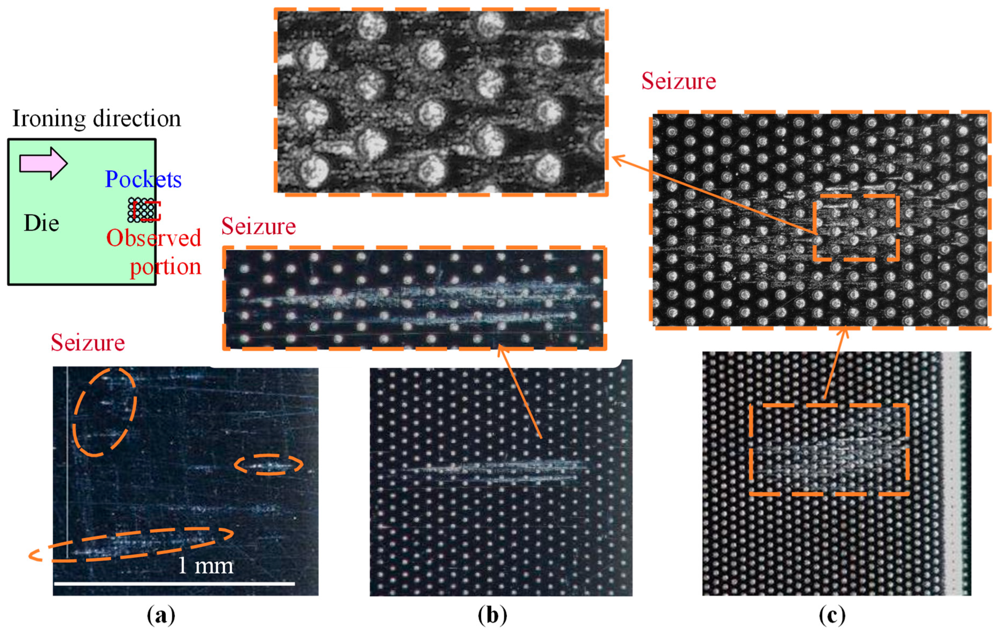
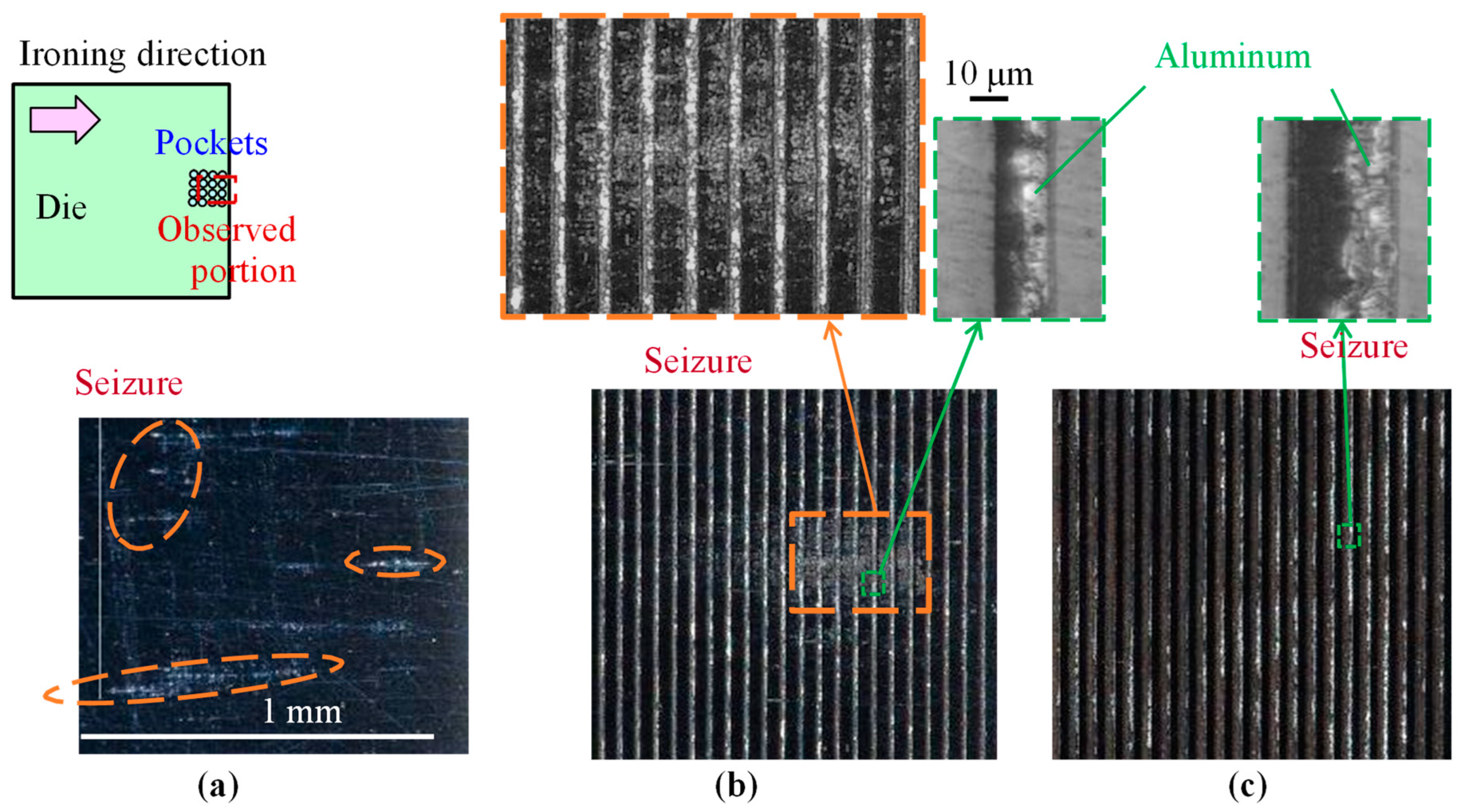
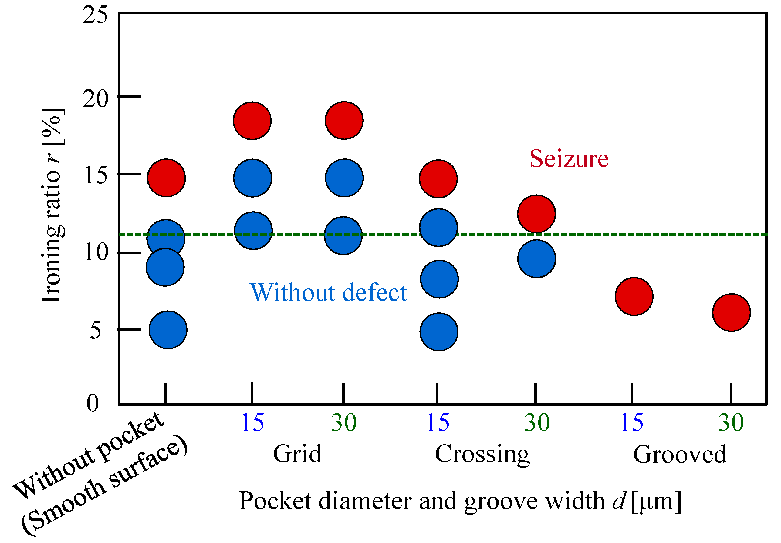
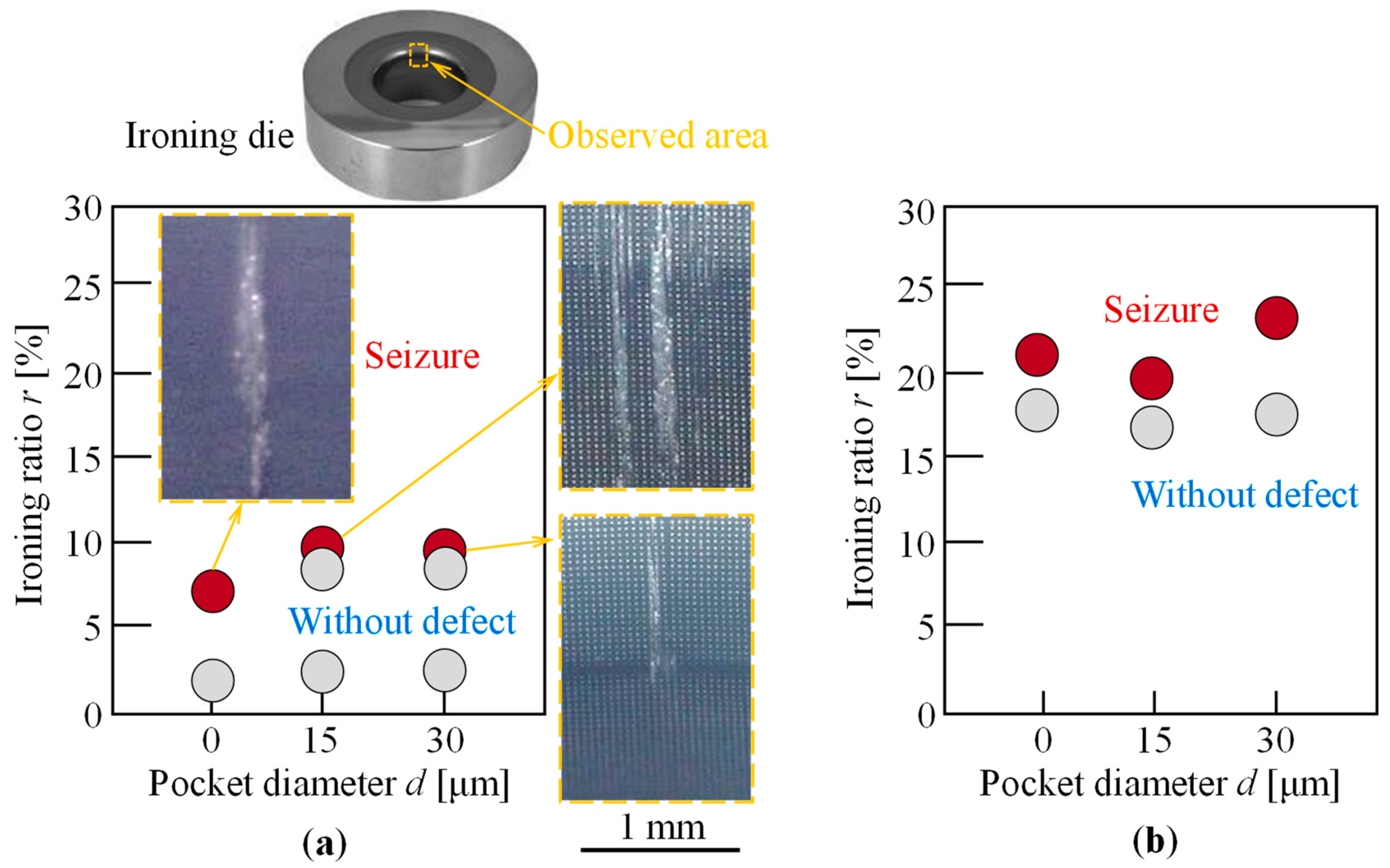
3.1. Strip Ironing of Aluminum Alloy Sheets

The ironing limit is evaluated by observing the occurrence of seizure at the die and workpiece surfaces after ironing, as shown in the optical micrographs in Figure 9. The increasing of the ironing ratio leads to the elevation of the contact pressure between the die and workpiece surfaces inducing the seizure. At certain ironing ratios, the seizure was observed. Even though there was no seizure on the die at r = 15% (Figure 9a), seizure appeared on the smooth area between pockets on the die and on the workpiece surface at r = 18% (Figure 9b,d). The ironing limit of this test is therefore equal to 15% because it is defined as the level of the maximum ironing ratio prior to the occurrence of seizure.
The grid-array patterned circular pockets were used to investigate the effect of pocket depth on the occurrence of seizure. Both the pocket diameter and the distance between pockets were maintained at d = 30 µm and L = 50 µm, respectively, as shown in Figure 10. In comparison with the smooth surface die at the same ironing ratio of 15%, only the pocket depth of 2 µm prevented seizure, but the workpiece material adhered and seized for the shallow pocket depth of 1 µm, and the deeper pocket depth resulted in early seizure at the low ironing ratio.
The effect of pocket depth at a distance between pocket L of 50 µm on the ironing limit with a grid array pattern is illustrated in Figure 11a. When the pocket depth is too shallow (1 µm) or excessively deep (4 and 6 µm), the lubricant has no effect on improvement of seizure resistance. The pocket depth is one of the geometrical parameters of micro-pockets that affect seizure resistance. The proper pocket depth is able to minimize the coefficient of friction [39]. The highest ironing limit seems to be best with a pocket depth of 2 µm. According to Scaraggi et al. [40], an optimal depth of micro-pocket minimizes friction by increasing the load-carrying capacity of lubrication with generating cavitation. However, micro cavitation disappears as the pocket depth increases, leading to an increase in the friction coefficient again.
Figure 11b shows how the length of the flat portion between pockets on the die surface affects the ironing limit. When the length of flat portion Ld is too long (70 µm), the ironing limit becomes the same as the smooth one without a pocket. Directly observing the contact interface during ironing, Shimizu et al. [24] discovered that there was less lubricant transfer and that the lubricant did not reach the adjacent pocket for a longer length of the flat portion. The grid array pattern only works when the flat portion is between 20 and 35 µm long. At a shorter flat portion length of 18 µm, the ironing limit turns lower than the smooth surface die. The real contact area of the die-workpiece interface is reduced by the flat portion’s shorter length or higher pocket density. According to the analysis of the contacting conditions by Wang et al. [41], which included contact stress and deformation, a smaller contact area results in higher contact pressure and a higher stress concentration of asperity causes more elastic deformation, which ultimately results in a higher friction coefficient.
Ironing load-stroke curves and an average ironing load with an ironing ratio of 10% is shown in Figure 12. Although the maximum ironing loads with and without the lubricant pockets are similar at a stroke of about 5 mm, the ironing loads with the lubricant pockets are smaller than that of the ironing load without the lubricant pockets. The average ironing load shows the maximum decreasing by 20% with the pocket diameter of d = 15 µm.
The occurrence of the seizure on the die crossing array pattern, pocket diameter d of 15 µm at r = 15%, and d of 30 µm at r = 12% is shown in Figure 13. In d = 15 µm of the array pattern, the seizure continuously appears in the ironing direction on the flat portion between pockets in the die surface. Although the seizure area is lager in d = 30 µm of the array pattern with the smaller ironing ratio, the seizure does not appear on the flat surface of the pocket outlet side. Both ironing limits for the die crossing array pattern are the same or less than the limit for the smooth surface die.
The occurrence of the seizure on the die with smooth surface and with the grooved array pattern is shown in Figure 14. The seizure occurs in not only the flat die surface, but also the pocket groove in both the grooved array patterns in the smaller ironing ratio. This is because the lubricant does not extend to the flat die surface portion, i.e., the lubricant flows down to the groove.
Figure 15 depicts the ironing limit with various array patterns at h = 2 µm and L = 50 µm. The ironing limit is 4% higher with the grid array pattern than it is with the smooth surface without a pocket. It is believed that under these circumstances, an adequate supply of lubricating oil is delivered into the interface, reducing friction. Thus, the ironing limit rises while the ironing load falls (Figure 12). The ironing limit of the crossing array pattern is less than or equal to the smooth surface without the pocket because the flat portion between pockets Ld in the ironing direction is excessively long, making it difficult for the lubricant to reach between the adjacent pockets, lowering the lubricating effect. The beneficial impacts of the grid array pattern are further supported by the CFD findings, which are displayed in Table 4, and show that the grid array pattern improves the load carrying capacity F z * more than the crossing one.
For the grooved array pattern, it can be observed that the seizure was caused by the occurrence of direct contact between the die-workpiece interface (Figure 14b,c). When compared to a smooth surface without the pocket, the ironing limit is reduced. The grooved array pattern has the lowest ironing limit among the three array patterns with early seizure because it has a smaller real contact area than the other array patterns, which may lead to a stronger asperity contact pressure and, subsequently, direct contact. Another explanation is that the grooved array pattern has a high area density, which causes the lubricant to flow down and remain in the groove rather than being fed to the interface, resulting in inadequate lubricant transfer. An experimental investigation on the frictional behavior of micro-grooved patterns textured on journal bearing surfaces conducted by Adatepe et al. [42] demonstrated that the micro-grooved patterns had a higher friction coefficient than the smooth one.
Although the effect of temperature generated by different array patterns of micro-pockets on seizure resistance was not taken into account, the temperature of the workpieces may locally increase during the ironing operations. Seizure, according to Groche and Nitzsche [43], is most preferably initiated in areas of microscopic stress concentrations with the greatest mechanical and thermal stresses. The grid array pattern that enhances the lubricating effect and improves the load-carrying capacity may lower the mechanical and thermal stress concentrations at the asperity contact, resulting in higher seizure resistance.

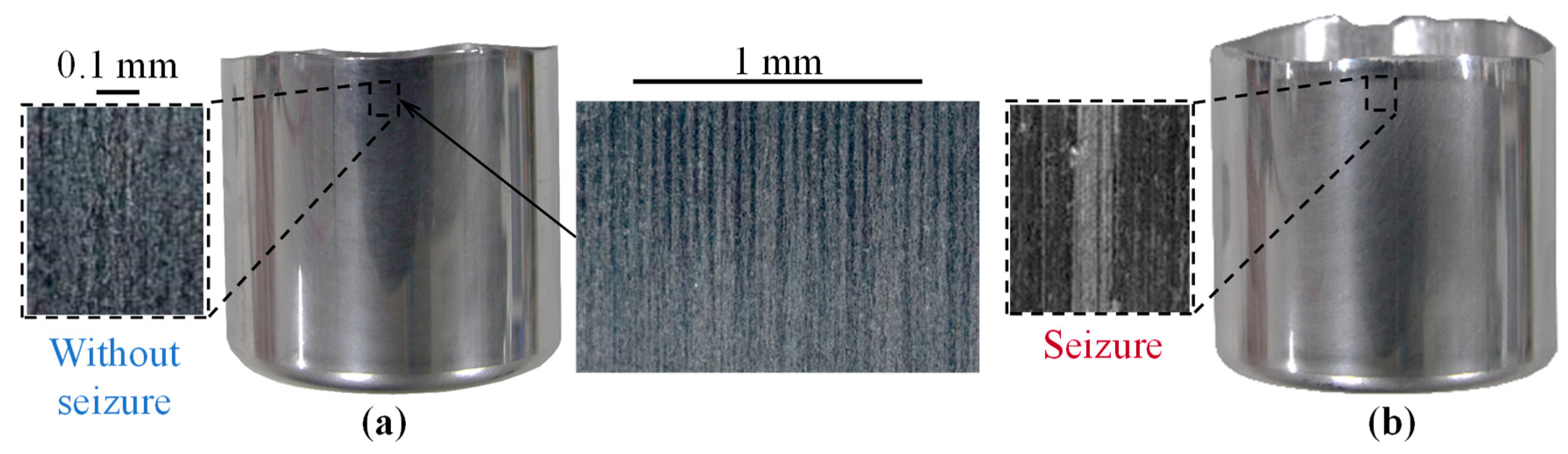
3.2. Ironing of Stainless Steel Cups

The ironing limit used to assess seizure resistance is the highest ironing ratio free of a flaw, such as an observed seizure on the die or cup surface after cylindrical cup ironing. As employing the textured die with the proper geometrical parameters of circular pockets arranged in the grid array pattern could increase the ironing limit, as illustrated in Figure 15, the optimum array pattern was subsequently textured on the WC-Co die used to iron stainless steel cups. The stainless steel cup obtained after ironing with the grid array pattern having d = 30 µm, h = 2 µm, and L = 50 µm, and the lubricant containing an extreme pressure additive is shown in Figure 16. Although the seizure did not occur at the ironing ratio of 17% (Figure 16a), it did happen near the open end of the sidewall of the ironed cup at the ironing ratio of 23% (Figure 16b), when the cup encounters severe deformation caused by the increasing ironing ratio. As a result, the ironing limit of this test is 17%. Tiny marks that resemble a dull surface along the ironing direction are shown in Figure 16a. The trapped lubricant in the micro-pockets improved lubrication and prevented direct contact between the die-cup interface, which may have caused those marks.
The surface roughness and 2D profiles of the ironed cup surface with a grid array pattern having d = 30 µm, h = 2 µm, and L = 50 µm by applying a lubricant containing an extreme pressure additive at r = 17% are shown in Figure 17. Although the surface roughness of the pocket marks (Figure 17a) was greater than the surface roughness on the outside (Figure 17b), it is still less than the initial surface roughness of the cup (Ra = 0.42 µm).
The ironing limit of a laser textured die having lubricant pockets used to iron SUS430 stainless steel cups is shown in Figure 18. Applying the lubricant with the extreme pressure additive demonstrates a greater ironing limit than the lubricant without the extreme pressure additive. Comparing the laser textured dies having lubricant pockets to the die with a smooth surface, there was no influence on the improvement of seizure resistance. The ironing limits are the same or less (Figure 18b). The seizure, however, occurred later for the laser textured dies compared to the smooth surface die when the lubricant without the extreme pressure additives was used (Figure 18a). The laser textured dies showed a positive effect by improving the ironing limit, and the ironing limit of the laser textured dies having lubricant pockets was 6% higher than that one without lubricant pockets.
The ironing load of laser textured dies having lubricant pockets used to iron SUS430 stainless steel cups by applying lubricant without an extreme pressure additive at an ironing ratio of 3% and by the lubricant containing an extreme pressure additive at an ironing ratio of 8% is shown in Figure 19. The laser textured dies having lubricant pockets reduced the average ironing load by 35% compared to the untextured one when the lubricant without the extreme pressure additive was applied. Although the laser textured dies having lubricant pockets also showed the reduction in average ironing load when the lubricant containing extreme pressure additive was applied, the effect of the lubricant additive is substantial, making the effect of the textured pocket appear to be minimal.

3.3. Numerical Simulation of Lubricant Flow Behavior

Investigations were made into the underlying physics of the lubricant’s flow behavior in an optimum array pattern. As demonstrated by the strip ironing results, the grid array pattern exhibits greater seizure resistance improvement than the crossing one, and the pocket diameter of 30 μm produces a substantially different ironing limit between the two circular array patterns; therefore, these two array patterns were compared. The pressure distribution along the middle plane of the workpiece with grid and crossing array patterns is shown in Figure 20. It is noted that A to F represent locations along the middle plane of the die with the grid array pattern: the leading edge (A), entrance of the first micro-pocket unit (B), exit of the first micro-pocket unit (C), entrance of the second mircro-pocket unit (D), the exit of the second micro-pocket unit (E), and the entrance of the third micro-pocket unit (F), respectively. From point A to point B, the flow is from the leading edge of the die towards the entrance of a micro-pocket unit. It shows that the pressure gradually decreases and reaches its minimum value at the entrance of the micro-pocket unit at point B. The pressure then continuously increases across the micro-pocket unit and reaches its maximum value at the exit of the micro-pocket unit, at point C. For the grid array pattern, the flow is from the exit of the micro-pocket towards the entrance of the next micro-pocket unit, point C to point D. Thus, the pressure gradually decreases similarly to that which happens from A to B. It happens repeatedly as a cycle along the middle plane of the workpiece.
For the crossing array pattern, the flow from point C to point D represents the flow from the exit of the first micro-pocket unit to the position in between two micro-pocket units. It shows that the pressure slightly increases for the flow between two adjacent micro-pocket units from D to E, then the pressure drops from E to F and it happens repeatedly as a cycle. Further investigation on the pressure distribution in the xy plane of the die and workpiece is then conducted.
Figure 21 illustrates the static pressure distribution on the die surface and indicates that the presence of micro-pocket units can alter the flow field. The negative pressure area is located upstream, while the positive pressure area is situated downstream. The maximum magnitude for both position and negative pressure is around the middle plane of the die surface, but it is less accentuated to the sides. Interestingly, the negative pressure area is larger for the crossing array pattern, and the positive pressure area is greater for the grid array pattern. As a consequence, the load-carrying force F z * of the grid array pattern is greater than that of the crossing array pattern, as shown in Table 4. Table 4 also reveals that the friction coefficient f becomes lower for the grid array pattern due to an increase in the load-carrying capacity F z * . The shear force F d * is roughly the same magnitude for both array patterns.
Figure 22 presents the static pressure distribution on the workpiece surface. The pattern of the static pressure distribution on the workpiece surface is similar to that which appears on the die surface. The magnitudes of the static pressure on the die and workpiece are very slightly different since the lubricant film thickness is very thin.
Figure 23 shows the velocity and pressure distributions at the mid-plane between the die and workpiece. It is suggested that the local velocity field is modified with the presence of micro-pocket units. It is likely that higher velocity zones appear due to the curvature of surfaces at the entrance and exit of the micro-pocket units, corresponding to the negative and positive pressure areas, respectively. Lower velocity zones are generally located at certain distances from the micro-pocket units.
Figure 24 presents the streamline pattern around the die surface for both the grid and crossing array patterns. It shows that the convergence of streamlines appears at the entrance of micro-pocket units connected to the negative pressure zones, while the divergence of streamlines presents at the exit of micro-pocket units connected to the positive pressure zones.

4. Conclusions

The improvement of seizure resistance in the ironing of aluminum alloy sheets and stainless steel cups by utilizing dies with lubricant pockets fabricated by laser texturing was investigated, and the following results were obtained.
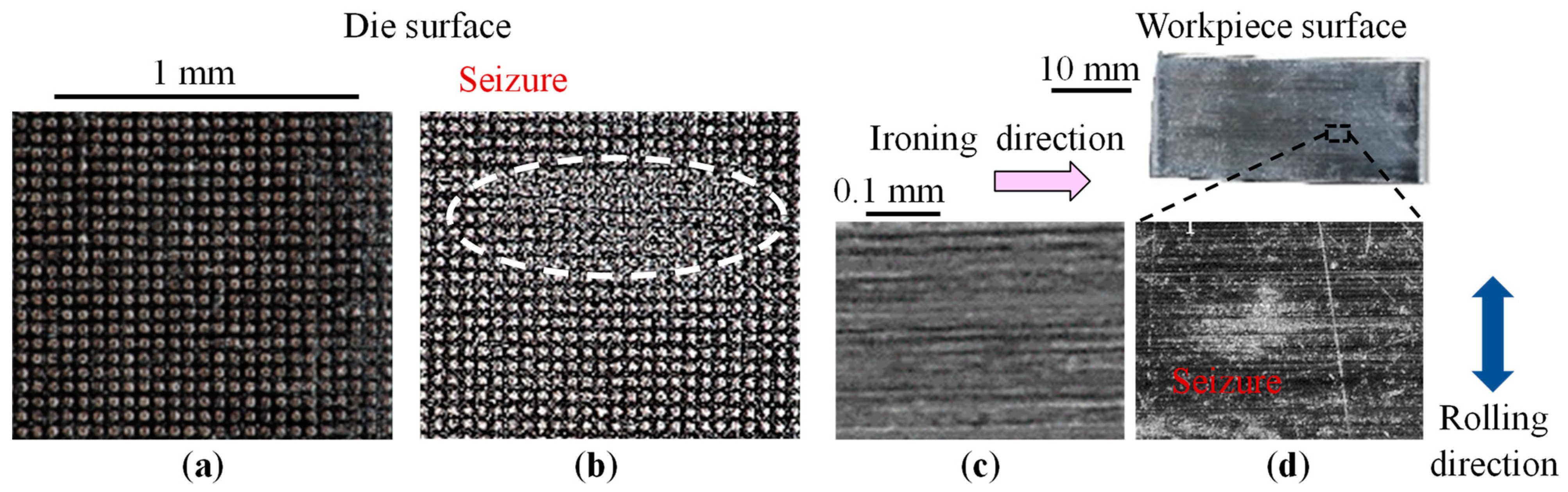
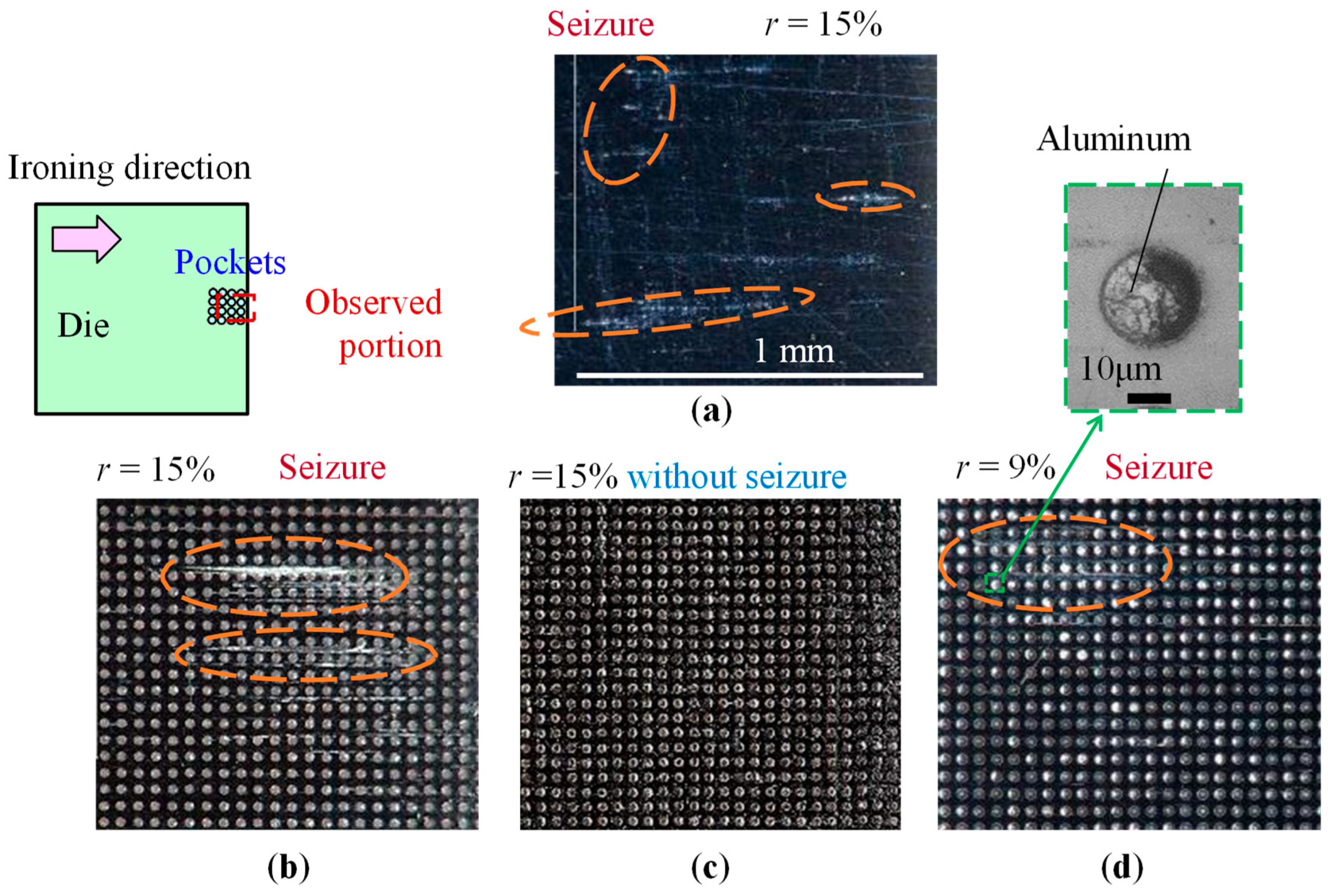
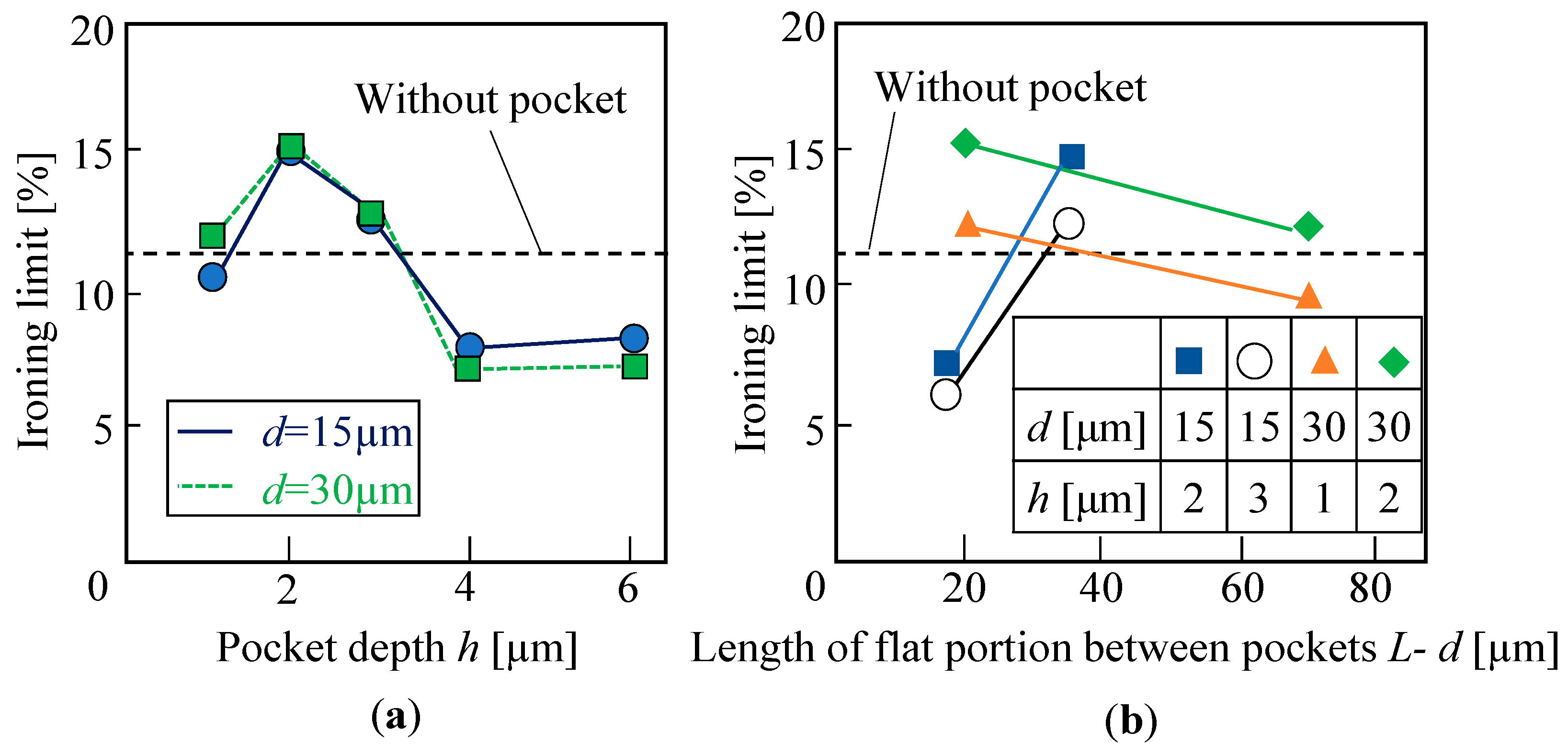
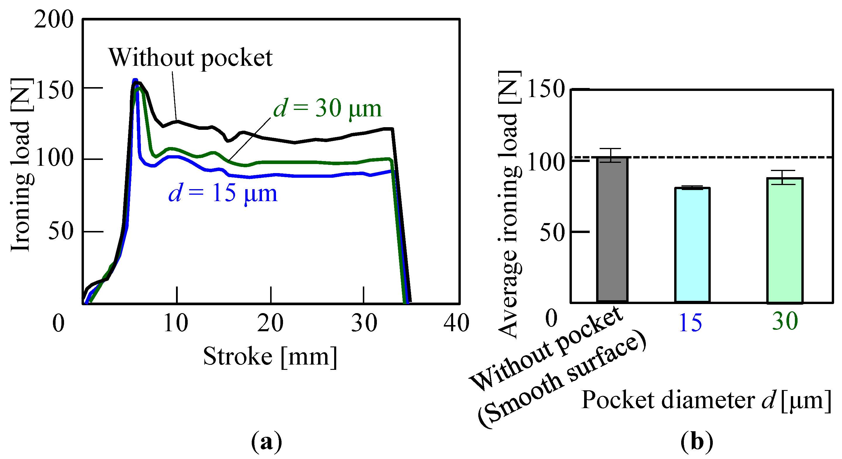
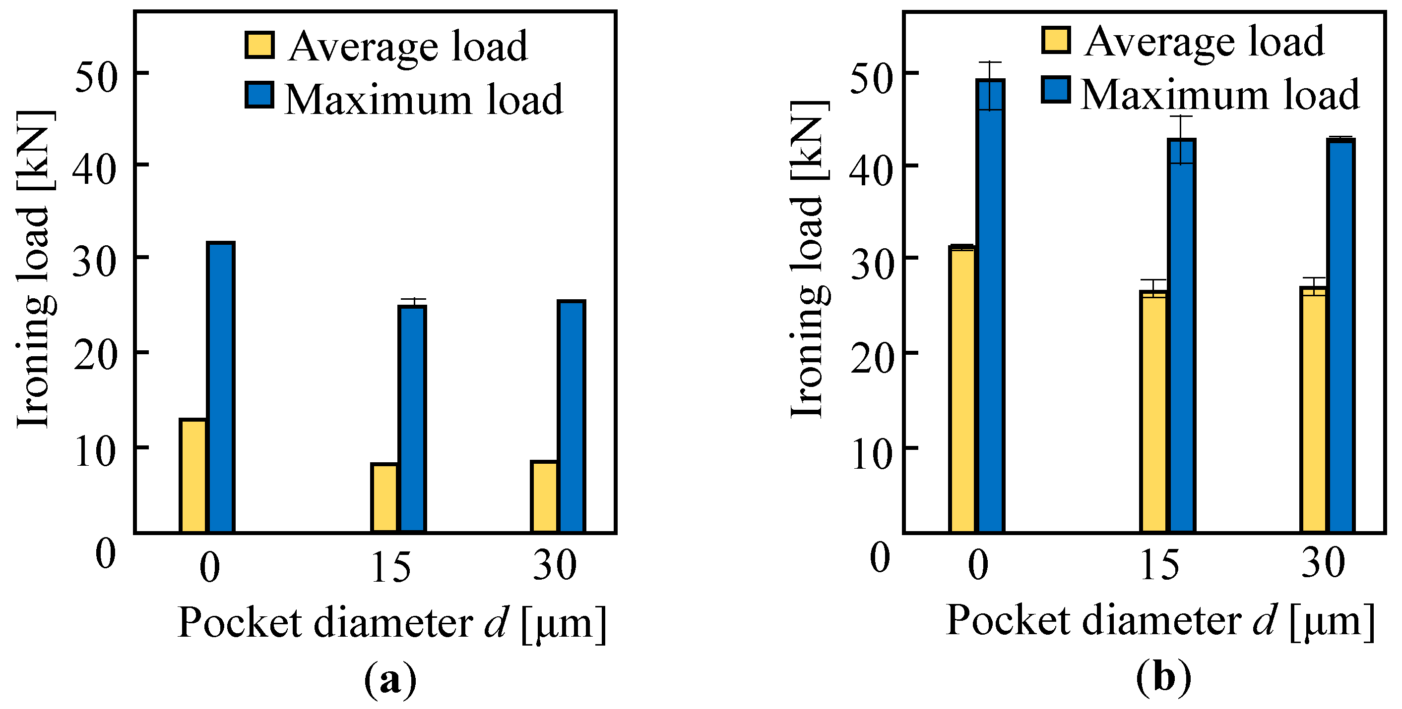
  • In the strip ironing of aluminum alloy sheets, texturing the suitable circular pockets on the die surface improved seizure resistance. The ironing limit was increased by 4%, and the average ironing load decreased by 20% compared to the smooth surface without a pocket.
  • The optimum array pattern of the lubricant pockets was the grid array pattern with a diameter of 15 and 30 µm, a depth of 2 µm, and the length of the flat portion between the pockets between 20 and 35 µm.
  • For the crossing array pattern, the length of the flat portion between pockets in the ironing direction was too long, and for the grooved array pattern, the direct contact between the die-workpiece interface occurred, after which the ironing limits of both array patterns were equal to or lower than the smooth surface without a pocket.
  • In the ironing of the SUS430 stainless steel cup by using a textured die with an optimum array pattern of lubricant pockets and the lubricant without the extreme pressure additive, the ironing limit increased about 6% and the average ironing load reduced by 35% in comparison with the untextured die.
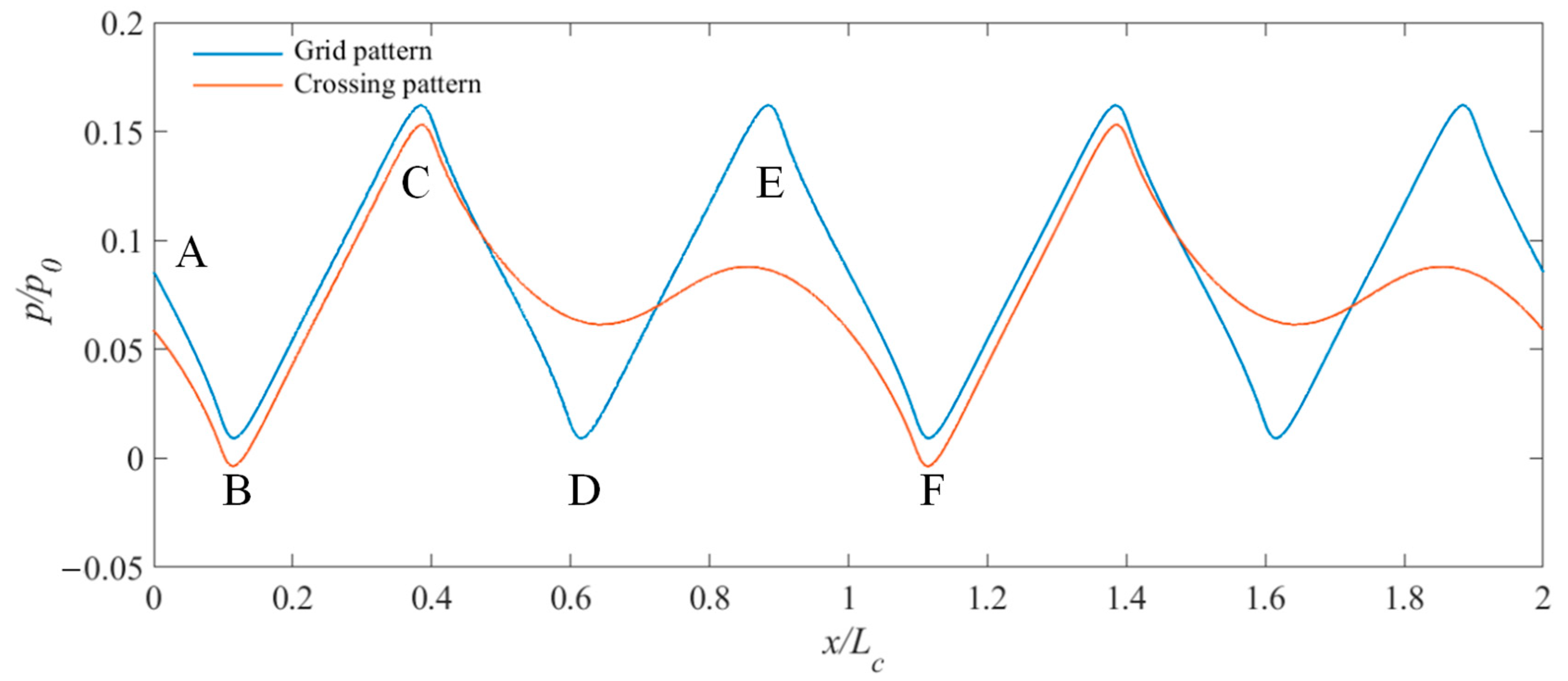
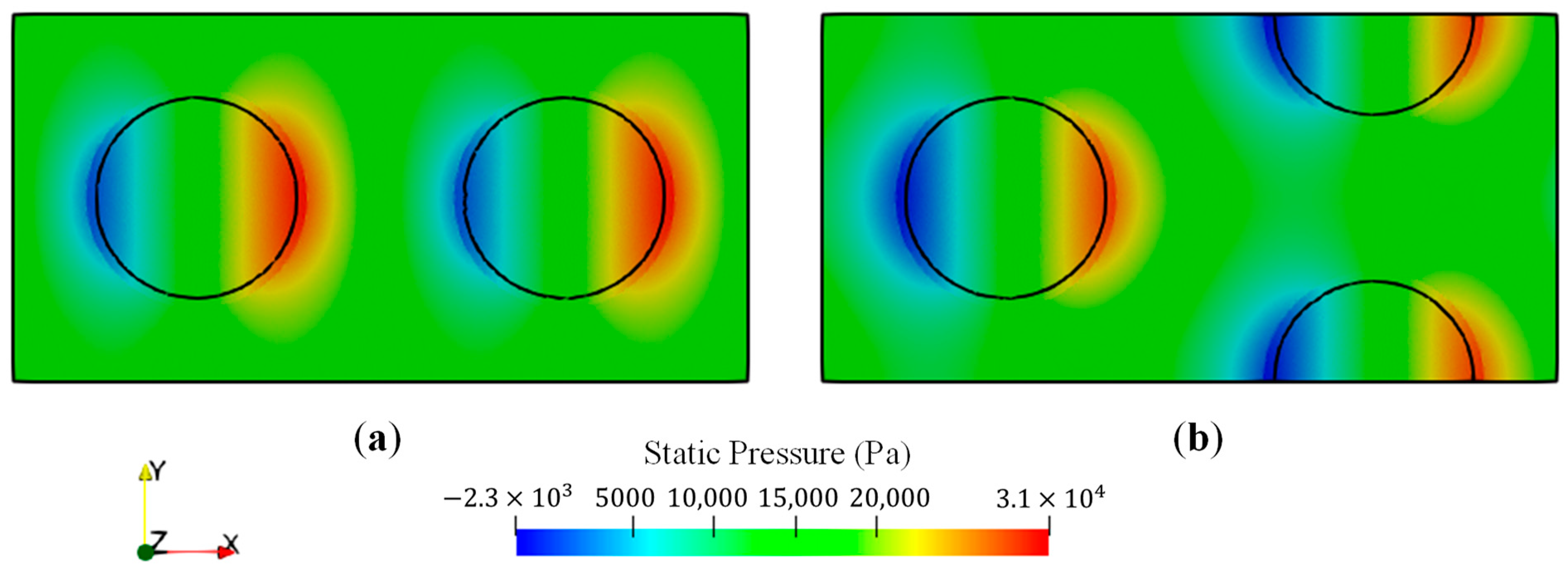
  • Computational fluid dynamics simulations, based on the Navier-Stokes equations, were performed to assess the tribological behaviours and characteristics between micro-pocket textured surfaces under hydrodynamic lubrication. The tribological characteristics of the grid and crossing array patterns of a micro-pocket textured die surface were compared. It was shown that the load-carrying force F z * of the grid array pattern is greater than that of the crossing array pattern, while the shear force F d * is roughly the same magnitude for both array patterns. As a consequence, the friction coefficient f becomes lower for the grid array pattern due to an increase in the load-carrying capacity F z * .
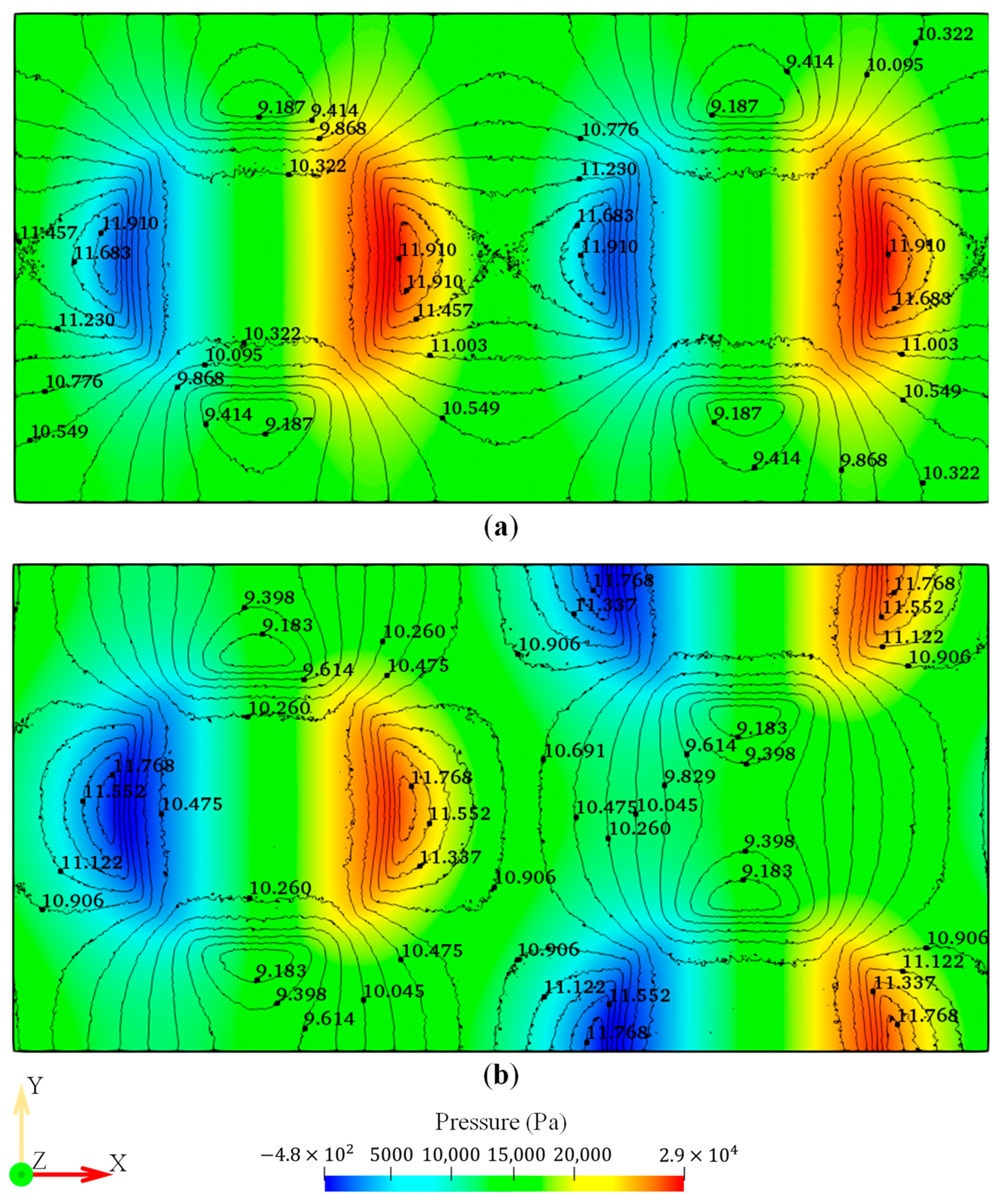
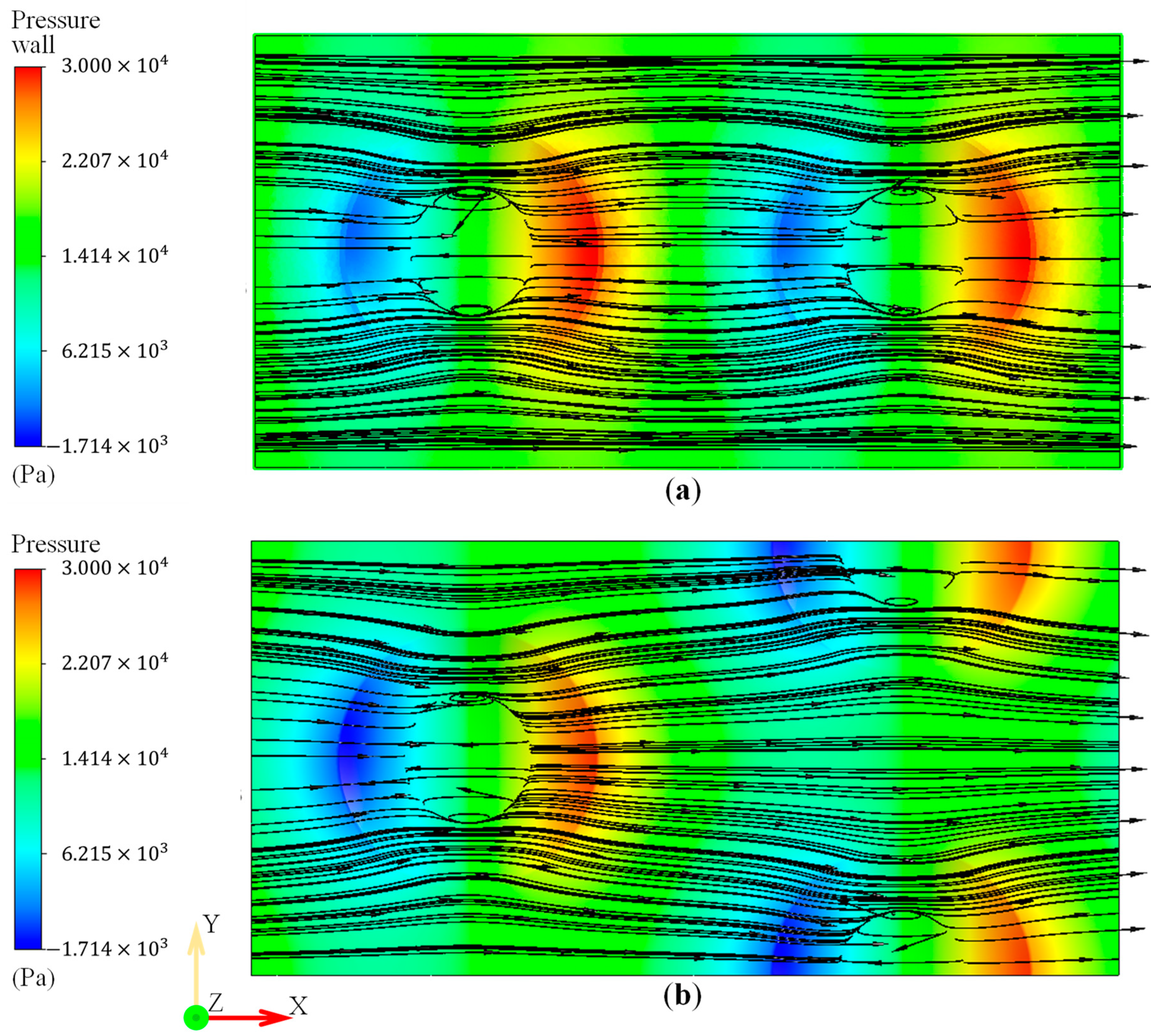
  • The presence of micro-pocket units plays an important role in the redistribution of velocity and pressure fields under hydrodynamic lubrication. Higher velocity zones appear due to the curvature of surfaces at the entrance and exit of the micro-pocket units, corresponding to the negative and positive pressure areas, respectively. The convergence of streamlines appears at the entrance of the micro-pocket units connected to the negative pressure zones, while the divergence of streamlines presents at the exit of micro-pocket units connected to the positive pressure zones. Physical mechanisms related to an improvement in the load-carrying capacity with the presence of micro-pocket units remains an open question.
Further investigation is needed to understand the generation mechanisms of the static (hydrodynamic) pressure on the micro-pocket textured surfaces with different array patterns.

Author Contributions

Conceptualization, Y.A. and K.-i.M.; methodology, K.S., Y.A. and K.-i.M.; software, P.K.; validation, K.S. and P.K.; formal analysis, K.S., P.K., Y.A. and W.D.; investigation, M.S. and T.A.; writing—original draft preparation, W.D. and K.S.; writing—review and editing, W.D., K.S. and Y.A.; visualization, T.A., K.S. and M.S.; supervision, Y.A. and K.-i.M.; project administration, Y.A.; funding acquisition, Y.A. All authors have read and agreed to the published version of the manuscript.

Funding

This research was supported in part by the Japanese Ministry of Education, Culture, Sports, Science and Technology with Grant-in-Aid for Scientific Research C (No. 19K05095).

Data Availability Statement

Not applicable.

Acknowledgments

The authors would like to express their appreciation to L.P.S. Works Co., Ltd. and Nihon Kohsakuyu Co., Ltd. for their technical assistance.

Conflicts of Interest

The authors declare that they have no conflict of interest.

References

  1. Kleiner, M.; Geiger, M.; Klaus, A. Manufacturing of lightweight components by metal forming. CIRP Ann. 2003, 52, 521–542. [Google Scholar] [CrossRef]
  2. Park, C.S.; Ku, T.W.; Kang, B.S.; Hwang, S.M. Process design and blank modification in the multistage rectangular deep drawing of an extreme aspect ratio. J. Mater. Process. Technol. 2004, 153–154, 778–784. [Google Scholar] [CrossRef]
  3. Kim, S.H.; Chung, S.W.; Padmanaban, S. Investigation of lubrication effect on the backward extrusion of thin-walled rectangular aluminum case with large aspect ratio. J. Mater. Process. Technol. 2006, 180, 185–192. [Google Scholar] [CrossRef]
  4. Inoue, Y.; Yamaguchi, M. Effect of plastic anisotropy on ironing formability of 3104 aluminum alloy hard sheets. Mater. Trans. 2021, 62, 1471–1478. [Google Scholar] [CrossRef]
  5. Cui, J.; Sun, S.; An, H.; Ou, H.; Li, G. Effect of ironing on forming characteristics in the Lorentz-force-driven hole flanging process. J. Mater. Process. Technol. 2022, 301, 117442. [Google Scholar] [CrossRef]
  6. Bay, N.; Azushima, A.; Groche, P.; Ishibashi, I.; Merklein, M.; Morishita, M.; Nakamura, T.; Schmid, S.; Yoshida, M. Environmentally benign tribo-systems for metal forming. CIRP Ann. 2010, 59, 760–780. [Google Scholar] [CrossRef]
  7. Lu, X.; Khonsari, M.M. An experimental investigation of dimple effect on the Stribeck curve of journal bearings. Tribol. Lett. 2007, 27, 169–176. [Google Scholar] [CrossRef]
  8. Etsion, I.; Halperin, G.; Brizmer, V.; Kligerman, Y. Experimental investigation of laser surface textured parallel thrust bearings. Tribol. Lett. 2004, 17, 295–300. [Google Scholar] [CrossRef]
  9. Etsion, I.; Burstein, L. A model for mechanical seals with regular microsurface structure. Tribol. Trans. 1996, 39, 677–683. [Google Scholar] [CrossRef]
  10. Steinhoff, K.; Rasp, W.; Pawelski, O. Development of deterministic-stochastic surface structures to improve the tribological conditions of sheet forming processes. J. Mater. Process. Technol. 1996, 60, 355–361. [Google Scholar] [CrossRef]
  11. Bech, J.; Bay, N.; Eriksen, M. Entrapment and escape of liquid lubricant in metal forming. Wear 1999, 232, 134–139. [Google Scholar] [CrossRef]
  12. Costa, H.L.; Hutchings, I.M. Effects of die surface patterning on lubrication in strip drawing. J. Mater. Process. Technol. 2009, 209, 1175–1180. [Google Scholar] [CrossRef]
  13. Aramaki, M.; Yamada, N.; Furukimi, O. Effect of combined shot treatment and nitriding on galling property of die used for high strength steels. ISIJ Int. 2011, 51, 1137–1141. [Google Scholar] [CrossRef]
  14. Furukimi, O.; Aramaki, M.; Abe, K.; Fukaura, H.; Yamada, N. Improvement of die life with surface texture control and solid lubricant. HTM J. Heat Treat. Mater. 2012, 67, 153–157. [Google Scholar] [CrossRef]
  15. Podgornik, B.; Jerina, J. Surface topography effect on galling resistance of coated and uncoated tool steel. Surf. Coat. Technol. 2012, 206, 2792–2800. [Google Scholar] [CrossRef]
  16. Abe, Y.; Mori, K.; Hatashita, F.; Shiba, T.; Daodon, W.; Osakada, K. Improvement of seizure resistance in ironing of stainless steel cup with cermet die having fine lubricant pockets. J. Mater. Process. Technol. 2016, 234, 195–207. [Google Scholar] [CrossRef]
  17. Gachot, C.; Rosenkranz, A.; Hsu, S.M.; Costa, H.L. A critical assessment of surface texturing for friction and wear improvement. Wear 2017, 372–373, 21–41. [Google Scholar] [CrossRef]
  18. Geiger, M.; Popp, U.; Engel, U. Excimer laser micro texturing of cold forging tool surfaces—Influence on tool life. CIRP Ann. 2002, 51, 231–234. [Google Scholar] [CrossRef]
  19. Wakuda, M.; Yamauchi, Y.; Kanzaki, S.; Yasuda, Y. Effect of surface texturing on friction reduction between ceramic and steel materials under lubricated sliding contact. Wear 2003, 254, 356–363. [Google Scholar] [CrossRef]
  20. Schneider, J.; Braun, D.; Greiner, C. Laser Textured Surfaces for Mixed Lubrication: Influence of Aspect Ratio, Textured Area and Dimple Arrangement. Lubricants 2017, 5, 32. [Google Scholar] [CrossRef]
  21. Daodon, W.; Saetang, V. Improvement of frictional property of AISI D2 tool steel surface against JIS SPFC 980Y advanced high-strength steel by using laser texturing process. Lubricants 2023, 11, 68. [Google Scholar] [CrossRef]
  22. Vilhena, L.M.; Sedlaček, M.; Podgornik, B.; Vižintin, J.; Babnik, A.; Možina, J. Surface texturing by pulsed Nd:YAG laser. Tribol. Int. 2009, 42, 1496–1504. [Google Scholar] [CrossRef]
  23. Meng, F.; Zhou, R.; Davis, T.; Cao, J.; Wang, Q.J.; Hua, D.; Liu, J. Study on effect of dimples on friction of parallel surfaces under different sliding conditions. Appl. Surf. Sci. 2010, 256, 2863–2875. [Google Scholar] [CrossRef]
  24. Shimizu, T.; Kobayashi, H.; Vorholt, J.; Yang, M. Lubrication analysis of micro-dimple textured die surface by direct observation of contact interface in sheet metal forming. Metals 2019, 9, 917. [Google Scholar] [CrossRef]
  25. Conradi, M.; Kocijan, A.; Klobčar, D.; Podgornik, B. Tribological response of laser-textured Ti6Al4V alloy under dry conditions and lubricated with Hank’s solution. Tribol. Int. 2021, 160, 107049. [Google Scholar] [CrossRef]
  26. Gaikwad, A.; Vázquez-Martínez, J.M.; Salguero, J.; Iglesias, P. Tribological properties of Ti6Al4V titanium textured surfaces created by laser: Effect of dimple density. Lubricants 2022, 10, 138. [Google Scholar] [CrossRef]
  27. Hamilton, D.B.; Walowit, J.A.; Allen, C.M. A theory of lubrication by micro-irregularities. J. Basic Eng. 1966, 88, 177–185. [Google Scholar] [CrossRef]
  28. Brizmer, V.; Kligerman, Y.; Etsion, I. A laser surface textured parallel thrust bearing. Tribol. Trans. 2003, 46, 397–403. [Google Scholar] [CrossRef]
  29. Baum, M.J.; Heepe, L.; Gorb, S.N. Friction behavior of a microstructured polymer surface inspired by snake skin. Beilstein J. Nanotechnol. 2014, 5, 83–97. [Google Scholar] [CrossRef]
  30. Uddin, M.S.; Ibatan, T.; Shankar, S. Influence of surface texture shape, geometry and orientation on hydrodynamic lubrication performance of plane-to-plane slider surfaces. Lubr. Sci. 2016, 29, 153–181. [Google Scholar] [CrossRef]
  31. Pascovici, M.D.; Cicone, T.; Fillon, M.; Dobrica, M.B. Analytical investigation of a partially textured parallel slider. Proc. Inst. Mech. Eng. Part J J. Eng. Tribol. 2008, 223, 151–158. [Google Scholar] [CrossRef]
  32. Li, J.; Chen, H. Evaluation on applicability of Reynolds equation for squared transverse roughness compared to CFD. J. Tribol. 2007, 129, 963–967. [Google Scholar] [CrossRef]
  33. Qiu, M.; Bailey, B.N.; Stoll, R.; Raeymaekers, B. The accuracy of the compressible Reynolds equation for predicting the local pressure in gas-lubricated textured parallel slider bearings. Tribol. Int. 2014, 72, 83–89. [Google Scholar] [CrossRef]
  34. Sun, S.; Brandt, M. Laser beam machining. In Nontraditional Machining Processes; Davim, J.P., Ed.; Springer: London, UK, 2013; pp. 35–96. [Google Scholar]
  35. Nawa, M.; Kitamura, K. Evaluation of Effect of Micro-dimples in Lubrication Using Ball Penetration Test. In Proceedings of the 63rd Japanese Joint Conference for the Technology of Plasticity, Kitakyushu, Japan, 4–6 November 2012; pp. 257–258. (In Japanese). [Google Scholar]
  36. Kobayashi, H.; Shimizu, T.; Vorholt, J.; Yang, M. Evaluation of Lubrication Properties of Textured Surface by In-situ Observation using Silica Glass Die. In Proceedings of the 68th Japanese Joint Conference for the Technology of Plasticity, Fukui, Japan, 9–12 November 2017; pp. 191–192. (In Japanese). [Google Scholar]
  37. Kovalchenko, A.; Ajayi, O.; Erdemir, A.; Fenske, G.; Etsion, I. The effect of laser surface texturing on transitions in lubrication regimes during unidirectional sliding contact. Tribol. Int. 2005, 38, 219–225. [Google Scholar] [CrossRef]
  38. Li, K.; Jing, D.; Hu, J.; Ding, X.; Yao, Z. Numerical investigation of the tribological performance of micro-dimple textured surfaces under hydrodynamic lubrication. Beilstein J. Nanotechnol. 2017, 8, 2324–2338. [Google Scholar] [CrossRef]
  39. Ding, S.; Xu, J.; Liu, P.; Shi, Z.; Yang, O.; Hu, Y. Geometric influence on friction and wear performance of cast iron with a micro-dimpled surface. Results Eng. 2021, 9, 100211. [Google Scholar] [CrossRef]
  40. Scaraggi, M.; Mezzapesa, F.P.; Carbone, G.; Ancona, A.; Sorgente, D.; Lugarà, P.M. Minimize friction of lubricated laser-microtextured-surfaces by tuning microholes depth. Tribol. Int. 2014, 75, 123–127. [Google Scholar] [CrossRef]
  41. Wang, X.; Wang, J.; Zhang, B.; Huang, W. Design principles for the area density of dimple patterns. Proc. Inst. Mech. Eng. Part J J. Eng. Tribol. 2014, 229, 538–546. [Google Scholar] [CrossRef]
  42. Adatepe, H.; Bıyıklıoglu, A.; Sofuoglu, H. An experimental investigation on frictional behavior of statically loaded micro-grooved journal bearing. Tribol. Int. 2011, 44, 1942–1948. [Google Scholar] [CrossRef]
  43. Groche, P.; Nitzsche, G. Influence of temperature on the initiation of adhesive wear with respect to deep drawing of aluminum-alloys. J. Mater. Process. Technol. 2007, 191, 314–316. [Google Scholar] [CrossRef]
Figure 1. Schematic illustration of array patterns of micro-lubricant pockets: (a) grid, (b) crossing, and (c) grooved array patterns.
Metals 13 00803 g001
Figure 2. Micrographs and 2D profiles of array patterns of micro-lubricant pockets: grid array pattern having d = 15 µm, h = 2 µm (a) L = 33 µm and (b) L = 50 µm; (c) crossing array pattern having d = 15 µm, h = 2 µm, L = 50 µm; (d) grooved array pattern having d = 15 µm, h = 2 µm, L = 50 µm.
Metals 13 00803 g002
Figure 3. Strip ironing of aluminum alloy sheets illustrated in half-section view (scale in mm).
Metals 13 00803 g003
Figure 4. Ironing conditions for SUS430 stainless steel cylindrical cups and die surfaces.
Metals 13 00803 g004
Figure 5. Geometrical model of the simplified contacting couple and the computational fluid domain with micro-lubricant pockets: (a) side view; (b) top view (grid array pattern); (c) top view (crossing array pattern).
Metals 13 00803 g005aMetals 13 00803 g005b
Figure 6. Static pressure distribution on the middle section of the micro-pocket unit at different Reynolds numbers [38].
Metals 13 00803 g006
Figure 7. Fluid domain and boundary conditions of a two parallel contacting couple between the die and the workpiece with thin-film lubrication.
Metals 13 00803 g007
Figure 8. Computational mesh of fluid domain with micro-pocket textured surface.
Metals 13 00803 g008
Figure 9. Optical micrograph of the die and workpiece surfaces after ironing with grid array pattern, d = 30 µm, h = 2 µm and L = 50 µm: (a) die surface without seizure at r = 15%; (b) seizure on die surface at r = 18%; (c) workpiece surface without seizure at r = 15%; and (d) seizure on workpiece surface at r = 18%.
Metals 13 00803 g009
Figure 10. Occurrence of seizure on die with (a) smooth surface at r = 15% and with grid array pattern, d = 30 µm, L = 50 µm, pocket depth h of (b) 1 µm at r = 15%, (c) 2 µm at r = 15%, and (d) 6 µm at r = 9%.
Metals 13 00803 g010
Figure 11. Effect of (a) pocket depth at L = 50 µm and (b) length of flat portion between pockets on the ironing limit with grid array pattern.
Metals 13 00803 g011
Figure 12. Ironing load of aluminum alloy sheets with grid array patterns, h = 2 µm, L = 50 µm and r = 10%: (a) load-travel diagram and (b) average ironing load.
Metals 13 00803 g012
Figure 13. Occurrence of seizure on die with (a) smooth surface at r = 15%, and with crossing array pattern, h = 2 µm, L = 50 µm, pocket diameter d of (b) 15 µm at r = 15%, and (c) d of 30 µm at r = 12%.
Metals 13 00803 g013
Figure 14. Occurrence of seizure on die with (a) smooth surface at r = 15% and with grooved array pattern, h = 2 µm, L = 50 µm, groove width d of (b) 15 µm at r = 7%, and (c) 30 µm at r = 6%.
Metals 13 00803 g014
Figure 15. Ironing limit of die having lubricant pockets with different array patterns, h = 2 µm and L = 50 µm.
Metals 13 00803 g015
Figure 16. Stainless steel cup obtained after ironing with a grid array pattern having d = 30 µm, h = 2 µm, and L = 50 µm, applying lubricant containing an extreme pressure additive at (a) r = 17%, and (b) at r = 23%.
Metals 13 00803 g016
Figure 17. The die surface before ironing and the cup surface obtained after ironing with a grid array pattern having d = 30 µm, h = 2 µm, and L = 50 µm, applying a lubricant containing extreme pressure additive at r = 17%; surface roughness and 2D profiles (a) on pocket marks, and (b) outside pocket marks.
Metals 13 00803 g017
Figure 18. Ironing limit of laser textured dies having lubricant pockets used to iron SUS430 stainless steel cups by applying lubricant (a) without an extreme pressure additive, and (b) with an extreme pressure additive.
Metals 13 00803 g018
Figure 19. Ironing load of laser textured dies having lubricant pockets used to iron SUS430 stainless steel cups by applying lubricant (a) without an extreme pressure additive at r = 3%, and (b) with an extreme pressure additive at r = 8%.
Metals 13 00803 g019
Figure 20. Static pressure distribution along the middle plane of the workpiece.
Metals 13 00803 g020
Figure 21. Static pressure distribution on the die surface: (a) grid array pattern; (b) crossing array pattern. The circle shows where the pockets are approximately located.
Metals 13 00803 g021
Figure 22. Static pressure distribution on the workpiece surface: (a) grid array pattern; (b) crossing array pattern.
Metals 13 00803 g022
Figure 23. Velocity (line contours) and pressure (coloured contours) distributions at the mid-plane between the die and workpiece: (a) grid array pattern; (b) crossing array pattern. Note that the unit of velocity is mm/s.
Metals 13 00803 g023
Figure 24. Streamlines and pressure (coloured contours) distributions around the die surface: (a) grid array pattern; (b) crossing array pattern.
Metals 13 00803 g024
Table 1. Geometrical parameters of array patterns of micro-pockets.
PatternsDiameter
d (µm)
Distance between Pockets L (µm)Flat Portion Length
Ld (µm)
Depth
h (µm)
Area Ratio of Pockets
(%)
Grid1533182 and 316.2
50351, 2, 3, 4 and 67.1
3050201, 2, 3, 4 and 628.3
100701 and 27.1
Crossing1550352 and 47.1
3050202 and 428.3
Grooved1550352 and 430
3050202 and 460
Table 2. Influence of mesh size on the load-carrying force F z * , the shear force F d * , and the friction coefficient f.
Mesh   Size   ( × 10 6   m )
1.000.750.500.250.18
Number of Mesh Elements366,051678,5751,517,4197,152,81614,293,507
F d * 0.019160.019170.019140.019190.01920
F z * 0.077350.069910.072960.074780.07470
f0.247720.274290.262300.256570.25710
Table 3. Properties of fluids and analytical conditions for laminar one-phase flow analysis.
Mass density of lubricant, ρliquid (kg/m3)833
Kinematic viscosity of lubricant, νlub (mm2/s)433
Sliding speed, υw (mm/s)20
Flow velocity, υf (mm/s)20
Lubricant film thickness, ht (µm)2
Atmosphere temperature, T (K)293.15
Contact angle of dropped lubricant on polished die, θ (°)20
Table 4. Comparisons of the load-carrying force F z * , the shear force F d * , and the friction coefficient f between the grid and crossing array patterns.
Grid Array PatternCrossing Array Pattern
F d * 0.019190.01920
F d , r m s * 0.019530.01954
F z * 0.085600.07470
F z , r m s * 0.091130.08128
f0.224230.25710
Disclaimer/Publisher’s Note: The statements, opinions and data contained in all publications are solely those of the individual author(s) and contributor(s) and not of MDPI and/or the editor(s). MDPI and/or the editor(s) disclaim responsibility for any injury to people or property resulting from any ideas, methods, instructions or products referred to in the content.

