1. Introduction
Welding deformations are caused by non-uniform thermal expansion and contraction by local welding heat sources during the manufacturing of welded structures, such as ships, bridges, and aircraft. These contractions and expansions cause plastic deformation owing to internal and external restraints, which appear as welding residual stresses and deformations. Welding deformation is particularly affected by the various shapes of welded structures, welding sequences, and welding conditions [
1,
2].
Laser welding, which is used to create complex structures and parts with high precision, has recently received increasing attention in the field of additive manufacturing. Ref. [
3] printed a Ti–Ni–Ti-like sandwich structure using the direct energy deposition method. A laser beam was used to melt and fuse layers of Ti and Ni to create a sandwich structure with unique properties, such as high strength and shape memory. Ref. [
4] developed a model to predict the deformation of a lattice support structure in the laser-powder bed fusion additive manufacturing process using the eigenstrain method and efficiently predicted the deformation and residual stress. Ref. [
5] investigated the effects of direct aging and annealing on the microstructure and mechanical properties of Al–Si–10Mg, produced by selective laser melting. A laser was used to melt and fuse layers of an Al–Si alloy to create a part with high strength and excellent corrosion resistance. Ref. [
6] developed an anti-deformation model to improve the manufacturing accuracy of built-in channels using selective laser melting and demonstrated that increased channel length and depth led to increased deformation and decreased distortion, respectively.
When the shape of a welded structure is cylindrical (as in this study), and bending occurs on the appearance of the structure owing to welding deformation [
7,
8], it causes aerodynamic resistance as well as affecting other structures in the manufacturing process because of the mismatch in the welded part. These welding deformations generally occur in thin structures rather than in thick structures [
9]. Therefore, laser welding with a low heat input is performed in thin-plate structures to minimize welding deformation. However, welding deformation—depending on the shape and welding position of the welded structure—cannot be avoided. Various studies have been conducted to predict or prevent welding deformation by analyzing the generation mechanism of welding deformation [
10,
11]. Methods to prevent welding deformation include the inverse deformation method [
12], cooling method [
13], welding sequence method [
14], and pre-stress method [
15,
16]. The effects of the anti-deformation methods depend on the shape, thickness, and welding process of the structure. Therefore, these methods should be selected carefully based on the characteristics of the welded structure.
Ref. [
17] used a numerical analysis method to minimize welding deformation during circumferential welding by splitting the entire weld length and measuring the change in diameter at three locations in the weld. When the total welding length was further divided, the diametrical welding deformation decreased. Ref. [
15] confirmed sensitization at the welded part when linear heating was used to correct welding deformation during the manufacturing of a vacuum container with STS304. Therefore, the tensile method was analytically investigated to minimize welding deformation instead of correcting this via linear heating. The transverse shrinkage and angular strain were reduced by 80% when the tensile stress was approximately 0.05% of the yield stress of the parent metal.
Ref. [
18] analyzed welding deformation and identified the causes of its occurrence to control the deformation during the manufacturing of a cylindrical welded structure with a diameter of approximately 22 mm, which was used for an offshore plant platform. The entire welding length in the circumferential direction was divided into small sections, and thermo-elastoplastic analysis was performed to analyze and control the deformation behavior. Consequently, the magnitude of deformation was significantly reduced in the case of back-step welding; however, no significant difference was observed in deformation reduction by split welding when the total length of the welded part was divided into four or eight sections. The lowest welding deformation occurred when the total welding length was divided into four sections and symmetrically welded simultaneously.
Ref. [
19] derived a relationship between welding deformation and restraint in fillet and butt welds. The degree of restraint was determined through experiments and finite-element analysis. A welding deformation prediction system was developed based on the deformation sequence of large steel structures. In other studies, the effects of welding deformation-prevention jigs were investigated for minimizing welding deformation in construction machinery structures by changing the position and spacing of the constraint jigs. [
20,
21,
22,
23,
24] performed finite-element analysis to investigate the effect of clamp removal time on the welding residual stress and welding deformation during the one-pass butt welding of an STS304-based structure. The residual stress and angular deformation were slightly affected by the removal of the clamp immediately after welding was completed. However, when the clamp was removed once the temperature of the welded part reached room temperature, the residual stress was opposite to that in the free state and welding deformation barely occurred.
Studies on planar structures and arc welding processes have been widely reported in the literature [
22,
25]; however, studies on preventing deformation during laser welding of cylindrical structures by thermo-elastoplastic analysis are not available—except for the one reported by Lee et al., 2020. Furthermore, studies on preventing deformation during the laser welding of thin cylindrical structures [
26] are limited. In addition, the reduction effect of welding deformation using thermo-elastoplastic analysis was examined through simulation by Ref. [
27]; therefore, experimental investigations on its field applicability are required.
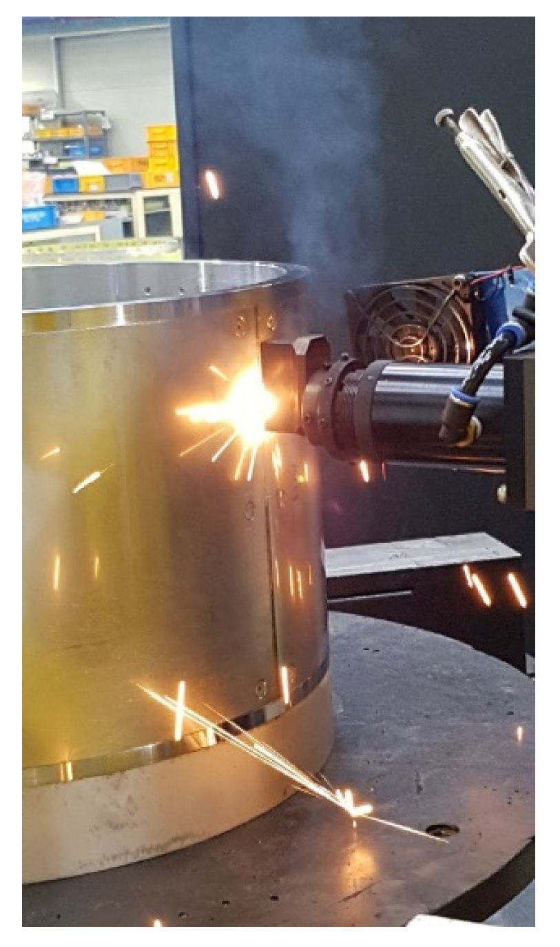
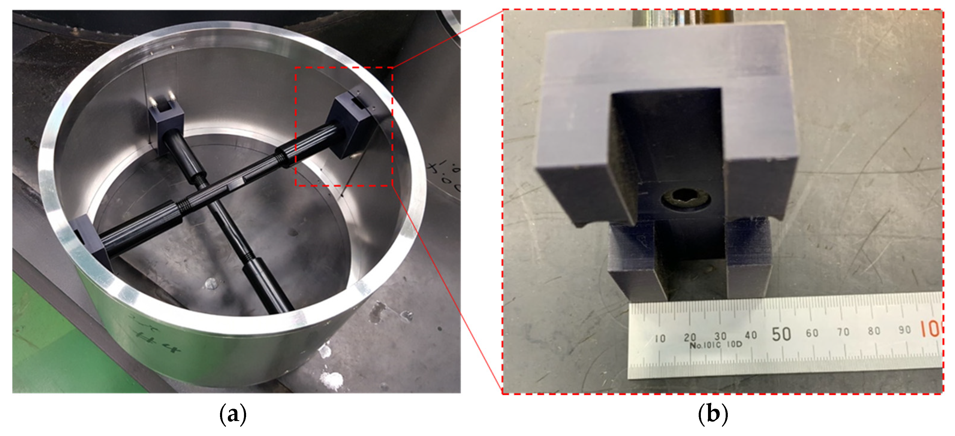
Herein, a deformation-prevention jig that pushes the cylindrical shell from the inside of the cylinder was developed and reductions in welding deformation during the manufacturing of a cylindrical structure with STS304 by laser welding was confirmed through experiments. Furthermore, experiments were conducted with and without pre-stress to investigate the effects of tensile stress on welding deformation. The results were compared with the results of a thermo-elastoplastic analysis reported in literature. The results obtained through experimental and thermo-elastoplastic analysis indicated that tensile stress can be induced in the actual cylinder and welding deformation can be reduced using a welding deformation-prevention jig.
2. Transient Thermo-Elastoplastic Analysis Using the Pre-Stress Method
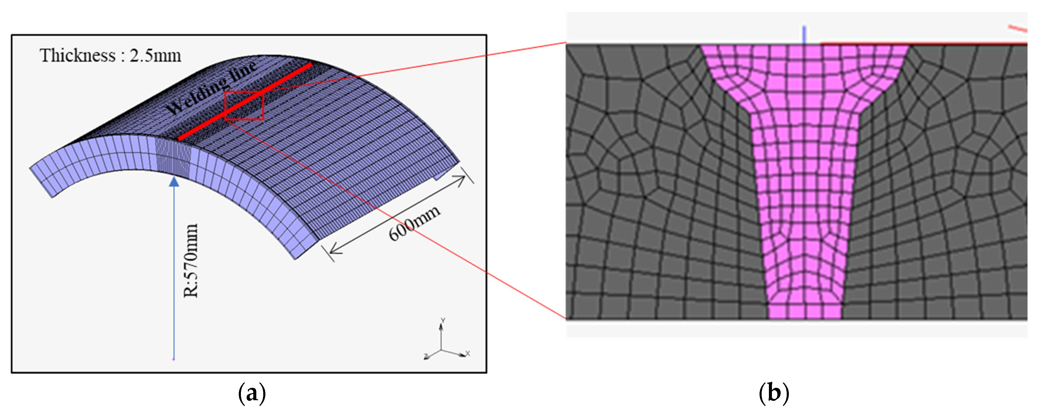
A thermo-elastoplastic analysis was conducted using the 1/4 analysis model (
Figure 1a) to reduce deformation occurring at the seam weld of the cylindrical steel structure [
27]. The length and radius (R) of the analysis model were 600 and 570 mm, respectively. The thicknesses of the skin and back plates were 2.5 and 2 mm, respectively. The skin and back plates were fastened using fasteners at intervals of 100 mm.
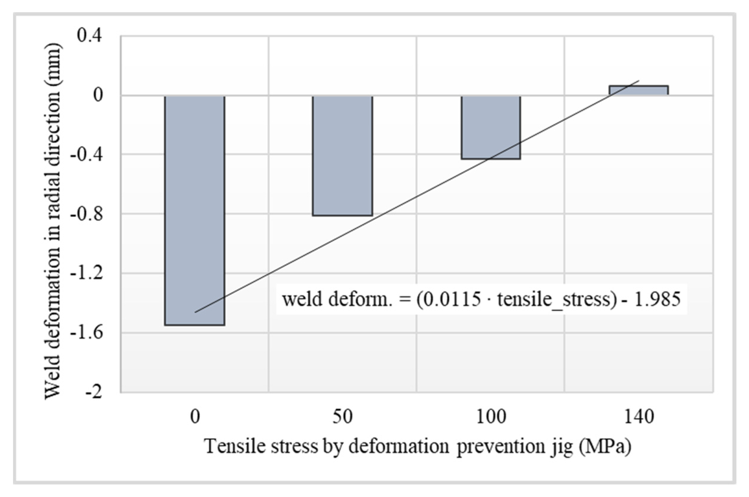
To reduce the welding deformation, a forced displacement was applied from the inside to the outside to expand the cylindrical shell, and tensile stresses of 0, 50, 100, and 140 MPa were achieved on the skin plate.
Figure 1b shows the mesh shape of the weld, which was used to model the weld in the thermo-elastoplastic analysis.
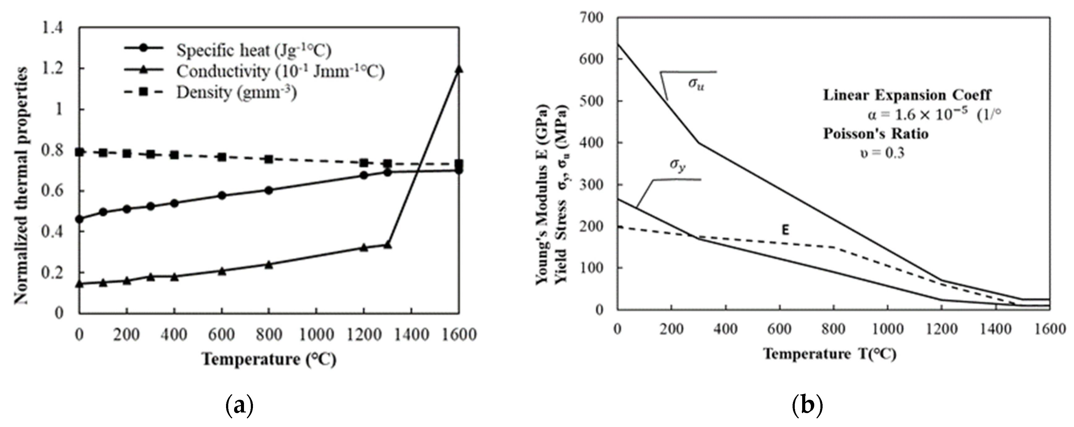
STS 304 steel was used in the analysis. Laser welding was performed at 2500 W with a welding speed of 2000 mm/min. The yield strength of the steel was 265 MPa at room temperature, tensile strength was 650 MPa, elongation was 60%, and the coefficient of linear expansion was 1.6 × 10
−5 (1/°C). The temperature-dependent physical and mechanical properties of STS304 steel are shown in
Figure 2 [
27].
To model the welding heat source, the weld flux, weld filler, and weld path options were selected in the MSC Marc 2017 software [
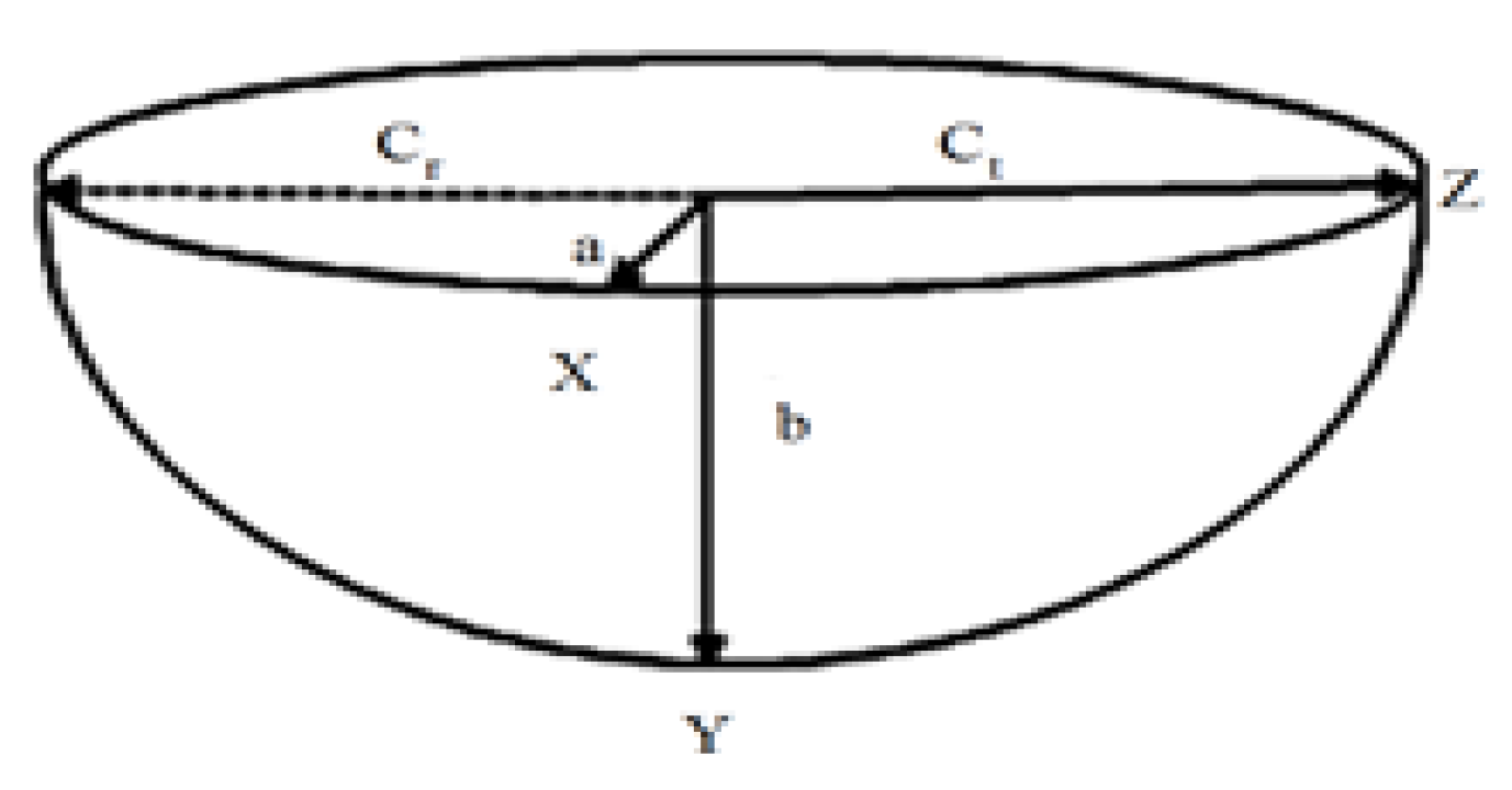
28]. A three-dimensional eight-node full-integration element model was used. The welding heat source [
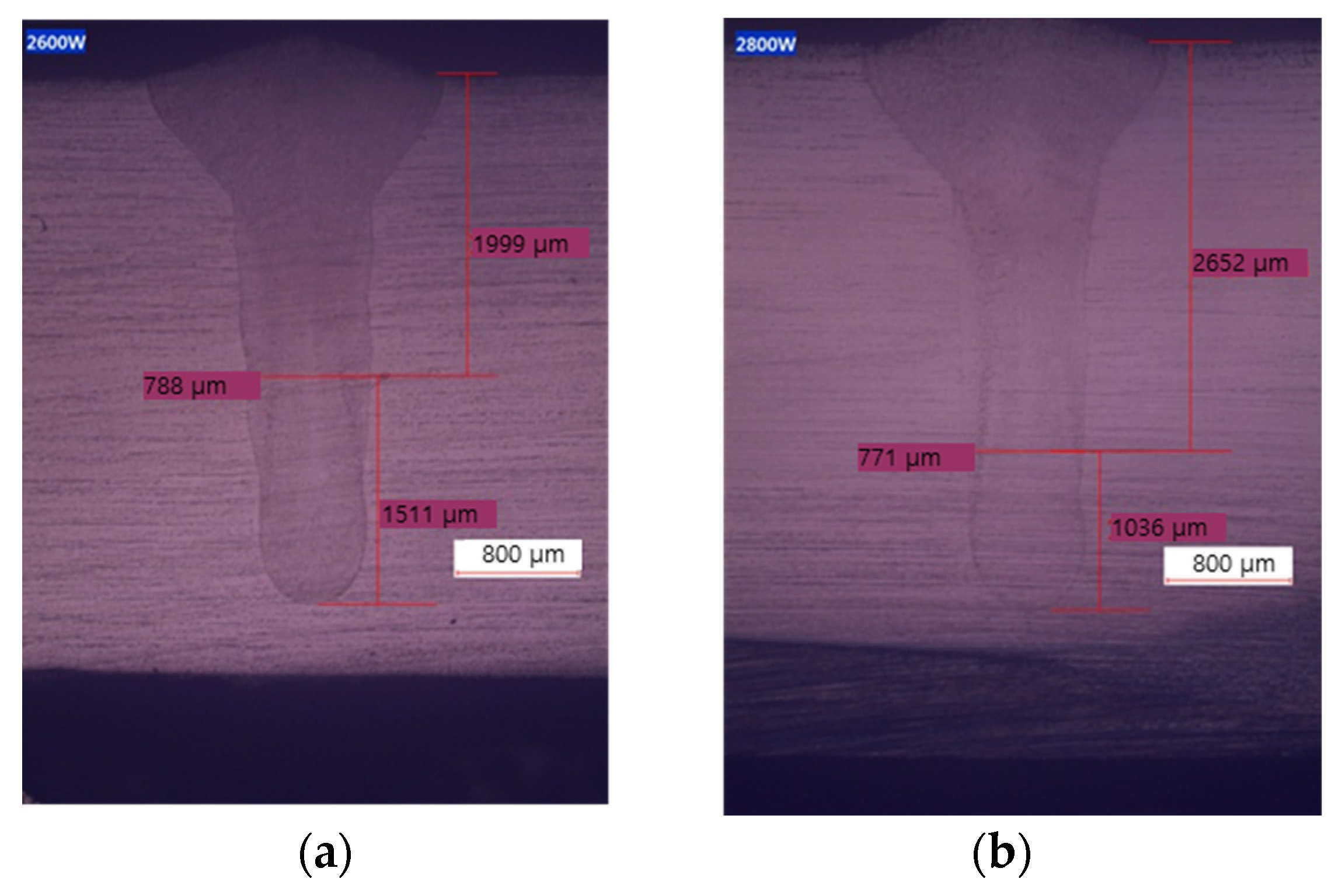
29] was modeled as a volumetric heat source (
Figure 3) using the heat source Equation (1). Data on the welding width and depth were selected based on the cross-section of the welded specimen. The welding line was set with the weld path option, and a welding wire was created when the welding heat source was moved using the weld filler option.
where
: volumetric heat input per unit of the front molten pool
: volumetric heat input per unit of the rear molten pool.
Q = ηVI: total heat input
a: x direction welding width
b: y direction welding depth
: forward molten pool length in z direction
: rear molten pool length in z direction
: dimensionless numbers
η: efficiency
V: voltage
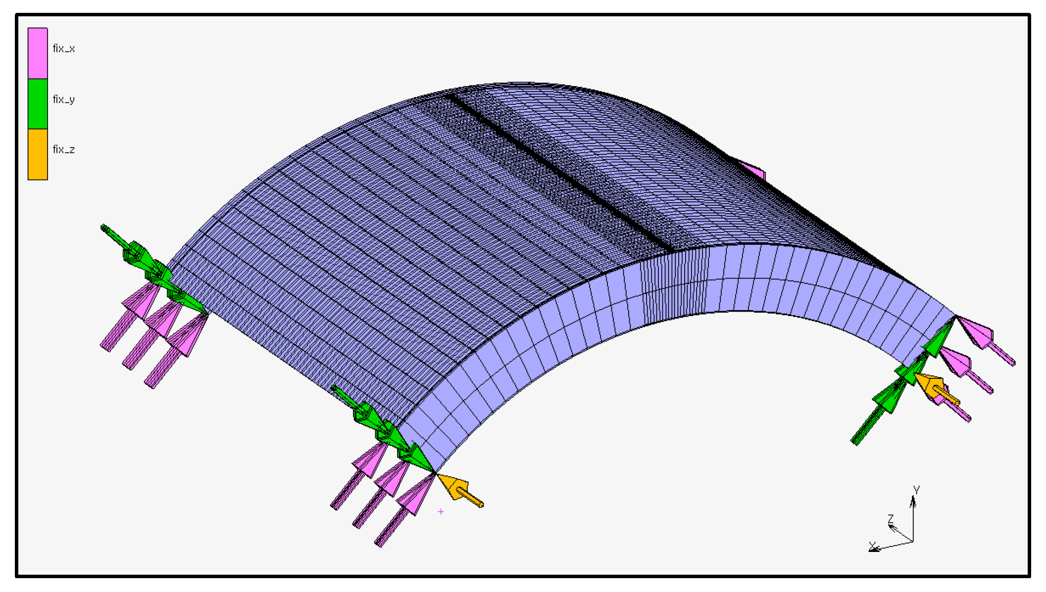
Figure 4 shows the boundary conditions used in the analysis; only the upper and lower frame sections were constrained under symmetric conditions using the local coordinates, whereas the skin plate was not constrained [
27].
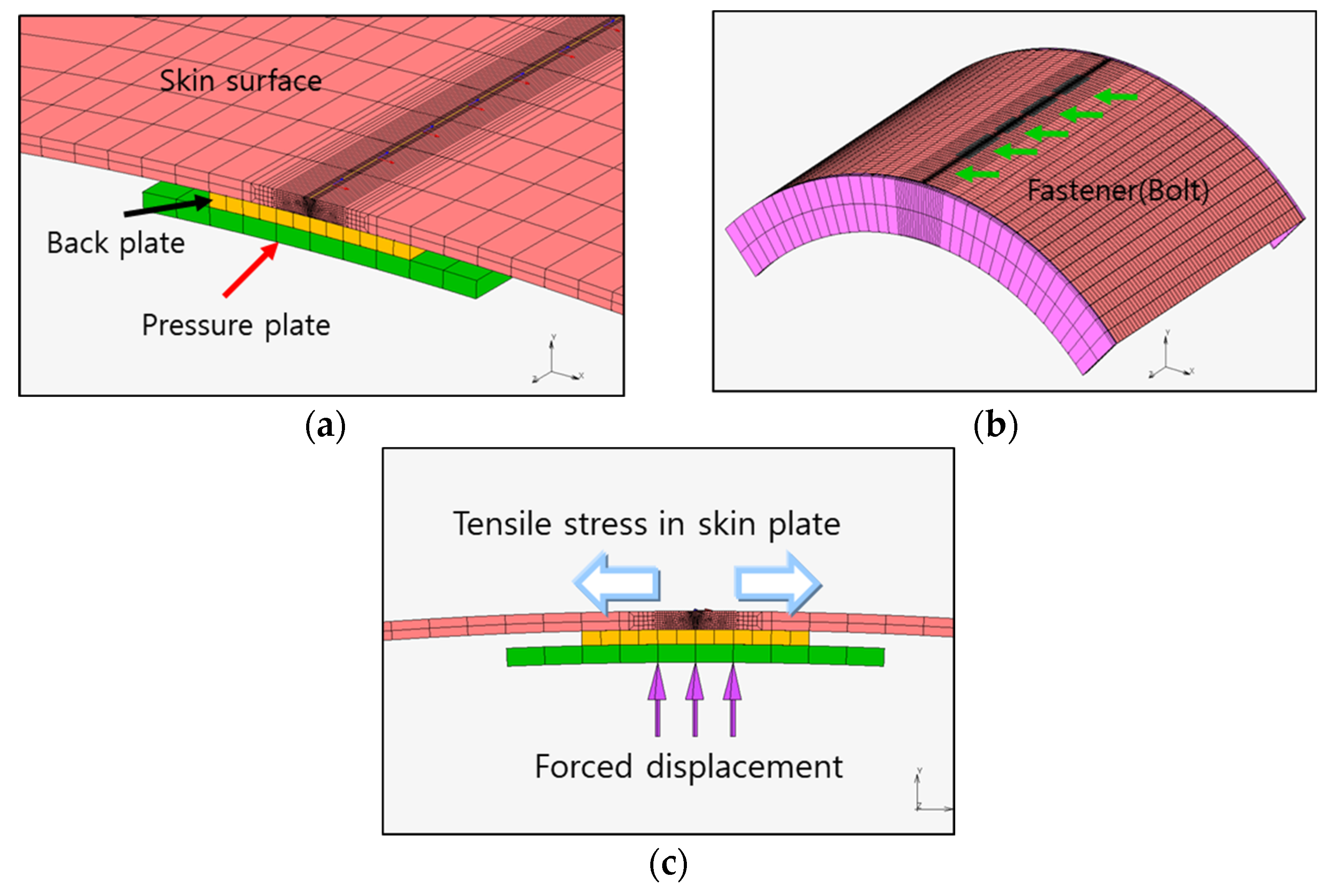
The deformation that occurred during the seam welding of the cylinder was caused by welding from the inside of the cylinder. This type of deformation is the sum of the angular deformation caused by the temperature difference between the surface and the lower section of the welded part and the longitudinal bending deformation based on the position of the neutral axis of the member. An inverse deformation or a pre-stress method was used to effectively prevent such welding deformations. Therefore, the shell was extruded from the inside to the outside during the thermo-elastoplastic analysis to induce a tensile stress on the shell. The tensile stress was applied to the shell in the thermo-elastoplastic analysis to reduce deformation (
Figure 5).
Figure 5a demonstrates the skin, back, and pressure plates. Tensile stress was induced on the skin plate by applying displacement from the inside of the cylinder. The skin plate has a seam weld, whereas the pressure plate is a rigid element that facilitates a forced displacement and is in contact with the back plate. As shown in
Figure 5b, the skin and back plates are connected to fasteners (bolts) at intervals of 100 mm in the direction of the welding line. In the thermo-elastoplastic analysis, the fastener was modeled as attached using the
glue option available in the MSC Marc 2017 software. In addition, a pressure plate was modeled to impose a forced displacement (
Figure 5c). The pressure plate transmits a forced displacement to the skin plate through contact with the back plate. The forced displacement is gradually applied before welding and subsequently removed when the welding is completed, and the welded part reaches room temperature (25 °C).
Author Contributions
Conceptualization and investigation, H.-C.J.; writing—original draft preparation and writing—review and editing, S.-H.L. and J.-U.P. All authors have read and agreed to the published version of the manuscript.
Funding
This study was supported by a research fund from the Chosun University (2021) and the Agency for Defense Development by the Korean Government (UC189015CD).
Data Availability Statement
Not applicable.
Conflicts of Interest
The authors declare no conflict of interest.
References
- Masubuchi, K. Analysis of Welded Structures: Residual Stresses, Distortion, and Their Consequences; Elsevier: Amsterdam, The Netherlands, 2013; Volume 33. [Google Scholar]
- Ma, N.; Huang, H.; Yin, X.; Guo, N. Welding distortion and inherent deformation under temporary tacking and its released states. Sci. Technol. Weld. Join. 2016, 21, 389–396. [Google Scholar] [CrossRef]
- Farzaneh, A.; Khorasani, M.; Farabi, E.; Gibson, I.; Leary, M.; Ghasemi, A.; Rolfe, B. Sandwich structure printing of Ti-Ni-Ti by directed energy deposition. Virtual Phys. Prototyp. 2022, 17, 1006–1030. [Google Scholar] [CrossRef]
- Liang, X.; Dong, W.; Hinnebusch, S.; Chen, Q.; Tran, H.T.; Lemon, J.; Cheng, L.; Zhou, Z.; Hayduke, D.; To, A.C. Inherent strain homogenization for fast residual deformation simulation of thin-walled lattice support structures built by laser powder bed fusion additive manufacturing. Addit. Manuf. 2020, 32, 101091. [Google Scholar] [CrossRef]
- Li, W.; Li, S.; Liu, J.; Zhang, A.; Zhou, Y.; Wei, Q.; Yan, C.; Shi, Y. Effect of heat treatment on AlSi10Mg alloy fabricated by selective laser melting: Microstructure evolution, mechanical properties and fracture mechanism. Mater. Sci. Eng. A 2016, 663, 116–125. [Google Scholar] [CrossRef]
- Xie, Z.; Wu, M.; Shi, X.; Lu, P.; Miao, X. Study on the forming precision optimization of built-in flow channel structure manufactured by selective laser melting. Proc. Inst. Mech. Eng. Part B J. Eng. Manuf. 2022, 09544054221111897. [Google Scholar] [CrossRef]
- Dar, N.U.; Qureshi, E.M.; Hammouda, M. Analysis of weld-induced residual stresses and distortions in thin-walled cylinders. J. Mech. Sci. Technol. 2009, 23, 1118–1131. [Google Scholar] [CrossRef]
- Ahn, J.T.; Shin, D.K. Ultimate Flexural Strength of Cylindrical Steel Shell for Wind Tower. J. Korean Soc. Steel Constr. 2015, 27, 109–118. [Google Scholar] [CrossRef]
- Tsai, C.; Park, S.; Cheng, W. Welding distortion of a thin-plate panel structure. Weld. J. NY 1999, 78, 156s–165s. [Google Scholar]
- Javadi, Y.; Hasani, M.; Sadeghi, S. Investigation of Clamping Effect on the Welding Sub-surface Residual Stress and Deformation by Using the Ultrasonic Stress Measurement and Finite Element Method. J. Nondestruct. Eval. 2015, 34, 3. [Google Scholar] [CrossRef]
- Deo, M.V.; Michaleris, P. Mitigation of welding induced buckling distortion using transient thermal tensioning. Sci. Technol. Weld. Join. 2003, 8, 49–54. [Google Scholar] [CrossRef]
- Park, J. Prevention and orrection of welding deformation. J. Weld. Join. 2005, 23, 323–326. [Google Scholar]
- Park, J. Effect of Forced Cooling condition along with Welding on Welding Angular Distortion. J. Korea Acad.-Ind. Coop. Soc. 2013, 14, 2021–2026. [Google Scholar] [CrossRef]
- Jeong-ung Park, G.A.; Seung-hyun, Y. Prediction and Welding Sequence of Minimum Welding Deformation in Large Steel Block Welding. J. Weld. Join. 2017, 35, 8–14. [Google Scholar] [CrossRef]
- Kim, H.-G.; Lee, M.; Shin, S.B. A Study on the Distortion Control Characteristics of the STS 304 Multi-pass Butt Weldment by Tensioning Method. J. Korean Weld. Join. Soc. 2010, 28, 73–78. [Google Scholar] [CrossRef]
- Zhang, L.J.; Zhang, J.X.; Liang, W.; Serizawa, H.; Murakawa, H. Numerical Study on the Effectiveness of Fixture and Pre-Strain for Reduction of Welding Distortion. In Materials Science Forum; Trans Tech Publications Ltd.: Zurich, Switzerland, 2008; pp. 401–404. [Google Scholar]
- Rupani, S.; Barai, A. Influence of Welding Sequence on Distortion of Circumferential Pipe Joint–A Review. J. Prod. Res. Manag. 2016, 6, 1–5. [Google Scholar]
- Seong, W.-J.; Chun, K.-S. Welding Deformation and Its Correction of Cylindrical Moon Pool Structure. J. Soc. Nav. Archit. Korea 2019, 56, 389–395. [Google Scholar] [CrossRef]
- Park, J.-U.; Lee, H.-W.; Bang, H.-S. Effects of mechanical constraints on angular distortion of welding joints. Sci. Technol. Weld. Join. 2002, 7, 232–239. [Google Scholar] [CrossRef]
- Ma, N.; Huang, H. Efficient Simulation of Welding Distortion in Large Structures and Its Reduction by Jig Constraints. J. Mater. Eng. Perform. 2017, 26, 5206–5216. [Google Scholar] [CrossRef]
- Nishimura, R.; Ma, N.; Liu, Y.; Li, W.; Yasuki, T. Measurement and analysis of welding deformation and residual stress in CMT welded lap joints of 1180 MPa steel sheets. J. Manuf. Process. 2021, 72, 515–528. [Google Scholar] [CrossRef]
- Liu, Y.; Ma, N.; Lu, F.; Fang, H. Measurement and analysis of welding deformation in arc welded lap joints of thin steel sheets with different material properties. J. Manuf. Process. 2021, 61, 507–517. [Google Scholar] [CrossRef]
- Seyedian, C.M.; Haghpanahi, M.; Sedighi, M. Investigation of the effect of clamping on residual stresses and distortions in butt-welded plates. Sci. Iran. 2010, 17, 387–394. [Google Scholar]
- Schenk, T.; Richardson, I.; Kraska, M.; Ohnimus, S. A study on the influence of clamping on welding distortion. Comput. Mater. Sci. 2009, 45, 999–1005. [Google Scholar] [CrossRef]
- Hammad, A.; Churiaque, C.; Sánchez-Amaya, J.M.; Abdel-Nasser, Y. Experimental and numerical investigation of hybrid laser arc welding process and the influence of welding sequence on the manufacture of stiffened flat panels. J. Manuf. Process. 2021, 61, 527–538. [Google Scholar] [CrossRef]
- Liu, Y.; Wang, P.; Fang, H.; Ma, N. Mitigation of residual stress and deformation induced by TIG welding in thin-walled pipes through external constraint. J. Mater. Res. Technol. 2021, 15, 4636–4651. [Google Scholar] [CrossRef]
- Lee, S.-H.; Lee, D.-O.; Park, K.-S.; Jeon, H.-C.; Kim, S.-T.; Park, J.-U. Laser Welding Deformation Control of STS304 Cylindrical Steel Sheet Structure. J. Weld. Join. 2020, 38, 521–527. [Google Scholar] [CrossRef]
- MSC Team. Marc Mentat 2015 User Guide Documentation; MSC Software Corp.: Los Angeles, CA, USA, 2015. [Google Scholar]
- Goldak, J.; Chakravarti, A.; Bibby, M. A new finite element model for welding heat sources. Metall. Trans. B 1984, 15, 299–305. [Google Scholar] [CrossRef]
| Disclaimer/Publisher’s Note: The statements, opinions and data contained in all publications are solely those of the individual author(s) and contributor(s) and not of MDPI and/or the editor(s). MDPI and/or the editor(s) disclaim responsibility for any injury to people or property resulting from any ideas, methods, instructions or products referred to in the content. |
© 2023 by the authors. Licensee MDPI, Basel, Switzerland. This article is an open access article distributed under the terms and conditions of the Creative Commons Attribution (CC BY) license (https://creativecommons.org/licenses/by/4.0/).


