
Fatigue Crack Growth in a Monocrystal and Its Similarity to Short-Crack Propagation in a Polycrystal of Nickel
 ,
, 
Abstract
:1. Introduction
- (a)
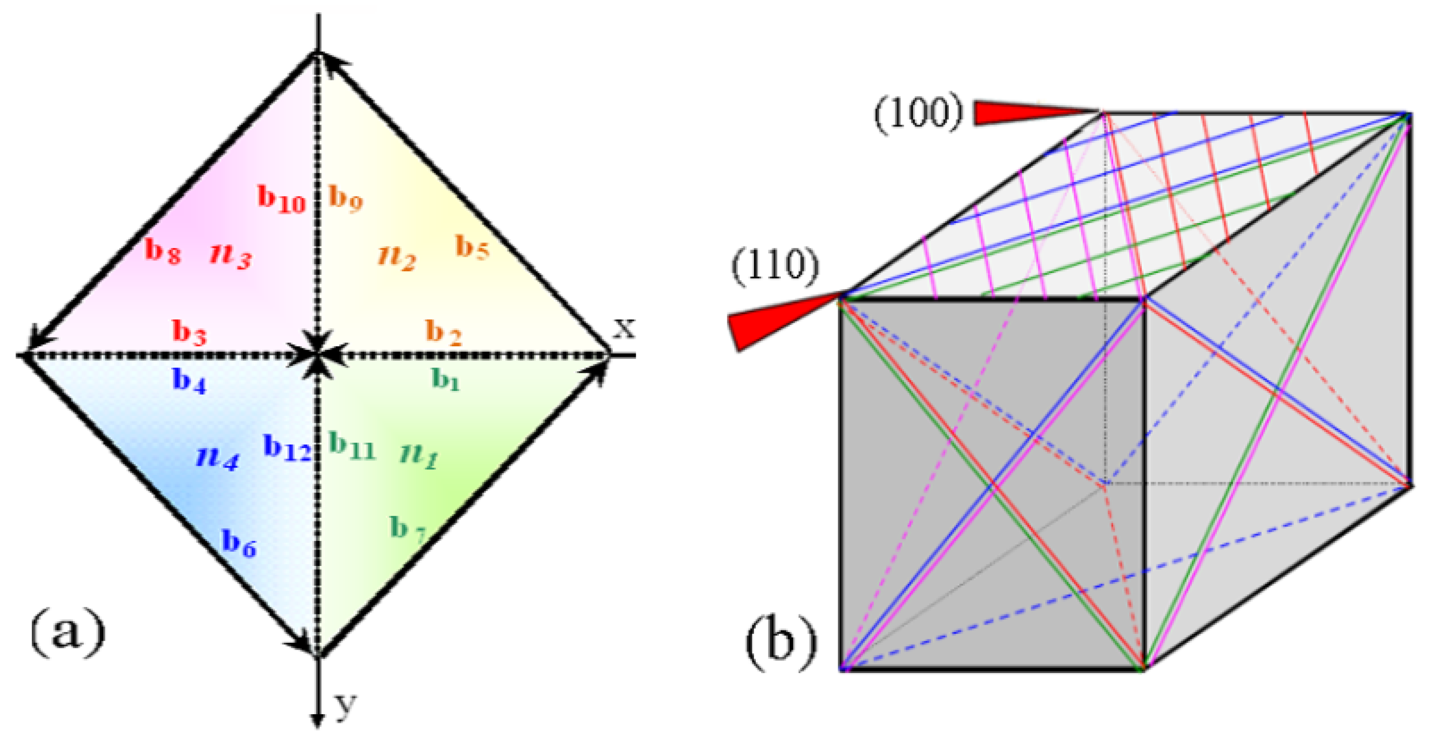
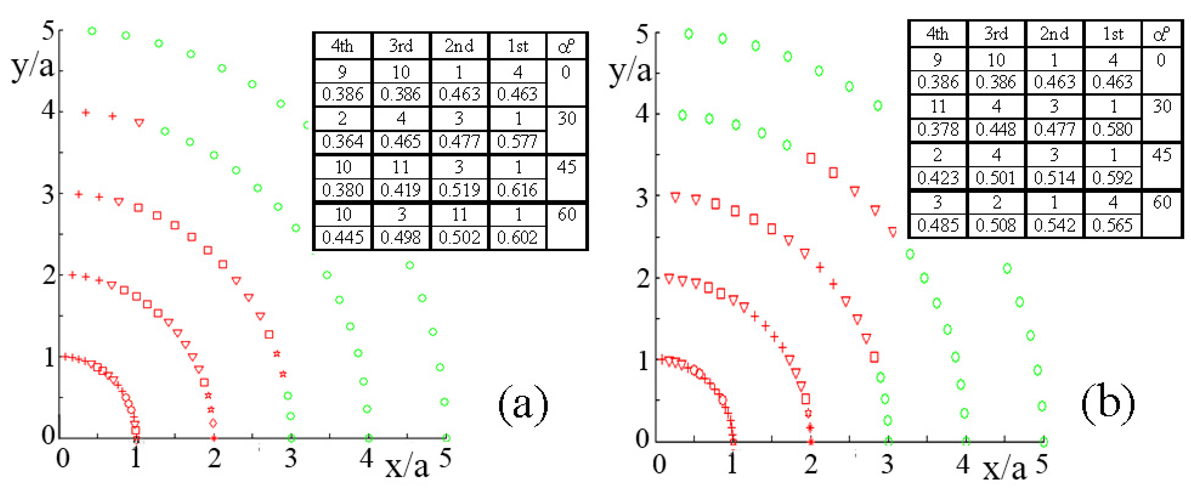
- How are the slip systems selected, for each crystallographic orientation of the specimen or the grain, relative to the external load?
- (b)
- To what extent does the crystallographic orientation contribute to the variability of the crack growth rate of SFCs?
- (c)
- How does the crack growth threshold, (ΔKI)th, in monocrystals depends on the crystallographic orientation?
2. Materials and Methods
3. Results
4. Discussion
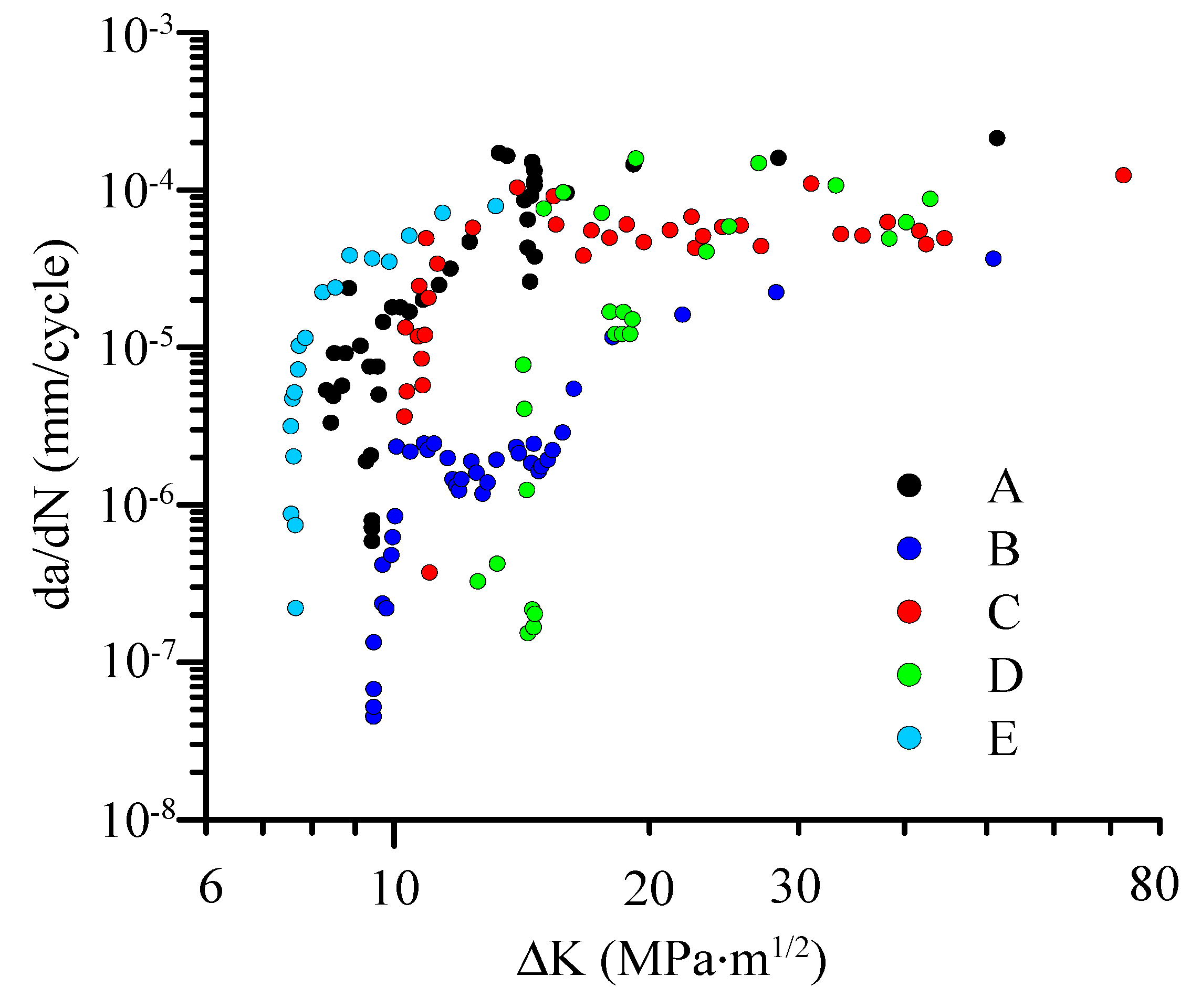
- The long fatigue cracks in the nickel monocrystal exhibit lower threshold values (ΔKI)th than in polycrystalline nickel, similarly to short fatigue cracks in a polycrystalline material.
- The fatigue crack growth rate (FCGR) of a long crack in monocrystalline nickel at low values of ΔKI was found to be higher than in the corresponding section of the FCGR curve in polycrystalline nickel. This replicates the well-known behavior of short fatigue cracks in polycrystalline metals.
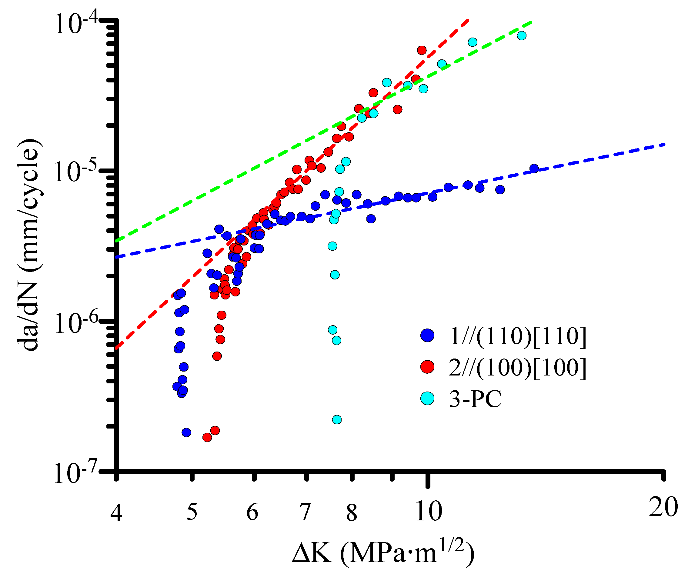
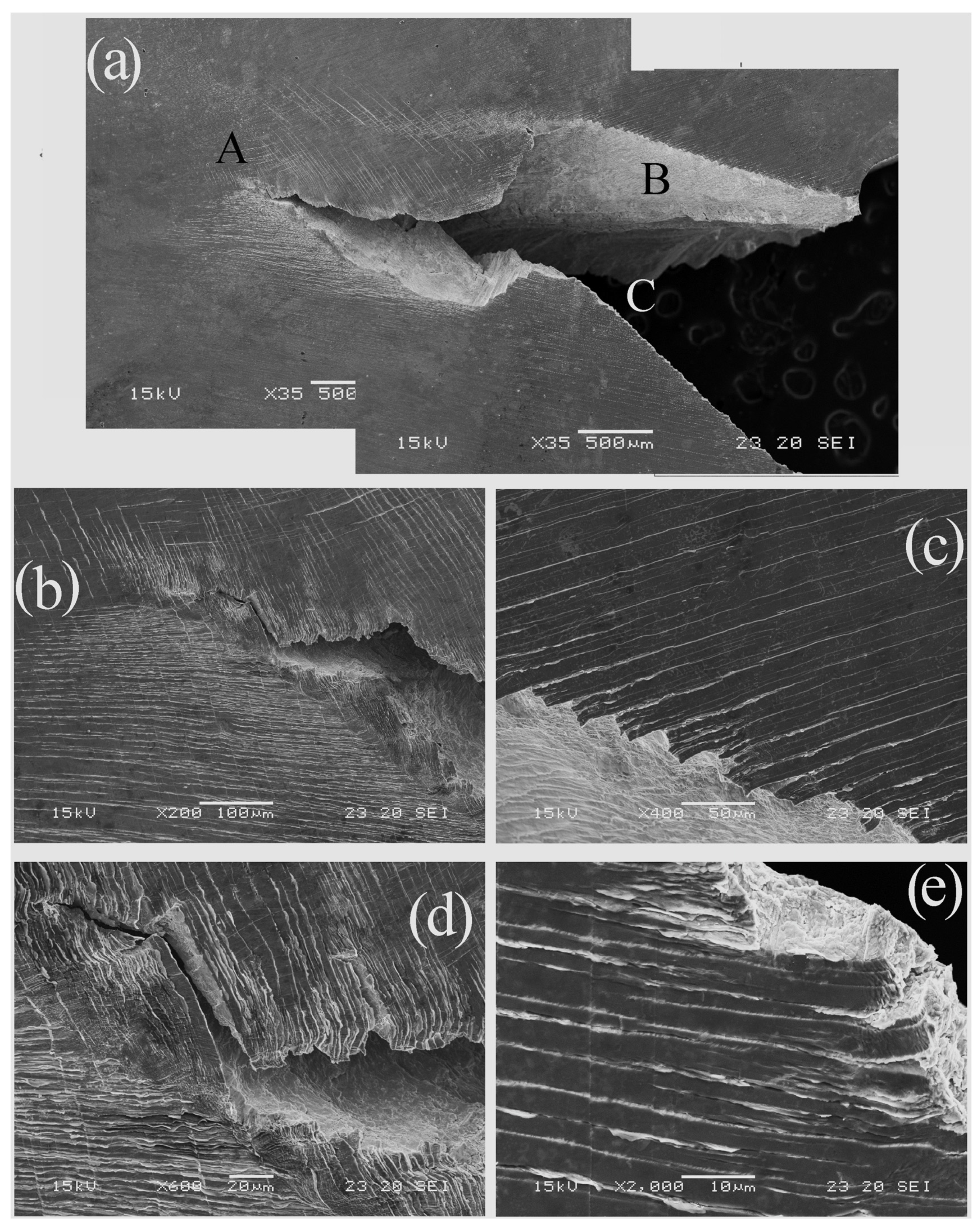
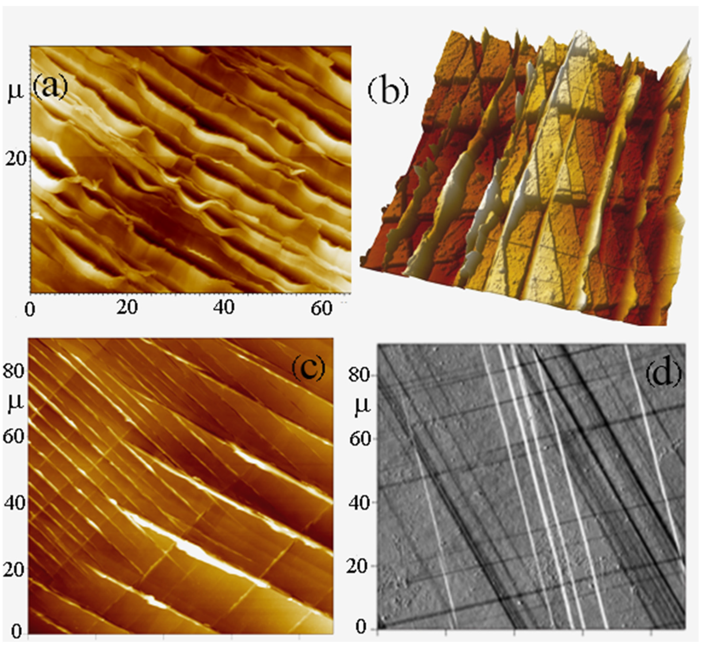
- The crack path in the {110} plane (Figure 10) is characterized by roughness and deflections. The P-COD loop, not presented, indicates the existence of significant crack closure resulting from the high level of fracture roughness. They reduce the crack driving force and hence the effective stress intensity factor amplitude, ΔKIeff, giving rise to a slower crack growth rate and a relatively flat Paris slope (n = 1.1) (Figure 4).
- The present results are in accordance with other observations, e.g., Chan et al. [16] who performed fatigue tests on a monocrystal of Mar-M200 with different crystallographic orientations. According to Xiaoyi et al. [23], orientations close to (110) activate two competing slip systems, and the path of the growing fatigue crack deflects and branches. These extrinsic phenomena reduce the fatigue crack growth rate and increase the total fatigue life. On the other hand, orientations close to (100) activate mainly planar slip. The FCGR is higher since no extrinsic sources are being activated, which could have delayed crack extension.
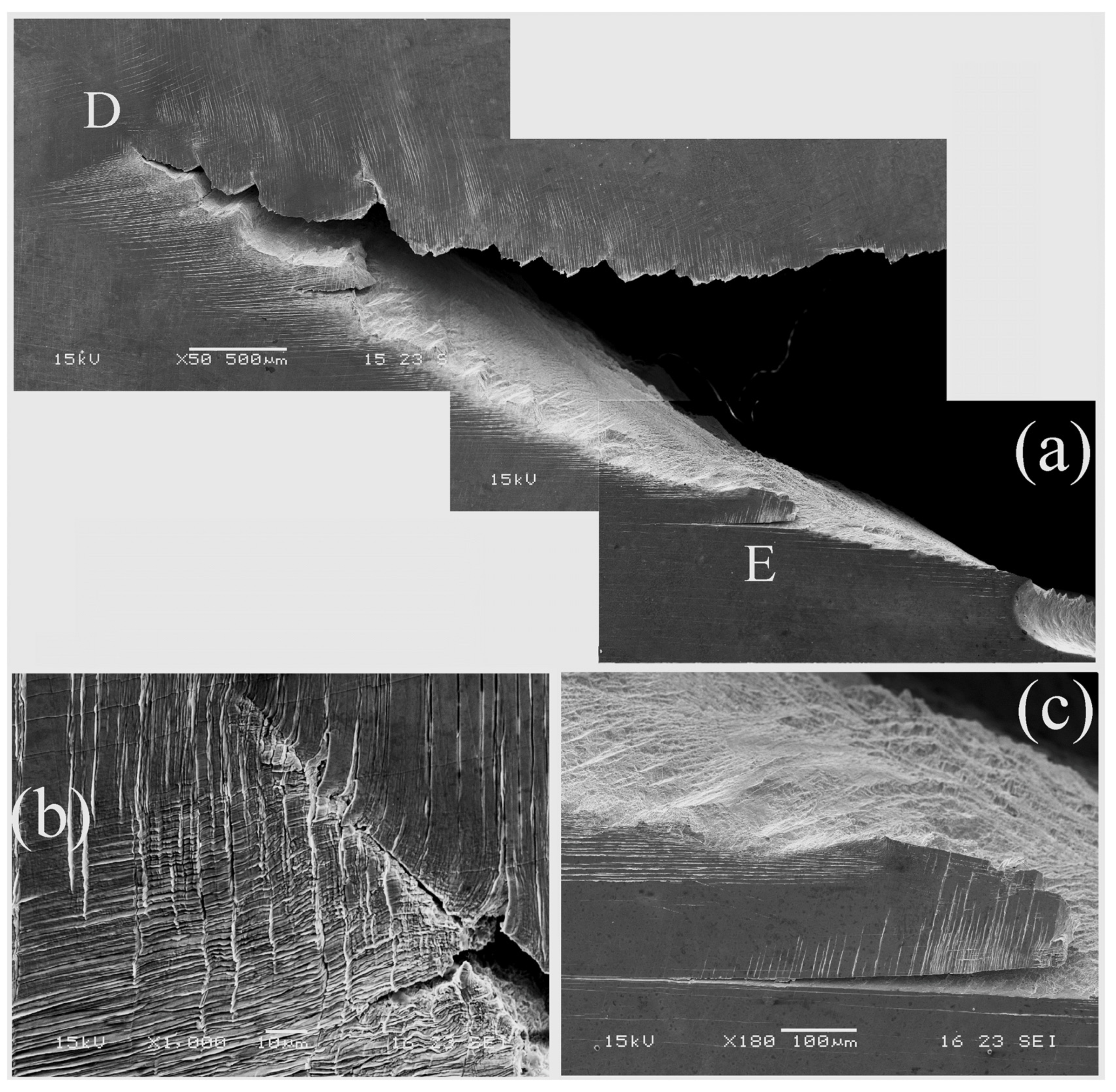
- Different slip planes are dominant above the crack plane and below it. This selection rule probably reduces the strain hardening during crack growth.
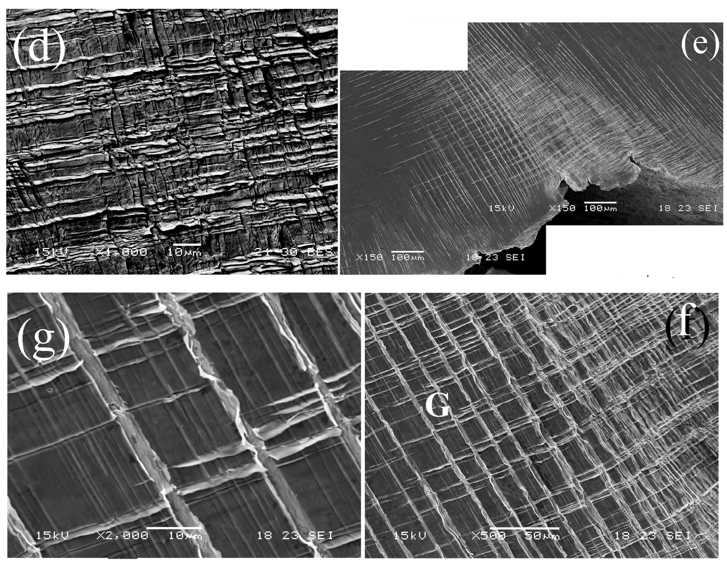
- A new slip system (none {111}) is occasionally activated whenever intensive slip is required.
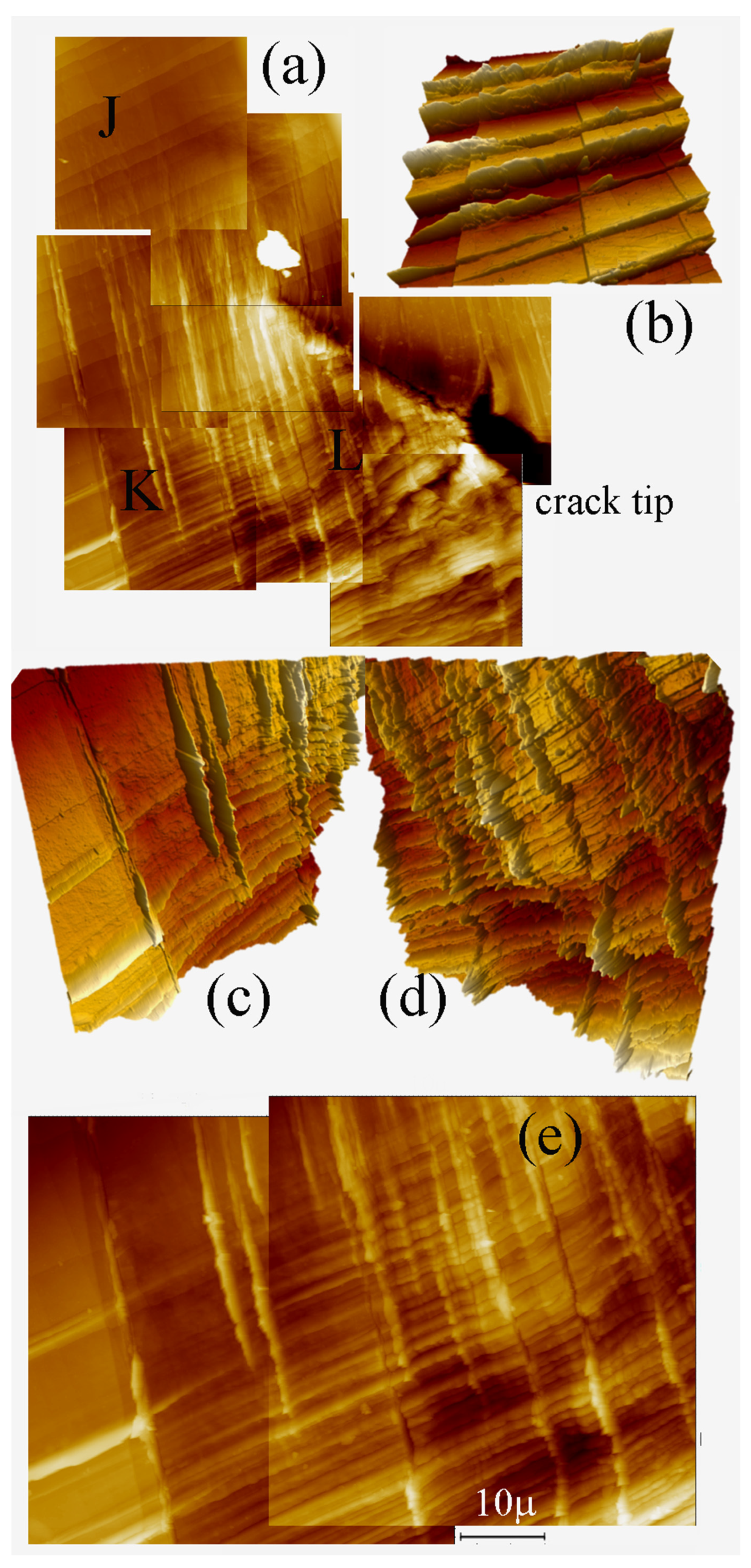
- In regions of high stress intensity factors, namely close to the crack-tip, and as crack length increases, the slip intensity increases by activation of dense slip. The intense shear gradually fades by reducing both the height and the density of the active slip planes.
5. Conclusions
- (a)
- Different cracks exhibit different FCGR behavior.
- (b)
- The FCGR at low ΔK of a long crack in a monocrystal is higher than the corresponding part of the FCGR curve of a polycrystal.
- (c)
- Long fatigue cracks in a monocrystal exhibit lower threshold ΔKth. values.
- (a)
- Different slip planes are dominant above and below the crack plane. This selection rule apparently reduces the strain hardening during crack growth.
- (b)
- A new slip system (none {111}) is occasionally activated whenever intensive slip is required.
- (c)
- In regions of high stress intensity factors, namely close to the crack tip and with increasing crack length, the slip intensity increases by the activation of dense slip planes. The intense shear gradually fades by reducing both the height and the density of the slip steps.
Author Contributions
Funding
Institutional Review Board Statement
Informed Consent Statement
Data Availability Statement
Acknowledgments
Conflicts of Interest
References
- Paris, P.C.; Gomez, P.M.; Anderson, W.E. A rational analytic theory of fatigue. Trend Eng. 1961, 13, 9–14. [Google Scholar]
- Suresh, S. Fatigue of Materials; Cambridge University Press: Cambridge, UK, 1998. [Google Scholar]
- Ritchie, R.O.; Lankford, J. Small fatigue cracks: A statement of the problem and potential solutions. Mater. Sci. Eng. 1986, 84, 11–16. [Google Scholar] [CrossRef]
- Ritchie, R.O.; Suresh, S. The fracture mechanics similitude concept: Questions concerning application to the behavior of short fatigue cracks. Mater. Sci. Eng. 1983, 57, L27–L30. [Google Scholar] [CrossRef]
- McClung, R.C.; Chan, K.S.; Hudak, J.S.J.; Davidson, D.L. Behavior of Small Fatigue Cracks. Fatigue and Fracture. In ASM Handbook; ASM International: Novelty, OH, USA, 1996; Volume 19, pp. 372–386. [Google Scholar]
- Okazaki, M.; Yamada, H.; Nohmi, S. Temperature dependence of the intrinsic fatigue crack growth behavior in Ni-base superalloys based on measurement of crack closure. Metall. Mater. Trans. 1996, 27A, 1221–1231. [Google Scholar] [CrossRef]
- Zhang, X.P.; Wang, C.H.; Ye, L.; Mai, Y.W. In situ investigation of small fatigue crack growth in poly-crystal and single-crystal aluminum alloys. Fatigue Fract. Eng. Mater. Struct. 2002, 25, 141–150. [Google Scholar] [CrossRef]
- Nalla, R.K.; Campbell, J.P.; Ritchie, R.O. Effects of microstructure on mixed mode HCF crack growth thresholds in T—6Al-4V alloy. Fatigue Fracture Engin. Mater. Struct. 2002, 25, 587–606. [Google Scholar] [CrossRef]
- Peralta, P.; Dickerson, R.; Dellan, N.; Komandur, K.; Jameel, M.A. Effects of Local Grain Orientation on Fatigue Crack Growth in Multicrystalline FCC Metallic Materials. ASME J. Eng. Mater. Technol. 2005, 127, 23–32. [Google Scholar] [CrossRef]
- Krupp, U.; Duber, O.; Christa, H.-J.; Kunkler, B.; Koster, P.; Fritzen, C.-P. Propagation mechanisms of microstructurally short cracks—Factors governing the transition from short- to long-crack behavior. Mater. Sci. Eng. A 2007, 462, 174–177. [Google Scholar] [CrossRef]
- Simonovski, I.; Cizelj, L. The influence of grains’ crystallographic orientations on advancing short crack. Int. J. Fatigue 2007, 29, 2005–2014. [Google Scholar] [CrossRef]
- Blochwitz, C.; Jacob, S.; Tirschler, W. Grain orientation effects on the growth of short fatigue cracks in austenitic stainless steel. Mater. Sci.Eng. A 2008, 496, 59–66. [Google Scholar] [CrossRef]
- Dueber, O.; Knobbe, H.; Fritzen, C.P.; Kuenkler, B.; Koester, P.; Krupp, U.; Christ, H.-J. Propagation behavior of microstructural short fatigue cracks-experimental characterization and mechanism-based simulation. Mater. Werkst. 2008, 39, 688–693. [Google Scholar]
- Christ, H.-J.; Duber, O.; Fritzen, C.-P.; Knobbe, H.; Koster, P.; Krupp, U.; Kunkler, B. Propagation behaviour of microstructural short fatigue cracks in the high-cycle fatigue regime. Comput. Mater. Sci. 2009, 46, 561–565. [Google Scholar] [CrossRef]
- Schaef, W.; Marx, M.; Vehoff, H.; Heckl, A.; Randelzhofer, P. A 3-D view on the mechanisms of short fatigue cracks interacting with grain boundaries. Acta Mater. 2011, 59, 1849–1861. [Google Scholar] [CrossRef]
- Chan, K.S.; Hack, J.E.; Leverant, G.R. Fatigue crack growth in MAR-M200 monocrystals. Metall. Mater. Trans. A 1987, 18, 581–591. [Google Scholar] [CrossRef]
- Defresne, A.; Remy, L. Fatigue behavior of CMSX 2 superalloy [001] single crystals at high temperature: Fatigue crack growth. Mater. Sci. Eng. 1990, 129A, 55–64. [Google Scholar] [CrossRef]
- Zhang, Y.; Qiu, W.; Shi, H.-J.; Li, C.; Kadau, K.; Luesebrink, O. Effects of secondary orientations on long fatigue crack growth in a monocrystal superalloy. Eng. Fract.Mech. 2015, 136, 172–184. [Google Scholar]
- Reed, P.A.S.; Wu, X.D.; Sinclair, I. Fatigue Crack Path Prediction in UDIMET 720 Nickel-Based Alloy Monocrystals. Metall. Mater. Trans. 2000, 31A, 109–123. [Google Scholar] [CrossRef]
- Lerch, B.A.; Antolovich, S.D. Fatigue crack propagation behavior of a single crystalline superalloy. Metall. Mater. Trans. 1990, 21A, 2169–2177. [Google Scholar] [CrossRef]
- Aswath, P.B. effect of orientation on crystallographic cracking in notched nickel base superalloy monocrystal subjected to far field cyclic compression. Metall. Mater. Trans. 1994, 25A, 287–297. [Google Scholar] [CrossRef]
- Magnan, S. Three Dimensional Stress Fields and Slip Systems for Monocrystal Superalloy Notched Specimens. Master’s Thesis, University of California, Oakland, CA, USA, 2002. [Google Scholar]
- Xiaoyi, R.; Junxia, L.; Jianli, Z.; Xianqiang, L.; Wenxiang, J.; Jin, W.; Yuefei, Z.; Ze, Z. In-situ fatigue behavior study of a nickel-based single-crystal super-alloy with different orientations. Mater. Sci.Eng. A 2022, 855, 143913. [Google Scholar]
- Zehnder, A.T. Fracture Mechanics; Springer: Dordrecht, The Netherlands, 2012. [Google Scholar]
- Polak, J.; Kruml, T.; Obrtlik, K.; Man, J.; Petrence, M. Short crack growth in polycrystalline material. Procedia Eng. 2010, 2, 883–892. [Google Scholar] [CrossRef]


Disclaimer/Publisher’s Note: The statements, opinions and data contained in all publications are solely those of the individual author(s) and contributor(s) and not of MDPI and/or the editor(s). MDPI and/or the editor(s) disclaim responsibility for any injury to people or property resulting from any ideas, methods, instructions or products referred to in the content. |
© 2023 by the authors. Licensee MDPI, Basel, Switzerland. This article is an open access article distributed under the terms and conditions of the Creative Commons Attribution (CC BY) license (https://creativecommons.org/licenses/by/4.0/).
Share and Cite
Petel, A.; Jager, A.; Babai, D.; Jopp, J.; Bussiba, A.; Perl, M.; Shneck, R.Z. Fatigue Crack Growth in a Monocrystal and Its Similarity to Short-Crack Propagation in a Polycrystal of Nickel. Metals 2023, 13, 790. https://doi.org/10.3390/met13040790
Petel A, Jager A, Babai D, Jopp J, Bussiba A, Perl M, Shneck RZ. Fatigue Crack Growth in a Monocrystal and Its Similarity to Short-Crack Propagation in a Polycrystal of Nickel. Metals. 2023; 13(4):790. https://doi.org/10.3390/met13040790
Chicago/Turabian StylePetel, Avihai, Ales Jager, Dotan Babai, Juergen Jopp, Arie Bussiba, Mordechai Perl, and Roni Z. Shneck. 2023. "Fatigue Crack Growth in a Monocrystal and Its Similarity to Short-Crack Propagation in a Polycrystal of Nickel" Metals 13, no. 4: 790. https://doi.org/10.3390/met13040790