
In-Situ Observation of Steel/Slag/Inclusion Interaction by Means of High-Temperature Confocal Scanning Laser Microscopy


Christian Doppler Laboratory for Inclusion Metallurgy in Advanced Steelmaking, Montanuniversitaet Leoben, 8700 Leoben, Austria
*
Author to whom correspondence should be addressed.
Metals 2023, 13(4), 686; https://doi.org/10.3390/met13040686
Submission received: 9 March 2023
/
Revised: 28 March 2023
/
Accepted: 28 March 2023
/
Published: 30 March 2023
(This article belongs to the Special Issue Advanced Tundish Metallurgy and Clean Steel Technology)
Abstract
:Non-metallic inclusions (NMIs) in steels have been the focus of various experimental studies due to their detrimental character. While isolated processes, such as agglomeration or dissolution, have been well investigated, holistic in-situ views with high-temperature confocal scanning laser microscopy (HT-CSLM) have been rare. In this work a novel and suitable method is presented to simultaneously observe agglomeration, movement, detachment, and dissolution of non-metallic inclusions by combined the melting of steel and slag with a dual-crucible approach. Therefore, different steel/slag combinations were tested. It is shown that, with transparent that does not become tarnished by the ions stemming from the steel, the steel’s surface and non-metallic inclusions are observable. Furthermore, technological limitations are discussed, including restrictions regarding the melting point of steels and certain steel/slag combinations.
1. Introduction
In steelmaking, heterogeneous reactions at different interfaces commonly occur, such as oxidizing and flushing between steel melt and gas bubbles and carburizing between steel melt and solid coke [1]. The interfacial reactions between steel and slag play a crucial role, especially in secondary metallurgy [2]. Slag not only acts as an interlayer barrier with the atmosphere, thus limiting oxygen and nitrogen pickup, but it also picks up desulfurization and deoxidation products [3]. These deoxidation products mostly consist of aluminum and silicon oxides and their mixes. Since these reaction products cannot be completely transferred to the slag, they partially remain in steel and solidify as non-metallic inclusions, which can be detrimental for various material properties, especially fatigue [4,5,6]. Other inclusions, such as sulfides and nitrides precipitate from steel during cooling and solidification due to exceeding the solubility limits. Furthermore, inclusions can originate from preexisting inclusions in alloying materials, entrapped slag, or refractories [7,8].
Chemical reactions, including steel and slag, as well as the absorption of non-metallic inclusions by slag, have often been investigated ex situ by metallographic means after experiments in crucibles in different furnaces [9,10,11] or in situ via the X-ray sessile drop method [2]. These methods allow only macroscopic observations, excluding non-metallic inclusions in most cases. Furthermore, the behavior of non-metallic inclusions in steel melt and at the steel/slag interface has been numerically modelled [12,13]. One outstanding device for in-situ investigation of microscopic processes is high-temperature confocal scanning laser microscopy (HT-CSLM). The technique of scanning lasers is not only used for analytical purposes but also for industrial applications, such as fusion of metal powders [14]. With HT-CSLM, a great variety of investigations at elevated temperatures are possible, including different phase transformations of steels and slags of different solid states or solid/liquid transformations [15,16]. Thanks to the high heating and cooling rates achievable with this furnace, the investigation of non-equilibrium transformations, such as the formation of bainite or martensite, is possible as well [17,18]. With HT-CSLM, different steel cleanness-relevant processes are investigable, including agglomeration of non-metallic inclusions at liquid steel surfaces [19,20] and modification of non-metallic inclusions at the steel/slag interface [21]. In particular, the dissolution of different oxidic particles in molten slags has been well investigated with this tool. The observation of the reduction in the radii during the course of experiments allows for the distinction between diffusive and kinetically controlled diffusion mechanisms. Thus, the calculation of either the effective diffusion coefficients or the investigation of potentially formed reaction layers is possible [22,23,24,25].
Until today, these non-metallic inclusion-involving experiments were stand-alone research, and holistic studies of the agglomeration of particles, their movement from the steel to the steel/slag interface, their detachment to the slag phase, and their dissolution into the slag phase have not been performed to any great extent. With combined investigation, different challenges occur, such as achieving a transparent slag throughout the experiment to ensure the detection and tracking of inclusions in it. Therefore, this communication addresses the behavior of non-metallic inclusions throughout secondary metallurgical processes by studying the interfaces of steel/slag and steel/slag/argon with the help of HT-CSLM. The used and described experimental set-up represents a novel way to investigate various metallurgical reactions coupled and in-situ with a microscopic view. This set-up, in combination with the steel-slag system used, enables the tracking of non-metallic inclusions while eliminating any risk to the equipment (e.g., leaking).
2. Materials and Methods
To achieve observability of the processes occurring, slags that are transparent at the wavelength of the 405-nm HT-CLSM laser (Yonekura Manufacturing Co., Ltd., Yokohama, Japan) have to be utilized [26]. The synthetic slag in these investigations is comparable to the low alumina pseudo-wollastonitic slags used for ultra-clean steels in secondary metallurgy. There was the extra addition of lithium oxide into the slag to greatly lower the melting point and viscosity. The slag was prepared by mixing pure oxide powders of CaO, SiO2, and Al2O3. Li2O was introduced by adding Li2CO3, which decomposes at elevated temperatures into lithium oxide and carbon dioxide. All slag components were purchased from Sigma-Aldrich (St. Louis, MO, USA). The mixture was then melted in a platinum crucible and kept at 1600 °C for 30 min using a resistance-heated laboratory-scale furnace to be homogenized. The melted mixture was then quenched by pouring it into a metal mold to obtain a glassy structure and was subsequently crushed to be able to dose the chunks well. The slag compositions, as seen in Table 1, were measured by XRF analysis for CaO, SiO2, and Al2O3 and by ICP-OES for alkali oxides. The error of measurement of these chemical analyses was the usual deviation of XRF and ICP-OES. Additionally, trials with sodium oxide-bearing slags were conducted. Unlike lithium, this oxide enables EDS measurements using an SEM with a beryllium window. Unfortunately, sodium oxide tends to vaporize and deposit on the golden wall of the HT-CSLM, leading to reduced heating by radiation and preventing the reaching of the melting range of the used steel. Therefore, the results shown were obtained using sodium-containing slag.
The main requirement of the steel is the absence of transition metals, as they would tarnish the slag if their ions dissolved into it. Furthermore, the melting range of the steel should be significantly lower than pure iron. To obtain this range, a steel melt with the composition shown in Table 2 was produced by high-frequency remelting of pure iron, broken silicon chunks, high purity aluminum wire, and a 4.4 wt.% C iron-pre-alloy in an alumina crucible without the addition of any slag. The melting procedure with a Lifumat-Met-3,3-vac high-frequency remelting (HFR) furnace (Linn High Therm GmbH, Eschenfelden, Germany), with a spin caster unit was already reported in Thiele et al. [27]. This melt was then poured in a copper mold and analyzed afterward by SPECTROMAXx optical emissions spectrometry (OES, SPECTRO Analytical Instruments GmbH, Kleve, Germany). The error of measurement of this chemical analysis is the usual deviation of OES. Carbon was added via the iron-pre-alloy to lower the melting point of the steel sample compared to the ultra-low carbon steel (ULC) crucible, while aluminum acts as a deoxidizer to obtained mostly stable Al2O3 inclusions.
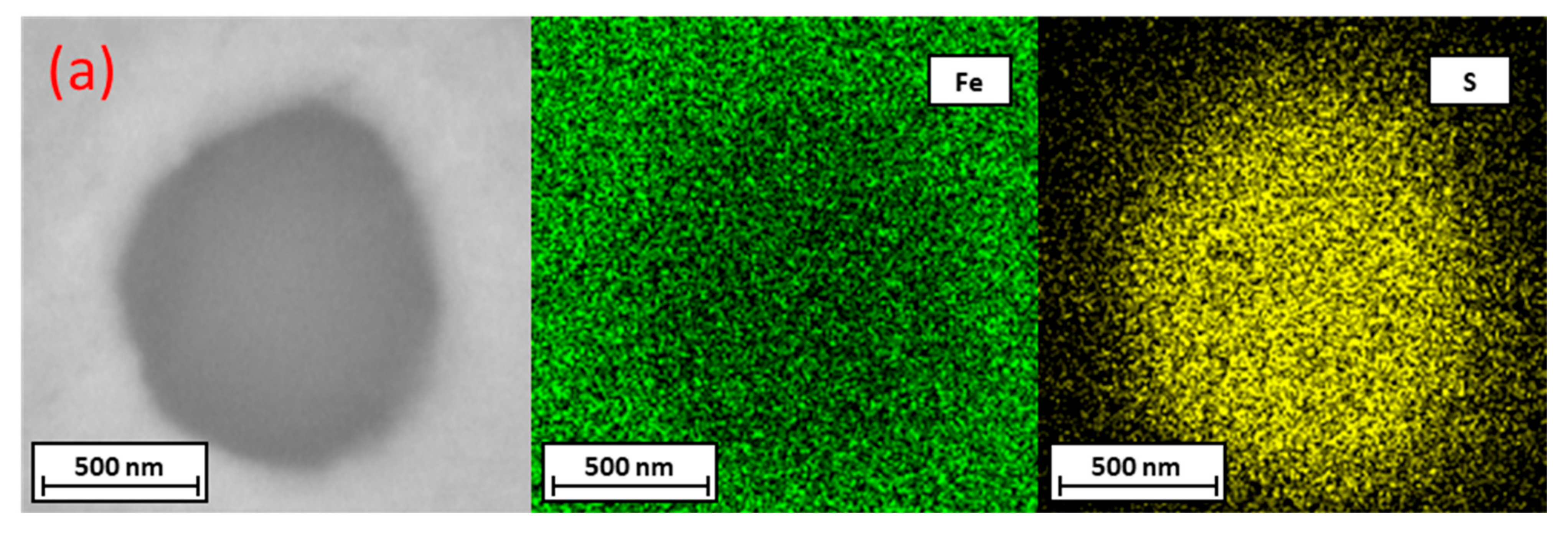
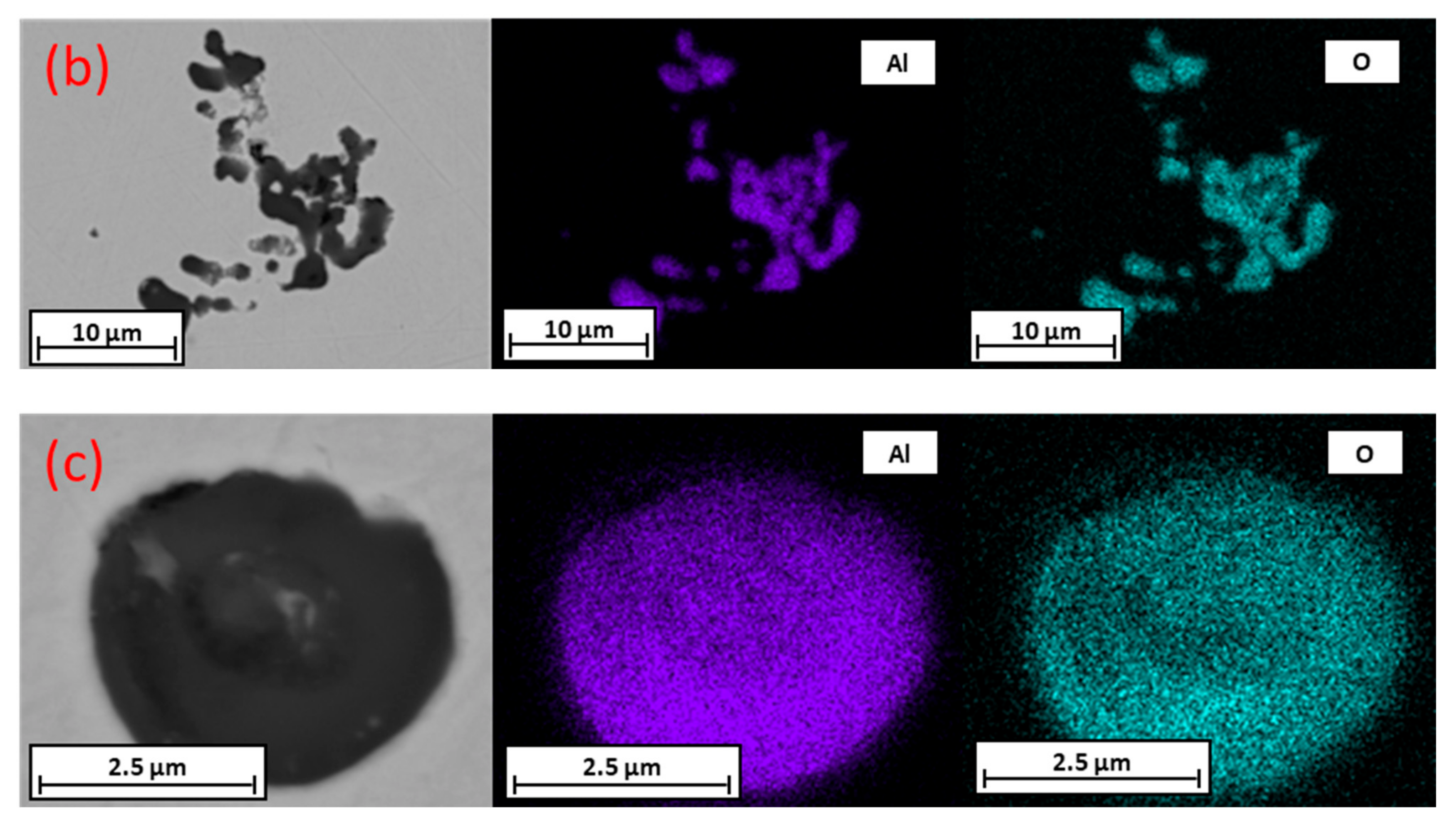
For inclusion analytics, the JEOL 7200F (JEOL Ltd., Akishima, Japan) scanning electron microscope (SEM) with Oxford Instruments’ Aztec 6.0 (Oxford Instruments, Abingdon, UK) software was used. For the analysis of the crucible post-experiment, a FEI Quanta M200 (FEI Company, Hillsboro, OR, USA) SEM was used due to its ability to investigate oxidic non-conductive substances in its low vacuum mode. The automated scanning electron microscope with energy dispersive spectrometry (SEM/EDS) analysis of the steel sample showed 132 inclusions per mm2 with an average equivalent circular diameter (ECD) of 2.41 µm. Of the 5410 inclusions found, 4160 were oxidic and were mainly Al2O3. Furthermore, 646 sulfides and 604 oxide-sulfides were found with iron as the bonding partner of sulfur. Since FeS decomposes at elevated temperatures before the melting of steel, only alumina inclusions could be observed with the experiments using HT-CSLM. Elemental mappings and backscattered electron (BSE) images of representative inclusions for FeS (Figure 1a), an alumina cluster (Figure 1b), and a single Al2O3 inclusion (Figure 1c) can be seen. Before the HT-CSLM experiments, steel sample plates were cut to dimensions of 3.5 × 3.5 × 1.5 mm, embedded, ground, and polished to achieve a flat surface for good focusing capability, and oxides that could tarnish the slag were removed. To avoid reoxidation the plates were then broken out of the embedding mass and stored in ethanol until usage.
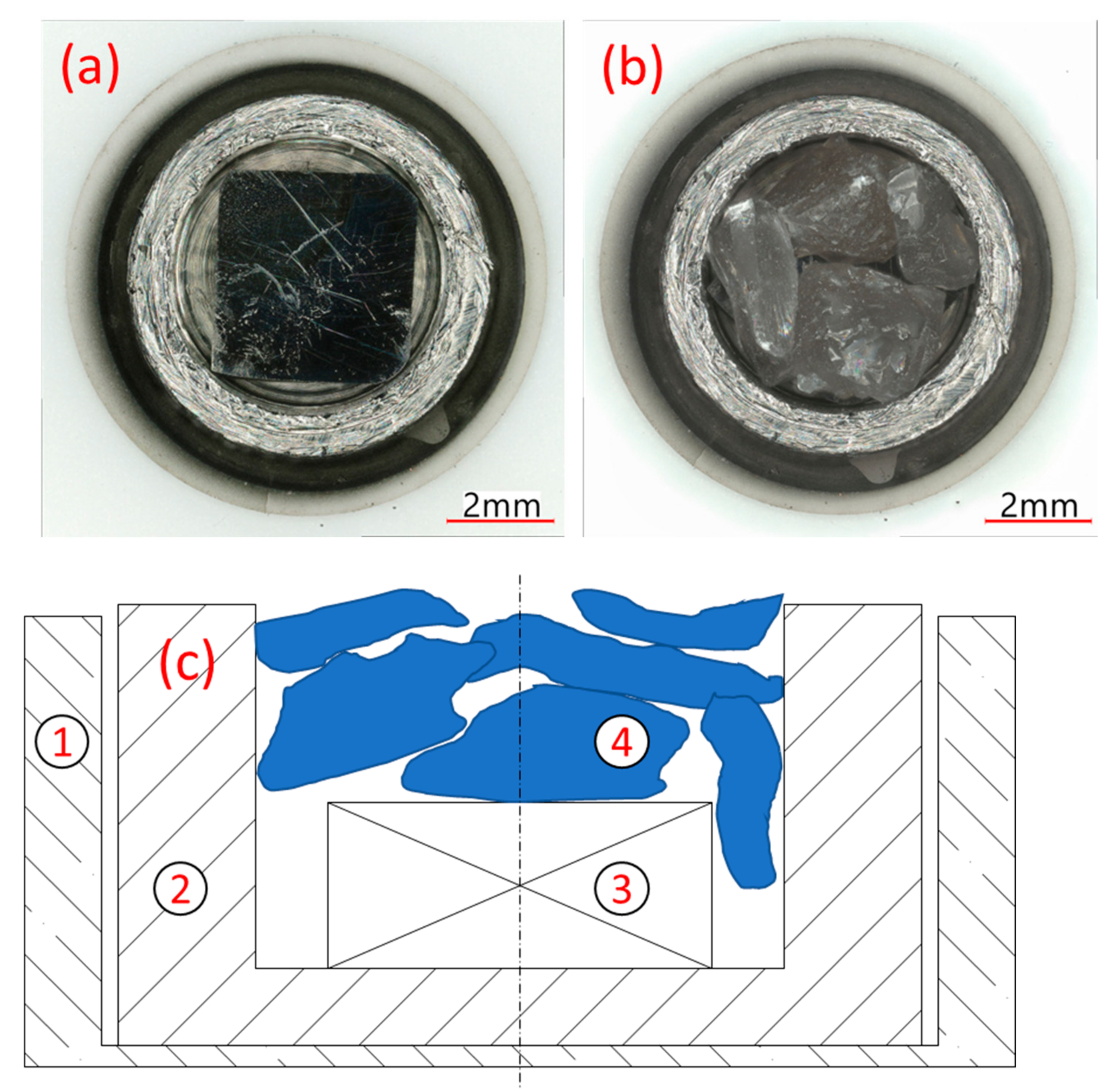
The steel plate, with a mass of around 0.12 g, was inserted into the ULC crucible with a mean mass of 0.76 g and covered with approximately 0.07 g of glassy slag chunks. The filled ULC crucible was placed in an alumina crucible (Yonekura Manufacturing Co., Ltd., Yokohama, Japan). This set-up is shown in Figure 2 with (Figure 2a) and without (Figure 2b) slag and also schematically in Figure 2c. This set-up ensures that the slag is only in contact with the steel specimen and the ULC crucible and thus prevents potential slag leakage into the furnace chamber, which would cause severe damage to the HT-CLSM. The HT-CLSM provides precise control over the melting of specimens so they do not melt entirely. The melting ranges of all used materials and crucibles did not overlap. According to FactSageTM 8.0 with the FToxid database, the liquidus temperature of the slag was 1211 °C. The melting range of the investigated steel is between 1375 and 1476 °C, the ULC crucible melts at 1536 °C—calculated with Fsstel—and the melting point of the alumina crucible is far greater. The difference in melting points of ULC and steel specimens and a small melt pool guarantees very limited interaction between these two. In case of leaking of the ULC crucible, the alumina crucible acts as barrier to catch liquids that would cause severe damage to the device. This barrier has enough volume to catch slag and both steels. In this case, the operator has enough time to shut down the heating source and quench the specimen with the HT-CSLM’s high cooling rate of up to 1200 K/min before the slag can dissolve the alumina.
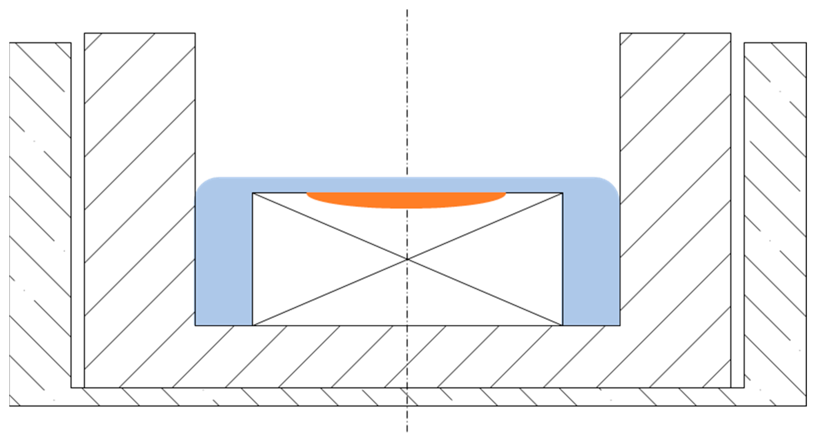
For the experiments, the type VL2000DX confocal scanning laser microscope (Lasertec Corporation, Yokohama, Japan), combined with a type SVF17-SP high-temperature furnace from (Yonekura Manufacturing Co., Ltd., Yokohama, Japan), was used (HT-CSLM). This set-up has been described earlier in detail [15]. The furnace atmosphere was argon 5.0, which was additionally passed through a titanium-obtaining furnace to reduce the amount of remaining oxygen even further. Prior to every experiment, the furnace was flushed three times, followed by evacuation with a vacuum pump. This step is crucial to remove residual oxygen from the atmosphere, which could lead to immediate scale formation on the steel plate and the ULC crucible; the iron oxides from the scales would have led to tarnishing of the slag, which would thereby impede the observability of steel through the slag. This atmosphere evacuation step was finished after reaching an oxygen level of less than 2 ppm as measured by the Rapidox 2100 Oxygen Analyser (Cambridge Sensotec Limited, Cambridge, UK). High heating rates of 600 K/min till 1300 °C and 100 K/min till 1350 °C and subsequential manual increases by up to 10 K/min were used until melting of the steel in the HT-CSLM occurred. This set-up with partly molten steel covered by liquid slag is shown in Figure 3. With this gradual temperature rise, partial melting of the steel sample plate is achieved to control the number of inclusions released into the steel melt and keep the pool of molten steel small. With this process, inclusions can be tracked as they reach the steel’s surface until they dissolve into the slag. Furthermore, the steel/slag interface with incomplete covering of the steel/slag/argon interface can be investigated. Rapid cooling rates of up to 1000 K/min were used to freeze the processes for subsequent metallographic examination.
3. Results
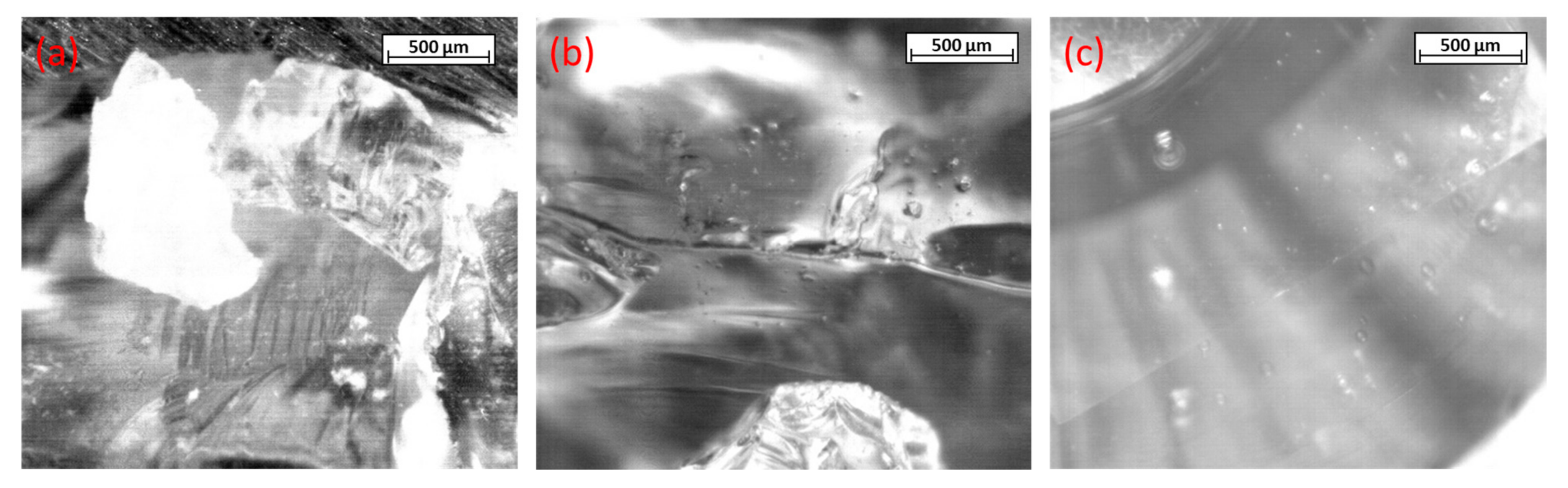
The first step was to obtain sufficient visuals of the steel plate through the molten slag. While heating, the glassy chunks of the slag first softened (Figure 4a) and started to melt (Figure 4b). Due to the slag’s surface tension, the plate was not fully submerged. The contours of the solid plate, which were covered by liquid slag, were observable through the liquid slag, as can be seen in Figure 4c with sufficient clarity. The majority of gas bubbles were removed while holding at temperatures between the slag’s and steel´s melting points.
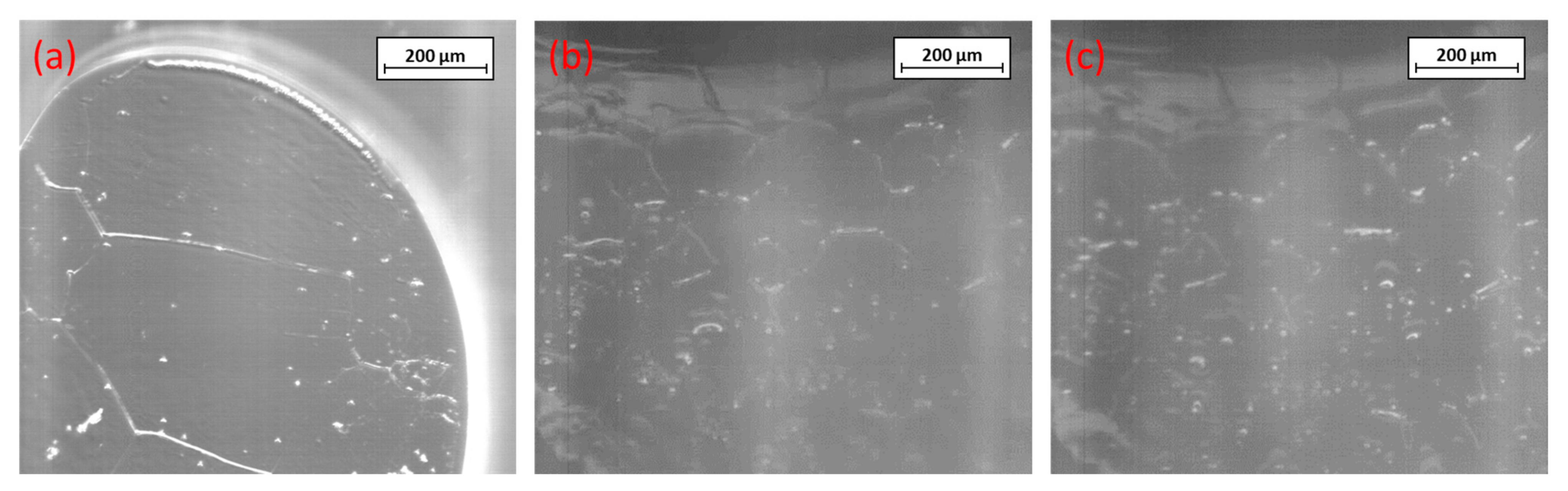
With a further increase in the temperature, thermal etching of the steel plate occurred, and later partial melting of the plate can be observed starting at grain boundaries, as well as at the steel/slag/gas interface, as seen in Figure 5a. Although the slag became more opaque with time, the melting of the plate was also observable through the slag, which can be seen in Figure 5b,c. Even after 30 min, the transparency of the slag remained sufficient to observe the steel pool´s surface. The contrast and brightness of the pictures were increased in these two images for better visibility.
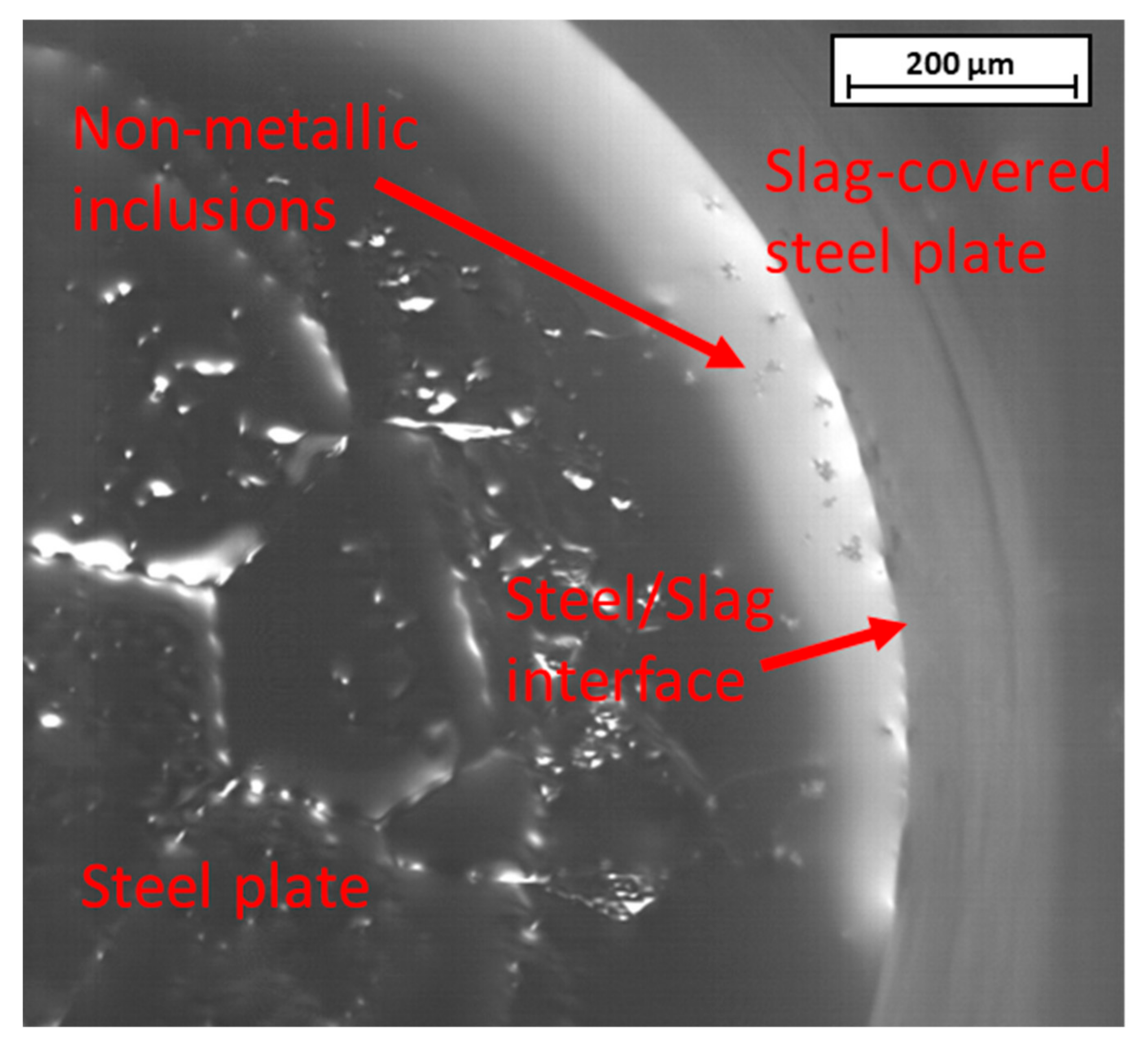
The interface between partly molten steel and liquid slag is the focus of Figure 6, in which the three-phase border steel-slag-atmosphere is clearly visible. Furthermore, in this figure, first inclusions, as well as their agglomerates, can be seen in the steel phase near the steel/slag interface. Their reflection appears in the slag phase due to arching of the slag above the steel plate because of wetting phenomena.
3.1. Observability of Inclusions
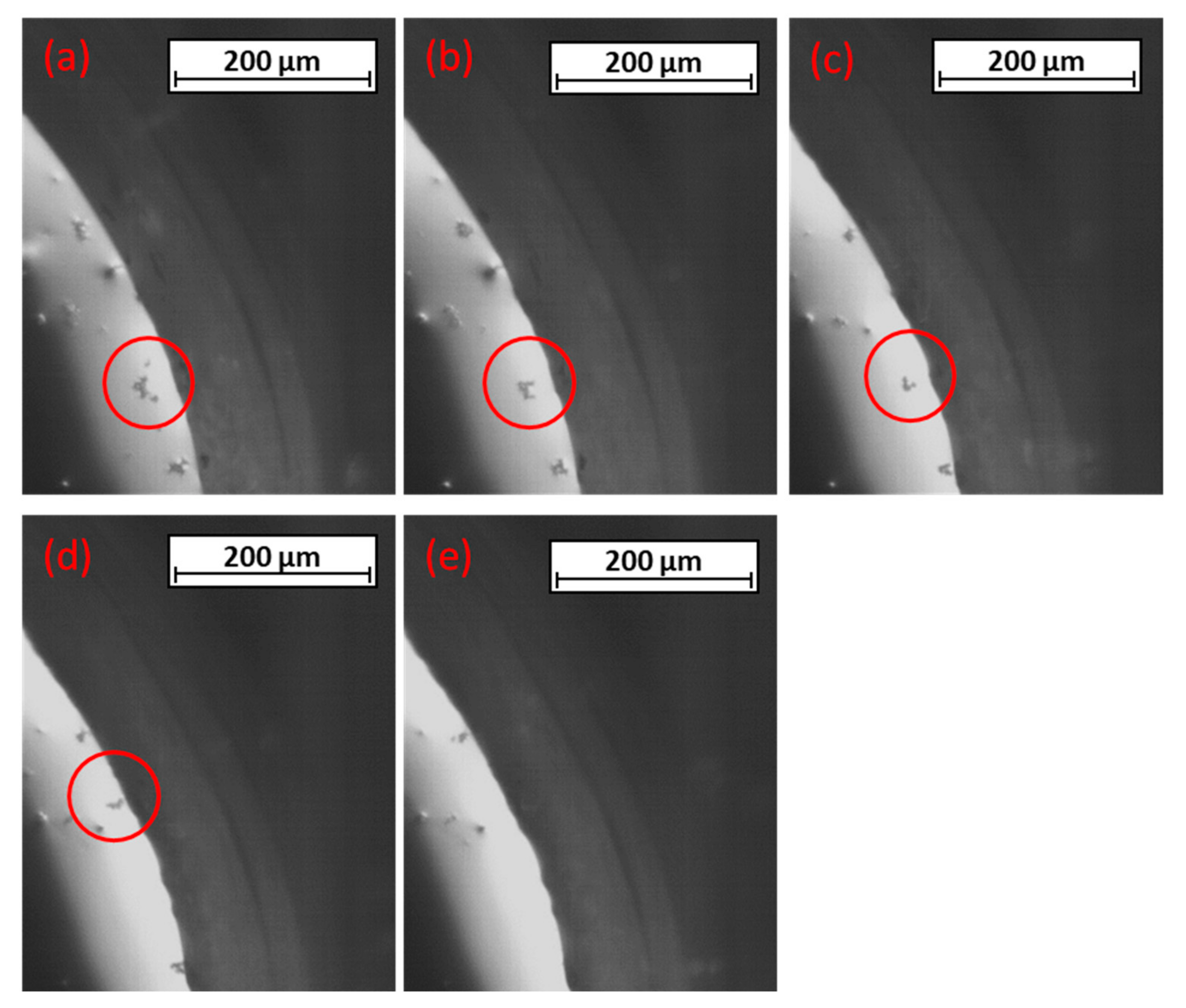
Focusing on one particular inclusion-agglomerate, further agglomeration to it was first visible, as can be seen in Figure 7a,b. The agglomerate moved toward the steel-slag interface, rotated around its own axis (Figure 7c,d), and decreased its size near the interface. As it touched the interface, the shrinking accelerated until it fully disappeared (Figure 7e). The measured temperature during this investigation was 1454 °C, which is between the steel’s calculated solidus and liquidus temperatures. The time steps between these frames were approximately two seconds each. For better observability the contrast was increased and the brightness decreased with image-processing software.
3.2. Metallographic Investigations
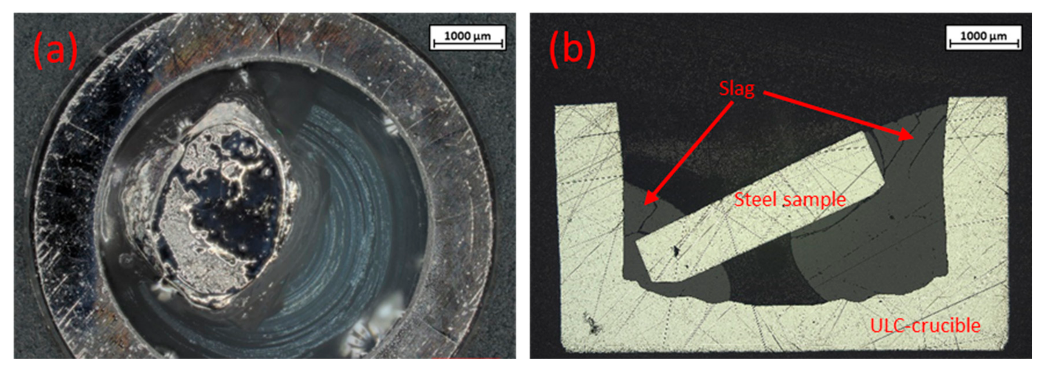
The crucible was removed from the furnace without the alumina crucible after the HT-CSLM experiment. This crucible was then investigated using a VHX digital microscope by KEYENCE International (Mechelen, Belgium). At the steel’s surface, agglomerates of non-metallic inclusions could be found. In Figure 8a, the partly molten steel plate with glassy solidified slag is shown in the micrograph set at a high depth of focus. It is obvious, that the slag remained transparent throughout the experiment. Due to surface tension, the molten slag contracted and thus pushed the steel plate to the side or even inclined it, as shown in Figure 8b. This phenomenon led to difficulties with focusing the steel plate in the HT-CSLM experiment.
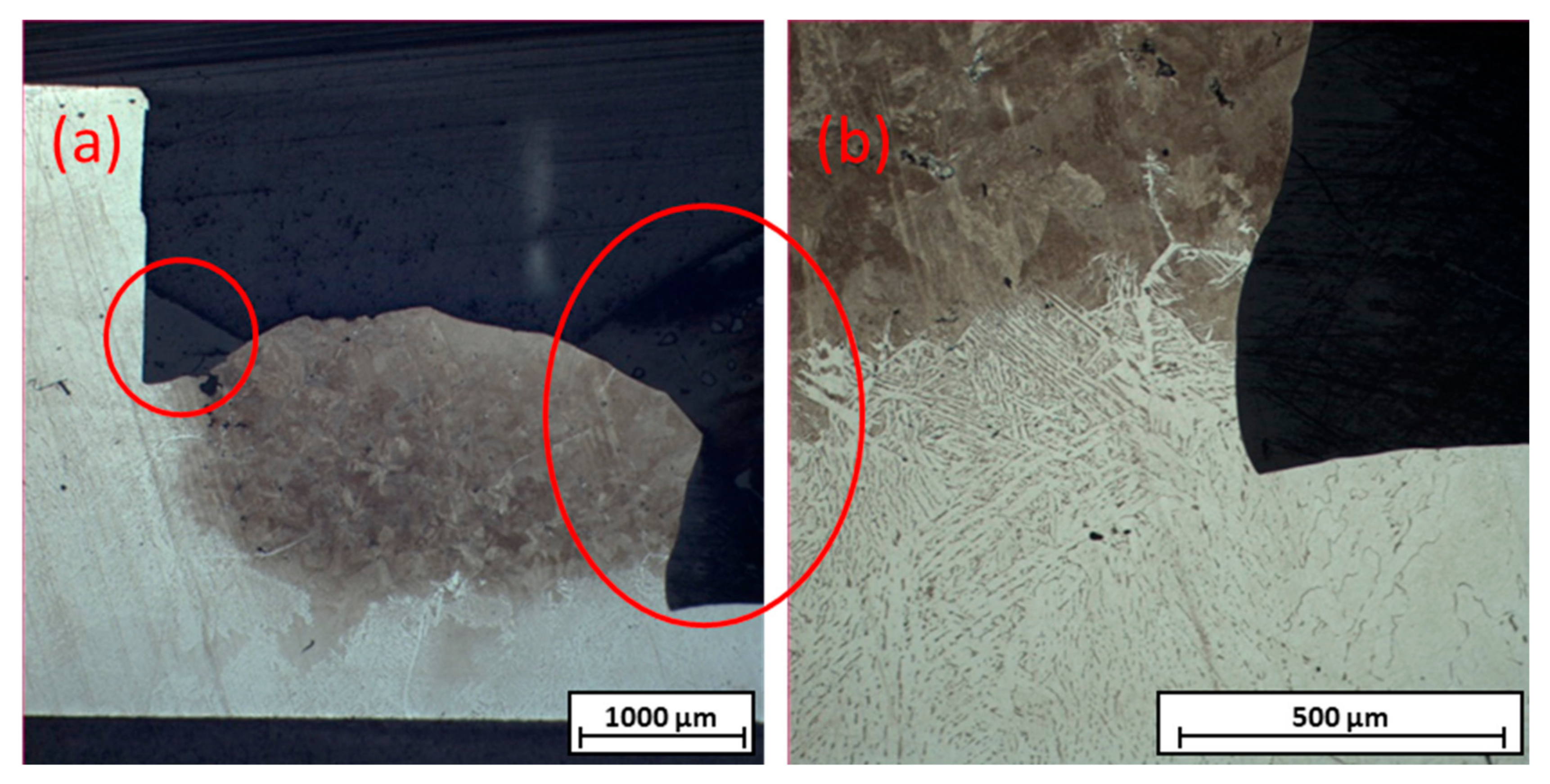
Afterward, the crucible was embedded into transparent medium, cut in half, ground, and polished to examine the interface between the steel sample plate and ULC-crucible. Nital etching revealed the interactions at this interface due to their differences in carbon content, as seen in Figure 9. It is obvious that, at the interface, both steel types interacted and welded together, and the crucible partially melted. The bottom line of it was unharmed. Due to the small color difference, the slag phase was not well visible. Therefore, it was marked on the left above and on the right side of the steel plate as grey areas.
4. Discussion and Outlook
These observed results as seen in the Figure 6, Figure 7, Figure 8 and Figure 9 are of a rather phenomenal nature. The main outcome was the observability of steel/slag interfaces on HT-CLSM with corresponding inclusion reactions, laying the essential foundation for further investigation and optimization. For more than 30 min, the slag stayed transparent enough to investigate the steel surface covered by it. Non-metallic inclusions could be found and tracked, starting at their appearance at the steel´s surface until they separated into the slag. The experiments on which the study is based have so far not provided any possibility of observing and following the particles after detachment from the steel/slag interface to the slag phase. This aspect is currently under further consideration.
Several restrictions in the experimental set-up occurred. The used slags had to be transparent throughout the experiment. Steels that release ions into the slag that tarnish the slag, such as chromium-alloyed steels, cannot be used for these experiments. Sodium, which lowers the melting point of slags, evaporates during heating and fogs deposits on the furnace walls, leading to reduced heat transfer and preventing the reaching of the required temperature in the crucibles. Further modifications of the above experiment, including different combinations of steels and slags, should be investigated. Furthermore, wetting issues of the steel/slag combination must be considered. They lead to incomplete coverage of the steel by the slag and the inclination of the steel specimen, leading to focusing on difficulties with HT-CLSM.
Author Contributions
Conceptualization, J.C. and S.K.M.; methodology, J.C.; validation, J.C., and S.K.M.; investigation, J.C. and S.K.M.; resources, J.C.; data curation, J.C.; writing—original draft preparation, J.C.; writing—review and editing, S.K.M.; visualization, J.C.; supervision, S.K.M.; project administration, S.K.M.; funding acquisition, S.K.M. All authors have read and agreed to the published version of the manuscript.
Funding
The financial support from the Austrian Federal Ministry for Labour and Economy; the National Foundation for Research, Technology and Development; and the Christian Doppler Research Association is gratefully acknowledged.
Data Availability Statement
The data presented in this study are available on request from the corresponding author.
Conflicts of Interest
The authors declare no conflict of interest.
References
- Mills, K.C. The Effect of Interfacial Phenomena on Materials Processing. In Interfacial Phenomena and the Marangoni Effect; Velarde, M.G., Sayir, M., Schneider, W., Schrefler, B., Bianchi, G., Tasso, C., Zeytounian, R.K., Velarde, M.G., Eds.; Springer: Wien, Austria, 2002; pp. 225–283. ISBN 978-3-211-83696-5. [Google Scholar]
- Jakobsson, A.; Du, S.; Seetharaman, S.; Viswanathan, N.N. Interfacial phenomena in some slag-metal reactions. Met. Mater. Trans. 2000, 31, 973–980. [Google Scholar] [CrossRef]
- Stolte, G. Secondary Metallurgy: Fundamentals, Processes, Applications; Unveränd. Nachdr; Verl. Stahleisen: Düsseldorf, Germany, 2007; ISBN 9783514006485. [Google Scholar]
- Ray, A.; Paul, S.; Jha, S. Effect of Inclusions and Microstructural Characteristics on the Mechanical Properties and Fracture Behavior of a High-Strength Low-Alloy Steel. JMEP 1995, 4, 679–688. [Google Scholar] [CrossRef]
- Zhang, L.; Thomas, B. Inclusions in continuous casting. XXIV Natl. Steelmak. Symp. 2003, 26–28, 138–183. [Google Scholar]
- Juvonen, P. Effects of Non-Metallic Inclusions on Fatigue Properties of Calcium Treated Steels; Helsinki University of Technology: Espoo, Finland, 2004; ISBN 9512274221. [Google Scholar]
- Byrne, M.; Fenicle, T.W.; Cramb, A.W. The Sources of exogenous Inclusions in Continuous Cast, Aluminium-Killed Steel. ISS Trans. 1989, 10, 51. [Google Scholar]
- Wang, Y.; Karasev, A.; Park, J.H.; Jönsson, P.G. Non-metallic Inclusions in Different Ferroalloys and Their Effect on the Steel Quality: A Review. Met. Mater. Trans. B 2021, 52, 2892–2925. [Google Scholar] [CrossRef]
- Michelic, S.; Bernhard, C.; Hartl, M. Thermodynamic and Experimental Study on the Modification of Non-Metallic Inclusions through Contact with CaO−Al₂O₃−MgO Slags. In Proceedings of the AISTech Proceedings, Indianapolis, IN, USA, 2–5 May 2011; Michelic, S.K., Hartl, M., Bernhard, C., Eds.; AIST—Association for Iron & Steel Technology: Indianapolis, IN, USA, 2011. [Google Scholar]
- Reis, B.H.; Bielefeldt, W.V.; Vilela, A.C.F. Absorption of non-metallic inclusions by steelmaking slags—A review. J. Mater. Res. Technol. 2014, 3, 179–185. [Google Scholar] [CrossRef] [Green Version]
- Liu, C.; Gao, X.; Ueda, S.; Guo, M.; Kitamura, S. Composition Changes of Inclusions by Reaction with Slag and Refractory: A Review. ISIJ Int. 2020, 60, 1835–1848. [Google Scholar] [CrossRef]
- Zhang, X.; Pirker, S.; Saeedipour, M. Numerical investigation of particle motion at the steel—Slag interface in continuous casting using VOF method and dynamic overset grids. Exp. Comput. Multiph. Flow 2023, 5, 178–191. [Google Scholar] [CrossRef]
- Liu, W.; Yang, S.; Li, J.; Wang, F.; Yang, H. Numerical model of inclusion separation from liquid metal with consideration of dissolution in slag. J. Iron Steel Res. Int. 2019, 26, 1147–1153. [Google Scholar] [CrossRef]
- Khorasani, M.; Gibson, I.; Ghasemi, A.H.; Hadavi, E.; Rolfe, B. Laser subtractive and laser powder bed fusion of metals: Review of process and production features. RPJ, 2023; ahead-of-print. [Google Scholar] [CrossRef]
- Presoly, P.; Pierer, R.; Bernhard, C. Identification of Defect Prone Peritectic Steel Grades by Analyzing High-Temperature Phase Transformations. Metall. Mater. Trans. A 2013, 44, 5377–5388. [Google Scholar] [CrossRef]
- Fuchs, N.; Krajweski, P.; Bernhard, C. In-situ Observation of Austenite Grain Growth in Plain Carbon Steels by Means of High-Temperature Laser Scanning Confocal Microscopy. Berg Und Hüttenmännische Mon. 2015, 160, 214–220. [Google Scholar] [CrossRef]
- Hu, H.; Xu, G.; Nabeel, M.; Dogan, N.; Zurob, H.S. In Situ Study on Interrupted Growth Behavior and Crystallography of Bainite. Metall. Mater. Trans. A 2021, 52, 817–825. [Google Scholar] [CrossRef]
- Tian, J.; Xu, G.; Jiang, Z.; Hu, H.; Yuan, Q.; Wan, X. In-Situ Observation of Martensitic Transformation in a Fe–C–Mn–Si Bainitic Steel During Austempering. Met. Mater. Int. 2020, 26, 961–972. [Google Scholar] [CrossRef]
- Mu, W.; Dogan, N.; Coley, K.S. In Situ Observations of Agglomeration of Non-metallic Inclusions at Steel/Ar and Steel/Slag Interfaces by High-Temperature Confocal Laser Scanning Microscope: A Review. JOM 2018, 70, 1199–1209. [Google Scholar] [CrossRef]
- Wikström, J.; Nakajima, K.; Shibata, H.; Tilliander, A.; Jönsson, P. In situ studies of agglomeration between Al2O3–CaO inclusions at metal/gas, metal/slag interfaces and in slag. Ironmak. Steelmak. 2008, 35, 589–599. [Google Scholar] [CrossRef]
- Coletti, B.; Vantilt, S.; Blanpain, B.; Sridhar, S. Observation of Calcium Aluminate Inclusions at Interfaces between Ca-Treated, Al-Killed Steels and Slags. Metall. Mater. Trans. B 2003, 34, 533–538. [Google Scholar] [CrossRef]
- Feichtinger, S.; Michelic, S.K.; Kang, Y.-B.; Bernhard, C. In-situ observation of the dissolution of SiO₂ particles in CaO−Al₂O₃−SiO₂ slags and mathematical analysis of its dissolution pattern. J. Am. Ceram. Soc. 2014, 97, 316–325. [Google Scholar] [CrossRef]
- Harmuth, H. Evaluation of CLSM measurements for dissolution studies—A case study investigating alumina dissolution in a silicate slag. Ceram. Int. 2022, 48, 28174–28180. [Google Scholar] [CrossRef]
- Preisser, N.; Cejka, J.; Babu, S.R.; Klösch, G.; Michelic, S.K. Dissolution of Al2O3, MgO∙Al2O3 and SiO2 in alkali oxide containing secondary metallurgical slags. In Proceedings of the Liquid Metal Processing & Casting Conference 2022, Philadelphia, PA, USA, 18–21 September 2022; pp. 87–96, ISBN 0-87339-772-X/978-0-87339-772-8. [Google Scholar]
- Sharma, M.; Mu, W.; Dogan, N. In Situ Observation of Dissolution of Oxide Inclusions in Steelmaking Slags. JOM 2018, 70, 1220–1224. [Google Scholar] [CrossRef]
- Monaghan, B.J.; Chen, L. Dissolution behavior of alumina micro-particles in CaO-SiO2-Al2O3 liquid oxide. J. Non-Cryst. Solids 2004, 347, 254–261. [Google Scholar] [CrossRef]
- Thiele, K.; Presoly, P.; Ernst, D.; Babu, S.R.; Michelic, S.K. Evaluation of different alloying concepts to trace non-metallic inclusions by adding rare earths on a laboratory scale. Ironmak. Steelmak. 2022, 1–10. [Google Scholar] [CrossRef]
Figure 1.
Backscattered electron (BSE) image and elemental mapping of inclusions: (a) iron sulfide; (b) alumina cluster; (c) single alumina inclusion.
Figure 1.
Backscattered electron (BSE) image and elemental mapping of inclusions: (a) iron sulfide; (b) alumina cluster; (c) single alumina inclusion.


Figure 2.
(a) Experimental set-up without slag chunks; (b) and with slag chunks. (c) Schematic drawing of dual-crucible set-up with (1) alumina crucible; (2) ULC crucible; (3) steel specimen; and (4) slag specimen chunks.
Figure 2.
(a) Experimental set-up without slag chunks; (b) and with slag chunks. (c) Schematic drawing of dual-crucible set-up with (1) alumina crucible; (2) ULC crucible; (3) steel specimen; and (4) slag specimen chunks.

Figure 3.
Set-up during experiment liquid steel pool covered by molten slag.

Figure 4.
(a) Glassy slag chunks; (b) melting of slag; (c) liquid slag over steel plate.

Figure 5.
(a) Melting of the plate at the grain boundaries and steel/slag/gas interface; (b,c) melting below the slag surface.
Figure 5.
(a) Melting of the plate at the grain boundaries and steel/slag/gas interface; (b,c) melting below the slag surface.

Figure 6.
Partly molten steel covered with slag on the right and visible inclusions.

Figure 7.
(a–e) Movement, agglomeration, and dissolution of the non-metallic inclusion.

Figure 8.
Microscopic evaluation of two crucibles: (a) with high depth of focus; (b) cross section.

Figure 9.
(a) Nital etching of crosscut of crucible after experiment with marked slag; (b) Magnification of the mixed zone.
Figure 9.
(a) Nital etching of crosscut of crucible after experiment with marked slag; (b) Magnification of the mixed zone.


Table 1.
Chemical analysis of investigated slags by XRF (for CaO, Al2O3 and SiO2) and ICP-OES (for Li2O and Na2O).
Table 1.
Chemical analysis of investigated slags by XRF (for CaO, Al2O3 and SiO2) and ICP-OES (for Li2O and Na2O).
| Species wt.% | SiO2 | CaO | Al2O3 | Li2O | Na2O |
|---|---|---|---|---|---|
| Li-slag | 47.2 | 41.8 | 4.8 | 6.2 | - |
| Na-slag | 45.6 | 39.1 | 6.3 | - | 6.0 |
Table 2.
Chemical analysis of investigated steel analyzed by optical emissions spectrometer (OES).
| Species wt.% | C | Si | Al | S | Fe |
|---|---|---|---|---|---|
| Steel plate | 0.5 | 1.1 | 0.4 | 0.0034 | bal. |
Disclaimer/Publisher’s Note: The statements, opinions and data contained in all publications are solely those of the individual author(s) and contributor(s) and not of MDPI and/or the editor(s). MDPI and/or the editor(s) disclaim responsibility for any injury to people or property resulting from any ideas, methods, instructions or products referred to in the content. |
© 2023 by the authors. Licensee MDPI, Basel, Switzerland. This article is an open access article distributed under the terms and conditions of the Creative Commons Attribution (CC BY) license (https://creativecommons.org/licenses/by/4.0/).
Share and Cite
MDPI and ACS Style
Cejka, J.; Michelic, S.K. In-Situ Observation of Steel/Slag/Inclusion Interaction by Means of High-Temperature Confocal Scanning Laser Microscopy. Metals 2023, 13, 686. https://doi.org/10.3390/met13040686
AMA Style
Cejka J, Michelic SK. In-Situ Observation of Steel/Slag/Inclusion Interaction by Means of High-Temperature Confocal Scanning Laser Microscopy. Metals. 2023; 13(4):686. https://doi.org/10.3390/met13040686
Chicago/Turabian StyleCejka, Julian, and Susanne Katharina Michelic. 2023. "In-Situ Observation of Steel/Slag/Inclusion Interaction by Means of High-Temperature Confocal Scanning Laser Microscopy" Metals 13, no. 4: 686. https://doi.org/10.3390/met13040686
Note that from the first issue of 2016, this journal uses article numbers instead of page numbers. See further details here.