Review

Ultrafine-Grained Stainless Steels after Severe Plastic Deformation

1
Laboratory of Mechanical Properties of Nanostructured Materials and Superalloys, Belgorod National Research University, Belgorod 308015, Russia
2
Moscow Timiryazev Agricultural Academy, Russian State Agrarian University, Moscow 127550, Russia
*
Author to whom correspondence should be addressed.
Metals 2023, 13(4), 674; https://doi.org/10.3390/met13040674
Submission received: 28 February 2023 / Revised: 17 March 2023 / Accepted: 25 March 2023 / Published: 29 March 2023
(This article belongs to the Section Metal Casting, Forming and Heat Treatment)

Abstract

:
The aim of the present review is to summarize the recent achievements in the development of ultrafine-grained austenitic/ferritic stainless steels processed by large strain deformation. Various aspects of microstructure evolution and its effect on the properties of processed steels are considered. The paper starts from an overview of various methods of large strain deformation that are successfully used for producing ultrafine-grained metallic materials. Then, the structural mechanisms responsible for grain refinement during plastic deformation are considered and discussed from the viewpoint of their efficiency and effect on the subsequent recrystallization behavior. Finally, some physical and mechanical properties of ultrafine-grained stainless steels are observed. It is concluded that the development of ultrafine-grained microstructures during severe plastic deformation results from a kind of continuous dynamic recrystallization. Namely, the misorientations among the strain-induced cells/subgrains progressively increase up to typical values of ordinary grain boundaries. Following the rapid reduction at relatively small strains, the deformation grain size gradually approaches its final value, which depends on alloying/phase content and processing conditions. An increase in the number density of interface/grain boundaries in the initial state significantly accelerates the kinetics of grain refinement during subsequent plastic working.

1. Introduction

Currently, stainless steels with ultrafine-grained (UFG) microstructures are considered as promising materials for certain applications, when corrosion resistance combined with improved mechanical properties such as high strength and sufficient ductility along with enhanced impact toughness is required [1,2,3,4,5,6,7,8,9]. Commonly, recrystallization is applied to control the developed microstructures in bulky metallic materials [10]. Of particular importance is dynamic recrystallization (DRX) resulting in the desired grain size directly during plastic deformation [11,12,13,14,15]. The main regularities of DRX have been fairly clarified in a number of papers [16,17,18,19,20]. The DRX grain size decreases with a decrease in deformation temperature and/or an increase in strain rate. Therefore, the substantial grain refinement can be obtained through plastic deformation at relatively low temperatures. However, the strain, which is required for the DRX development, increases significantly with a decrease in the processing temperature. Therefore, one of the recent approaches to produce ultrafine-grained stainless steels involves severe plastic deformation (SPD), which is actually large strain (or redundant strain) deformation at relatively low temperatures [21,22,23]. Typical strains imposed by SPD vary in a very large range, depending on material and processing conditions. The strain corresponding to steady-state deformation behavior can be considered as a sufficiently large one. The aim of the present paper is to summarize the latest achievements in the development of UFG stainless steels by means of SPD, to clarify the microstructure–property relationships in UFG stainless steels, and to make clear the prospects for producing and application of these materials.
A number of specific processing methods have been developed to date to impose large strains on processed material at low to moderate temperatures [4,21,24,25,26,27,28]. It should be noted that large strain deformation can be also achieved by some conventional metal-forming methods such as drawing and rolling. The latter ones are simple in utilization and can be applied by using ordinary equipment. Recently, rolling, swaging, and forging have been successfully applied to process several ultrafine-grained stainless steels [29,30,31]. These conventional methods will be considered in comparison with some special SPD techniques in Section 2, discussing their benefits and detriments. Then, the mechanisms of the microstructure evolution leading to UFG formation in various stainless steels will be considered and discussed in Section 3 starting from a brief review of novel experimental techniques developed recently to investigate the deformation microstructures in metallic materials. Specific attention will be paid to the grain refinement kinetics and dependence on processed material and processing conditions. Following the deformation microstructures, the effect of annealing on the change in the UFG microstructures will be considered in Section 4. The main properties of stainless steels, namely strength–plasticity combination and corrosion resistance, will be reviewed in Section 5 and Section 6, respectively. Finally, the prospects for processing and utilization of UFG stainless steels will be outlined in Section 7.

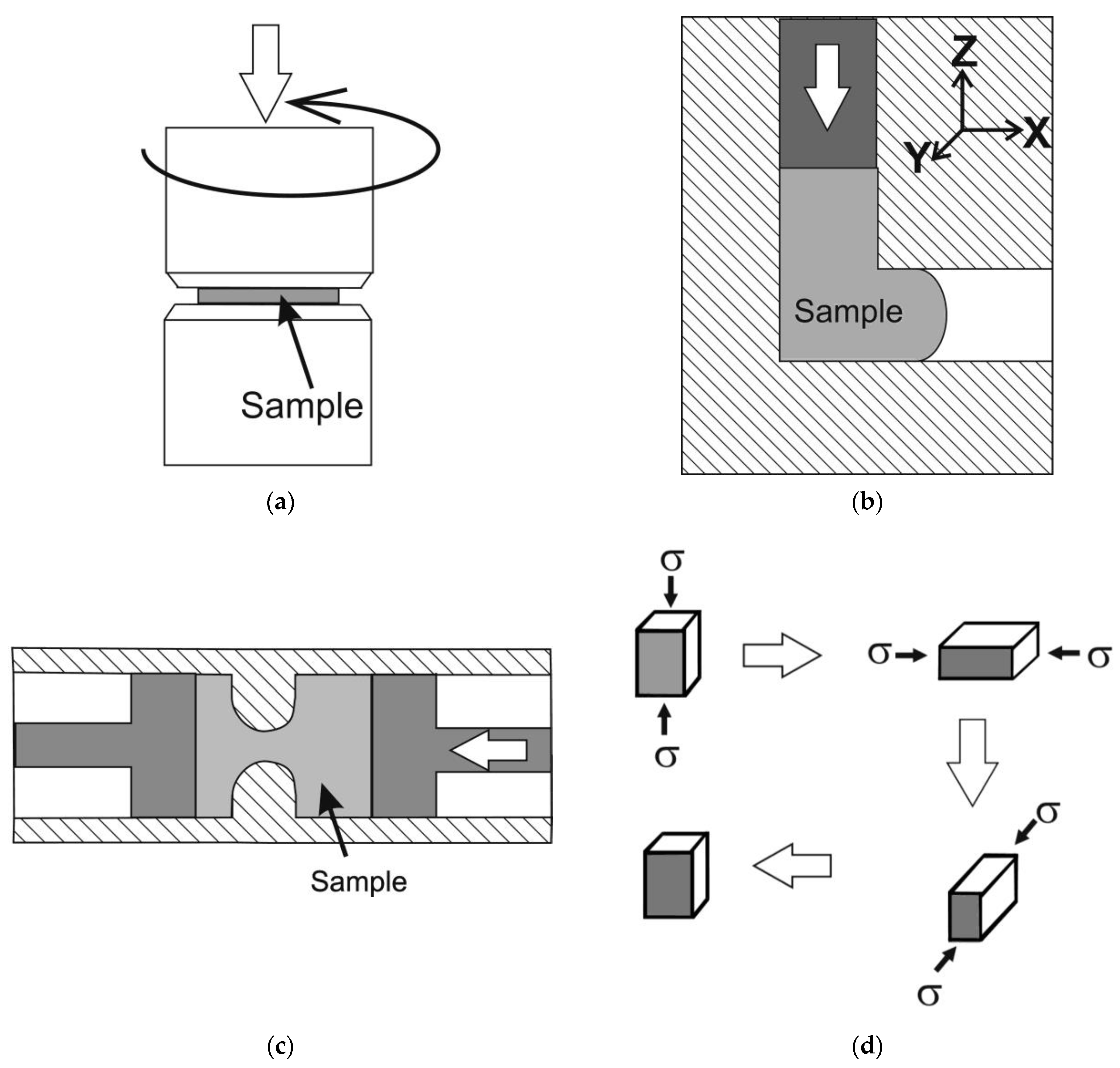
2. Large-Strain Processing

Renewed about 50 years ago, interest in large-strain processing, i.e., SPD, was motivated by two achievements. Those are the obtained ultrafine-grained and nanocrystalline metals and alloys with reportedly outstanding properties [32] and the success in application of special SPD methods [4]. One of the most frequently used SPD methods is torsion under hydrostatic pressure (HPT) which was adapted from the Bridgeman anvil [33,34]. The sample as a thin disc is subjected to torsion around the disc axis using the friction provided by the large hydrostatic pressure of about 5 GPa (Figure 1a). Equivalent strains well above 100 that may lead to a nanocrystalline microstructure in various metallic materials can be applied with HPT [34,35]. A disadvantage of HPT is associated with a limitation of the process within a small-scale laboratory investigation.
Following the principles outlined by Segal et al. [36], another SPD method, i.e., equal-channel angular pressing (ECAP) was developed and successfully applied for processing rather ductile materials [21,37] (Figure 1b). During ECAP, the sample is pressed in a closed die with two equal-sized channels intersecting at an angle of φ resulting in a strain of γ = 2 cot φ/2 [21]. In the case of a number (N) of sequential ECAP passes, the strains are commonly summed, and an equivalent strain can be defined as follows [36]:
ε = (2N/√3) cot φ/2,
Compared to HPT, ECAP requires costly equipment and cannot be applied for materials with limited ductility, although ECAP combined with the CONFORM process [38] can be used for sizeable samples.
A number of well-known conventional metal-forming techniques also allow obtaining very large strains. Many industrial processing methods such as rolling, drawing, and swaging can be also used for large strain deformation [39] leading to UFG evolution in various metals and alloys. These methods are quite easy to utilize because they can be carried out using standard tools. It should be noted that certain dimensions of the processed sample are continuously reduced during deformation. This drawback limits the practical application of unidirectional processing methods such as SPD for producing UFG structural materials. On the other hand, the same drawback stimulates investigations dealing with the control of the UFG evolution kinetics in order to obtain the desired UFG microstructure in bulky products suitable for practical applications after reasonable strains.
There are several methods of large strain deformations retaining the original shape of the processed sample without substantial changes. Those are commonly cyclic in realization and based on reversing the strain path for each cycle, providing redundant deformation with reversible change in the shape of the processed sample [21]. Among those, reversing extrusion [25] and multiple forging [40] seem to be the most effective and elaborated (Figure 1c,d). The former provides very large strains for constrained samples, although some difficulties maybe experienced in processing hard-to-deform materials. Multiple forging is one of the simplest and most easily realized methods, accumulating large total strain in the samples with sufficient plasticity. The total strain can be estimated by a summation of the strain in each forging pass, i.e., ε = ln (Hi/Hf), where Hi and Hf are the initial and final heights of the sample. In contrast to other SPD techniques, multiple forging (sometimes called ABC forging [41]) allows obtaining the relationship between true stress and true strain, which is very important for understanding the microstructure–property relations [42,43]. Besides the SPD techniques mentioned above, there are many other specific SPD methods that should also be noted, such as accumulative roll-bonding [44], friction stir processing [45], continuous cyclic bending [46], repetitive corrugation and straightening [47], mechanical milling [48,49], and hydrostatic extrusion [50] and its modification for long-scale samples [51].

3. Ultrafine-Grained Microstructures

UFG steels and alloys are those with a grain size of less than 1 μm [52]. Moreover, UFG microstructures developed by SPD involve high dislocation density in the form of cell walls and sub-boundaries [14]. Such a mixture of fine grains/cells/subgrains with large internal distortions complicates the microstructural investigations of UFG materials. Usually, UFG microstructures are studied by means of transmission electron microscopy (TEM). High-resolution TEM reveals fine details of deformation microstructures, including the mutual arrangement of strain-induced boundaries/sub-boundaries and lattice dislocations, although arduous specimen preparation and limited observation area consume a lot of researchers’ time and energy.
Recently, the powerful technique of orientation imaging microscopy (OIM) based on the automatic analysis of Kikuchi patterns from backscattered electrons in a scanning electron microscope has been developed and introduced for comprehensive microstructural analysis [53]. OIM consists in the systematic measurement of the crystallographic orientation on the surface of the sample section from point to point throughout the arbitrarily selected area. The resulting maps of the distribution of orientations open up great opportunities for microstructural analysis [54]. The results obtained make it possible to reveal the boundaries of grains/subgrains and their characteristics. OIM allows characterizing the spectrum of misorientations, which is one of the most important characteristics of the deformation microstructure. Since OIM maps can include up to several tens of thousands of grains/subgrains, large statistics can also be included in the key advantages of this method. Regarding crystallographic textures, OIM may well compete with X-ray diffraction. The benefits of OIM include a wide choice of treating the data, which can be represented as any (at the user’s choice) pole figure or orientation distribution function [54]. The rapid development of OIM over the past few decades makes it possible to successfully use OIM for studying even very complex structures, such as nanocrystalline [55,56] and severely deformed [57,58] structures. Therefore, OIM will be given preference when available while considering the UFG microstructures developed in stainless steels subjected to SPD.

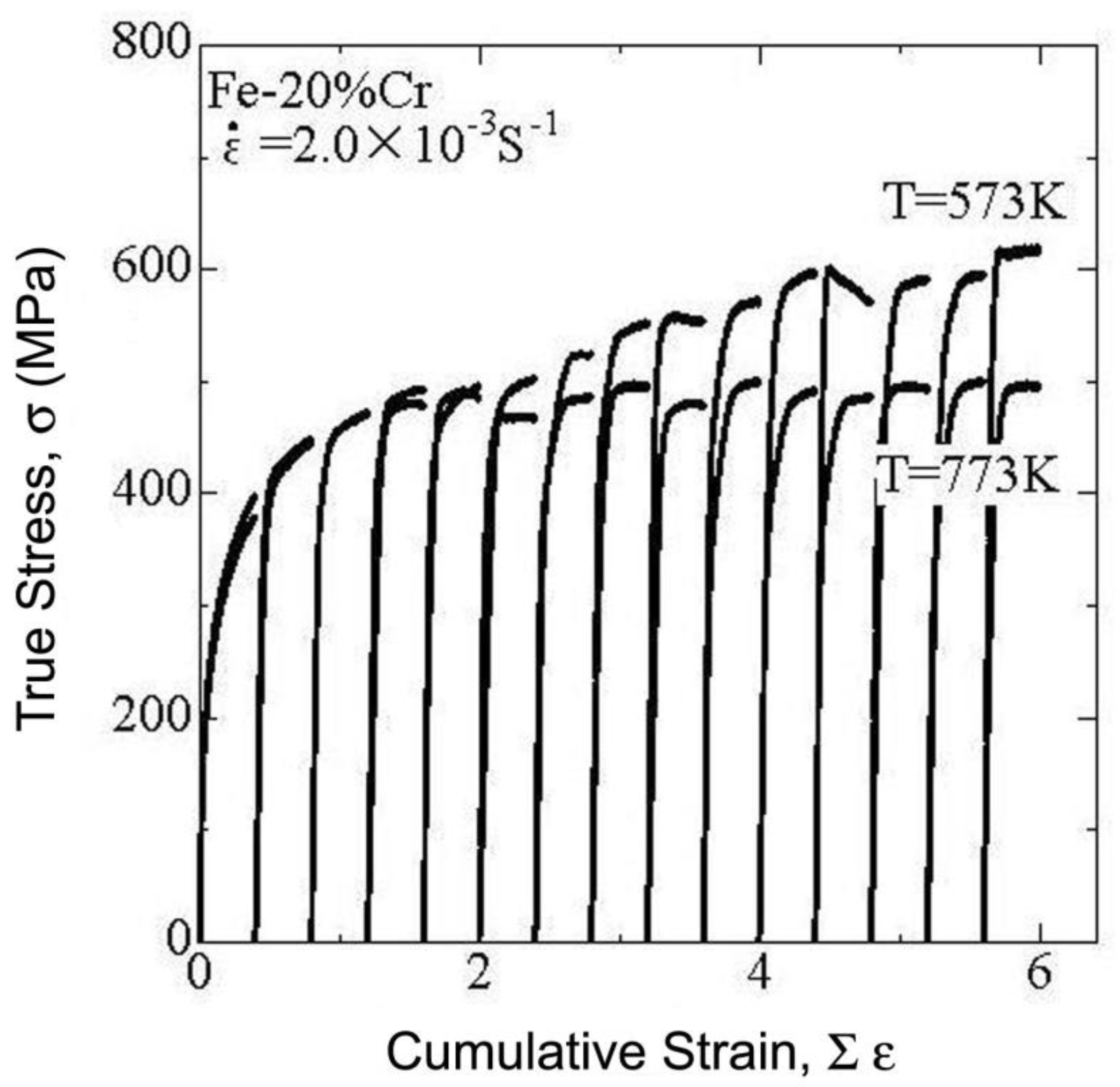
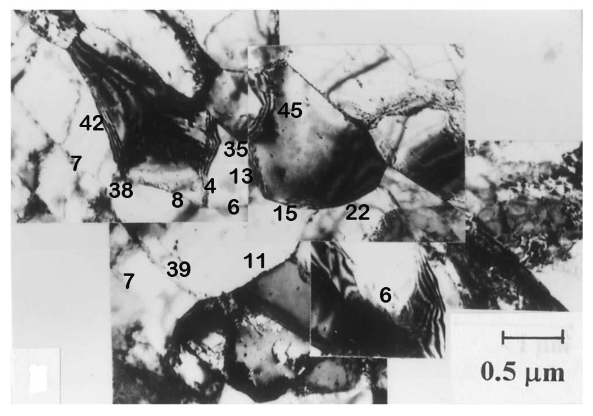
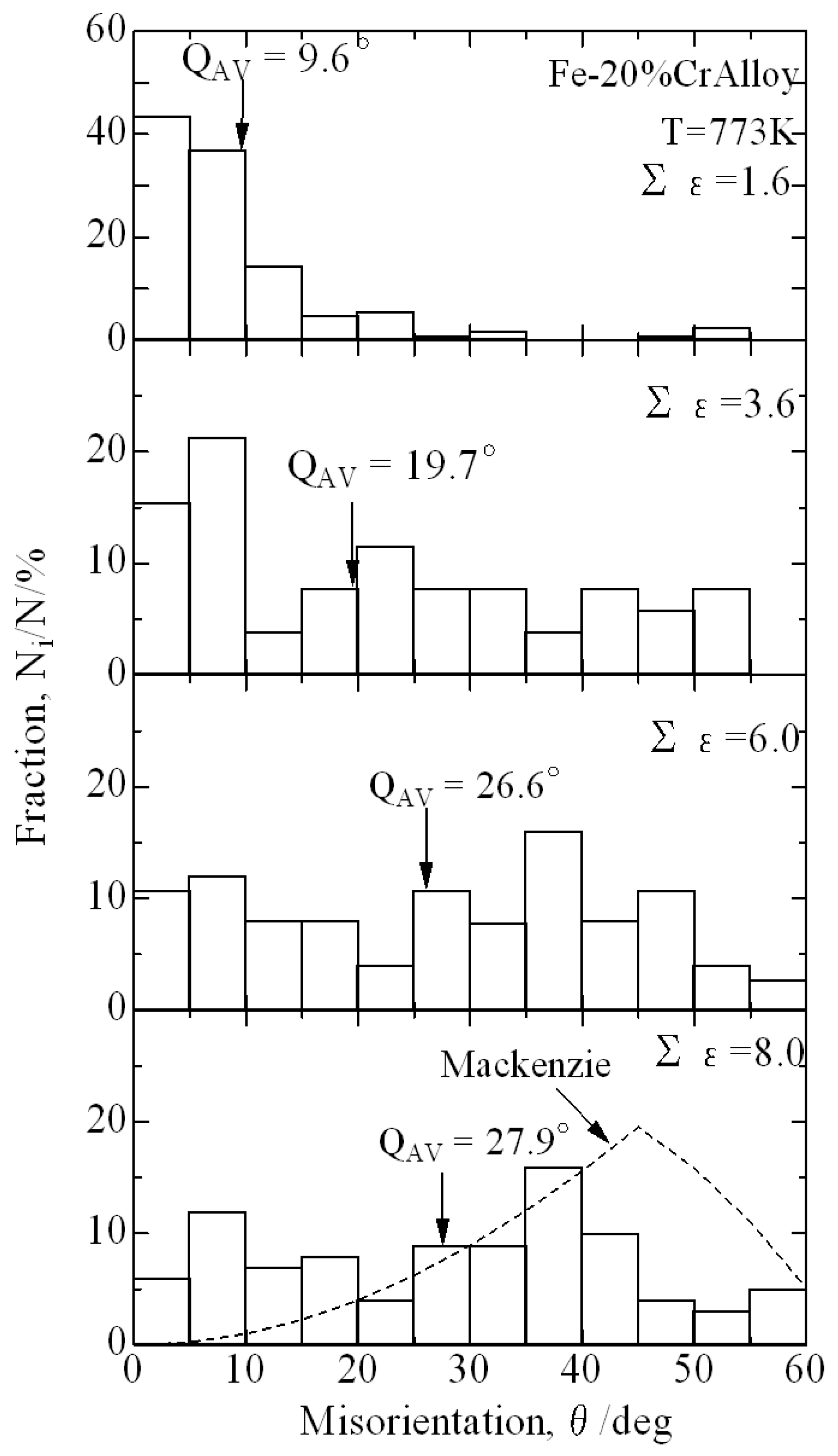
3.1. Evolution of Deformation Microstructures

3.1.1. Ferritic Stainless Steels

Ferritic stainless steels are highly susceptible to dynamic recovery. The flow stress upon deformation of ferritic steel sample increases with straining and approaches saturation at sufficiently large strains [59]. The saturation stress level depends on processing conditions, i.e., temperature and strain rate [16]. It is interesting that similar deformation behavior takes place in ferritic steels during SPD. The flow stresses vs. strain for a ferritic stainless steel subjected to multiple forging to a large total strain of 6 are shown in Figure 2 [60]. The envelope curves plotted over stress–strain curves for 15 sequential compression passes look very similar to those upon monotonous processing that is accompanied by dynamic recovery. The flow curve envelope suggests a remarkable strain hardening at early deformation followed by a decrease in the hardening rate to zero during subsequent processing that results in a steady-state-like deformation behavior at large cumulative strains. An increase in deformation temperature from 573 K to 773 K decreases the steady-state flow stress from about 600 MPa to 500 MPa, as shown in Figure 2. An attenuating strain hardening was reported for various metallic materials, even for cold working conditions, while increasing the dislocation density promoted the dislocation rearrangement [61]. However, the steady-state deformation behavior with strain-invariant flow stress as recorded through multiple compressions to large strains is indicative of the dynamically stable deformation microstructures, while the main microstructural parameters remain unchanged during further processing.
Typical deformation microstructures evolved in a Fe-25%Cr steel during warm working to a strain of 0.7 are represented in Figure 3 [59]. The main feature of the microstructures developed at moderate strains is a significant heterogeneity that is, especially, clearly seen near the original grain boundary (GB) in Figure 3a. This heterogeneity is associated with numerous microshear bands (MBs in Figure 3b) crossing over original grains with high dislocation density as dense dislocation walls (DDWs). An enlarged portion of such a microshear band is represented in Figure 4. The band consists of fine largely misoriented grains/subgrains and can be considered as a region of UFG microstructure. The number and thickness of the microshear bands increase upon multiple forging. Thus, the UFG regions expand over deformation substructures (Figure 5) [60]. A mixed microstructure consisting of almost equiaxed UFG and high-dislocation-density substructure evolves at a moderate strain level of 2–4, which corresponds to the beginning of the steady-state deformation. A ring-type electron diffraction pattern in Figure 5a suggests large angular misorientations in this microstructure. Then, the UFG microstructure propagates throughout the forged sample after SPD to a total large strain of 8 (Figure 5b). The developed microstructure is composed of highly misoriented ultrafine grains with a relatively low dislocation density in their interiors.
The development of UFG microstructures during SPD is commonly attributed to continuous DRX [14]. Continuous DRX consists in the development of strain-induced cells/subgrains and their progressive rotation during plastic deformation that leads to a gradual increase in the cell/sub-boundary misorientations up to typical values of ordinary high-angle grain boundaries. Therefore, the progress of continuous DRX can be tracked by the change in the boundary/sub-boundary misorientation distribution during SPD. Typical misorientation distributions developed in Fe-20%Cr steel subjected to multiple forging to various total strains are represented in Figure 6 [60]. The misorientation distribution after relatively small strains involves a large peak for low-angle sub-boundaries and some high-angle boundaries resulting from fine regions in microshear bands and their intersections. The fraction of low-angle sub-boundaries gradually decreases while that of high-angle boundaries increases upon further SPD, leading to almost equal fractions of various grain/subgrain boundaries in the misorientation distribution after large strains.
The kinetics of continuous DRX significantly depends on the temperature of SPD. Deformation temperature scarcely affects the UFG development at the early stage of the evolutional process, when the deformation microstructures are mostly represented by only dislocation cells/subgrains (Figure 7) [60]. On the other hand, the fraction of high-angle boundaries rapidly increases to apparent saturation during SPD in the range of large cumulative strains. It is worth noting that the level of such saturation substantially depends on processing temperature. For instance, an increase in temperature of multiple forging from 573 K to 773 K provided an increase in the fraction of high-angle boundaries from about 30% to 70% in Fe-20%Cr steel after a total strain of 6. This suggests that the development of continuous DRX resulting in the UFG microstructures during SPD depends on dynamic recovery similar to that under conditions of hot working [20].

3.1.2. Austenitic Stainless Steels

In contrast to ferritic stainless steels, austenitic steels with face-centered cubic lattice and low stacking fault energy are less susceptible to dynamic recovery. Hence, austenitic stainless steels exhibit pronounced strain hardening and, therefore, frequently experience discontinuous DRX during warm to hot working [62,63,64]. Nevertheless, SPD of austenitic stainless steels under conditions of cold to warm working results in the UFG microstructures that are commonly attributed to continuous DRX [65,66,67,68].
The general shape of the envelope stress–strain curves as plotted in Figure 8 over a series of multiple forgings of a 304-type stainless steel depends on deformation temperature [65,69]. Generally, two kinds of deformation behavior can be distinguished. Dynamic recovery type is observed during deformation at the relatively low temperature of 773 K. Namely, early deformation is accompanied by a rapid increase in the flow stress. Then, the rate of strain hardening gradually decreases, leading to the flow stress approaching saturation after large cumulative strains very similar to the deformation behavior of ferritic stainless steels. On the other hand, the deformation behavior of the discontinuous DRX type can be recognized during multiple forging at temperatures above 873 K. The envelope flow curve shows a peak at moderate cumulative strains followed by a strain softening and then a steady-state deformation at sufficiently large strains. The strain corresponding to peak stress decreases with an increase in deformation temperature similar to discontinuous DRX taking place under hot working conditions [14].
Typical deformation microstructures evolved in a 304-type stainless steel during multiple multidirectional forging at 773 K are shown in Figure 9 [70]. A number of strain-induced grain boundaries are clearly seen in the sample subjected to three sequential forging passes to a total strain of 1.2. The new ultrafine grains frequently develop along original grain boundaries and their triple junctions, where large strain gradients and corresponding high density of strain-induced boundaries evolve. The number of new fine grains and the volume fraction of ultrafine grains increase during SDP, leading to UFG microstructure after sufficiently large total strain (ε = 4 after ten forging passes in Figure 9). An increase in SPD temperature does not lead to qualitative changes in the microstructure evolution, although individual uncompleted strain-induced boundaries are observed near original grain boundaries and their junctions after one forging pass at 973 K (arrows for ε = 0.4 in Figure 10) [70]. Further processing results in the mixed microstructure consisting of irregular remnants of original grains and strain-induced ultrafine grains. An increase in processing temperature under conditions of warm working apparently accelerates the development of UFG microstructure in the austenitic stainless steel. The UFG fraction in the sample subjected to multiple forging at 973 K to a total strain of 2 comprises about 0.9, whereas that of about 0.6 is observed at 773 K after the same strain. Therefore, an increase in deformation temperature promotes the development of continuous DRX during warm deformation similar to that discussed above for ferritic stainless steels.
The change in the grain size distributions during multiple forging at 773 K or 973 K is represented in Figure 11 [70]. A huge peak corresponding to rather coarse original grains is observed at a relatively small strain. This peak decreases and spreads out towards small grain sizes during further SPD. It should be noted that a kind of bimodal grain size distribution with two peaks against small and large grain sizes evolves at intermediate strains. Thus, the development of UFG microstructure is accompanied by an increase in the peak at small grain sizes and gradual disappearance of the peak at large grain sizes. Finally, a peak corresponding to the new ultrafine grains stands up in the grain size distribution evolved at sufficiently large total strains. Such changes in the grain size distribution were frequently observed during discontinuous DRX under hot working conditions [10]. It can be concluded that the changes in the grain size distributions during DRX are almost the same irrespective of different DRX mechanisms.
The fraction of discontinuous DRX (FDRX) can be expressed by a modified Johnson–Mehl–Avrami–Kolmogorov (JMAK) equation [71].
FDRX = 1 − exp(−k (ε − εc)n),
where k, n, and εc are constants depending on material and processing conditions. Neglecting the incubation period for continuous DRX, i.e., εc = 0, the relationships between log(ln(1/(1 − FDRX))) and log (ε) for a 304-type stainless steel subjected to multiple forging at 773–973 K are represented in Figure 12a [70]. Then, the strain effect on the UFG fraction is shown in Figure 12b [70]. It is clearly seen that an increase in deformation temperature from 773 K to 873 K insignificantly increases the grain refinement kinetics, whereas further temperature rise to 973 K remarkably accelerates the UFG evolution. Similar DRX behavior was attributed to the effect of dynamic recovery [20].
The UFG microstructures evolved in austenitic stainless steel during large strain deformation at temperatures above 0.5TM were characterized by a relatively large fraction of annealing twins (up to 0.12 [69]). This is indicative of the grain boundary migration [72,73] and, therefore, suggests a contribution of discontinuous DRX to the new UFG development. Taking into account the possibility of discontinuous DRX development in austenitic stainless steels, the mechanisms of UFG evolution during SPD were considered as follows (Figure 13 [65]): The strain corresponding to peak flow stress is used as critical strain for discontinuous DRX (DDRX in Figure 13) development, while the progress in continuous DRX (CDRX in Figure 13) is indicated by the fractions of high-angle grain boundaries. The critical strain for discontinuous DRX increases with a decrease in deformation temperature. Hence, continuous DRX becomes responsible for the UFG development during deformation at temperatures below about 973 K (about 0.55TM) in a 304-type stainless steel.
It should be noted that continuous DRX does not suppress the local migration of original and strain-induced grain boundaries when the stored deformation energy becomes large enough to initiate the grain boundary bulging. Moreover, continuous DRX is associated with dynamic recovery and, therefore, should be accompanied by a local grain boundary motion. Thus, continuous DRX starts at relatively small strains followed by the concurrent operation of continuous and discontinuous DRX in large strains at deformation temperatures below 0.6TM. The development of discontinuous DRX during SPD under warm working conditions is also suggested by the strain softening at large strains (Figure 8). It can be concluded that accelerated grain refinement in the range of deformation temperatures of 0.5–0.6TM can be attributed to a partial contribution of the discontinuous DRX development. The strain dependence of the peak flow stress in Figure 13 suggests the development of discontinuous DRX at relatively low temperatures well below 0.5TM in the range of very large strains when the UFG microstructures almost completely evolved as a result of continuous DRX. Thus, continuous DRX is considered as the structural mechanism responsible for the UFG development at temperatures below approximately half of the melting point.
Similar to ferritic stainless steels, the UFG development in austenitic stainless steels during SPD occurs heterogeneously. Sakai et al. [14,60] considered the strain localization and the corresponding strain gradients in deformation substructures as a prerequisite for the development of continuous DRX in various metallic materials. Thus, the microshear bands and their intersections and the grain boundaries and their junctions can be considered as preferable nucleation sites for the UFG development during SDP. The size of strain-induced ultrafine grains depends on the deformation conditions, i.e., temperature and strain rate. In contrast to discontinuous DRX under hot working, the dynamic grain size evolved by continuous DRX under cold to warm working conditions is characterized by a quite weak temperature/strain rate dependence. Nevertheless, power law functions between the continuous DRX grain size and the flow stress or the temperature-compensated strain rate with grain size exponents of approximately−0.3 and −0.1, respectively, were reported in many studies [14,74]. The change in the grain size clearly correlates with that of the dislocation density, resulting in a unique power law relationship with a grain size exponent of approximately−0.5 in a wide range of processing conditions irrespective of the DRX mechanism [74,75].
Austenitic stainless steels may experience deformation twinning as well as partial martensitic transformation during cold working [76]. An example of deformation microstructure developed in a 304L stainless steel during cold rolling to a strain of 0.5 is represented in Figure 14a [77]. The selected area electron diffraction pattern in Figure 14a testifies to the evolution of numerous deformation twins with {111} twin planes aligned at about 45° to the rolling direction (RD). The active twinning system in each grain depends on the grain orientation [78], whereas an increase in rolling reduction is accompanied by an alignment of twins along the rolling plane [79,80,81,82]. The strain-induced martensite readily develops in microshear bands and their intersections [83,84]. The microshear bands (indicated by arrows in Figure 14b) appear as narrow regions (about 500 nm in thickness) of localized shear and pass over a grain. The microshear bands consist of alternating elongated martensite and austenite crystallites with the transverse size of about 100 nm. Inside the microshear band in Figure 14b, the austenite crystallites are oriented with <111>//ND and <011>//RD, while the martensite crystallites are oriented with <112>//RD. These orientations belong to so-called E ({111}<110>) and F ({111}<211>) texture components located on the γ-fiber [79,80].
The martensite fraction rapidly increases during cold rolling (Figure 15). Olson and Cohen [83] have proposed the following strain dependence for the volume fraction of strain-induced martensite (FM), assuming that shear band intersections are preferential sites for the transformation:
FM = 1 − exp(−B (1 − exp(−A ε))m),
Here, A, B, and m are constants depending on steel and processing conditions. The grain flattening and microshearing result in the wavy microstructure of lamellar-type (Figure 15). The largely strained 304L steel consists of highly elongated wavy martensite grains interleaved with chains of ultrafine austenite grains (Figure 15). The flattened austenite grains are indicated by green color in the OIM images suggesting a strong <011>//ND texture. In contrast, red and blue colors of the flattened martensite grains indicate <001>//ND and <111>//ND textures.
Characteristic orientation distribution functions (ODFs) and fractions of the main texture components evolved in a cold-rolled 304L stainless steel are represented in Figure 16 and Figure 17, respectively [77]. Austenite ODFs are characterized by an increased pole density around the ζ-fiber (<110>//ND) and γ-fiber (<111>//ND). A clear maximum located close to Brass (B) texture ({011}<211>) and Goss (G) texture ({011}<100>) develops at relatively small strains followed by its strengthening during further cold deformation. The difference in the texture component in different stainless steels can be attributed to the difference in SFE. Commonly, a decrease in SFE promotes the development of the Brass component in fcc-metals/alloys during cold rolling [85,86]. Martensite ODFs indicate the development of η-fiber (<100>//ND) with a remarkable Rotated cube (H) texture ({001}<110>) and γ-fiber (<111>//ND). The latter strengthens during cold rolling, leading to the sharp fiber with nearly the same pole density at large strains. Besides the fibers, the deformation martensite is characterized by the development of strong I* texture ({223}<110>) and F texture ({111}<211>). The development of I* texture was attributed to the slip systems of {011}<111> type in martensite [87]. The deformation martensite in 304L and 316L steels exhibits a similar distribution of texture fraction. A small difference in the martensite texture between the 304L and 316L steels may result from the different austenite stability in these steels, i.e., the different volume fractions of the deformation martensite.
The deformation textures in UFG martensite developed by large strain cold rolling were discussed referring to the transformation mechanism [76]. Assuming Kurdjumov–Sachs or Nishiyama–Wasserman orientation relationships for strain-induced martensite [88,89], the martensite orientations resulting from Brass-, Goss- and, S-oriented austenite were plotted in accordance withKurdjumov–Sachs or Nishiyama–Wasserman orientation relationships (Figure 18). It is clearly seen in Figure 18 that most of the transformed martensite orientations are located close to the γ-fiber. It is worth noting that the martensite transformed from Brass-oriented austenite is concentrated close to F texture, whereas subsequent cold rolling promotes the development of I* texture at large strains.
A decrease in the mean grain size during SPD is controlled by continuous DRX. The heterogeneous development of continuous DRX that is associated with microshear bands, original grain boundaries, strain-induced martensite, etc., results in bimodal grain size distribution during deformation (Figure 11). Therefore, the mean grain size evolved during deformation is an average of the size of initial grains and the size of ultrafine grains. A decrease in the mean grain size should correspond to an increase in the DRX fraction (Equation (2)). Assuming that the initial grain size is much larger than the size of ultrafine grains, and taking the fraction of ultrafine grains as FDRX from Equation (2), the following strain dependence for the average grain size (Dε) was proposed [90]:
Dε = DDRX (1 − exp(−k εn))−0.5,
Here, DDRX is the final size of ultrafine grains that is attainable after SPD under certain processing conditions. In spite of apparent simplicity, Equation (4) fairly predicts the change in the grain size in various steels and alloys during large strain deformation [40].

3.2. Grain Refinement Kinetics

3.2.1. Effect of Processing Method

The effect of the SPD method on the UFG evolution kinetics is a subject of some debate. It is commonly agreed that HPT provides the finest grain size and the highest internal distortions because of the high hydrostatic pressure applied to processed samples [4,67]. In order to evaluate the effect of changing the processing route on grain refinement, several modes of ECAP were studied. The different ECAP routes were designated as A, B (BA and BC), and C (Figure 19) [91]: Route A: the sample is pressed repetitively in the same way. Route BA: the sample is rotated by 90° around its longitudinal axis alternatively in each pass. Route BC: the sample is rotated by 90° around its longitudinal axis in the same sense. Route C: the sample is rotated by 180° in each pass. The effect of the ECAP route on the microstructure developed during processing is schematically represented in Figure 20, which shows the microstructure appearing on the Y plane (the plane of the channel axes) after four sequential passes [91]. The sequential operation of several intersecting slip systems in the case of BC leads to a high dislocation density promoting the dislocation rearrangement and annihilation. Thus, the formation of nearly equiaxed grains takes place after four passes in route BC. In contrast, the development of an equiaxed microstructure is less advanced in routes A and C; the elongated grains/subgrains are expected to remain even at large total strains.
Although the change in the strain paths from pass to pass during multiple deformations was frequently considered important for UFG development [21,92,93], monotonous deformations were also considered beneficial for the microstructure evolution kinetics at certain conditions [94,95]. The development of UFG microstructures during unidirectional and multidirectional deformation was comparatively studied in a Fe-15%Cr steel [96]. Unidirectional bar rolling followed by swaging resulted in the fiber-type microstructure consisting of grains/subgrains highly elongated in the rolling/swaging direction followed by the development of UFG microstructure after SPD to total strain of about 7 (Figure 21). In contrast, an almost equiaxed microstructure consisting of deformation grains and subgrains evolved after multiple forgings to moderate strains above 4. Further multiple forging was accompanied by an increase in misorientations between the strain-induced subgrains (Figure 22). The fraction of high-angle boundaries increased almost linearly with an increase in total strain, approaching saturation at large strains above 4 irrespective of the processing method (Figure 23). However, this apparent saturation is located at a higher level in the case of unidirectional SPD.
Considering the grain refinement, the effect of the processing method on the change in the grain shape during processing should be taken into account. Thus, the separation of the original grain boundaries (D) in a material with an initial grain size D0 as a function of strain during ECAP with a constant strain path can be related to a shear strain (γ) as follows [21]:
DECAP = D0/(1 + γ2)0.5,
Correspondingly, the following relationship between the strain-reduced grain size and true strain (ε) can be used for plate rolling and bar rolling/swaging [96]:
DPlateRolling = D0/(exp ε),
DSwaging = D0/(exp 0.5ε),
It is worth noting that actual transverse grain and subgrain sizes do not follow the simple geometric consideration above (Figure 24) [96]. The grain and subgrain sizes in Figure 24 were obtained by using OIM and TEM, respectively. The transverse grain sizes were calculated crosswise to the rolling/swaging axis for the unidirectional deformation or along the last-pass compression axis for the multidirectional deformation. It is clearly seen that both the unidirectional and multidirectional deformations are characterized by the same strain dependencies for the reduction in the transverse grain and subgrain sizes. In the range of relatively small strains, the grain/subgrain size rapidly decreases much faster than predicted by the change in the sample shape. This should be considered as the grain refinement range. On the other hand, the grain size becomes almost strain-invariant in the range of large strains, leading to apparent steady-state deformation behavior.

3.2.2. Effect of Original Microstructure

The requirement of severe straining to produce UFG steels and alloys is one of the serious drawbacks retarding the practical application of SPD. In this connection, any attempts to accelerate the grain refinement during SPD are of great practical importance. Promising results can be expected by using a special treatment of the starting material. A decrease in the initial grain size by using some conventional treatment or phase transformation may be quite useful for further SPD leading to UFG microstructures. The effect of initial microstructure on the UFG evolution during multiple forgings was studied in a 304-type austenitic stainless steel with initial grain sizes rangingfrom 1.5 μm to 15 μm [97]. Almost equiaxed UFG microstructure was developed in the samples with an initial grain size of 1.5 μm after the total strain of 1.6 (Figure 25a), whereas a deformation substructure composed of low-angle dislocation sub-boundaries was observed even near the original grain boundaries in the sample with an initial grain size of 15 μm (Figure 25b). The effect of decreasing the initial grain size implies that specific microstructural changes such as the minimal grain/subgrain size, the same grain/subgrain size aspect ratio, and maximum dislocation density shown in Figure 26 are achieved at smaller strains.
A coarse-grained ferritic stainless steel of Fe-22%Cr-3%Ni with an initial grain size above 700 μm was characterized by a gradual strain hardening during cold bar rolling/swaging to strains as large as 7.1 (Figure 27) [29]. On the other hand, the same cold deformation of a Fe-18%Cr-7%Ni steel with initial martensitic microstructure (the transverse grain/subgrain size of 230 nm and the fraction of high-angle boundaries of 0.5) exhibited a steady-state deformation behavior at total strain above 3, where the hardness approaches some saturation and does not change remarkably at larger strains. Correspondingly, the transverse subgrain size gradually reduced down to about 100 nm in the initially coarse-grained Fe-22%Cr-3%Ni steel with straining to 7, while that in the Fe-18%Cr-7%Ni steel reachedits minimum value of about 70 nm at strains around 3 followed by little coarsening upon further straining. Similar to the common evolution of grain boundary misorientations in UFG steel during SPD, a sharp maximum against low-angle misorientations decreases and spreads out towards larger misorientations in initially coarse-grained Fe-22%Cr-3%Ni steel during cold rolling/swaging (Figure 28a). After severe deformation to strains above 4, the deformation (sub)boundaries in the Fe-22%-3%Ni steel samples are characterized by typical flat-type misorientation distributions with almost equal fractions of different misorientations. In contrast, two maximums corresponding to low- and high-angle misorientations resultingfrom the phase transformation in the Fe-18%Cr-7%Ni steel samples are weakened during cold working to a moderate strain of about 3, leading to a flat-type misorientation distribution very similar to that developed in other metals and alloys at larger strains. Therefore, an increase in the number density of various intergranular boundaries in the initial state significantly accelerates the UFG development during SPD, whereas the final UFG state depends mainly on processing conditions.

4. Annealing Behavior of Ultrafine-Grained Steels

UFG metals and alloys processed by SPD are commonly characterized by an enhanced stability against discontinuous grain coarsening upon subsequent annealing [98,99,100,101,102]. Post-continuous DRX was suggested as the main recrystallization mechanism operating in UFG microstructures developed by continuous DRX [14]. Representative examples of the annealed microstructures evolved in ferritic stainless steel subjected to cold rolling/swaging to total strains of 2 or 4.6 are represented in Figure 29 [103]. Annealing at the relatively low temperature of 873 K does not lead to remarkable changes in the deformation microstructures, whereas annealing at a higher temperature of 923 K resulted in the development of primary recrystallization in a sample that was cold worked to a strain of 2. On the other hand, the sample subjected to a large strain of 4.6 demonstrates a uniform UFG microstructure irrespective of annealing temperature.
The changes in the transverse grain/subgrain size in a ferritic stainless steel, which was subjected to cold working to different total strains, with annealing temperature and duration are represented in Figure 30a [103]. The development of discontinuous recrystallization in the samples cold worked to relatively low strains after 2 h of annealing drastically increases the mean grain size. In contrast, the average grain/subgrain size in the large strained UFG samples gradually increases during annealing. The grain growth exponent of about 2 corresponds to that predicted for a normal grain growth. Similar annealing behavior was observed in UFG austenitic stainless steel after SPD (Figure 30b) [104]. The annealed grain size evolving at 973–1073 K can roughly be expressed by a power law function of annealing time with a grain growth exponent of approximately 4, similar to other experimental studies [10,105,106,107].
Figure 31 represents the relationship between the grain size and the dislocation density (ρ) in some UFG stainless steels processed by SPD and subsequent annealing [108]. A unique power law relationship in the form of D = C0ρ−0.5, where C0 = 14 for the dashed line in Figure 31, was suggested between the grain size and the dislocation density for the UFG microstructures evolved by large strain cold/warm working followed by continuous recrystallization. This relationship was physically justified as follows [108]: According to the grain growth model of Burke and Turnbull [109], the rate of grain boundary migration (V) directly depends on the boundary surface energy (γ) as V = K A γ/r, where K is a constant, A is the atomic volume, and r is the radius of the boundary curvature. Assuming that r ~ D and taking dD/dτ~V (here τ is the annealing time), the grain growth can be expressed as D2− D02 = K A γτ, where D0 is the initial grain size. When D >> D0, a power law relationship with a grain growth exponent of 2 can be obtained; that is, D~τ0.5. On the other hand, decreasing the dislocation density was elaborated by Humphreys and Hatherly [10] as follows: ρ−1 − ρ0−1 = CRτ, where CR is a coefficient and ρ0 is the initial dislocation density. Again, ρ << ρ0. Thus, ρ~τ−1. Combining the time dependencies for grains and dislocations, the grain size can be expressed by a power law function of dislocation density with an exponent of −0.5, which matches the data in Figure 31.

5. Mechanical Properties

The grain refinement during SPD is accompanied by substantial strengthening [4,22]. Some examples of the mechanical properties of UFG stainless steels after SPD are listed in Table 1 [66,68,76,110,111,112,113,114,115,116,117]. The yield strength of around 2000 MPa can be achieved in conventional stainless steels [68,75,76,77,118]. However, the strengthening by SPD is generally accompanied by a remarkable degradation of plasticity. The stress–strain curves obtained by tensile tests of UFG stainless steels after SPD are characterized by a rapid increase in the flow stress to its maximum, followed by necking that leads to gradual softening upon failure (Figure 32) [113,119]. Note here that an increase in SDP temperature does not lead to any significant improvement of plasticity; almost the same stress–strain curves were obtained for UFG 304-type steel subjected to HPT at room temperature or at 673 K (Figure 32a) [113]. An increase in the yield strength after processing under warm working conditions (Figure 32a) as well as that after recovery annealing (Figure 32b) was attributed to the grain boundary segregations [111,120] and to the dislocation scarcity after light annealing [119].
In order to improve the strength–plasticity combination, recovery or recrystallization annealing is frequently applied for UFG stainless steels after SPD [119,121]. Following SDP, early recrystallization may lead to a good combination of strength and plasticity owing to UFG recrystallized microstructure (Figure 32b) [119]. The grain size evolved after SPD and recrystallization annealing depends on annealing time and temperature. Multiple processing by cold working and annealing was suggested to have an advantage for producing UFG stainless steels with a beneficial combination of mechanical properties [122]. To improve the strength–ductility balance, a UFG 304-type stainless steel subjected to ECAP was then annealed to develop a bimodal microstructure consisting of UFG with a grain size of 0.35 μm interleaved with relatively coarse-grained portions with a grain size of 1.4 μm [114]. The enhanced plasticity of austenitic stainless steels with UFG recrystallized microstructures is attributed to active mechanical twinning, i.e., the effect of twinning-induced plasticity (TWIP effect) that provides high strength without a loss of plasticity [123,124,125,126,127]. In contrast to the transformation-induced plasticity (TRIP effect) frequently employed in coarse-grained austenitic steels, the TWIP effect provides more pronounced strain hardening and, thus, improves mechanical properties [128].
The strengthening of UFG steels and alloys is commonly discussed in terms of a Hall–Petch-type relationship [40,76,118,121]. The UFG stainless steels processed by SPD are frequently characterized by an increased value of the grain boundary strengthening factor [118,121]. This feature is discussed as a result of grain boundary segregations after early recovery/recrystallization [111,120] and an increased dislocation density in such UFG steels [14,119]. In the case of high dislocation density, the modified Hall–Petch relationship is used for the yield strength calculation taking into account substructural strengthening as follows [129,130]:
σ0.2 = σ0 + kε D−0.5 + αGbρ0.5,
Here σ0 is the strength of the same dislocation-free material with an infinite grain size, kε and α are the grain boundary strengthening factor and dislocation strengthening factor, respectively, G is the shear modulus, and b is the Burgers vector. Hence, the yield strength dependence on the grain size and the dislocation density can be represented by a plane using appropriate strengthening factors (Figure 33) [68,108]. It should be noted that near-linear relationships between the dislocation strengthening and the grain size strengthening caused by the power law functions between these microstructural parameters may complicate the analysis of the structure–property relationship [130,131,132]. On the other hand, it allows us to predict the yield strength by using either grain size or dislocation density, if a relationship between these parameters is well established.

6. Corrosion Resistance

Recent results suggested that both mechanical properties and corrosion resistance of various stainless steels can be optimized by means of SPD decreasing the grain size down to hundreds of nanometers [133,134,135].Although stainless steels are commonly characterized by good corrosion resistance, austenitic stainless steels may be susceptible to intergranular corrosion after heating to 873–1073 K because of chromium depletion zones near grain boundaries due to carbide precipitation. Available data suggest that UFG austenitic steels exhibit a similar corrosion behavior to that of their coarse-grained counterparts [136,137], although some UFG steels reportedly demonstrated improved corrosion properties [138,139]. The corrosion resistance of UFG austenitic steels depends on the final processing temperature (Figure 34) [136]. A ratio of reactivating/passivating current below 0.11 in Figure 34 corresponds to good intergranular corrosion. It is clearly seen in Figure 34 that UFG 304-type stainless steel processed by multiple forging at room temperature or 1073 K is resistant to intergranular corrosion, whereas that subjected to multiple forging at 773–973 K is susceptible to corrosion. Analogously, the UFG 304-type stainless steel obtained by cryogenic rolling and subsequent annealing is characterized by an increased corrosion resistance with an increase in annealing temperature from 973 K to 1173 K [137].The corrosion resistance of a coarse-grained 316L steel commonly decreases after irradiation. Surprisingly, the grain refinement down to a few hundred nanometers by means of SPD reportedly enhanced the corrosion resistance of the irradiated steel samples [138]. Moreover, UFG 316L stainless steel processed by warm multiple forging demonstrated improved pitting corrosion resistance, which was attributed to an increase in grain boundary volume, homogenization of non-metallic phases, and pit-forming impurities, making the steel a promising implant material [139]. Therefore, UFG stainless steels produced by SPD have great potential for various applications as structural and functional materials.

7. Summary

The UFG microstructures can be obtained in ferritic and austenitic stainless steels by means of large strain deformation using SPD or conventional processing methods under conditions of cold to warm working. Austenitic stainless steels have an advantage in the UFG evolution owing to deformation twinning and/or martensitic transformation providing a rapid increase in the number density of strain-induced high-angle intercrystalline boundaries that promotes decreasing the grain boundary spacing upon further deformation. The UFG stainless steels are characterized by high strength. However, the strengthening by large strain deformation is accompanied by a substantial degradation of plasticity. Therefore, the UFG stainless steels are frequently subjected to recovery/recrystallization annealing to balance the strength and plasticity. In the case of meta-stable austenitic stainless steels, certain heat treatments following cold working may be required to reverse austenite. On the other hand, annealing at relatively low temperatures to maintain the UFG microstructure may deteriorate the corrosion resistance in some stainless steels. Hence, SPD methods allowing the development of UFG steels with excellent mechanical performance without any undesirable heat treatment are of great practical importance.
Another important topic to be elaborated is the strengthening of UFG stainless steels. This includes both the strength prediction for UFG steels in the as-processed conditions and the stress–strain behavior of UFG steels during plastic deformation. The latter is particularly important for various load-bearing structural applications. The revealed relationships among a range of microstructural parameters open up a promising approach to clarify the mechanical behavior of UFG stainless steels. It cannot be doubted that the UFG stainless steels will continue arousing great interest among materials scientists and mechanical engineers.

Author Contributions

Conceptualization, A.B.; writing—original draft preparation, A.B. and P.D.; writing—review and editing, M.O.; visualization, M.T.; supervision, R.K.; project administration, M.T.; funding acquisition, R.K. All authors have read and agreed to the published version of the manuscript.

Funding

This research was funded by the Russian Science Foundation, Agreement number 22-43-02012.

Institutional Review Board Statement

Not applicable.

Informed Consent Statement

Not applicable.

Data Availability Statement

The data presented in this study are available upon request from the corresponding author.

Conflicts of Interest

The authors declare no conflict of interest.

References

  1. Farkhutdinov, K.G.; Zaripova, R.G.; Breikina, N.A. Submicrocrystalline 18–10 stainless steel: Structure formation mechanical and corrosion properties. Mater. Sci. Eng. A 1994, 174, 217–223. [Google Scholar] [CrossRef]
  2. Suryanarayana, C. Nanocrystalline materials. Int. Mater. Rev. 1995, 40, 41–63. [Google Scholar] [CrossRef]
  3. Lee, S.; Berbon, P.B.; Furukawa, M.; Horita, Z.; Nemoto, M.; Tsenev, N.K.; Valiev, R.Z.; Langdon, T.G. Developing superplastic properties in an aluminum alloy through severe plastic deformation. Mater. Sci. Eng. A 1999, 272, 63–72. [Google Scholar] [CrossRef]
  4. Valiev, R.Z.; Islamgaliev, R.K.; Alexandrov, I.V. Bult nanostructured materials from severe plastic deformation. Progress Mater. Sci. 2000, 45, 103–189. [Google Scholar] [CrossRef]
  5. Belyakov, A.; Sakai, T.; Miura, H. Microstructure and deformation behaviour of submicrocrystalline 304 stainless steel produced by severe plastic deformation. Mater. Sci. Eng. A 2001, 319–321, 867–871. [Google Scholar] [CrossRef]
  6. Wang, Y.; Chen, M.; Zhou, F.; Ma, E. High tensile ductility in a nanostructured metal. Nature 2002, 419, 912–915. [Google Scholar] [CrossRef]
  7. Vinogradov, A.; Patlan, V.; Suzuki, Y.; Kitagawa, K.; Kopylov, V.I. Structure and properties of ultra-fine grain Cu-Cr-Zr alloy produced by equal-channel angular pressing. Acta Mater. 2002, 50, 1639–1651. [Google Scholar] [CrossRef]
  8. Stolyarov, V.V.; Valiev, R.Z.; Zhu, Y.T. Enhanced low-temperature impact toughness of nanostructured Ti. Appl. Phys. Lett. 2006, 88, 041905. [Google Scholar] [CrossRef]
  9. Kimura, Y.; Inoue, T.; Yin, F.; Tsuzaki, K. Inverse temperature dependence of toughness in an ultrafine grain-structure steel. Science 2008, 320, 1057–1060. [Google Scholar] [CrossRef]
  10. Humphreys, F.J.; Hatherly, M. Recrystallization and Related Annealing Phenomena; Pergamon Press: Oxford, UK, 1996. [Google Scholar]
  11. Luton, M.J.; Sellars, C.M. Dynamic recrystallization in nickel and nickel-iron alloys during high temperature deformation. Acta Metall. 1969, 17, 1033–1043. [Google Scholar] [CrossRef]
  12. Jonas, J.J.; Sellars, C.M.; Tegart, W.M. Strength and structure under hot-working conditions. Metall. Rev. 1969, 14, 1–24. [Google Scholar] [CrossRef]
  13. Sakai, T. Dynamic recrystallization microstructures under hot working conditions. J. Mater. Proces. Tech. 1995, 53, 349–361. [Google Scholar] [CrossRef]
  14. Sakai, T.; Belyakov, A.; Kaibyshev, R.; Miura, H.; Jonas, J.J. Dynamic and post-dynamic recrystallization under hot, cold and severe plastic deformation conditions. Prog. Mater. Sci. 2014, 60, 130–207. [Google Scholar] [CrossRef] [Green Version]
  15. Huang, K.; Loge, R.E. A review of dynamic recrystallization phenomena in metallic materials. Mater. Des. 2016, 111, 548–574. [Google Scholar] [CrossRef]
  16. McQueen, H.J.; Jonas, J.J. Recovery and recrystallization during high temperature deformation. In Treatise on Materials Science and Technology; Arsenoult, R.J., Ed.; Academic Press: Cambridge, MA, USA, 1975; pp. 393–493. [Google Scholar]
  17. Maki, T.; Akasaka, K.; Okuno, K.; Tamura, I. Dynamic recrystallization of austenite in 18-8 stainless steels and 18Ni maraging steel. Trans. ISIJ 1982, 22, 253–261. [Google Scholar] [CrossRef] [Green Version]
  18. Sakai, T.; Jonas, J.J. Dynamic recrystallization–mechanical and microstructural considerations. Acta Metall. 1984, 32, 189–209. [Google Scholar] [CrossRef]
  19. Belyakov, A.; Tikhonova, M.; Yanushkevich, Z.; Kaibyshev, R. Regularities of Grain Refinement in an Austenitic Stainless Steel during Multiple Warm Working. Mater. Sci. Forum 2013, 753, 411–416. [Google Scholar] [CrossRef]
  20. Yanushkevich, Z.; Belyakov, A.; Kaibyshev, R. Microstructural evolution of a 304-type austenitic stainless steel during rolling at temperatures of 773–1273 K. Acta Mater. 2015, 82, 244–254. [Google Scholar] [CrossRef]
  21. Humphreys, F.J.; Prangnell, P.B.; Bowen, J.R.; Gholinia, A.; Harris, C. Developing stable fine-grained microstructures by large strain deformation. Phil. Trans. R Soc. Lond. 1999, 357, 1663–1681. [Google Scholar] [CrossRef]
  22. Estrin, Y.; Vinogradov, A. Extreme grain refinement by severe plastic deformation: A wealth of challenging science. Acta Mater. 2013, 61, 782–817. [Google Scholar] [CrossRef]
  23. Edalati, K.; Bachmaier, A.; Beloshenko, V.A.; Beygelzimer, Y.; Blank, V.D.; Botta, W.J.; Bryła, K.; Čížek, J.; Divinski, S.; Enikeev, N.A.; et al. Nanomaterials by severe plastic deformation: Review of historical developments and recent advances. Mater. Res. Lett. 2022, 10, 163–256. [Google Scholar] [CrossRef]
  24. Saunders, I.; Nutting, J. Deformation of metals to high strains using combination of torsion and compression. Met. Sci. 1984, 18, 571–575. [Google Scholar] [CrossRef]
  25. Richert, J.; Richert, M. A new method for unlimited deformation of metals and alloys. Aluminium 1986, 62, 604–607. [Google Scholar]
  26. Saito, S.; Tsuji, N.; Utsunomiya, H.; Sakai, T.; Hong, R.G. Ultra-fine grained bulk aluminum produced by accumulative roll-bonding (ARB) process. Scr. Mater. 1998, 39, 1221–1227. [Google Scholar] [CrossRef]
  27. Langdon, T.G.; Furukawa, M.; Nemoto, M.; Horita, Z. Using equal-channel angular pressing for refining grain size. JOM 2000, 52, 30–33. [Google Scholar] [CrossRef]
  28. Takaki, S.; Tsuchiyama, T.; Nakashima, K.; Hidaka, H.; Kawasaki, K.; Futamura, Y. Microstructure development of steel during severe plastic deformation. Met. Mater. Int. 2004, 10, 533–539. [Google Scholar] [CrossRef]
  29. Belyakov, A.; Kimura, Y.; Adachi, Y.; Tsuzaki, K. Microstructure Evolution in Ferritic Stainless Steels during Large Strain Deformation. Mater. Trans. 2004, 45, 2812–2821. [Google Scholar] [CrossRef] [Green Version]
  30. Tsuzaki, K.; Belyakov, A.; Kimura, Y. Deformation microstructures in a two-phase stainless steel during large strain deformation. Mater. Sci. Forum 2006, 503–504, 305–310. [Google Scholar] [CrossRef]
  31. Belyakov, A.; Kimura, Y.; Tsuzaki, K. Microstructure evolution in dual phase stainless steel during severe deformation. Acta Mater. 2006, 54, 2521–2532. [Google Scholar] [CrossRef]
  32. Gleiter, H. Nanocrystalline materials. Prog. Mater. Sci. 1989, 33, 223–315. [Google Scholar] [CrossRef] [Green Version]
  33. Bridgman, P.W. On torsion combined with compression. J. Appl. Phys. 1943, 14, 273–283. [Google Scholar] [CrossRef]
  34. Zhilyaev, A.P.; Langdon, T.G. Using high-pressure torsion for metal processing: Fundamentals and applications. Prog. Mater. Sci. 2008, 53, 893–979. [Google Scholar] [CrossRef]
  35. Ivanisenko, Y.; Lojkowski, W.; Valiev, R.Z.; Fecht, H.-J. The mechanism of formation of nanostructure and dissolution of cementite in a pearlitic steel during high pressure torsion. Acta Mater. 2003, 51, 5555–5570. [Google Scholar] [CrossRef]
  36. Segal, V.M.; Reznikov, V.I.; Drobyshevkij, A.E.; Kopylov, V.I. Plastic metal working by simple shear. Metally 1981, 1, 115–123. [Google Scholar]
  37. Valiev, R.Z.; Langdon, T.G. Principles of equal-channel angular pressing as a processing tool for grain refinement. Prog. Mater. Sci. 2006, 51, 881–981. [Google Scholar] [CrossRef]
  38. Raab, G.J.; Valiev, R.Z.; Lowe, T.C.; Zhu, Y.T. Continuous processing of ultrafine grained Al by ECAP–Conform. Mater. Sci. Eng. A 2004, 382, 30–34. [Google Scholar] [CrossRef]
  39. Belyakov, A.; Tsuzaki, K.; Kimura, Y. Regularities of deformation microstructures in ferritic stainless steels during large strain cold working. ISIJ Int. 2008, 48, 1071–1079. [Google Scholar] [CrossRef] [Green Version]
  40. Dolzhenko, A.; Tikhonova, M.; Kaibyshev, R.; Belyakov, A. Microstructures and Mechanical Properties of Steels and Alloys Subjected to Large-Strain Cold-to-Warm Deformation. Metals 2022, 12, 454. [Google Scholar] [CrossRef]
  41. Mironov, S.Y.; Salishchev, G.A.; Myshlyaev, M.M.; Pippan, R. Evolution of misorientation distribution during warm ‘abc’ forging of commercial-purity titanium. Mater. Sci. Eng. A 2006, 418, 257–267. [Google Scholar] [CrossRef]
  42. Belyakov, A.; Gao, W.; Miura, H.; Sakai, T. Strain induced grain evolution in polycrystalline copper during warm deformation. Metall. Mater. Trans. A 1998, 29, 2957–2965. [Google Scholar] [CrossRef]
  43. Belyakov, A.; Sakai, T.; Miura, H.; Tsuzaki, K. Grain refinement in copper under large strain deformation. Philos. Mag. A 2001, 81, 2629–2643. [Google Scholar] [CrossRef]
  44. Tsuji, N.; Saito, Y.; Lee, S.-H.; Minamino, Y. ARB (accumulative roll-bonding) and other new techniques to produce bulk ultrafine grained materials. Adv. Eng. Mater. 2003, 5, 338–344. [Google Scholar] [CrossRef]
  45. Heidarzadeh, A.; Mironov, S.; Kaibyshev, R.; Çam, G.; Simar, A.; Gerlich, A.; Khodabakhshi, F.; Mostafaei, A.; Field, D.P.; Robson, J.D.; et al. Friction stir welding/processing of metals and alloys: A comprehensive review on microstructural evolutionFriction stir welding/processing of metals and alloys: A comprehensive review on microstructural evolution. Prog. Mater. Sci. 2021, 117, 100752. [Google Scholar] [CrossRef]
  46. Takayama, Y.; Miura, T.; Kato, H.; Watanabe, H. Microstructural and textural evolution by continuous cyclic bending and annealing in a high purity titanium. Mater. Trans. 2004, 45, 2826–2831. [Google Scholar] [CrossRef] [Green Version]
  47. Huang, J.Y.; Zhu, Y.T.; Jiang, H.; Lowe, T.C. Microstructures and dislocation configurations in nanostructured Cu processed by repetitive corrugation and straightening. Acta Mater. 2001, 49, 1497–1505. [Google Scholar] [CrossRef]
  48. Kimura, Y.; Takaki, S. Microstructural changes during annealing of work-hardened mechanically milled metallic powders. Mater. Trans. JIM 1995, 36, 289–296. [Google Scholar] [CrossRef] [Green Version]
  49. Koch, C.C. Synthesis of nanostructured materials by mechanical milling: Problems and opportunities. Nanostruct. Mater. 1997, 9, 13–22. [Google Scholar] [CrossRef]
  50. Lewandowska, M.; Kurzydlowski, K.J. Recent development in grain refinement by hydrostatic extrusion. J. Mater. Sci. 2008, 43, 7299–7306. [Google Scholar] [CrossRef]
  51. Haghpanah, M.; Esmaeilnia, A.; Sabour, M.R.; Taherkhani, E.; MosaviMashhadi, M.; Faraji, G. Hydrostatic twist extrusion (HTE) for processing relatively long ultrafine grained samples. Mater. Lett. 2023, 333, 133660. [Google Scholar] [CrossRef]
  52. Langdon, T.G. Twenty-five years of ultrafine-grained materials: Achieving exceptional properties through grain refinement. Acta Mater. 2013, 61, 7035–7059. [Google Scholar] [CrossRef]
  53. Adams, B.L.; Wright, S.I.; Kunze, K. Orientation imaging: The emergence of a new microscopy. Metal. Tans. A 1993, 24, 819–831. [Google Scholar] [CrossRef]
  54. Schwartz, A.J.; Kumar, M.; Adams, B.L.; Field, D.P. Electron Backscatter Diffraction in Materials Science, 2nd ed.; Springer: New York, NY, USA, 2009. [Google Scholar]
  55. Dingley, D. Progressive steps in the development of electron backscatter diffraction and orientation imaging microscopy. J. Micros. 2004, 213, 214–224. [Google Scholar] [CrossRef] [PubMed] [Green Version]
  56. Salimyanfard, F.; Toroghinejad, M.R.; Ashrafizadeh, F.; Jafari, M. EBSD analysis of nano-structured copper processed by ECAP. Mater. Sci. Eng. A 2011, 528, 5348–5355. [Google Scholar] [CrossRef]
  57. Humphreys, F.J. Characterisation of fine-scale microstructure by electron backscatter diffraction (EBSD). Scripta Mater. 2004, 51, 771–776. [Google Scholar] [CrossRef]
  58. Swaminathan, S.; Ravi Shankar, M.; Lee, S.; Hwang, J.; King, A.H.; Kezar, R.F.; Rao, B.C.; Brown, T.L.; Chandrasekar, S.; Compton, W.D.; et al. Large strain deformation and ultra-fine grained materials by machining. Mater. Sci. Eng. A 2005, 410–411, 358–363. [Google Scholar] [CrossRef]
  59. Belyakov, A.; Kaibyshev, R.; Sakai, T. New grain formation during warm deformation of ferritic stainless steel. Metall. Mater. Trans. A 1998, 29, 161–167. [Google Scholar] [CrossRef]
  60. Sakai, T.; Belyakov, A.; Miura, H. Ultrafine grain formation in ferritic stainless steel during severe plastic deformation. Metall. Mater. Trans. A 2008, 39, 2206–2214. [Google Scholar] [CrossRef]
  61. Gil Sevilano, J.; van Houtte, P.; Aernoudt, A. Large strain work hardening and textures. Prog. Mater. Sci. 1981, 25, 69–412. [Google Scholar] [CrossRef]
  62. Bocher, P.; Azar, J.; Adamd, B.L.; Jonas, J.J. Using OIM to interpret the dynamically recrystallized texture of a low stacking fault energy FCC material. Mater. Sci. Forum 1998, 273-275, 249–254. [Google Scholar] [CrossRef]
  63. Belyakov, A.; Miura, H.; Sakai, T. Dynamic recrystallization under warm deformation of a 304 type austenitic stainless steel. Mater. Sci. Eng. A 1998, 255, 139–147. [Google Scholar] [CrossRef]
  64. Dolzhenko, P.; Tikhonova, M.; Kaibyshev, R.; Belyakov, A. Peculiarities of DRX in a highly-alloyed austenitic stainless steel. Materials 2021, 14, 4004. [Google Scholar] [CrossRef] [PubMed]
  65. Tikhonova, M.; Belyakov, A.; Kaibyshev, R. Strain-induced grain evolution in an austenitic stainless steel under warm multiple forging. Mater. Sci. Eng. A 2013, 564, 413–422. [Google Scholar] [CrossRef]
  66. Odnobokova, M.; Belyakov, A.; Kaibyshev, R. Effect of severe cold or warm deformation on microstructure evolution and tensile behavior of a 316L stainless steel. Adv. Eng. Mater. 2015, 17, 1812–1820. [Google Scholar] [CrossRef]
  67. Tikhonova, M.; Shakhova, I.; Kaibyshev, R.; Belyakov, A. Effect of SPD processing technique on grain refinement and properties of an austenitic stainless steel. Mater. Sci. Forum 2017, 879, 1957–1962. [Google Scholar] [CrossRef]
  68. Odnobokova, M.; Belyakov, A.; Enikeev, N.; Kaibyshev, R.; Valiev, R.Z. Microstructural changes and strengthening of austenitic stainless steels during rolling at 473 K. Metals 2020, 10, 1614. [Google Scholar] [CrossRef]
  69. Tikhonova, M.; Kaibyshev, R.; Fang, X.; Wang, W.; Belyakov, A. Grain boundary assembles developed in an austenitic stainless steel during large strain warm working. Mater. Character. 2012, 70, 14–20. [Google Scholar] [CrossRef]
  70. Belyakov, A.; Zherebtsov, S.; Tikhonova, M.; Salishchev, G. Kinetics of grain refinement in metallic materials during large strain deformation. Mater. Phys. Mech. 2015, 24, 224–231. [Google Scholar]
  71. Roberts, W. Microstructure Evolution and Flow Stress During Hot Working. In Strength of Metals and Alloys (ICSMA-7); McQueen, H.J., Bailon, J.-P., Dickson, J.I., Jonas, J.J., Akben, M.G., Eds.; Pergamon Press: Oxford, UK, 1986; pp. 1859–1891. [Google Scholar] [CrossRef]
  72. Mahajan, S. Critique of mechanisms of formation of deformation, annealing and growth twins: Face-centered cubic metals and alloys. Scr. Mater. 2013, 68, 95–99. [Google Scholar] [CrossRef]
  73. Tikhonova, M.; Dolzhenko, P.; Kaibyshev, R.; Belyakov, A. Grain boundary assemblies in dynamically-recrystallized austenitic stainless steel. Metals 2016, 6, 268. [Google Scholar] [CrossRef] [Green Version]
  74. Torganchuk, V.; Morozova, A.; Tikhonova, M.; Kaibyshev, R.; Belyakov, A. Grain sizes and dislocation densities in fcc-metallic materials processed by warm to hot working. IOP Conf. Ser. J. Phys. 2019, 1270, 012039. [Google Scholar] [CrossRef]
  75. Belyakov, A.; Odnobokova, M.; Yanushkevich, Z.; Nazarova, M.; Kaibyshev, R. On strengthening of ultrafine grained austenitic steels subjected to large strain deformation. IOP Conf. Ser. Mater. Sci. Eng. 2019, 672, 012021. [Google Scholar] [CrossRef]
  76. Shakhova, I.; Dudko, V.; Belyakov, A.; Tsuzaki, K.; Kaibyshev, R. Effect of large strain cold rolling and subsequent annealing on microstructure and mechanical properties of an austenitic stainless steel. Mater. Sci. Eng. A 2012, 545, 176–186. [Google Scholar] [CrossRef]
  77. Odnobokova, M.; Belyakov, A.; Kaibyshev, R. Grain refinement and strengthening of austenitic stainless steels during large strain cold rolling. Philos. Mag. 2019, 99, 531–556. [Google Scholar] [CrossRef] [Green Version]
  78. Smallman, R.E.; Green, D. The dependence of rolling texture on stacking fault energy. Acta Metall. 1964, 12, 145–154. [Google Scholar] [CrossRef]
  79. Haase, C.; Chowdhury, S.G.; Barrales-Mora, L.A.; Molodov, D.A.; Gottstein, G. On the relation of microstructure and texture evolution in an austenitic Fe-28Mn-0.28C TWIP steel during cold rolling. Metall. Mater. Trans. A 2013, 44, 911–922. [Google Scholar] [CrossRef]
  80. Tewary, N.K.; Ghosh, S.K.; Bera, S.; Chakrabarti, D.; Chatterjee, S. Influence of cold rolling on microstructure, texture and mechanical properties of low carbon high Mn TWIP steel. Mater. Sci. Eng. A 2014, 615, 405–415. [Google Scholar] [CrossRef]
  81. Saleh, A.A.; Haase, C.; Pereloma, E.V.; Molodov, D.A.; Gazder, A. A On the evolution and modelling of brass-type texture in cold-rolled twinning-induced plasticity steel. Acta Mater. 2014, 70, 259–271. [Google Scholar] [CrossRef]
  82. Yanushkevich, Z.; Belyakov, A.; Haase, C.; Molodov, D.A.; Kaibyshev, R. Structural/textural changes and strengthening of an advanced high-Mn steel subjected to cold rolling. Mater. Sci. Eng. A 2016, 651, 763–773. [Google Scholar] [CrossRef]
  83. Olson, G.; Cohen, M. Kinetics of strain-induced martensitic nucleation. Metal. Mater. Trans. A 1975, 6, 791–795. [Google Scholar] [CrossRef]
  84. Nakada, N.; Ito, H.; Matsuoka, Y.; Tsuchiyama, T.; Takaki, S. Deformation-induced martensitic transformation behavior in cold-rolled and cold-drawn type 316 stainless steels. Acta Mater. 2010, 58, 895–903. [Google Scholar] [CrossRef]
  85. Ray, R.K. Rolling textures of pure nickel, nickel-iron and nickel-cobalt alloys. Acta Metall. Mater. 1995, 43, 3861–3872. [Google Scholar] [CrossRef]
  86. Madhavan, R.; Ray, R.K.; Suwas, S. Micro-mechanical aspects of texture evolution in nickel and nickel–cobalt alloys: Role of stacking fault energy. Philos. Mag. 2016, 96, 3177–3199. [Google Scholar] [CrossRef]
  87. Ray, R.K.; Jonas, J.J.; Hook, R.E. Cold rolling and annealing textures in low carbon and extra low carbon steels. Int. Mater. Rev. 1994, 39, 129–172. [Google Scholar] [CrossRef]
  88. Kitahara, H.; Ueji, R.; Ueda, M.; Tsuji, N.; Minamino, Y. Crystallographic analysis of plate martensite in Fe–28.5 at.% Ni by FE-SEM/EBSD. Mater. Charact. 2005, 54, 378–386. [Google Scholar] [CrossRef]
  89. Kitahara, H.; Ueji, R.; Tsuji, N.; Minamino, Y. Crystallographic features of lath martensite in low-carbon steel. Acta Mater. 2006, 54, 1279–1288. [Google Scholar] [CrossRef]
  90. Morozova, A.; Kaibyshev, R. Grain refinement and strengthening of a Cu–0.1Cr– 0.06Zr alloy subjected to equal channel angular pressing. Philos. Mag. 2017, 97, 2053–2076. [Google Scholar] [CrossRef]
  91. Langdon, T.G. The principles of grain refinement in equal-channel angular pressing. Mater. Sci. Eng. A 2007, 462, 3–11. [Google Scholar] [CrossRef]
  92. Iwahashi, Y.; Horita, Z.; Nemoto, M.; Langdon, T.G. An investigation of microstructural evolution during equal-channel angular pressing. Acta Mater. 1997, 45, 4733–4741. [Google Scholar] [CrossRef]
  93. Belyakov, A.; Sakai, T.; Miura, H. Fine-grained structure formation in austenitic stainless steel under multiple deformation at 0.5 Tm. Mater. Trans., JIM 2000, 41, 476–484. [Google Scholar] [CrossRef] [Green Version]
  94. Korshunov, A.A.; Enikeev, F.U.; Mazurski, M.I.; Salishchev, G.A.; Dmitriev, O.V.; Muravlev, A.V.; Chistyakov, P.V. Grain-structure refinement in titanium alloy under different loading schedules. J. Mater. Sci. 1996, 31, 4635–4639. [Google Scholar] [CrossRef]
  95. Goloborodko, A.; Sitdikov, O.; Kaibyshev, R.; Miura, H.; Sakai, T. Effect of pressing temperature on fine-grained structure formation in 7475 aluminum alloy during ECAP. Mater. Sci. Eng. A 2004, 381, 121–128. [Google Scholar] [CrossRef]
  96. Belyakov, A.; Tsuzaki, K.; Kimura, Y.; Kimura, Y.; Mishima, Y. Comparative study on microstructure evolution upon unidirectional and multidirectional cold working in an Fe–15%Cr ferritic alloy. Mater. Sci. Eng. A 2007, 456, 323–331. [Google Scholar] [CrossRef]
  97. Belyakov, A.; Tsuzaki, K.; Miura, H.; Sakai, T. Effect of initial microstructures on grain refinement in a stainless steel by large strain deformation. Acta Mater. 2003, 51, 847–861. [Google Scholar] [CrossRef]
  98. Humphreys, F.J. A unified theory of recovery, recrystallization and grain growth, based on the stability and growth of cellular microstructures: I. The basic model. Acta Mater. 1997, 45, 4231–4240. [Google Scholar] [CrossRef]
  99. Degtyarev, M.V.; Voronova, L.M.; Gubernatorov, V.V.; Chashchukhina, T.I. On the thermal stability of the microcrystalline structure in single-phase metallic materials. Dokl. Phys. 2002, 47, 647–650. [Google Scholar] [CrossRef]
  100. Belyakov, A.; Sakai, T.; Miura, H.; Kaibyshev, R.; Tsuzaki, K. Continuous recrystallization in austenitic stainless steel after large strain deformation. Acta Mater. 2002, 50, 1547–1557. [Google Scholar] [CrossRef]
  101. Belyakov, A.; Kimura, Y.; Tsuzaki, K. Recovery and recrystallization in ferritic stainless steel after large strain deformation. Mater. Sci. Eng. A 2005, 403, 249–259. [Google Scholar] [CrossRef]
  102. Dudova, N.; Belyakov, A.; Kaibyshev, R. Recrystallization behaviour of a Ni-20%Cr alloy subjected to severe plastic deformation. Mater. Sci. Eng. A 2012, 543, 164–172. [Google Scholar] [CrossRef]
  103. Belyakov, A.; Tsuzaki, K.; Kimura, Y.; Mishima, Y. Annealing behaviour of a ferritic stainless steel subjected to large strain cold working. J. Mater. Res. 2007, 22, 3042–3051. [Google Scholar] [CrossRef]
  104. Odnobokova, M.; Tikhonova, M.; Belyakov, A.; Kaibyshev, R. Development of Σ3 CSL boundaries in austenitic stainless steels subjected to large strain deformation and annealing. J. Mater. Sci. 2017, 52, 4210–4223. [Google Scholar] [CrossRef]
  105. Beck, P.A.; Holtzworth, M.L.; Hu, H. Instantaneous rates of grain growth. Phys. Rev. 1948, 73, 526–527. [Google Scholar] [CrossRef]
  106. Hu, H.; Rath, B.B. On the time exponent in isothermal grain growth. Metall. Trans. 1970, 1, 3181–3184. [Google Scholar] [CrossRef]
  107. Hannerz, N.E.; De Kazinczy, F. Kinetics of austenite grain growth in steel. J. Iron Steel. Inst. 1970, 208, 475–481. [Google Scholar]
  108. Odnobokova, M.; Yanushkevich, Z.; Kaibyshev, R.; Belyakov, A. On the Strength of a 316L-Type Stainless Steel Subjected to Cold or Warm Rolling Followed by Annealing. Materials 2020, 13, 2116. [Google Scholar] [CrossRef] [PubMed]
  109. Burke, J.; Turnbull, D. Recrystallization and grain growth. Prog. Met. Phys. 1952, 3, 220–292. [Google Scholar] [CrossRef]
  110. Nakao, Y.; Miura, H. Nano-grain evolution in austenitic stainless steel during multi-directional forging. Mater. Sci. Eng. A 2011, 528, 1310–1317. [Google Scholar] [CrossRef]
  111. Abramova, M.M.; Enikeev, N.A.; Valiev, R.Z.; Etienne, A.; Radiguet, B.; Ivanisenko, Y.; Sauvage, X. Grain boundary segregation induced strengthening of an ultrafine-grained austenitic stainless steel. Mater. Lett. 2014, 136, 349–352. [Google Scholar] [CrossRef]
  112. Odnobokova, M.; Belyakov, A.; Kaibyshev, R. Development of Nanocrystalline 304L Stainless Steel by Large Strain ColdWorking. Metals 2015, 5, 656–668. [Google Scholar] [CrossRef] [Green Version]
  113. Tikhonova, M.; Enikeev, N.; Valiev, R.Z.; Belyakov, A.; Kaibyshev, R. Submicrocrystalline Austenitic Stainless Steel Processed by Cold or Warm High Pressure Torsion. Mater. Sci. Forum 2016, 838–839, 398–403. [Google Scholar] [CrossRef]
  114. Zheng, Z.J.; Liu, J.W.; Gao, Y. Achieving high strength and high ductility in 304 stainless steel through bimodal microstructure prepared by post-ECAP annealing. Mater. Sci. Eng. A 2017, 680, 426–432. [Google Scholar] [CrossRef]
  115. Odnobokova, M.; Belyakov, A.; Enikeev, N.; Molodov, D.A.; Kaibyshev, R. Annealing behavior of a 304L stainless steel processed by large strain cold and warm rolling. Mater. Sci. Eng. A 2017, 689, 370–383. [Google Scholar] [CrossRef]
  116. Sun, G.; Du, L.; Hu, J.; Zhang, B.; Misra, R. On the influence of deformation mechanism during cold and warm rolling on annealing behavior of a 304 stainless steel. Mater. Sci. Eng. A 2019, 746, 341–355. [Google Scholar] [CrossRef]
  117. Lei, C.; Li, X.; Deng, X.; Wang, Z. Microstructural Evolution and Microstructure–Mechanical PropertyCorrelation in Nano/ultrafine-Grained Fe-17Cr-6Ni Austenitic Steel. Metall. Mater. Trans. A 2018, 49, 6134–6146. [Google Scholar] [CrossRef]
  118. Tikhonova, M.; Kaibyshev, R.; Belyakov, A. Microstructure and mechanical properties of austenitic stainless steels after dynamic and post-dynamic recrystallization treatment. Adv. Eng. Mater. 2018, 20, 1700960. [Google Scholar] [CrossRef]
  119. Liu, M.; Gong, W.; Zheng, R.; Li, J.; Zhang, Z.; Gao, S.; Ma, C.; Tsuji, N. Achieving excellent mechanical properties in type 316 stainless steel by tailoring grain size in homogeneously recovered or recrystallized nanostructures. Acta Mater. 2022, 226, 117629. [Google Scholar] [CrossRef]
  120. Abramova, M.M.; Enikeev, N.A.; Sauvage, X.; Etienne, A.; Radiguet, B.; Ubyivovk, E.; Valiev, R.Z. Thermal stability and extra-strength of an ultrafine grained stainless steel produced by high pressure torsion. Rev. Adv. Mater. Sci. 2015, 43, 83–88. [Google Scholar]
  121. Ke, R.; Hu, C.; Zhong, M.; Wan, X.; Wu, K. Grain refinement strengthening mechanism of an austenitic stainless steel: Critically analyze the impacts of grain interior and grain boundary. J. Mater. Res. Technol. 2022, 17, 2999–3012. [Google Scholar] [CrossRef]
  122. Sun, G.S.; Dua, L.X.; Hua, J.; Xie, H.; Wua, H.Y.; Misra, R.D.K. Ultrahigh strength nano/ultrafine-grained 304 stainless steel through three-stage cold rolling and annealing treatment. Mater. Charact. 2015, 110, 228–235. [Google Scholar] [CrossRef]
  123. Challa, V.S.A.; Wan, X.L.; Somani, M.C.; Karjalainen, L.P.; Misra, R.D.K. Strain hardening behavior of phase reversion-induced nanograined/ultrafine-grained (NG/UFG) austenitic stainless steel and relationship with grain size and deformation mechanism. Mater. Sci. Eng. A 2014, 613, 60–70. [Google Scholar] [CrossRef]
  124. Challa, V.S.A.; Misra, R.D.K.; Somani, M.C.; Wang, Z.D. Strain hardening behavior of nanograined/ultrafine-grained (NG/UFG) austenitic16Cr–10Ni stainless steel and its relationship to austenite stability and deformation behavior. Mater. Sci. Eng. A 2016, 649, 153–157. [Google Scholar] [CrossRef]
  125. Lee, J.-Y.; Hong, J.-S.; Kang, S.-H.; Lee, Y.-K. The effect of austenite grain size on deformation mechanism of Fe–17Mn steel. Mater. Sci. Eng. A 2021, 809, 140972. [Google Scholar] [CrossRef]
  126. Dong, H.; Li, Z.C.; Somani, M.C.; Misra, R.D.K. The significance of phase reversion-induced nanograined/ultrafine-grained (NG/UFG) structure on the strain hardening behavior and deformation mechanism in copper-bearing antimicrobial austenitic stainless steel. J. Mech. Behav. Biomed. Mater. 2021, 119, 104489. [Google Scholar] [CrossRef] [PubMed]
  127. Sun, G.; Zhao, M.; Du, L.; Wu, H. Significant effects of grain size on mechanical response characteristics and deformation mechanisms of metastable austenitic stainless steel. Mater. Charact. 2022, 184, 111674. [Google Scholar] [CrossRef]
  128. Torganchuk, V.; Belyakov, A.; Kaibyshev, R. Deformation Mechanisms Operating in TWIP/TRIP Steels Processed by Warm to Hot Working. Acta Phys. Pol. A 2018, 134, 640–643. [Google Scholar] [CrossRef]
  129. Hughes, D.A.; Hansen, N. Microstructure and strength of nickel at large strains. Acta Mater. 2000, 48, 2985–3004. [Google Scholar] [CrossRef]
  130. Yanushkevich, Z.; Dobatkin, S.V.; Belyakov, A.; Kaibyshev, R. Hall-Petch relationship for austenitic stainless steels processed by large strain warm rolling. Acta Mater. 2017, 136, 39–48. [Google Scholar] [CrossRef]
  131. Shakhova, I.; Belyakov, A.; Yanushkevich, Z.; Tsuzaki, K.; Kaibyshev, R. On Strengthening of Austenitic Stainless Steel by Large Strain Cold Working. ISIJ Int. 2016, 56, 1289–1296. [Google Scholar] [CrossRef] [Green Version]
  132. Starink, M.J. Dislocation versus grain boundary strengthening in SPD processed metals: Non-causal relation between grain size and strength of deformed polycrystals. Mater. Sci. Eng. A 2017, 705, 42–46. [Google Scholar] [CrossRef] [Green Version]
  133. Krawczynska, A.T.; Chrominski, W.; Ura-Binczyk, E.; Kulczyk, M.; Lewandowska, M. Mechanical properties and corrosion resistance of ultrafine grained austenitic stainless steel processed by hydrostatic extrusion. Mater. Des. 2017, 136, 34–44. [Google Scholar] [CrossRef]
  134. Tian, L.; Zheng, R.; Yuan, C.; Yang, G.; Shi, C.; Zhang, B.; Zhang, Z. Effect of grain size on the corrosion behavior of fully recrystallized ultra-fine grained 316L stainless steel fabricated by high-energy ball milling and hot isostatic pressing sintering. Mater. Charact. 2021, 174, 110995. [Google Scholar] [CrossRef]
  135. Zhao, M.; Wu, H.; Lu, J.; Sun, G.; Du, L. Effect of grain size on mechanical property and corrosion behavior of a metastable austenitic stainless steel. Mater. Charact. 2022, 194, 112360. [Google Scholar] [CrossRef]
  136. Sorokopudova, Y.V.; Tikhonova, M.S.; Belyakov, A.N. Intergranular corrosion of a submicrocrystalline austenitic stainless steel subjected to severe plastic deformation. Vestnik TSU 2013, 18, 1988–1989. [Google Scholar]
  137. Zhao, M.; Wu, H.; Zhang, B.; Lu, J.; Du, L. Effect of Cr-rich carbide precipitates on austenite stability and consequent corrosion behavior of ultrafine-grained 304 stainless steel produced by cryogenic rolling and annealing treatment. Mater. Charact. 2023, 195, 112553. [Google Scholar] [CrossRef]
  138. Hug, E.; PrasathBabu, R.; Monnet, I.; Etienne, A.; Moisy, F.; Pralong, V.; Enikeev, N.; Abramova, M.; Sauvage, X.; Radiguet, B. Impact of the nanostructuration on the corrosion resistance and hardness of irradiated 316 austenitic stainless steels. Appl. Surf. Sci. 2017, 392, 1026–1035. [Google Scholar] [CrossRef]
  139. Muley, S.V.; Vidvans, A.N.; Chaudhari, G.P.; Udainiya, S. An assessment of ultra fine grained 316L stainless steel for implant applications. Acta Biomater. 2016, 30, 408–419. [Google Scholar] [CrossRef]
Figure 1. Large strain deformation by high-pressure torsion (HPT) (a), equal-channel angular pressing (ECAP) (b), reciprocating extrusion (c), and multiple multidirectional forging (d).
Metals 13 00674 g001
Figure 2. Two sets of interrupted stress–strain curves obtained during multiple forging of a Fe-20%Cr steel at 573 K or 773 K. Reproduced from [60], with permission from Springer Nature, 2023.
Metals 13 00674 g002
Figure 3. Microshear bands evolved near original grain boundary (a) and crossing dense dislocation walls (b) in a Fe-25%Cr steel after compression at 873 K to a strain of 0.7. Reproduced from [59], with permission from Springer Nature, 2023.
Metals 13 00674 g003
Figure 4. UFG microstructure in microshear band in a Fe-25%Cr steel after compression to a strain of 1.05 at 873 K. Numbers indicate the boundary misorientations in degrees. Reproduced from [59], with permission from Springer Nature, 2023.
Metals 13 00674 g004
Figure 5. UFG microstructures in a Fe-20%Cr steel after multiple forging at 773 K to total strains of 3.6 (a) and 8.0 (b). Numbers in (b) indicate the boundary misorientations in degrees. Reproduced from [60], with permission from Springer Nature, 2023.
Metals 13 00674 g005
Figure 6. Misorientation distribution of grain/subgrain boundaries in a Fe-20%Cr steel subjected to multiple forging at 773 K to various total strains. Reproduced from [60], with permission from Springer Nature, 2023.
Metals 13 00674 g006
Figure 7. Effect of SPD temperature on the fraction of high-angle grain boundaries in a Fe-20%Cr steel Reproduced from [60], with permission from Springer Nature, 2023.
Metals 13 00674 g007
Figure 8. True stress–strain curves during multiple forgings of a 304-type stainless steel at indicated temperatures. Adapted from [65,69] with permission from Elsevier, 2023.
Metals 13 00674 g008
Figure 9. Deformation microstructures (unique grain color mapping) developed in a 304-type stainless steel during multiple forging to indicated total strains at 773 K [70].
Metals 13 00674 g009
Figure 10. Deformation microstructures (unique grain color mapping) developed in a 304-type stainless steel during multiple forging to indicated total strains at 973 K [70].
Metals 13 00674 g010
Figure 11. Grain size distributions developed in a 304-type stainless steel after multiple forging to indicated strains at 773 K (a) or 973 K (b) [70].
Metals 13 00674 g011
Figure 12. Effect of total strain on ln(1/(1 − FDRX)) (a) and UFG fraction (b) in a 304-type stainless steel subjected to multiple forging at indicated temperatures [70].
Metals 13 00674 g012
Figure 13. Schematic representation of the development of discontinuous DRX (DDRX) and continuous DRX (CDRX) in a 304-type stainless steel during warm-to-hot working. Reproduced from [65] with permission from Elsevier, 2023.
Metals 13 00674 g013
Figure 14. Deformation twinning (a) and microshear banding (b) in a 304L stainless steel subjected to cold rolling to a strain of 0.5 and 1.0, respectively.
Metals 13 00674 g014
Figure 15. Deformation microstructures in a 304L stainless steel after cold rolling to the indicated total strains. The colors in the left images correspond to the crystallographic orientations along the normal direction (vertical in the images); those in the right images show the phase distribution.
Metals 13 00674 g015
Figure 16. Orientation distribution functions at φ2 = 45° for a 304L stainless steel cold rolled to the indicated total strains.
Metals 13 00674 g016
Figure 17. Fractions of the main texture components evolved in 316L and 304L stainless steels by cold rolling to different strains.
Metals 13 00674 g017
Figure 18. Orientations of martensite transformed from austenite with Brass, Goss, and S orientations through Kurdjumov–Sachs (K-S) or Nishiyama–Wassermann (N-W) orientation relationships.
Metals 13 00674 g018
Figure 19. Various processing routes in ECAP.
Metals 13 00674 g019
Figure 20. Effect of ECAP route (A, BC, or C) on the grain refinement, where subgrain bands with a width of d are formed along the primary shear during the first (1p), the second (2p), and the fourth (4p) passes Reproduced from [91] with permission from Elsevier, 2023.
Metals 13 00674 g020
Figure 21. OIM images of a Fe-15%Cr stainless steel processed by bar rolling/swaging to the total indicated strains Reproduced from [96] with permission from Elsevier, 2023. Grain boundaries are indicated by black lines. The colors reflect the crystallographic direction along the rolling/swaging axis that is horizontal in the micrographs.
Metals 13 00674 g021
Figure 22. OIM images of a Fe-15%Cr stainless steel processed by multiple forging to the total indicated strains Reproduced from [96] with permission from Elsevier, 2023. Grain boundaries are indicated by black lines. The colors reflect the crystallographic direction along the last-pass forging axis that is vertical in the micrographs.
Metals 13 00674 g022
Figure 23. Effect of processing method on the fraction of strain-induced high-angle grain boundaries in a Fe-15%Cr stainless steel [39].
Metals 13 00674 g023
Figure 24. Effect of processing method on the transverse grain (D) and subgrain (d) sizes in a Fe-15%Cr stainless steel [39].
Metals 13 00674 g024
Figure 25. TEM images of deformation microstructures after multiple forging to total strains of 1.6 at 873 K of a 305-type stainless steel with initial grain size of 1.5 μm (a) [97] and 15 μm (b) [93]. Reproduced from [97] with permission from Elsevier, 2023. The numbers indicate the boundary misorientations in degrees.
Metals 13 00674 g025
Figure 26. Effect of initial grain size on the (sub)grain size, the aspect ratio, and the dislocation density evolved in a 304-type stainless steel subjected to multiple forging at 873 K. Reproduced from [97] with permission from Elsevier, 2023.
Metals 13 00674 g026
Figure 27. Effect of initial microstructure on the hardness (Hv) and the transverse (sub)grain size (d) in Fe-18%Cr-7%Ni and Fe-22%Cr-3%Ni stainless steels subjected to cold rolling/swaging [29].
Metals 13 00674 g027
Figure 28. Misorientation distributions for the (sub)grain boundaries evolved in Fe-22%Cr-3%Ni (a) and Fe-18%Cr-7%Ni (b) stainless steels after bar rolling/swaging to various strains [29].
Metals 13 00674 g028
Figure 29. Effect of cold strain on the microstructures in a cold-rolled/swaged Fe-15%Cr steel after 30 min annealing: (a) cold strain of 2.0, annealing temperature of 600 °C; (b) cold strain of 4.6, annealing temperature of 600 °C; (c) cold strain of 2.0, annealing temperature of 650 °C; (d) cold strain of 4.6, annealing temperature of 650 °C. Reproduced from [103] with permission from Springer Nature, 2023.
Metals 13 00674 g029
Figure 30. Grain/subgrain coarsening in a cold worked Fe-15%Cr steel during annealing at 923 K (a) and in 304L and 316L steels cold rolled to a strain of 3 and annealed at 873–1073 K (b). Reproduced from [103,104] with permission from Springer Nature, 2023.
Metals 13 00674 g030
Figure 31. Relationships between the grain size and the dislocation density in UFG stainless steels processed by SPD and subsequent annealing [108].
Metals 13 00674 g031
Figure 32. Engineering stress–strain curves for UFG 304-type steel obtained by HPT at indicated temperatures (a) and those for UFG 316-type steel processed by HPT and subsequent annealing at indicated temperatures (b) [119]. Reproduced from [119] with permission from Elsevier, 2023.
Metals 13 00674 g032
Figure 33. Effects of the grain size (D) and dislocation density (ρ) on the strength of UFG 304L and 316L steels processed by rolling at 473 K (a) and UFG 316L steel processed by cold or warm rolling and subsequent annealing (b) [68,108].
Metals 13 00674 g033
Figure 34. Effect of SPD temperature on the grain size and a ratio of reactivating/passivating current for a UFG 304-type stainless steel.
Metals 13 00674 g034
Table 1. Grain size and strength of some UFG stainless steels after SPD.
Steel/ProcessingGrain Size (nm)Yield Strength (MPa)Ultimate Tensile Strength (MPa)Total Elongation (%)Ref.
SUS316/Multiple forging at room temperature502050207510[110]
SUS316/Multiple forging at 73 K402100212510[110]
S304H/Rolling at room temperature50205020655[76]
316/HPT at room temperature40170018007[111]
316/HPT at 673 K90172019508[111]
316L/Rolling at room temperature70–80168018305[66]
304L/Rolling at room temperature115–145159517854[112]
S304H/HPT at room temperature231890195017[113]
304/ECAP (ε = 8) at 773 K80–100113011608[114]
304/ECAP (ε = 8) at 773 K + annealing at 973 K100–1501045111526[114]
316L/Rolling at room temperature + annealing at 973K330112012509[108]
304L/Rolling at room temperature + annealing at 973 K45089098029[115]
316L/Rolling at 473 K150124013599[68]
304L/Rolling at 473 K130135014808[68]
304/Rolling at room temperature + annealing at 1073 K64057591754[116]
Fe-17Cr-6Ni/Rolling at room temperature + annealing at 923 K2101029111425[117]
Fe-17Cr-6Ni/Rolling at room temperature + annealing at 973 K220973107332[117]
Fe-17Cr-6Ni/Rolling at room temperature + annealing at 1023 K400790103841[117]
Disclaimer/Publisher’s Note: The statements, opinions and data contained in all publications are solely those of the individual author(s) and contributor(s) and not of MDPI and/or the editor(s). MDPI and/or the editor(s) disclaim responsibility for any injury to people or property resulting from any ideas, methods, instructions or products referred to in the content.

